

Page 1
INSTALLATION
INSTRUCTIONS
SMA/SMH 18/24
Version C
Single Zone Ductless Mini-Split System
A/C and Heat Pump
Heat Controller, Inc. • 1900 Wellworth Ave. • Jackson, MI 49203 • (517)787-2100 • www.heatcontroller.com
Page 2
11
12
12
1
9
Page 3
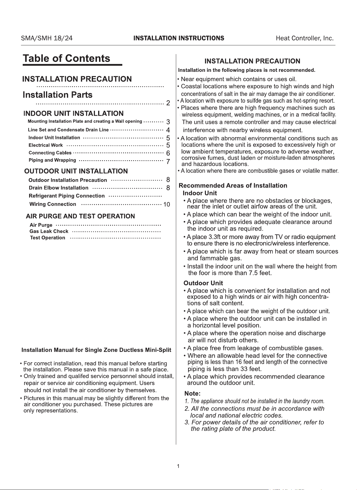
Heat Controller, Inc. INSTALLATION INSTRUCTIONS SMA/SMH 18/24
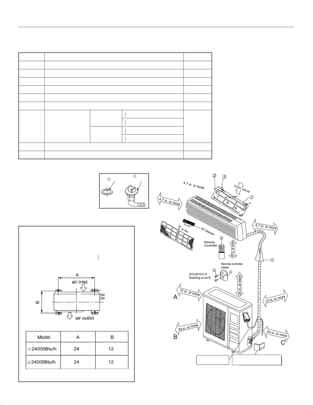
Installation Parts
Please install the accessories attached with unit correctly according to this installation manual.
Part No. Name of Part Quantity
1 Installation Plate 1
2 Anchor 8
3 Mounting Screw A (ST3.9x25-C-H) 8
4 Remote Controller 1
5 Remote Controller Holder 1
6 Mounting Screw B (ST2.9x10-C-H) 2
o 1/4" (<24,000 Btu/h)
Liquid side
o 3/8" (≥24,000Btu/h)
7 Refrigerant Pipe
o 1/2" (<24,000 Btu/h)
Gas Side
o 5/8" (≥24,000 Btu/h)
8 Seal* 1
9 Drain Elbow* 1
* See outdoor installation instructions
**Cautions on remote
controller installation
• Keep the remote controller at
least 3 feet from the nearest
TV set or stereo equipment
to advoid possible electronic
interference.
• Do not leave the remote
controller in a place exposed
to direct sunlight or close to
a heating source, such as a
stove.
• Ensure that the positive and
negative poles are correct
when inserting batteries into
the remote controller.
8
Seal
Anchoring the Outdoor Unit
• The outdoor unit should not be exposed
to strong winds
• Anchor the outdoor unit with o5/16"
anchor bolts
9
Drain
Elbow
U Bend example
Remove the water receiver rst
before connecting the piipes
NOTICE: There should be at least two of the air ow inlets/
oulets labeled “A”, “B”, “C” above free from blockage.
2
Page 4
SMA/SMH 18/24 INSTALLATION INSTRUCTIONS Heat Controller, Inc.
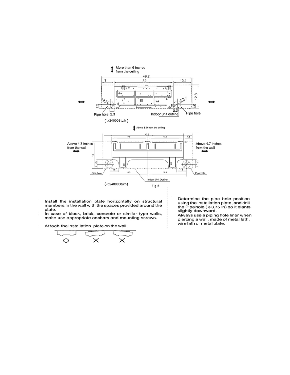
INDOOR UNIT INSTALLATION
1. Mounting Installation Plate and creating a Wall opening
Installation Plate and its measurements (inches):
Clearance:
Clearance:
5 inches or more
Clearance: Clearance:
1. Attach the installation plate
A.
B.
C.
Clearance:
Clearance:
5 inches or more
2. Creating a wall opening
A.
B.
3
Page 5
Heat Controller, Inc. INSTALLATION INSTRUCTIONS SMA/SMH 18/24
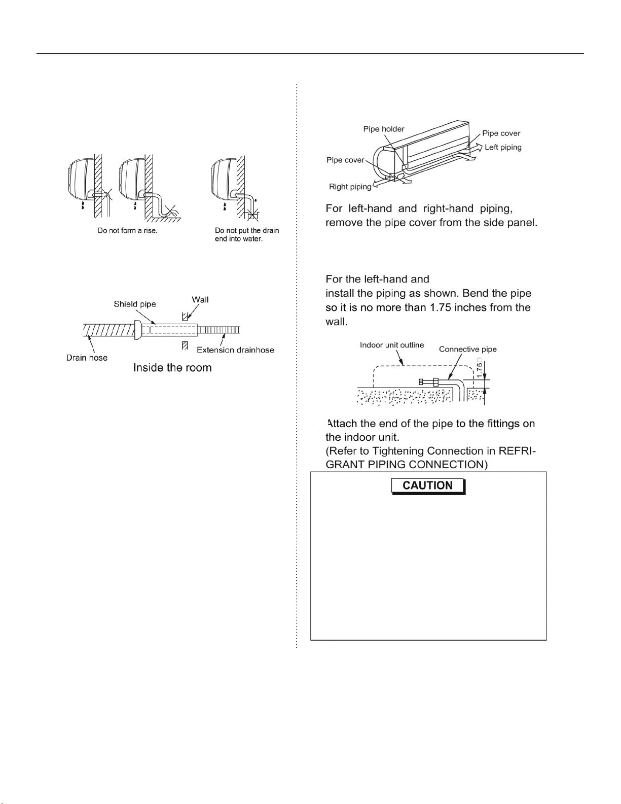
2. Line Set and Condensate Drain Line
1. Condenstate Drain
A. Run the drain hose sloping downward. DO
NOT install the drain hose as illustrated below.
B. When extending the drain hose, insulate
appropriately.
2. Line Set
A.
B.
Left rear piping
Right rear piping
left-rear-hand piping,
C.
• Connect the indoor unit rst, then the outdoor
unit. Bend and arrange the piping carefully.
• Do not allow the piping to loosen from the
indoor unit during installation.
• Be sure not to let the drain hose slack.
• Insulate both pipes.
• Do not allow the power cable and control cable
to be crossed.
4
Page 6

Page 7

Heat Controller, Inc. INSTALLATION INSTRUCTIONS SMA/SMH 18/24
5. Connecting Cables
A. Lift the panel, loosen the screw, then open the Electric Box Cover.
B.
C. Wrap cables not connected to terminals with electrical tape so that
they will not touch any electrical components.
6
Page 8

SMA/SMH 18/24 INSTALLATION INSTRUCTIONS Heat Controller, Inc.
6. Piping and Wrapping
A. For the left-hand and right-hand piping, remove the rear
plate bushing from the left side of the rear plate.
B. Wind the line set, drain hose and wiring with tape se-
curely and evenly. Consult local and national electrical
codes for proper routing and placement of electrical
wiring.
C. When installing the indoor unit lower than the outdoor
unit, make a “u-bend” trap to prevent rain water from
running along the connecting pipe to the inside of the
building/room where the indoor unit is located.
wrap
line set.
Before wrapping electrical wiring with line set, consult local and
national codes for proper installation of line voltage wiring.
7
Page 9

Heat Controller, Inc. INSTALLATION INSTRUCTIONS SMA/SMH 18/24
OUTDOOR UNIT INSTALLATION
1. Outdoor Installation Precaution
• Install the outdoor unit on a rigid base to prevent noise and vibration.
• Locate the air outlet direction where the discharged air is not blocked.
Ensure there are no obstacles blocking the unit’s air ow.
• If the installation location is exposed to strong winds, place the unit length
wise along a wall or use shield plates to protect against high winds.
• If suspending the unit, the installation wall should be solid brick, concrete or of similar construction. If
not, reinforce the supporting wall. The connections between the bracket and wall and the bracket and
the air conditioner must be rm, stable and reliable. Consult all local and national building codes.
• If suspending the unit, follow the instructions provided by the bracket manufacturer.
2. Drain Elbow Installation
Fit the seal into the drain elbow,
then insert the drain elbow into the
outdoor unit’s base pan hole, rotate
90° to securely assemble them. To
discharge excessive condensate
from the outdoor unit when in heating
mode, connect the drain elbow to a
8
9
drain hose (locally purchased).
8
Page 10

SMA/SMH 18/24 INSTALLATION INSTRUCTIONS Heat Controller, Inc.
3. Refrigerant Piping Connection
1. Flaring
A.
B.
.04
2. Tightening Connection
A.
B.
Hand tighten the are nut and then tighten it
with a spanner and torque wrench as shown.
Excessive torque can break the are nut. Ensure
the proper torque is adhered to in the chart below.
9
Page 11

Heat Controller, Inc. INSTALLATION INSTRUCTIONS SMA/SMH 18/24
4. Wiring Connection
A.
B.
C.
D.
E.
F.
Use a dedicated circuit. Use HACR break sized per
unit’s rating plate. Size wires according to minimum
circuit ampacity shown on the unit’s rating plate.
• Be sure to comply with local and national electrical codes while running the wire from the indoor
unit to the outdoor unit.
• Install disconnects fro the outdoor and indoor
units as required by national and local electrical
codes.
• Every wire must be connected rmly. Loose wiring may cause the terminal to overheat or result
in unit malfunction. A re hazard may also exsist.
NOTE: To prevent wire from loosening, secure
wires and/or cords under cord clamp.
10
Page 12
SMA/SMH 18/24 INSTALLATION INSTRUCTIONS Heat Controller, Inc.
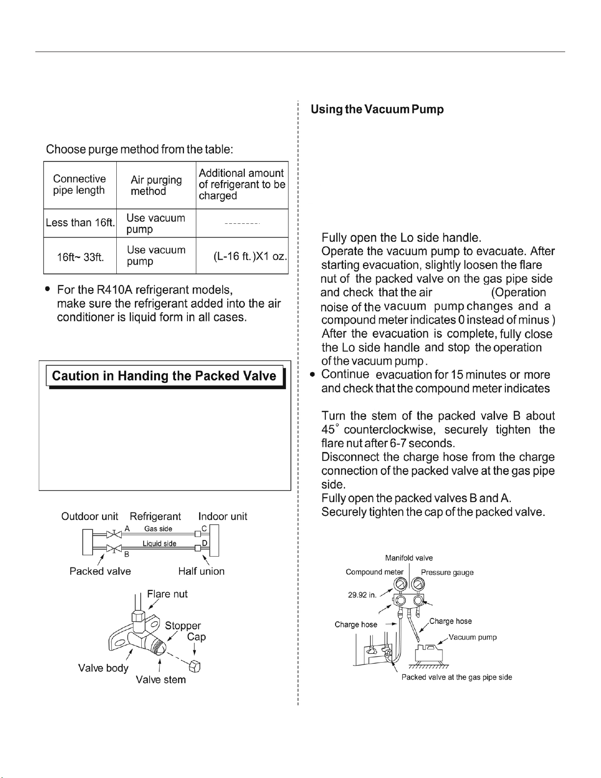
AIR PURGE AND TEST OPERATION
1. Air Purge
A.
Completely tighten the are nuts A, B, C, D.
Connect the manifold valve charge hose to the
charge port of the packed valve on the gas pipe
side.
B.
Connect the charge hose to the vacuum
pump.
C.
D.
where L=Length
is entering.
• Open the valve stem until it hits against the stop.
Do not try to open it further.
• Securely tighten the valve stem cap with a
spanner or wrench.
• Torque the valve properly:
Gas pipe side (0.38"): 23.5 N-cm (300 kgf-cm)
Liquid pipe side (0.25"): 12.56 N-cm (160 kgf-cm)
E.
-29.92 inHg.
F.
G.
H.
-
Lo Handle
Hi Handle
11
Page 13
Heat Controller, Inc. INSTALLATION INSTRUCTIONS SMA/SMH 18/24
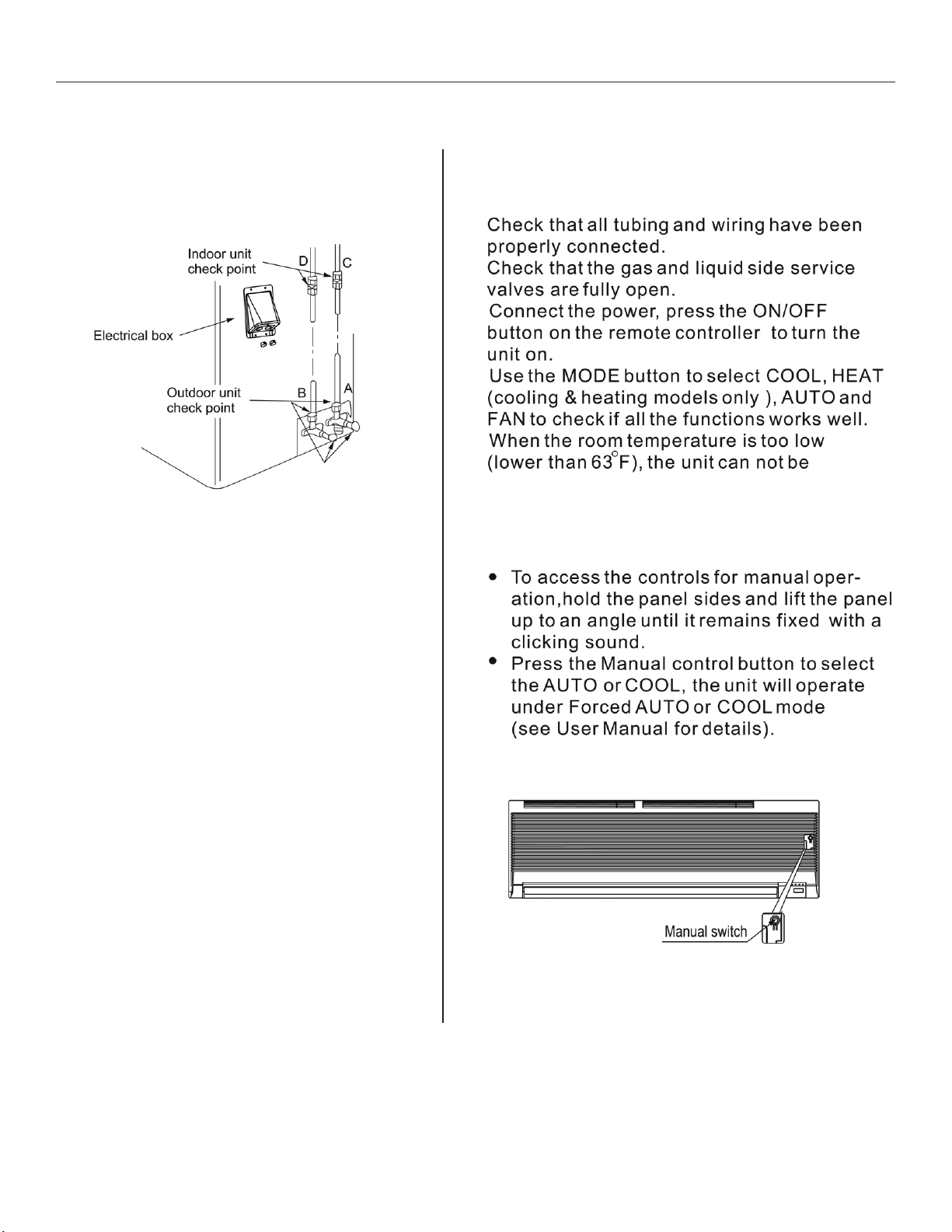
2. Gas Leak Check 3. Test Operation
Make sure connections do not leak
with leak detector or soapy water.
A. Lo packed valve
B. Hi packed valve
C. End of indoor unit connection
D. End of indoor unit connection
soapy water.
Test the unit’s operation after completing gas leak
check at all are nut connections and complete
an electrical safety check.
A.
B.
C.
D.
E.
controlled by the remote controller to run in
cooling mode. Manual operation must be used
when the remote controller is disabled or when
maintenance is necessary.
12
The test operation should last about 30 minutes.F.
Page 14

 Loading...