

Page 1

INSTALLATION
INSTRUCTIONS
SMALL DUCT HIGH VELOCITY:
Duct Layout
Heat Controller, Inc. • 1900 Wellworth Ave. • Jackson, MI 49203 • (517)787-2100 • www.heatcontroller.com
Page 2
Bulletin 100-135 / August 2010
Installation Guide
This instruction is a summary of the basic rules and applies to most applications.
Duct Layout
Outlets
7 two inch outlets Per Ton / 5 two and a half inch outlets Per Ton (3.5 kW). For refrigerant cooling applications the
airflow must be between 200 and 250 CFM per nominal ton [27 to 33 L/s per nominal cooling kW]. For hot water or chilled
water systems, refer to performance charts for determine the required airflow. The allowable airflow range per 2 inch outlet
is 20 to 40 CFM [9.4 and 19 L/s] and 25 to 55 CFM [11.8 and 23.75 L/s], where the typical ou tlet will deliv er 35 CFM [17
L/s] if the plenum static pressure is 1.5 inches [0.37 kPa] and the branch duct length is 10-foot (3 meter) without any
balancing orifices. Therefore, the average project will require about 7 2 inch outlets or 5 two and a half inch outlets per
nominal ton although more will be needed if the branch ducts are longer, balancing orifices are used, the plenum static
pressure is less than 1.5 inches of water [0.37 kPa], or it is desirable to make the system as quiet as possible. For example,
two runs with 50% balancing orifices are equal to one branch run without any orifices.
10% Rule. For supply ducts longer than 10 feet (3 meter), the air is reduced in that run by 10% for every 5 feet over 10
(every 1.5 meter over 3 meters). For example, a 30 foot [9 meter] run is 60% of an outlet that is 10 foot [3 m] yielding a
reduction of 40% (30-10=20, 20
Consider Traffic Pattern. Place outlets out of traffic pattern. A corner, 5-inch [127 mm] from each wall, is a good location,
or along walls, or in soffits blowing horizontally. Consider floor outlets (with screens) for units located in basement. Slotted
outlets can be used for high wall locations or in ceilings where there is insufficient room for bending tubing.
Allow for Aspiration. Locate outlets so the air stream does not impinge on any objects or people — at least 3 feet [1 m]
away. Use outlet deflectors and outlet balancing orifices sparingly as they disrupt the aspiration.
Minimize Length, Minimize Restriction. Keep the supply duct length as close to 10 feet [3 m] as possible and never less
than 6 feet [1.8 meters]. Use the fewest number of bends as possible. Maximize the radius of any bends making sure the
bend in the sound attenuator tubing near the outlet is at least 6-inch [152 mm].
Plenum
Maximize Length, Minimize Restriction. Run main trunk (plenum) as long as possible; it is better to lengthen the plenum
if you can shorten even two outlet runs. Use full flow tees with turning vanes (when applicable) and full flow elbows. The
maximum total plenum length is 150 ft [45 m]; consider the first tee equal to 30 ft [9 m] and elbows equal to 15 ft [4.6 m].
60/40 Rule. When using a tee split the flow as close to 50/50 as possible — no more than 60/40. Always use a turning vane.
70/30 Rule. Turn the tee 90° to make a side branch with no more than 30 percent of the air. Do not use a turning vane
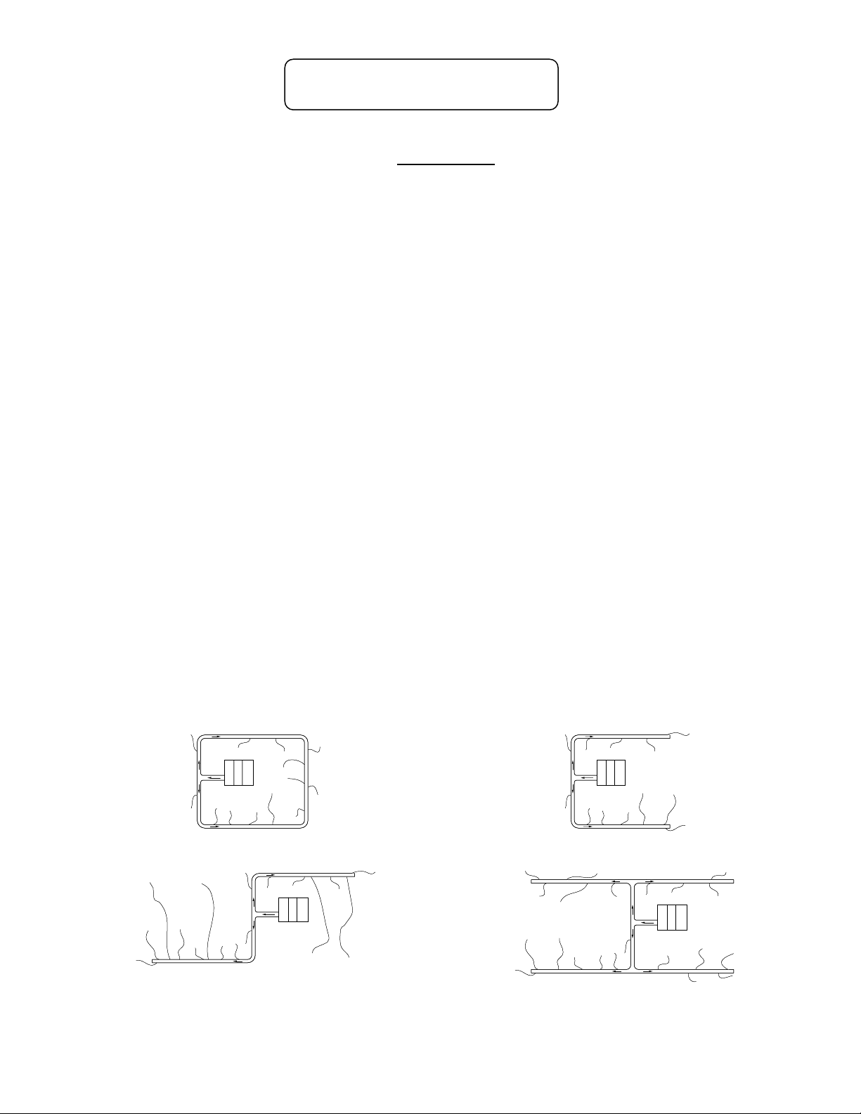
Horseshoe Patterns. (Best Method). Use a tee at least 24 inches [610 mm] off unit. For the 4860 unit, use 10-inch [254
mm] metal up to and including tee; then use 9-inch [229 mm] both directions. For the 3642 unit, use 9-inch [229 mm]
insulated metal up to and including tee; then use 7-inch [178 mm] both directions. If possible, close the horseshoe into a
perimeter loop.
5=4, 410=40%).
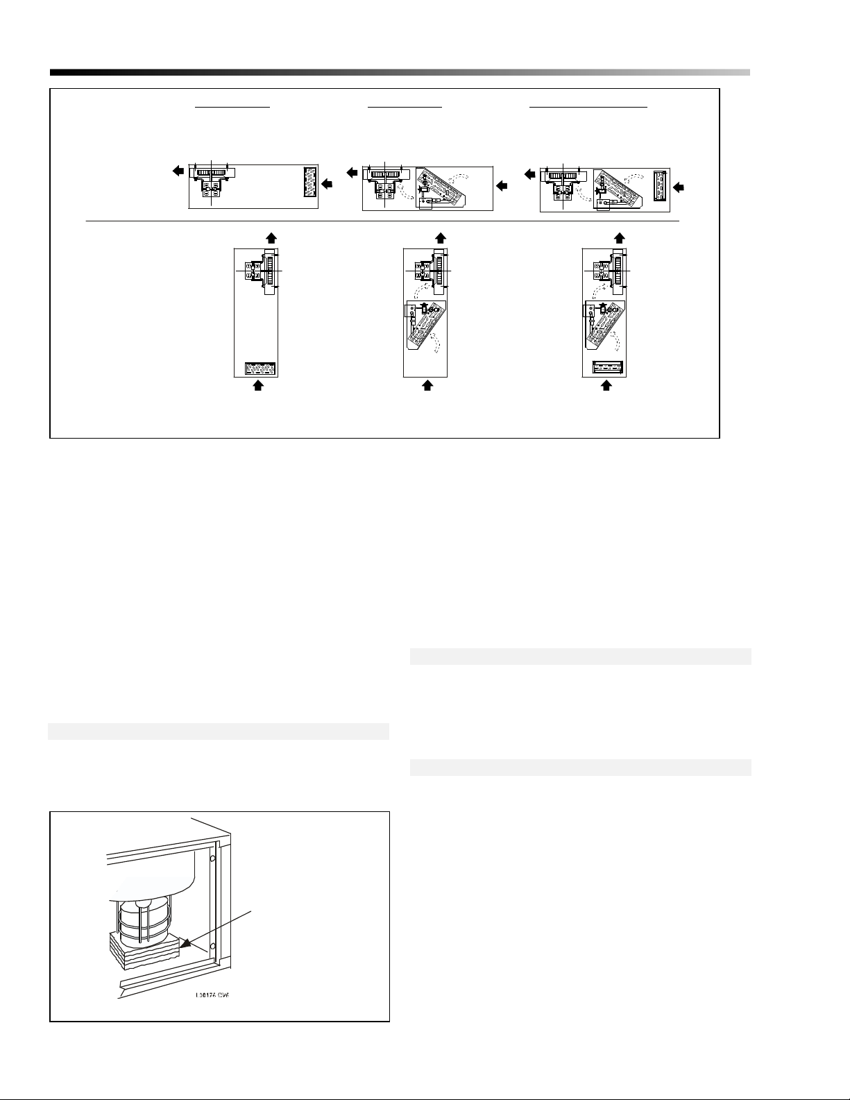
PERIMETER LOOP SYSTEM
DOGLEG SYSTEM
Note — Specifications, Ratings, and Dimensions are subject to change without notice. Copyright© 2010 Heat Controller, Inc.
IL00121.CVS
IL00123.CVS
HORSESHOE SYSTEM
'H' SYSTEM
IL00122.CVS
IL00125.CVS
Page 3
Bulletin 100-135 — Page 2
V
Plenum (cont.)
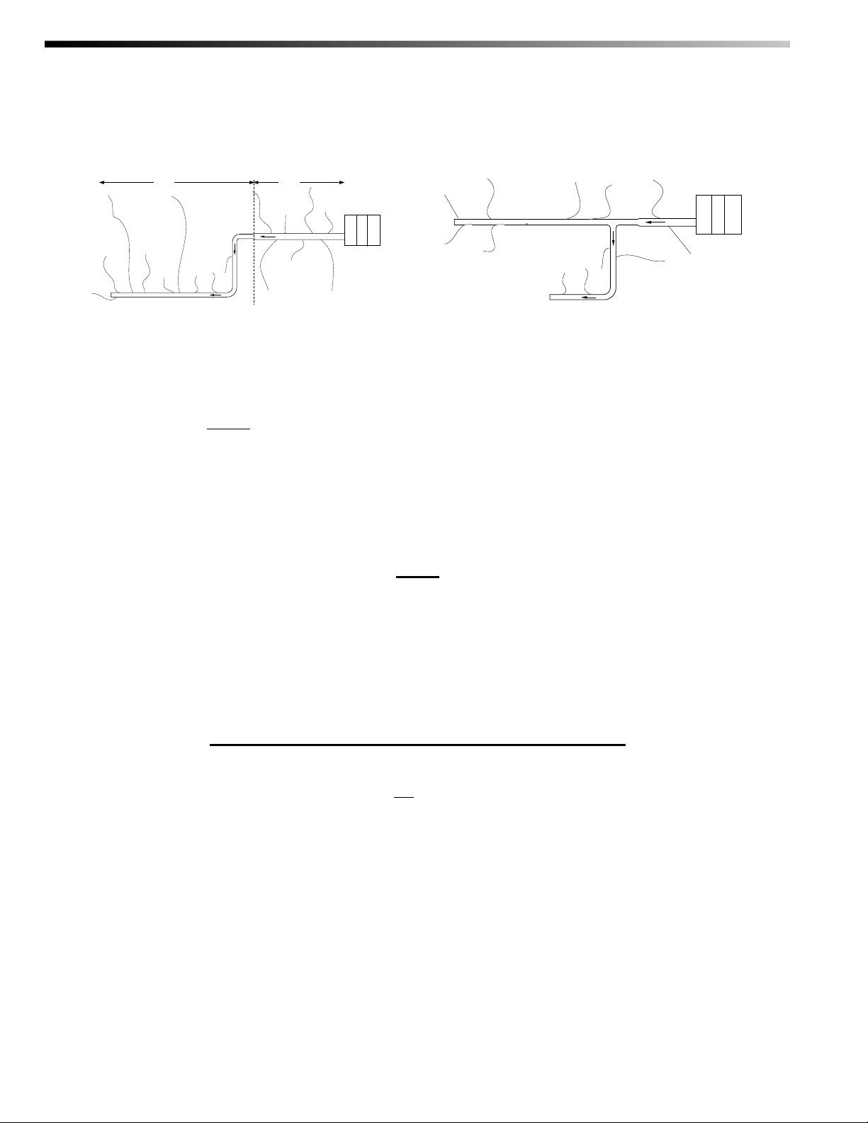
Shotgun Pattern. For the SDAH48 and SDAH60 series units, use 10-inch [254 mm] insulated metal duct for the first 30
percent; then reduce to 9-inch [229 mm] if desired. For the SDAH36 unit, use 9-inch [229 mm] insulated metal duct for the
first 40 percent; then reduce to 7-inch [178 mm] if desired. For the SDAH24 unit, 7-inch [178 mm] may be run the entire
length.
40 %60 %
9-INCHDIA.
7-INCHDIA.
24-inch (610 mm) Rule. Use at least 24-inch [610 mm] of straight plenum before any fitting, such as an elbow, tee, or
IL00124.CN
30% MAX.
IL00126.CNV
takeoff. Electric duct heaters require 48 inches [1.2 m]. Avoid elbows directly off units.
Space Takeoffs Evenly. Maintain distance between takeoffs as evenly as possible. Space the takeoffs at least 6-inch [152
mm] apart and 12-inch [305 mm] from end cap.
Sound
Sound Attenuators. Always use at least 3 feet [1 m] of the Heat Controller supplied sound attenuator supply tubing (SD-
26C or SD-226C) at the end of each run. For runs up to 12 feet [3658 mm], you may use the sound attenuator for the entire
run. For greater lengths, use the aluminum core supply tubing (SD-25 or SD-225) with a 3 foot [1 m] sound attenuator at the
end.
Return Air Duct Attenuation. Use the Heat Controller Return Air Duct (SD-04) sheet metal with acoustical duct liner.
Never use flex duct with a solid plastic liner in place of SD-04.
Isolation. Isolate the air handler with foam rubber strips under the unit. Either hang the unit from the structure using angle
iron framework under unit (do not hang directly with hooks in the cabinet) or set on a platform.
Piping
Secondary Drain Pan. Always use a secondary drain pan wherever overflow of condensate can cause water damage. Do
not trap secondary drain line or connect to primary drainpipe. Place secondary drain line exit so that it is apparent when
being used. For example, pipe the drain line so it drips on an outdoor windowsill and causes splashing to be noticed.
Primary Drain. Always trap primary drain line and run drain line per local plumbing codes.
Refrigerant Lines. Follow outdoor section manufacturer's instructions for running refrigerant lines. Size and trap per their
instructions.
Check Total System Airflow. Check the airflow at each outlet with a Turbometer centered over the outlet. Add up the cfm
for all outlets – it should not differ by +/- 5% from the design airflow.
STARTUP — DO THIS BEFORE BOXING-IN THE DUCT WORK.
Check Static Pressure (optional). Measure the external static pressure in plenum 2 feet [610 mm] from unit and before any
fitting. Set as close as possible to 1.5 inches of water [0.37 kPa] or less, but no less than 1.0 IWC [0.25 kPa] or greater than
1.8 IWC [0.48 kPa], by providing a dequate number of full
Check Amperage. Measure the amperage and voltage of the motor. Verify that it matches within +/- 5% of the values for
the desired (design) cfm in the installation manual or the motor amperage table shipped with each air handler. Also, use a
Turbometer
®
to measure airflow from each outlet. If the total airflow measured by the Turbometer at the outlets is
outlets and minimum plenum fittings (full flow).
significantly less than airflow determined by motor amperage, check for system air leaks.
Check for Full Flow. Inspect each outlet for full flow (except where balancing orifices or used or for long branch ducts).
Investigate for blockage or kinks if flow is insu ffi ci ent.
Check Refrigerant Charge. Charge unit per outdoor manufacturer's instructions and Unico's Installation instructions. For
best results use the subcooling method during the cooling cycle. Heat pu mps should be checked in both heating and cooling.
TurboMeter® is a registered trademark of Davis Instruments
Page 4
INSTALLATION
INSTRUCTIONS
SMALL DUCT HIGH VELOCITY:
SDAH18 Air Handler
Heat Controller, Inc. • 1900 Wellworth Ave. • Jackson, MI 49203 • (517)787-2100 • www.heatcontroller.com
Page 5
Bulletin 100-150 / August 2010
INSTALLATION MANUAL
SHAH18 Air Handler
NOTICE TO INSTALLER AND EQUIPMENT OWNER: RETAIN THIS MANUAL AT THE JOB
Il0015 9.CV5
General
The information on the following pages is to help the installer save
time, provide the best possible installation and insure continuous
trouble-free operation.
Scope
These instructions apply to the Heat Controller SDAH18 fan-coil
unit. Installation instructions for the air distribution system are
covered in other bulletins. Before beginning any installation, a
detailed system layout must be done in accordance with Bulletin
100-255 System Sizing and Layout bulletin.
SUFFICIENT BUILDING INSULATION IS
ESSENTIAL FOR THE MOST ECONOMICAL
OPERATION
General Precautions and Safety Tips
Do not attempt to install or startup unit without first reading and
understanding the appropriate sections in this manual. Before
operating, be sure the unit is properly grounded.
Installation should be in accordance with all local codes and
regulations and with the National Fire Protection Association and
Underwriters Laboratories applicable standards and regulations. In
case of conflict, local codes take precedence.
All electrical wiring should be in accordance with the latest edition
of the National Electrical Code and all local codes and regulations.
Condensate piping should be installed in accordance with
governing code.
Always install a secondary drain pan when an overflow of
condensate could cause damage.
TABLE OF CONTENTS
INTRODUCTION........................................................ 1
UNPACKING .............................................................. 2
LOCATION ................................................................. 2
SECONDARY DRAIN PAN ........................................ 3
MOUNTING................................................................ 4
Horizontal Platform .............................................. 4
Horizontal Suspended ......................................... 4
Ceiling.................................................................. 4
Vertical................................................................. 5
DUCT CONNECTION ................................................ 5
Supply Plenum..................................................... 5
Return Duct.......................................................... 5
PIPING ....................................................................... 6
Condensate Lines................................................ 6
Refrigerant Lines.................................................. 7
Expansion Valve ................................................... 7
Water Connections .............................................. 7
CHARGING AND STARTUP...................................... 8
Sequence of Operation........................................ 8
Fan Speed ............................................................ 8
Checking Airflow ................................................... 9
Charging a Cooling System .................................. 9
Low Ambient Control Kit ..................................... 11
Charging a Heat Pump System .......................... 11
Mild Weather Kit ................................................. 11
APPENDIX A - Hot Water Coil Capacities ................ 12
APPENDIX B – Chilled Water Coil Capacities .......... 12
APPENDIX C - Specifications ................................... 13
Part Numbers
This manual does not always include the latest revision
letter when referring to SD part numbers. Refer to the latest
Price List and Spec Sheets for the current revision letter.
INTRODUCTION
The Heat Controller Small Duct High Velocity air handler is
a complete indoor comfort system that includes an indoor
fan coil unit and small duct system. The fan coil unit and
duct system were designed to operate together to provide
the proper airflow in every installation. The conditioned air
is supplied through a series of two-inch or 2 ½ inch
diameter ducts as a stream of air that entrains and mixes
with the room air. This process of aspiration produces a
more even temperature distribution throughout the occupied
space.
Page 6
Bulletin 100-150 — Page 2
Heating Only
Blower Cabinet
+ Hot Water Coil)
Cooling Only
Blower Cabinet
+ Cooling Coil
Horiz ontal
Flow
Vert ical
UpFlow
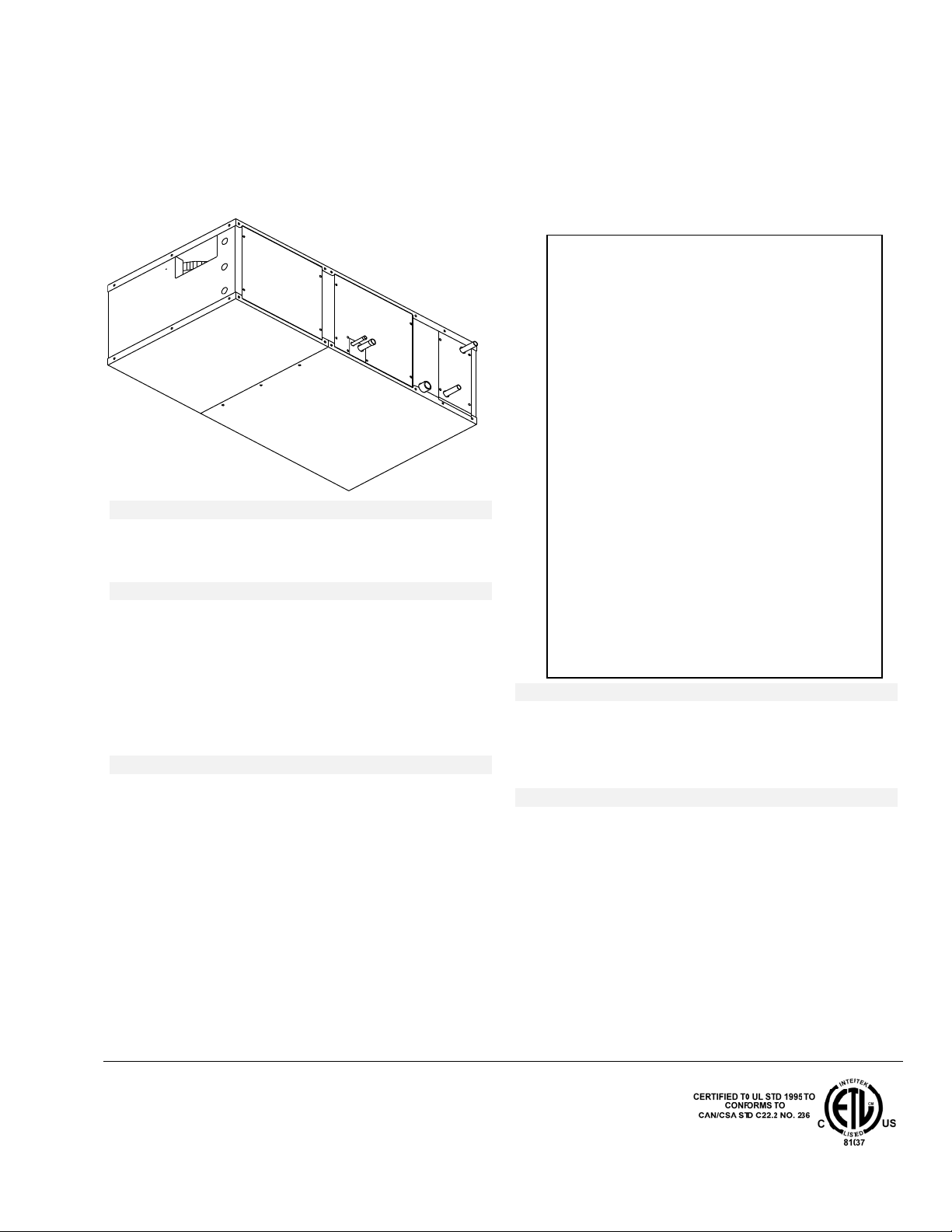
Figure 1. Unit Arrangement
The Heat Controller SDAH18 fan-coil unit is a single
packaged unit. The cooling and heating coils are contained
within the same cabinet. The unit can be mounted in a
vertical up-flow or horizontal-flow configuration. The coils
can be combined as a heating-only, cooling-only, or heating
and cooling fan coil unit. See Fig. 1.
Heating and Cooling
Blower Cabinet
+ Hot water Coil
+ Cooling Coil
OUT
IN
IL00148.CV5
Open the carton to remove the unit. Inspect unit for visible
signs of concealed damage and notify carrier of any such
damage. All materials are sold FOB Factory and it is the
responsibility of the consignee to file any claims with the
delivering carrier for materials received in a damaged
condition.
The unit is available in one size; 38-in L x 20-in W x 12-in
H (965-mm x 508 mm x 305-mm). The heating only system
includes the blower/motor and a hot water coil. The cooling
only system includes the blower/motor and a cooling coil.
For the heating and cooling system both coils are provided.
The cooling coil may be a heat pump coil or a chilled water
coil. The electrical panel is located inside of the cabinet.
UNPACKING
All units are inspected prior to shipping and are carefully
packaged in individual cartons. Inspect all cartons prior to
unpacking. Notify carrier of any damage.
CARDBOA RD
SUP PORTS
Figure 2. Location of Motor Shipping Supports
Open the blow er access panel to remov e the
motor shipping support. See Fig. 2. . The
expansion valve is shipped loose and is located in
the coil compartment near the connections.
MOUNTING
The unit ships installation ready for either horizontal or
vertical airflow applications (see Fig. 1) and may be
mounted to a structure using the optional mounting rails
(SD- 95).
LOCATION
Locate the air handler to minimize the number of plenum
elbows and fittings while keeping the supply duct runs as
short as possible. (See Bulletin 100-250, Component
Layout). The fully insulated cabinet allows installation with
zero clearance to the top, bottom, or sides of the unit.
However, clearance must be provided for servicing which is
dependent on how the unit is installed. Servicing of the
blower/motor assembly and coils can be performed in three
different ways:
1. The complete top panel, which is attached to
blower/motor assembly, can be removed. To do this,
the motor leads must be disconnected in the control
compartment.
Page 7
1 (25) Minimum
Supply plenum
1(25)Minimum
Supply Plenum
Supply plenum
All dimensions in inches (mm).
Side View
Air Flow
Air Flow
Air Flow
18 (457) bottom
clearance for
Top View
24(610) side
clearance for service
Suspended Installation
Side View
service
12
Return Duct
"
38
"
Return Duct
20
"
38
"
12
Return Duct
"
38
"
IL00149.CV5
Figure 3. Minimum Clearances
2. For side access remove the control panel, cooling coil
panel, or heating panel which are located on the same
side as the refrigerant, drain, and water connections.
3. Where the unit is suspended or mounted on the wall
using the mounting rails, the panel below the
blower/motor assembly can be removed for servicing.
In this case access to the coils must be from the side
access panels. See Fig. 3.
Bulletin 100-150 — Page 3
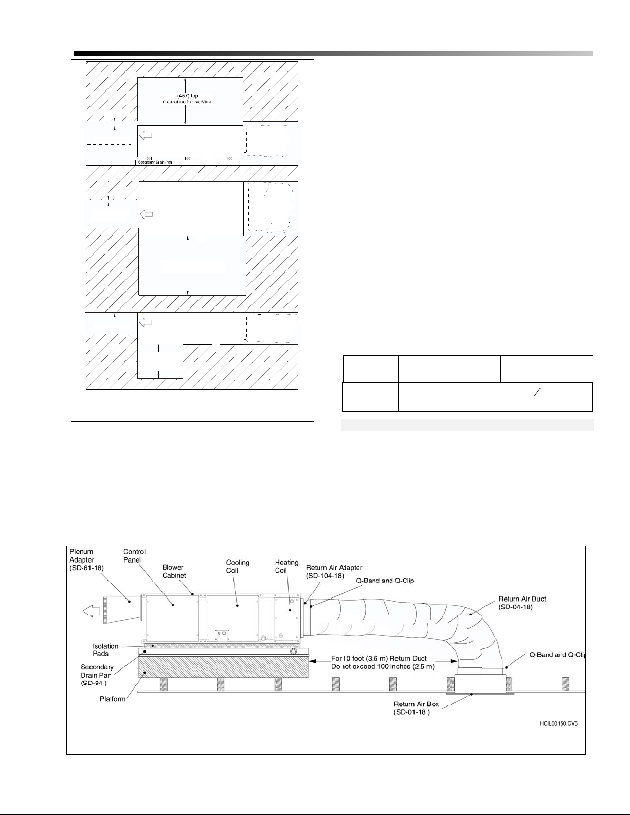
Position the return air box and filter near the unit allowing
at least one 90° bend in the return duct for proper acoustical
performance. Fig. 4 shows a typical horizontal attic
installation
The standard return duct is 10 feet (3 m) in length so it may
have to be cut to avoid bunching if the distance to the unit is
significantly less than 100 inches. If needed, up to two
return ducts can be coupled to make a 20-ft (6-m) duct. The
minimum length should be 6 feet (2 m). When given a
choice, maximize the distance and make at least one 90°
bend for the best sound attenuation.
Each unit is designed to fit into a small space where a
conventional unit could not be used. The 12-in. height
allows the unit to fit through joists or studs spaced at least
16-inches (406 mm) on center. If no access is provided, an
opening must be cut. It is suggested to use the opening
required for the return air box, especially in an attic
installation. The opening size for the return air box is listed
in Table 1. If the joists or studs are significantly less than 1 6
inches (406 mm) center-to-center or running the wrong
direction it would be necessary to cut and header the joists.
Table 1. Return Air Box Opening
Model Return Air Box Part No.
SDAH18 SD-01-18
Size of opening
inches (mm)
3
20 ½
14
8
(365 521)
Secondary Drain Pan
Where an overflow of condensate could cause water
damage, a secondary drain pan MUST BE INSTALLED .
Place the drain pan on the mounting base, platform or angle
iron support frame. Be sure to allow enough room for the
drain line and connection (refer to Table 2). The unit should
be placed over the secondary drain pan. Use rubber pads for
isolation to raise the unit high enough in the secondary
drain pan for the drain line to clear the side.
Figure 4. Typical Horizontal Attic Installation, SDAH18
Page 8
Bulletin 100-150 — Page 4
Table 2. Secondary Drain Pan
Unit Size Part No.
SDAH18 SD- 94
† NOTE — The drain fitting extends 7/8 inch (22 mm) beyond this dimension.
Dimensions
inches (mm)
40 x 22=
(1016 x 559)
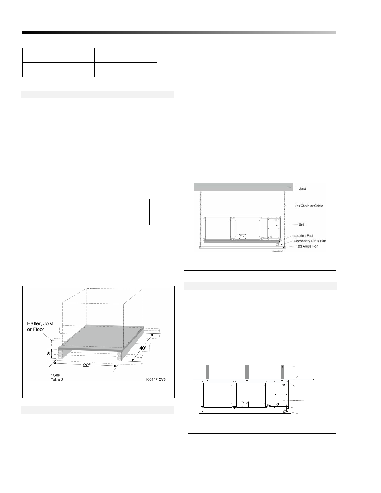
Horizontal Platform Mounting
Mount the unit horizontally when vertical height is limited
such as in an attic or crawl space. It is easiest to mount the
unit on a platform but care must be taken to assure proper
drain line pitch.
The platform height must allow for proper pitch of the
condensate drain lines — at least ¼ inch drop per linear foot
(20 mm per meter). The platform can be built from a sheet
of ½ inch (13 mm) plywood and stud frame. Table 3 lists
the maximum horizontal drain line run for various framing
materials and still provide adequate drainage.
Table 3. Horizontal Dist ance of Drain Piping for
Different Framing Materials
Frame Lumber:
Max. Horizontal Run,
ft. (m)
2 x 4 2 x 6 2 x 8 2 x 10
18 (5) 26 (8) 34 (10) 42 (13)
CAUTION
DO NOT HANG UNIT FROM TOP OF
CABINET IF NOT USING MOUNTING RAILS
TO AVOID DAMAGING THE EQUIPMENT.
Use either four (4) chains or steel cables with 80 lbs. (36
kg) test strength to hang the unit. Use eyebolts and ‘J”
hooks as applicable to attach the chains or cables to the unit
and the ceiling.
Place the unit inside of the secondary drain pan as you
would for platform support with the angle iron supports
lengthwise under the secondary drain pan. Level the unit by
adjusting the length of the chains or cables.
If using the alternative method, hang the secondary drain
pan from the unit using self-tapping screws and metal straps
or wires. Adjust the straps or wires to pitch the secondary
drain pan toward the drain connection.
The platform size should be a minimum of 22 x 40 inches
(559 x 1016 mm).
Place secondary drain pan on platform and unit on top of
isolation pads inside of secondary drain pan. Be sure that
the unit is raised high enough in the drain pan to allow for
primary drain line condensate connection.
Figure 5. Typical Platform Installation
Horizontal Suspended Mounting
The unit can also be suspended from the ceiling or rafters.
The preferred method is to support the unit and the
secondary drain pan from underneath with angle iron
supports (see Fig. 6). As an alternative, the unit can be hung
with the mounting rails.
Figure 6. Typical Horizontal Suspension Mounting
Ceiling Mounting
If desired, the unit can be mounted flush to the ceiling (see
Fig. 7) using the optional mounting rails (SD–95). Remove
top screws from both sides of the unit. Align holes on
mounting rails with the holes on the unit. Fasten mounting
rails to the unit with the screws that were removed earlier.
Attach unit to a structural member. Suspend secondary
drain pain from the unit with metal straps or wires.
Joist
Ceiling
Mounting Rails
Unit
Metal Straps o r Wires
Figure 7. Typical Ceiling Mounting
IL00164.CV 5
Seconda ry Drain Pa
Page 9
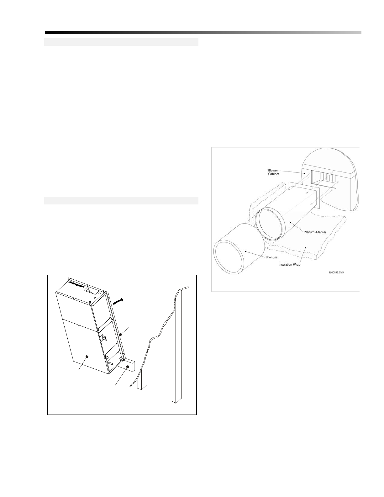
Vertical Rail Mounting
The unit can only be mounted in the vertical up-flow
configuration. The vertical rail mounting method is shown
in Figure 9. Mark hole pattern on wall and install stud
screws or lag screws (see Fig. 8).
To install the unit vertically, such as in a closet, basement,
or utility room, attach the mounting rails (SD-95) to the top
of the unit as explained previously. Screw or nail a
temporary board to the wall at the bottom of the location
where the unit will be mounted. The unit will rest on this
board during mounting. If the wall covering is not adequate
enough to hold the weight of the unit, use lag screws to
attach the rails to the structure. Use six (6) lag screws a
minimum of 3 inches (77 mm) long, which will be screwed
directly into a stud or structural member. If the wall
covering is sufficient, toggle screws may be used to mount
the unit. The board can be moved when the mounting of the
unit is completed.
DUCT CONNECTION
Supply Plenum
The standard supply plenum is a 7-inch (178-mm) diameter
duct, although this can be reduced to a 6-inch (152-mm)
diameter duct. The SDAH18 plenum adapter (SD-61-18)
provides a convenient connection to a 7 in (178-mm) duct.
Bulletin 100-150 — Page 5
on the unit. Mount the adapter with six (6) sheet metal
screws. See Figure 10.
Attach the plenum to the adapter by inserting it over the
collar. Use three (3) or four (4) equally spaced sheet metal
screws to secure the duct to the collar and then tape around
the seam with UL 181A aluminum tape. Then wrap the 1-in
fiberglass blanket duct insulation around the adapter and
seal with UL 181A aluminum tape.
The supply plenum also can be square or rectangular. The
inside dimensions of the duct must provide a minimum of
30 sq. in. (194 sq. cm.) of flow area, e.g. 5 x 6-in, 4 x 7 ½in (125 x 150, 100 x 190 mm).
The supply plenum can be a 7-inch ID rigid round
fiberglass or a sheet metal duct with a minimum thickness
of 26 gage. Refer to a separate bulletin for the installation of
the ductwork.
Wall
Mounting Rail
(SD-95)
Unit
Mounting Board
(temporary)
Il00162.Cv5
Figure 9. Typical vertical Rail Mounting
A 6-in plenum can be used so long as a 7-in duct is attached
to the unit and is then reduced at least 4-ft from the unit.
To attach the plenum adapter to the unit, align the holes on
the adapter with the holes located around the supply outlet
Figure 10. Plenum Adapter Installation
Return Duct
The Heat Controller return air system has a single return
that includes the return air box with filter, the acoustical
flex return duct, and the return air adapter (refer to Fig. 4).
Multiple returns or extra long returns are possible so long as
the maximum pressure loss is not exceeded. The return
system is designed for a maximum static pressure drop of
0.15 inches of water (37 Pa) including the filter. The return
duct should have at least one 90 degree bend between the
unit and filter box to reduce sound transmission directly
from the unit.
Although Heat Controller only supplies a single return
system, the return system can be redesigned for multiple
returns. The return duct system is a conventional duct
design not high velocity; therefore, the return system may
be different; provided, the static pressure does not exceed
0.15 inches of water column and there is some form of
sound attenuation. Generally, this means sizing the duct for
a pressure loss of 0.05 inches of water column at the
required airflow and sizing the filter for a pressure dr op of
0.10 inches of water column at the required airflow. Sound
Page 10
Bulletin 100-150 — Page 6
attenuation can be accomplished with fabricated duct board,
lined sheet metal, or acoustical flex (Part number SD-04-
18). For best attenuation, always have at least one 90
degree bend to eliminate direct line-of-site from the unit to
the return opening.
To install the return filter and grille, cut an opening for the
return box as specified in Table 1. If the joists or studs are
on 16 inch (410 mm) centers, there is no need to build a
frame to hold the return air box. Otherwise, it will be
necessary to construct a frame around the opening. Center
the return air box so the filter frame flange covers all the
gaps and make sure the flange is flush against the wall or
ceiling. Install the return air box against the frame using
nails or screws. Holes are provided in the return air box.
Use the four (4) ¼-inch (6.4 mm) holes. The other holes are
for mounting the filter grille.
Install filter frame into the return air box using four (4) nails
or screws. Insert filter and hold in place by rotating metal
clips. Close grille and secure with clips.
Connect the return air adapter to the unit u sing sheet metal
screws. Then attach the return duct to the adapter and to the
return air box using the supplied band. Tape the seams with
UL 181B duct tape.
PIPING
All piping must be in accordance with all local codes and
ordinances.
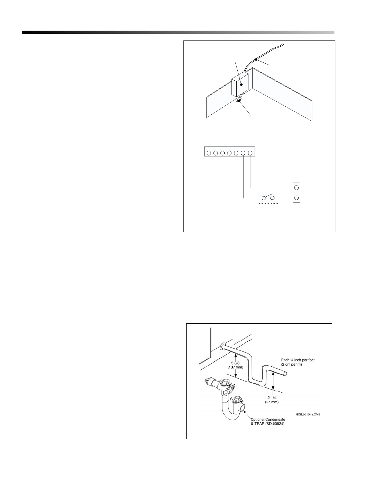
Condensate Lines
The primary drain pan condensate connection is a 1/2 inch
(13 mm) female pipe thread fitting and the secondary drain
pan connection is a 3/4 inch (19 mm) PVC socket fitting.
Elevate the unit so the condensate lines are pitched at least
¼ inch per lineal foot (20 mm per meter). Trap the
condensate line near the unit as shown in Figure 12. In
some cases it may be necessary to wrap the condensate line
near the unit with insulation to prevent water from
condensing on the outside of the pipe. In some climates or
locations it may be necessary to protect trap from freezing
in the winter.
Switch
Paper Fuse
Leads
Il00156.Cv5
Location of Paper Fuse
Indoor Terminal Block
1234 56 7
Condenser
R
Y
Switch
Il00157.CNV
Figure 13. Wiring Diagram for Paper Fuse
will dissolve and the switch will open causing th e outside
unit to shut down until it is serviced.
Also available is the Heat Controller Condensate U-Trap
which features a clear trap that is easy to visually inspect for
clogs. The U-Trap is designed for the Heat Controller
SDAH18 with a 2.5 inch (64mm) deep trap to handle the
higher static pressures. The U-Traps also feature easy to
remove clean-out caps and incorporate to tees to
accommodate any piping arrangement (Part No. SD-00924).
Do not trap the secondary drain line and do not terminate
line into the primary drain line. Run secondary drain line so
that any drainage will be immediately known without
causing damage to property. A typical location is to
terminate the secondary drain line above a windowsill so
that the drainage splashes on the window. This will serve as
an indicator that there is a problem with the primary drain.
An alternative method of notifying the homeowner about a
leakage problem is to use a paper fuse and micro switch.
See Fig. 13. Install a micro switch upside down on the side
of the secondary drain pan. Making sure that the switch is
open. Next, sandwich a paper fuse between the switch and
the bottom of the drain pan so that the switch is closed.
When water is present in the secondary drain pan, the fuse
Figure 12. Typical Condensate Trap
Page 11
Refrigerant Connections
CAUTION: WHEN BRAZING, PURGE WITH
NITROGEN GAS TO PREVENT THE
FORMATION OF OXIDES.
The refrigerant lines are copper sweat connections. The
liquid line is 3/8 inch (9.5 mm) OD and the suction line is
5/8 inch (16 mm) OD. Refer to the condensing unit
manufacturer’s instruction for proper line sizing information
based on distance from condenser.
Install a liquid line filter drier as close to the coil as possible
to protect the evaporator from foreign object debris. For
troubleshooting purposes, especially for attic installations or
when using long line sets, an optional moisture indicating
sight glass should also be installed between the filter-drier
and expansion valve near the indoor unit.
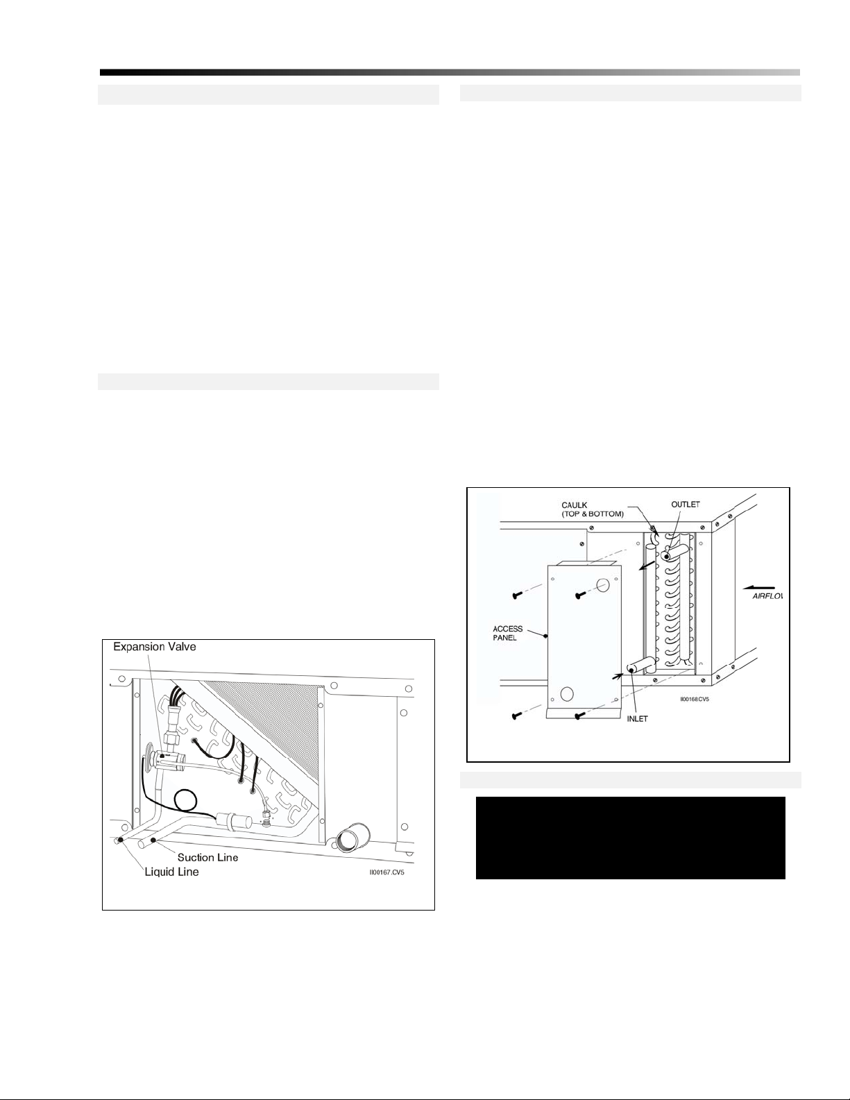
Expansion Valve
The expansion valve is shipped loose inside the unit in the
blower section. Install the valve inside the unit as shown in
Fig. 14. Use the following steps when installing:
1. Remove plastic caps to external equalizer line and
distributor inlet.
Bulletin 100-150 — Page 7
Water Connections
If you are installing the hot water coil, remove the side coil
access panel. Slide the coil into the cabinet if not already
installed at the factory and reinstall the door panel. After
removing plugs in the inlet and outlet holes, caulk around
connections to prevent leakage.
Pump and pipe sizing should be based on proper flow rate.
Refer to Appendix A for water coil capacities based on flow
rate.
All water connections are 5/8 inches OD (16 mm) sweat
connections. Sweat the water connections, then fill the
system. Install a vent valve at the highest point and a drain
valve at the lowest point of the water system (refer to Fig.
17). Fill and bleed the air from the system. If unit is in an
unconditioned space care must be taken to prevent the water
from freezing. Use a glycol-water antifreeze solution with a
freezing point below the coldest temperature expected.
As an alternate to an anti-freeze solution, the water can be
continuously circulated to prevent freezing. If the coil will
not be used for an extended period of time during cold
temperatures, drain the system then flush with a glycol
solution.
2. Connect valve to distributor and tighten flare nut.
3. Connect external equalizer line and tighten flare nut.
4. Connect to the outlet the 3/8” (9.5 mm) OD copper
refrigerant fitting. Make sure the flare nut is tight.
5. After all lines have been connected, pressure-check the
connections by charging the system with 150 psig of
dry nitrogen and check for leaks at all connections.
Figure 14. Expansion Valve Location
Locate the bulb at the 12 O’clock position on a horizontal
straight section of the 5/8” (16 mm) suction line (see Fig
15). Attach the bulb to the tubing with the two straps that
are provided. For satisfactory expansion valve control, good
thermal contact between the bulb and the suction line is
essential.
Figure 15. Hot Water Coil Connection
Wiring
WARNING!
DISCONNECT ELECTRICAL SUPPLY BEFORE WIRING UNIT TO PREVENT INJURY
OR DEATH FROM ELECTRICAL SHOCK.
All electrical wiring must comply with all local codes and
ordinances. Make electrical connection in accordance with
the wiring diagram shown in Fig. 18. Use a separate 1 ph 230/208V – 60/50 Hz power supply with a 15 amp fuse or
breaker and appropriate wire gauge per local code. Refer to
bulletin 100-180 for more information on wiring the System
Interface Board (SIB).
Page 12

Bulletin 100-150 — Page 8
Charging and Startup
Sequence of Operation
The sequence of operation depends greatly on the options
installed and type of control thermostat used. Most
thermostats have a fan AUTO-ON switch. When the fan
switch is set to ON, the “G” circuit is closed and the blo wer
relay is energized. The indoor blower starts after about a 20
second delay. The following paragraphs describe the
sequence of operation when the fan is set to AUTO. If the
fan switch is set to ON, the sequence is the same except the
“G” circuit is always closed and the indoor fan is always
operating.
Cooling Cycle (A/C or Heat Pump). When the thermostat calls for cooling, the “Y” and the “G” circuits are
closed, and a 24 V signal is sent to the compressor contactor
in the outdoor unit and fan relay in the indoor unit. After
about 20 seconds, the indoor blower starts. At the same
time, the compressor and outdoor fan also start. Depending
on the control circuitry in the outdoor unit, there may be a
time delay before the outdoor unit starts. If the system was
just turned off, the time delay could be as much as five
minutes. The cooling system is now operating.
For heat pump thermostats setting the switch to ‘cooling’
immediately closes the “O” circuit, which is used to
energize the reversing valve solenoid if required by the heat
pump. Otherwise, the “B” circuit, which closes when
switched in heating, is used to energize the reversing valve
solenoid. (Refer to the heat pump manufacturer’s
instructions to see which mode the solenoid needs to be
energized – whether in heating or cooling.)
When the thermostat is satisfied, the 24 V signals open and
the outdoor unit stops. The indoor blower continues to
operate for about 40 seconds, then stops. The system is now
off.
Heating Cy cle (Heat Pump). Setting the thermostat to
HEATING will automatically switch the reversing valve
solenoid. This setting closes the “B” circuit which sends a
24V signal to energize the solenoid if required by the heat
pump. Otherwise the “B” circuit is not used and the
solenoid is not energized during heating.
When the thermostat calls for heating, the “Y” and “G”
circuits are closed, sending a 24 V signal to the compressor
contactor in the outdoor unit and the fan relay in the indoor
unit. This starts the indoor blower and the outdoor
compressor and blower. There is a time delay of about 20
seconds for the indoor unit. The heating system is now
operating in stage one.
If the first stage does not satisfy the thermostat, the second
stage thermostat calls for more heat. This closes the “W2”
contacts and energizes the sequencer for electric heat. When
the second stage thermostat is satisfied, the “W2” circuit is
broken and the sequencer is de-energized. The electric
heating system is now off.
When the first stage thermostat is satisfied, the 24 V signals
open and the outdoor unit stops. The indoor blower
continues to operate for about 40 seconds, then stops. The
system is now off.
Heating Cy cle (Electric Heat). When the thermostat
calls for heating, the “W” and “G” circuits are closed. The
W circuit completes the 24V signal to the sequencer in the
electric duct heater, which cycles on the electric heating
elements. The G circuit completes the 24V signal to the fan
relay in the indoor unit, which starts the indoor blower after
a time delay of about 20 seconds. The heating system is
now operating.
When the thermostat is satisfied, the 24 V signals open and
the indoor blower stops after about 40 seconds. At the same
time the sequencer cuts the power to the electric elements.
The system is now off.
Note: Use a thermostat designed for electric
heat. A normal heating-cooling thermostat will
not close the “G” circuit on heating.
Heating Cy cle (Hy dronic Heat). When the thermostat
calls for heating, the “W” circuit is closed sending a 24 V
signal to the field installed heating relay. This relay closes
two circuits. One completes the boiler circuit, which either
opens a valve or starts a pump. The other completes the fan
relay circuit, energizing the blower motor relay and starting
the blower after a 20-second delay.
If an aquastat is utilized, the fan relay circuit will remain
open until the aquastat is satisfied.
When the thermostat is satisfied, the 24 V signal to the heat
relay opens and the pump or valve circuit opens which stops
the pump or closes a valve. The fan circuit opens and deenergizes the fan relay. After about 40-seconds the blower
stops.
Fan Speed
The SDAH18 comes standard with a 2-speed motor and
the Heat Controller SIB (System Interface Board). For
more information on this feature refer to Bulletin 100-
180.
Table 4. Motor Amperage versus Airflow
2-Speed
Motor
*Low speed for the optional 2- Speed motor produces half the
high speed airflow (1.0 amp @ 230V)
Airflow
CFM (l /s)
200 (94) 1.15 *
300 (142) 1.30 *
400 (189) 1.48 *
Check for the proper airflow by measuring the
amperage and compare to Table 4. For hot water
systems, refer to Appendix A for minimum airflow.
Amperage @ 230V
High Speed Low Speed
Page 13

Checking Airflow.
CAUTION. DO NOT OPERATE BLOWER
WITH FREE DISCHARGE OR LOW STATIC
PRESSURES (BELOW 1 INCH WC (250 Pa))
TO PREVENT MOTOR FROM OVERLOADING.
After the system is installed and before charging system,
check for proper airflow. Record the plenum static pressure
and the motor amperage and voltage. With this information,
the amount of airflow can be determined.
As a recommended further check on airflow, use a
velometer to measure the CFM from each outlet. The most
convenient instrument to use is a hand held vane type
velocity meter that fits directly over the outlet. The TurboMeter (Davis Instruments Catalog No. DS105I07) or
equivalent meter will give a direct LED readout on the
KNOTS (FPM x 100) setting, when multiplied by 2 gives
the CFM of the outlet within an accuracy of 10%.
By measuring and totaling the CFM of all outlets, the to tal
airflow of the system can be closely approximated and
provide a crosscheck for the airflow determined from the
motor amperage and Table 4. Use Table 5 to help
troubleshoot airflow problems.
Static Pressure
Measure the external static pressure (see the following
section) in the supply plenum at least two feet (0.6 m) from
the unit and verify that it is within the allowable range.
The plenum static pressure should be 1.4 to 1.6 inches of
water column (350 to 400 Pa).
It is not necessary to measure the return duct static pressure
unless it was field fabricated. The maximum return static
pressure (including filters) should be 0.15 inches of water
column (37 Pa). If it is greater than 0.15 inches of water
column, add the return system pressure drop to the supply
plenum static pressure to get the total static pressure drop.
For example: If the supply static pressure is measured to
be 1.6 inches w.c. and the return sy stem pressure drop is
0.25 inches w .c., the total static pressure drop is: 1.6 +
0.25 = 1.85. In this case the static pressure is too high.
Motor Amperage
Bulletin 100-150 — Page 9
Remove the control panel and measure the current with an
amp meter and compare to Table 4.
How to Measure Static Pressure
Measure the supply plenum static pressure at least 24 inches
(610 mm) from the unit, but before any tee or elbow. A
distance of between 2 and 3 feet (0.6 to 0.9 m) is best. Use
an inclined manometer capable of reading at least 2.5 inches
of water column (622 Pa), such as Dwyer Instrument’s
model 109 manometer. Be sure to zero the scale and level
the manometer. A magnehelic gauge that measures up to at
least 2.5 inches of water may also be used.
Use a metal tube, typically 1/4-inch (6 mm) diameter, to
measure the static pressure. Determine where you want it
and cut or punch a small hole in the duct. Make the hole the
same size as the metal tube to prevent leakage. Insert the
metal tube one-inch (25 mm) so that the tip of the tube is
flush to inside wall of the duct and perpendicular to the air
stream.
Attach the metal tube to the manometer using a rubber hose
(usually supplied with the manometer). Record the pressure.
Note: If the tube is not perpendicular to the air
stream, the reading will be in error. You will get a
higher reading if the tube is angled toward the air
stream.
Charging a Cooling System
DO NOT VENT REFRIGERANT TO THE
ATMOSPHERE!! It is a violation of federal law and in
some cases local ordinances. Always use a refrigerant
recovery or recycling device.
If charging a heat pump, refer to Bulletin 100-160, The
following procedure is only valid for charging the system
during the cooling mode.
To check for proper charge record the refrigerant pressures
and temperatures. Check the refrigerant charge by
measuring the amount of sub-cooling (or ‘approach’
temperature for some condensing units). If the outdoor
manufacturer does not have sub-cooling or “approach”
temperature charts, then be sure that the sub-cooling is
between 3 and 8 °F (2 to 5°C). For long refrigerant lines or
Table 5. Airflow Troubleshooting Chart
Problem Probable Cause Remedy
Low Static
and
Low Amperage
Low static,
high amperage
High Static,
Low Amperage
Blocked filters, restriction in return duct.
Low Voltage.
Blower Wheel not aligned properly.
Large number of outlets or open duct. Add balancing orifices to outlets, check for missing
Restrictive duct system. Add outlets, add splitter vane in tee, reduce the
Clear restriction.
Check with local utility
Center wheel inside of inlet ring. Position on shaft for
1/8 inch (3 mm) clearance from inlet ring.
end caps or separated plenum.
number of tees and elbows in plenum, increase
plenum size to 9” equivalent.
Page 14

Bulletin 100-150 — Page 10
when the evaporator is above the condenser, the sub-cooling
should be close to 8°F; otherwise, aim for the low end of the
range.
After the refrigerant lines and evaporator have been carefully leak tested and evacuated, release the R-410a
operating charge in the condensing unit. The system is now
ready for refrigerant charge adjustment.
Start up the system and check line voltage to assure it is
within acceptable limits for the system as dictated by the
condensing unit manufacturer. Run the system for 20 to 30
minutes to get reasonably stabilized conditions. Do not
attempt to adjust charge with outdoor temperature below
75°F (24 °C). An outdoor temperature of 75 to 85°F (24 to
29 °C) is preferred.
In some cases, such as in a hot attic, the liquid line will pick
up heat and lose its subcooling. Th is will be apparent if the
subcooling at the evaporator is low. In these cases, the
liquid line should be insulated or strapped to the suction line
and both insulated. The same problem can occur for long
refrigerant lines; in this case, increase the size of the liquid
line to reduce the pressure drop.
CAUTION. TO MAINTAIN PROPER HEAT
PUMP OPERATION, DO NOT STRAP THE
LIQUID AND SUCTION LINES TOGETHER
FOR HEAT PUMP SYSTEMS.
Superheat Method Do not charge the system based on
superheat. Superheat measurements should only be used to
verify that the expansion valve is working properly.
If the system charge must be checked when the outdoor
temperature is below 80°F (26.7 °C), block the condenser
coil until the head pressure is appro ximately equal to what
its charging chart specifies for an 85°F (29 °C) day.
For heat pumps always check the charge in cooling mode. If
this is not possible because of low outdoor temperatures,
charge the system in the heating mode, but return later when
the weather is warmer before the system is switched to
cooling.
Subcooling Method. Many condensing unit
manufacturers publish the amount of subcooling that the
condenser will produce. Follow their instructions to charge
the unit. Typical subcooling values will be between 8 and
15°F (5 to 9 °C). The unit should ALWAYS have some
amount of subcooling. To be sure there is enough
subcooling, especially if the unit is in a hot attic, check the
liquid line sight glass near the evaporator for bubbles or
measure the refrigerant liquid line pressure and temperature
at the evaporator.
To measure subcooling use the following procedure:
1. Measure and record the liquid line pressure using an
accurate refrigerant gauge. Record the corresponding
saturation temperature for this pressure (see Table 6).
2. Measure and record the liquid line temperature using an
accurate metal or glass thermometer, or thermocouple.
Tape or strap the sensor firmly against the surface of the
liquid line and cover with insulation.
3. Determine the subcooling with the following equation:
The superheat should be between 8 to 12°F (4 to 7°C) at the
indoor coil. In some cases, particularly for the larger
capacity match-ups (i.e. 3 ton and 5 ton), a superheat of 15
to 18°F (8 to 10°C) is satisfactory. It is not uncommon to
measure a superheat above 20 to 25°F (11 to 14°C) at the
condensing unit.
Be aware that the superheat value is also dependent on the
outdoor air temperature. At lower air temperatures the
superheat will be higher than at higher air temperatures. If
the condenser ambient temperature is between 75 and 85°F
(24 to 29°C), superheat should be approximately 10 to 12°F
(5 to 7°C). If the outdoor temperature is between 85 and
105°F (29 to 40°C), superheat should be approximately 8 to
10°F (4 to 5°C).
To measure the superheat use the following:
1. Measure and record the suction pressure at the
evaporator outlet using an accurate refrigerant gauge. If
this is not possible, measure the pressure at the service
port on the suction valve fitting at the condensing unit
and add the estimated pressure loss in the suction line
between the condensing unit and evaporator. Record the
corresponding saturation temperature for this pressure
(see Table 6).
2. Measure the suction line temperature at the evaporator
outlet using an accurate metal or glass thermometer, or
thermocouple. Insert the thermometer under the
insulation on the suction line and tape firmly against the
surface of the suction tube.
3. Determine the superheat with the following equation:
SATURATED TEMPERATURE
- LIQUID LINE TEMPERATURE
SUBCOOLING
If the subcooling temperature at the condenser is low, the
system is undercharged. If it is high, the system is
overcharged and some refrigerant must be removed and
collected in an empty refrigerant container. Do not vent the
refrigerant; it is a violation of federal law!
Suction Line Temperature
— Saturated Temperature
= Superheat
Charging by Gauge Pressures
Page 15

It is not possible to charge the system by gauge pressures.
Gauge pressure should only be used to verify the system is
working properly
The Heat Controller unit will show a lower suction pressure
during the cooling mode than a conventional system.
Generally, it will be 10 to 15 psi (70 to 100 kPa) less. For
example, a normal suction pressure for the Heat Controller
will be about 130 psig (896 kPa) with an 85 to 95°F (29
unit
to 35°C) outdoor temperature. Expect lower pressures when
the outdoor temperatures are lower.
The head pressures should be similar to a conventional
system when in the cooling mode.
Using a Low Ambient Control Kit
Since the Heat Controller unit operates at colder coil
temperatures (in cooling mode), an anti-frost switch is
installed on the coil to prevent coil freeze-up. In certain
instances, such as when the outdoor ambient temperature is
low, the condensing unit will cycle on the anti-frost switch.
This may reduce the cooling capacity at a time when the
cooling load is still fairly high. To provide better control
and comfort, install a low ambient control on the
condensing unit. Typically, a low ambient control is
necessary when operating the unit at outdoor temperatures
below 80°F (26.6 °C).
Bulletin 100-150 — Page 11
Charging in Heating Mode.
on heating where the return air temperature is significantly
lower than the normal operating range of 65 to 75 °F (18.2
to 23.8 C), the suction pressure can be very low. Operate
the system to bring up the return air temperature, using
auxiliary heat if necessary, before checking system charge.
In heating mode, the Heat Controller unit will have a
slightly higher discharge (LIQ.) pressure then a
conventional system, usually about 30 to 40 psig higher. It
is this higher pressure that produces a warmer air
temperature; preventing “cold blow”, where the house is
being heated with an air stream that feels cold.
Using a High Head Kit (Mild Weather Kit). When any
heat pump is operated during mild weather (temperatures
above 50°F (10 C)) the compressor may trip out on the high
pressure limit. The Heat Controller System is particularly
sensitive to this since it operates at a higher pressure.
To overcome this problem, install a mild weather kit to
cycle the outdoor fan based on the compressor discharge
pressure. However, be sure this control is compatible with
the outdoor heat pump section being used.
If the system is started up
These controls come in different configurations such as the
Hoffman Controls Corp. series 800AA head pressure
control. This control modulates the outdoor blower to
maintain a minimum liquid line temperature. Other controls
may cycle the fan on off. In either case check with the
condensing unit manufacturer to determine what controls
are compatible with the condensing unit.
Charging a Heat Pump System
Charging in Cooling Mode. Charging a heat pump, by
its nature, is more difficult than a cooling-only refrigerant
system. Quite often the ideal charge for cooling is different
than the ideal charge for heating, making the system much
more sensitive to the amount of charge. In some cases, the
compressor will trip on high head pressure during the
heating mode because it is overcharged if the system was
charged during cooling. Likewise, the system may cycle on
the anti-frost control because of a low refrigerant charge if
the system was charged during heating.
To compensate for this charge difference some outdoor unit
manufacturers have a charge compensator device that stores
charge while in heating mode. Unfortunately there are no
add-on devices to accomplish the same thing and only a few
(usually the most expensive) model lines will have one. For
this reason, it is often necessary to compromise the charge.
Although the unit can be charged in the heating mode, it is
best to charge the unit during the cooling mode as described
earlier. Then recheck the charge in the heating mode to be
sure the system is not over charged.
Page 16

Bulletin 100-150 — Page 12
Entering
Water
Temperature
°F °C GPM (L/s) MBH (KW) MBH (KW) MBH (KW) ft. water (KPa)
2 (0.13) 10.2 (2.97) 13.7 (4.01) 16.2 (4.76) 0.9 (2.69)
120 (48.9)
130 (54.4)
140 (60)
150 (65.5)
160 (71.1)
170 (76.7)
4 (0.25) 10.6 (3.10) 14.9 (4.37) 18.5 (5.42) 3.2 (9.57)
6 (0.38) 10.7 (3.13) 15.3 (4.49) 19.3 (5.65) 7.1 (21.23)
8 (0.50) 10.7 (3.15) 15.5 (4.54) 19.7 (5.76) 12.5 (37.38)
2 (0.13) 12.2 (3.58) 16.5 (4.83) 19.6 (5.75) 0.9 (2.69)
4 (0.25) 12.7 (3.72) 18.0 (5.26) 22.3 (6.52) 3.2 (9.57)
6 (0.38) 12.8 (3.76) 18.4 (5.40) 23.2 (6.79) 7.1 (21.23)
8 (0.50) 12.9 (3.78) 18.6 (5.46) 23.6 (6.93) 12.5 (37.38)
2 (0.13) 14.3 (4.19) 19.3 (5.66) 23.0 (6.74) 0.9 (2.69)
4 (0.25) 14.8 (4.35) 21.0 (6.15) 26.1 (7.64) 3.2 (9.57)
6 (0.38) 15.0 (4.39) 21.5 (6.31) 27.1 (7.94) 7.1 (21.23)
8 (0.50) 15.1 (4.41) 21.8 (6.38) 27.6 (8.09) 12.5 (37.38)
2 (0.13) 16.4 (4.79) 22.2 (6.50) 26.4 (7.75) 0.9 (2.69)
4 (0.25) 17.0 (4.98) 24.1 (7.05) 29.9 (8.75) 3.2 (9.57)
6 (0.38) 17.1 (5.02) 24.6 (7.22) 31.0 (9.10) 7.1 (21.23)
8 (0.50) 17.2 (5.04) 24.9 (7.29) 31.6 (9.27) 12.5 (37.38)
2 (0.13) 18.4 (5.40) 25.0 (7.33) 29.9 (8.76) 0.9 (2.69)
4 (0.25) 19.1 (5.60) 27.1 (7.94) 33.7 (9.88) 3.2 (9.57)
6 (0.38) 19.3 (5.65) 27.7 (8.13) 35.0 (10.25) 7.1 (21.23)
8 (0.50) 19.4 (5.67) 28.0 (8.21) 35.6 (10.44) 12.5 (37.38)
2 (0.13) n/a n/a 27.9 (8.17) 33.3 (9.77) 0.9 (2.69)
4 (0.25) n/a n/a n/a n/a 37.5 (11.00) 3.2 (9.57)
6 (0.38) n/a n/a n/a n/a 38.9 (11.41) 7.1 (21.23)
8 (0.50) n/a n/a n/a n/a 39.6 (11.61) 12.5 (37.38)
Appendix A – Hot Water Coil Performance
3
Water
Flowrate
Airflow, SCFM (m
200 (0.09) 300 (0.14) 400 (0.19)
Capacity Capacity Capacity WPD
/s)
Appendix B – Chilled Water Coil Performance
3
Entering
Water
Temperature
°F °C GPM (L/s) MBH (KW) SHR MBH (K W) SHR MBH (KW) SHR ft. water (KPa)
35 (1.7)
40 (4.4)
45 (7.2)
50 (10.0)
55 (12.8)
Water
Flowrate
3 (0.19) 13.6 (3.98) 0.59 17.2 (5.03) 0.60 19.7 (5.77) 0.62 1.8 (5.37)
4 (0.25) 14.4 (4.23) 0.58 18.9 (5.53) 0.59 22.1 (6.48) 0.60 3.4 (10.15)
5 (0.32) 14.9 (4.37) 0.58 20 (5.86) 0.59 23.8 (6.98) 0.59 5.3 (15.83)
3 (0.19) 11.8 (3.46) 0.60 14.9 (4.38) 0.62 17.2 (5.03) 0.64 1.8 (5.37)
4 (0.25) 12.6 (3.69) 0.59 16.4 (4.81) 0.61 19.2 (5.63) 0.62 3.4 (10.15)
5 (0.32) 13.0 (3.81) 0.59 17.4 (5.10) 0.60 20.7 (6.06) 0.61 5.3 (15.83)
3 (0.19) 10.0 (2.92) 0.62 12.6 (3.69) 0.65 14.6 (4.27) 0.68 1.8 (5.37)
4 (0.25) 10.6 (3.10) 0.61 13.8 (4.05) 0.63 16.2 (4.75) 0.66 3.4 (10.15)
5 (0.32) 11.0 (3.21) 0.61 14.6 (4.28) 0.62 17.4 (5.10) 0.64 5.3 (15.83)
3 (0.19) 8.0 (2.34) 0.67 10.2 (2.99) 0.71 11.9 (3.49) 0.74 1.8 (5.37)
4 (0.25) 8.5 (2.48) 0.66 11.1 (3.25) 0.68 13.1 (3.84) 0.71 3.4 (10.15)
5 (0.32) 8.8 (2.56) 0.65 11.7 (3.42) 0.67 14.0 (4.09) 0.70 5.3 (15.83)
3 (0.19) 6.0 (1.75) 0.76 7.8 (2.30) 0.80 9.3 (2.72) 0.84 1.8 (5.37)
4 (0.25) 6.2 (1.83) 0.74 8.3 (2.44) 0.78 10.0 (2.93) 0.81 3.4 (10.15)
5 (0.32) 6.4 (1.88) 0.73 8.7 (2.53) 0.77 10.5 (3.07) 0.80 5.3 (15.83)
200 (0.09) 300 (0.14) 400 (0.19)
Capacity Capacity Capacity WPD
Airflow, SCFM (m
/s)
Page 17

Bulletin 100-150 — Page 13
Appendix C – Engineering Specifications
Heat Controller Part No.
Construction
Dimensions, inch (mm): 12 H x 20 W x 38 L (31 x 51 x 97)
Cabinet Type: Galvanized or Painted (P option)
Insulation: 1 inch (2.5 mm) coated fiberglass duct liner
Drain pan: Stainless Steel
Drain pan connection: 1/2 inch FPT
Standard Return Duct ID, in (cm): 12 (30.5)
Standard Plenum ID, in (cm): 7.0 (17.8)
Electrical
Type: 1 ph - 60/50 Hz - 230/208V
Power Input, W: 310
Fan Relay: Snap acting with inherent time-delay A00056-G02
Transformer: 50 VA, 230/208V-24V A00057-G02
Motor 2-speed A00331-001
Size, hp (kW): 1/3 (0.25)
Running Speed @ rated airflow: 1650/1350 RPM
FLA: 1.5
RLA: Refer to Amperage Chart
Bearing Type: Permanently Lubricated Ball
Blower Wheel A00137-003
Airflow, CFM (m
Static Pressure**, in. wc (Pa) 1.80 (448) 1.50 (373) 1.00 (249) 0.70 (174)
Type: SISW Forward Curved
Nom. Diameter, inch (cm): 9.5 (24)
Width, inch (cm): 1.5 (3.8)
Refrigerant Coil (Heat Pump) A00326-001
Nominal Capacity, tons (kW): 1 to 1.5 (3.5 to 5.3)
Rated Airflow, CFM (m
Min. Airflow, CFM/ton (m
Refrigerant Type: R-410A
Face Area, ft² (m²): 1.167 (0.108)
Number of Rows: 6
Number of Circuits: 3
Fin Density, fins/in. (fins/cm): 15 (6)
Fin Type and pattern, in. (cm): Corrugated, 1 x 0.625 (2.540 x 1.588)
Tube Diameter, in (cm): 3/8 (0.953)
Tube Type: Rifled
Expansion Device (AC option) TXV with Bleed Port A00365-001
Expansion Device (HP option) TXV with Bleed Port and Internal Check Valve A00366-001
Liquid Line Connection 3/8 (.953)
Suction Connection OD, in. (cm) 5/8 (1.588)
Hot Water Coil (HW option) SDHW-18
Fluid Type Water or Glycol-Water Solution
Face Area, ft² (m²) 1.0 (0.093)
Number of Rows 4
Number of Circuits 4
Fin Density, fins/in. (fins/cm): 10 (4)
Fin Type and pattern, in. (cm): Raised Lance, 1 x .866 (2.540 x 2.200)
Tube Diameter, in (cm): 3/8 (.953)
Connection OD SWT, in (cm): 5/8 (1.587)
Chilled Water Coil (HW option) A00397-G01
Fluid Type Water or Glycol-Water Solution
Face Area, ft² (m²) 1.167 (0.108)
Number of Rows 6
Number of Circuits 6
Fin Density, fins/in. (fins/cm): 15 (6)
Fin Type and pattern, in. (cm): Corrugated, 1 x 0.625 (2.540 x 1.588)
Tube Diameter, in (cm): 3/8 (.953)
Connection OD SWT, in (cm): 5/8 (1.587)
* The highest speed is not used.
** Static pressure across unit without hot water coil, using 6 inch ID plenum. Motor speed set to high for 2-speed motors.. Static pressure will
be greater when using 7 inch ID plenum.
3
/s): 200 (.094) 300 (.142) 400 (.189) 450 (.212)
3
/s): 450 (0.212)
3
/s•kW): 200 (0.027)
Page 18

INSTALLATION
INSTRUCTIONS
SMALL DUCT HIGH VELOCITY:
SDAH 24, 36, 48 Air Handler
Heat Controller, Inc. • 1900 Wellworth Ave. • Jackson, MI 49203 • (517)787-2100 • www.heatcontroller.com
Page 19

GENERAL
The information on the following pages is to help the
installer save time by provide the best possible installation and ensure continuous trouble-free operation.
SCOPE
These instructions apply to the Heat Controller SDAH
Series. Installation instructions for the air distribution
system are covered in Bulletin 100-145. Before beginning any installation a detailed system layout must be
done in accordance with the System Sizing and Layout
Procedure, Bulletin 100-255 and the Component Layout
Instructions, Bulletin 100-250.
NOTICE TO INSTALL ER AN D EQUIPMENT
OWNER: RETAIN THIS MANUAL AT THE JOB.
FULL BUILDING INSULATION IS ESSENTIAL
FOR THE MOST ECONOMICAL OPERATION
GENERAL PRECAUTIONS AND SAFETY TIPS
Do not attempt to install or startup unit without first
reading and understanding the appropriate sections in
this manual.
Before operating, be sure the unit is properly grounded.
Installation should be in accordance with all local codes
and regulations and with the National Board of Fire Underwriters regulations. In case of conflict, local codes
take precedence.
All electrical wiring should be in accordance with the
latest edition of the National Electrical Code and all local codes and regulations. The unit is safety certified to
UL 1995 and listed with ETL.
Always install a secondary drain pan when an overflow
of condensate could cause damage.
Bulletin 30-20 Installation Manual
HEAT CONTROLLER
INSTALLATION MANUAL
FOR
SDAH SERIES
TABLE OF CONTENTS
INTRODUCTION................................................................... 1
OPTIONS ............................................................................. 2
UNPACKING......................................................................... 2
LOCATION............................................................................ 2
UNIT ASSEMBLY.................................................................. 3
Anti-Frost Switch Wires.................................................. 3
Fastening Modules Together.......................................... 3
Horizontal Installation ..................................................... 3
Control Box ..................................................................... 4
Secondary Drain Pan..................................................... 4
MOUNTING........................................................................... 4
Horizontal Platform Mounting......................................... 4
Horizontal Suspended Mounting .................................... 5
DUCT CONNECTIONS ........................................................ 5
Supply Plenum............................................................... 5
Return Duct.................................................................... 6
Multiple Returns .............................................................. 7
PIPING.................................................................................. 7
Condensate Lines .......................................................... 7
Refrigerant Lines............................................................ 7
Water Connections......................................................... 9
Coil Cleaning................................................................. 10
WIRING............................................................................... 10
Ventilation Speed Mode ............................................... 10
STARTUP ........................................................................... 10
Sequence of Operation ................................................ 10
Checking Airflow ........................................................... 11
How To Measure Air Flow............................................. 12
How to Measure Static Pressure................................... 12
Charging the System.................................................... 13
Low Ambient Control Kit............................................... 13
R-410A Refrigerant ............................................................. 13
Maintenance ...................................................................... 14
Module Configuration Illustrations........................................ 15
Blower Performance............................................................. 15
Specifications...................................................................... 16
PART NUMBERS
This manual does not always include the latest revision
letter when referring to SD part numbers. Refer to the
latest Price List and Spec Sheets for the current SD revision letter. For example, in SD-00x the ‘x’ indicates the
latest revision.
INTRODUCTION
Heat Controller offers a complete indoor comfort system
that includes an indoor air handling unit and small du ct
system. The air handler and duct system were designed
to operate together to provide the proper airflow in every
installation. The conditioned air is supplied through a
© Copyright 2010 Heat Controller, Inc.
Page 20

Bulletin 100-155 — Page 2
series of 2-inch or 2 ½ inch ducts as a stream of air that
entrains and mixes the room air. This process of aspiration produces a more even temperature distribution in
the room.
The SDAH Series consist of a motor, blower wheel,
housing, controls, and an option of either a heat pump or
chilled water coil. For additional options, the SDAH
series features a latching mechanism for easy installation
of a Hot Water Coil module and/or Horizontal Return
Air Module. This series of air handlers must be installed
in the horizontal flow position to allow for proper drainage (See Fig. 1).
All insulated modules feature closed-cell insulation for
improved sound attenuation. There is no exposed fiberglass insulation.
SDAH module is available in three sizes: 24, 36, and 48.
The SDAH24 is sized for 1.5-2.0 tons, SDAH36 is sized
for2.5- 3 ton, and the SDAH48 is sized for a 3.5-4 tons.
The coils can be arranged to provide only the options
needed as shown in Figure 1 (with details on page 14).
Heating-only systems require the blower with a heat
pump coil, and a hot water coil. Cooling-only systems
include the blower with the heat pump coil used for
cooling. For heating and cooling use the refrigerant coil
with the hot water coil module or electric furnace.
Heat Controller blowers feature direct drive motors that
are located in the air stream. Each blower wheel is balanced to Heat Controller specifications. The blowers
feature a quick twist-and-lock motor mount for easy
maintenance (see page 16). The motorized blower assembly consists of the motor, which is mounted to the
inlet ring, and the wheel, which is fastened to the motor
shaft.
OPTIONS
Other options and modules are also available to add
additional features or to simplify installation. These include an electric duct furnace, hot water coil module,
and a horizontal return air module. Please refer to the
latest Heat Controller Catalog for information on these
and other options.
Open each carton and inspect unit for visible signs of
concealed damage and notify carrier of any such damage.
All materials are sold FOB Factory and it is the responsibility of the consignee to file any claims with the delivering carrier for materials received in damaged condition.
LOCATION
Design the system layout to minimize the number of
plenum elbows and fittings while keeping the supply
duct runs as short as possible. (See Bulletin 100-250,
Component Duct Layout Design). Provide minimum
clearance on both sides for servicing the unit as shown in
Fig. 2.
If installing the unit in an attic, avoid placing the unit
above a bed. The ideal location is above a central hall, a
closet, a bathroom, or any normally unoccupied space.
The unit can also be installed in a closet, crawlspace, or
basement. If the local codes allow, the unit may be installed in the garage provided the ductwork is well
sealed, especially the return duct. Although the unit is
not designed for outdoor use, it may be located outside
provided adequate weather protection is used; typically a
roof installation requires mounting on blocks with a
sheet metal cover or cap to protect the unit from rain and
extreme weather conditions.
Be sure to position the return air box and filter near the
unit allowing at least one 90° bend in the return du ct for
proper acoustical performance (refer to figure 3 for a
typical attic installation). The section on Return Air
Ducts in the manual provides more details.
Table 1. Return Air Box Opening
Models
24 SD-01-2 4
36 SD-01-3 6
48 SD-01-4 8
Return Air Box
Part No.
Size of opening
inches (mm)
3
25 ½ (365 648)
14
8
3
1
30
14
8
2
3
1
30
24
8
2
(365 775)
(619 775)
UNPACKING
All Heat Controller products are inspected prior to shipping and are carefully packaged in individual cartons.
Inspect all cartons prior to unpacking. Notify carrier of
Heating or Cooling w/ Heat Pump Coil
Horizontal
Flow
Heating or Cooling w/ Chilled Water Coil Only
Figure 1. Basic Module Arrangement (refer to detail figures shown on Page 15)
any damage.
© Copyright 2010 Heat Controller, Inc.
Heat Pump Coil w/ Hot Water Coil
IL00010E.cvx
Page 21

Bulletin 100-155 — Page 3
A
UNIT ASSEMBLY
The units should be assembled horizontally. Refer to
Fig. 1 for your particular flow arrangement. If you use a
refrigerant coil, the anti-frost switch wires must be
routed to the control box during installation.
Anti-Frost Switch Wires
Remove the coil access panel and unravel the anti-frost
switch wires. Feed the wires through the bushing in the
motor partition panel and connect to the conden ser terminal block on the SIB.
Fastening Modules Together
To fasten the modules together tilt the units to insert the
connection flange over the mating flange as shown in
Fig. 4. It may be necessary to squeeze the units together
as you are inserting the flange to compress the rubber
gaskets. If the hook flange has a small gap, use a large
flat bladed screwdriver to pry the gap apart. Secure the
modules together with the latches, compressing the gasket further.
Figure 2. Minimum Clearances
All SDAH modules except are designed to fit through a
14-inch (356 mm) opening, typical of a joist spaced at
16-inch (406 mm) center distance. If no access is provided, an opening must be cut. It is suggested to use the
opening required for the return air box, especially in an
attic installation. The opening for the return air module
is listed in Table 1. If the joists or studs are less than 16-
ches (406-mm) center-to-center or running the wrong
n
i
direction it will be necessary to cut and header the joists.
Blower
Module
Control
Box
Plenum
dapter
(SD-61-xx)
Isolation
Pads
Secondary
Drain Pan
(SD-20x or 24x)
Platform
Figure 3. Typical Horizontal Attic Installation
(SDAHxx)
HP or CWC
(SDAHxxB)
or
(SDAHxxC)
Heating
Module
(SDCMxxH)
Figure 4. Module Flange Connection
All systems are to be installed in the horizontal configuration, with the air going from right to left when looking
at the connections (as shown in figure 1).
Return AirAdapter
(SD-104-xx)
Band (supplied with return air box)
Typical 10 foot (3.6 m) Return Duct
Use at least one 90° bend.
Return Air Box
(SD-01-xx)
Horizontal Installation
Return Air Duct
(SD-04-xx)
Band
IL00009.CVS
IL00039D.CVS
© Copyright 2010 Heat Controller, Inc.
Page 22

Bulletin 100-155 — Page 4
Control Box
The control box is shipped with all SDAH models. It can
be installed on either the discharge side of the blower
cabinet or on top of the blower cabinet, depending on
what is most convenient.
To install, first remove the two knockouts on the side or
top of the cabinet, where it will be installed. Mount the
control box using four (4) sheet metal screws as shown
in Fig. 5. Feed the wires from the anti-frost switch
through the hole and bushing nearest the side of the unit
and connect the leads to the AFS terminals on the SIB
(System Interface Board) condenser terminal strip. The
motor wiring harness will slip through the other hole.
Then simply connect the plug on the motor wiring harness. (For additional information see section on wiring.)
Figure 5. Mounting the Control Box.
Secondary Drain Pan
Where an overflow of condensate could cause water
damage, a secondary drain pan MUST BE INSTALLED.
Place the drain pan on the mounting base, platform or
angle iron support frame. Be sure to allow enough room
for the drain line and connection (refer to Table 3). The
b
led unit should be placed over the secondary
assem
drain pan supported by rails with rubber pads for isolation to raise the unit above the 1.5-inch (38mm) sides o f
the secondary drain pan.
Table 2 shows the secondary drain pans to be used for
ri
zontally mounted modules.
ho
Table 2. Secondary Drain Pan Dimensions, inches (mm)
Unit
Size
24 SD-94
Part No.
SDAH SDAH + Hot Water Coil
Dimensions
inches (mm)
40 x 22 (1016 x 559)
Part No.
Dimensions
inches (mm)
Like the modules, all the secondary drain pans except
SD-24C will fit through the return air opening. For these
drain pans it will be necessary to fold the pans in order
to pass through the return opening.
Horizontal Platform Mounting
It is easiest to mount the unit on a platform but care must
be taken to assure proper drain line pitch (see Table 3).
Rafter, Joist
or Floor
B
*
A
IL00036a.CNV
Figure 6. Typical Platform Installation
The platform height must allow for proper pitch of the
condensate drain lines — at least ¼ inch drop per lineal
foot (20 mm per meter). The platform can be built from
a sheet of ½ inch (13 mm) plywood and stud frame. Table 3 lists the maximum horizontal drain line run for
rious framing materials and still provide adequate
a
v
drainage.
Table 3. H orizontal Distance of Drai n Pipi ng for Di fferent
Framing Materials
Frame Lumber:
Max. Horizontal Run, ft. (m)
The platform size must allow for the number of modules
being used. For dimensions for minimum platform size
see Fig. 6.
Unit 24 36 48 24 36 48
A 25 (635) 30 (762) 38 (965) 25 (635) 38 (965)
B 26 (660) 38 (965)
Place secondary drain pan on platform and unit on top of
isolation pads inside of secondary drain pan. Be sure that
the unit is raised above the height of the drain pan side to
allow duct connections.
2 4 2 6 2 8 2 10
18 (5) 26 (8) 34 (10) 42 (13)
SDAH SDAH + Hot Water Coil
36
SD-20B
48
SD-24B
† NOTE — The drain fitting extends 7/8 inch (22 mm) beyond this dimension.
© Copyright 2010 Heat Controller, Inc.
27 29.5†
(686 749)
40 29.5†
(1016 749)
SD-20C
SD-24C
27 41.75†
(686 1060)
40 41.75†
(1016 1060)
Page 23

Horizontal Suspended Mounting
CAUTION
Do no t h ang unit fr om top of unit c abinet as this could distort unit.
The modules can also be suspended from the ceiling or
rafters. A typical suspension method is shown in Fig. 7.
Screw four (4) “J” hooks into rafters. Suspend four (4)
chains from “J” hooks and attach eyebolts to chains.
Secure angle iron to eyebolts and place secondary drain
pan on top. Put isolation pads in drain pan, making sure
unit sits above sides of drain pan.
As an alternative, rest the unit on the angle iron supports,
and hang the secondary drain pan from the same supports. As above, install “J” hooks, chains, and angle iron.
Secure angle iron to eyebolts and put isolation padding
on angle iron.
Adjust the length of the eyebolts and chains so there is a
slight pitch towards the drain end.
HOOK
RAFTER
CHAIN
Bulletin 100-155 — Page 5
Figure 8. Round Supply Plenum Adapter Dimensions
CFM per nominal ton (27-34 L/s per nominal kW).
Measure the motor amperage and use this to ensure the
200-250 CFM per nominal ton (27-34 L/s per nominal
kW) has been achieved. If elevated sound levels are noticed at the outlets and there is more that 250 CFM per
nominal ton (34 L/s per nominal kW), the airflow may
be reduced with the restrictor plate. Always measure the
system airflow by the motor amperage (see Table 4).
Refer to the airflow-amperage charts provided with the
blower.
UNIT
SECONDARY
DRAIN PAN
ANGLE IRON
IL00038C.CVN
Figure 7. Typical Suspended Mounting
DUCT CONNECTIONS
Supply Plenum
Heat Controller has a complete line of round plenum
adapters available as shown in figures 8. In addition, all
blowers include a restrictor plate to be installed between
the supply adapter and the unit. The purpose of the restrictor plate is to eliminate objectionable outlet noise
because the blower is delivering more air than required.
In most cases where the maximum airflow is required,
the restrictor may be omitted.
To attach the plenum adapter, first install the restrictor
plate. Then install the adapter with eight (8) sheet metal
screws as shown in Fig. 9. Sheet metal screws for installing both are provided with the blower.
The restrictor plate is used to set the system airflow (see
Fig. 10). The full open position corresponds to the highest airflow the installed duct system will allow. Set the
restrictor plate to the full open position and measure the
system airflow. The required system airflow is 200-250
Note: Do n ot use restri ctor plate to adj ust
plenum static pressure. Adjust the restrictor
to the proper amperage. This will assure
proper airflow.
Attach the plenum to the adapter by inserting it over the
supply adapter. If using sheet metal duct, use three (3) or
four (4) equally spaced sheet metal screws or nails to
secure the duct to the supply adapter. Then tape around
the seam with UL 181A aluminum tape. Then wrap the
outside of the plenum adapter with the supplied blanket
insulation and secure the insulation seams with UL 181A
Blower
Module
Restrictor
Plate
Plenum Adapter
Plenum
Insulation Wrap
Figure 9. Supply Plenum Adapter Installation
IL00308.CVX
tape.
© Copyright 2010 Heat Controller, Inc.
Page 24

Bulletin 100-155 — Page 6
Figure 10. Restrictor Setting
Return Duct
Heat Controller supplies a return duct system but any
return duct system is acceptable provided the pressure
loss does not exceed 0.15 inches of water (37 Pa), including filters. The return duct should have at least one
90° bend between the unit and filter box to reduce sound
transmission directly from the unit.
The return duct system has a single return that includes
the return air box with filter, the return duct, and the
return air adapter (refer to Fig. 3). Multiple returns or
extra long returns are possible so long as the maximum
pressure loss is not exceeded.
The typical return duct is 10-foot (3 m) in length so it
may have to be cut to avoid bunching if the distance to
the unit is significantly less than 100-inches. The minimum length should be 7-feet (2 m). When given a
choice, the shorter distances should be avoided as this
may increase sound transmission from the unit.
Cut an opening for the return box as specified in Table 1.
he 24 and 36, if the joists or studs are on 16-inch
t
For
(410mm) centers, there is no need to build a frame to
hold the return air box. Otherwise, it will be necessary to
construct a frame around the opening.
FRAMING
RETURN AIR BOX
FILTER FRAME
FILTER
FILTER GRILLE
IL00048.CNV
Figure 11. Return Air Box and Filter
Install filter frame into the return air box using four nails
or screws. Use the holes furthest from the corners. Insert
filter and hold in place by rotating metal clips. Close
grille and secure with clips.
Refer to Table 4 for correct Return Duct Adapter selection. Attach the proper return duct adapter to either the
Heating or Cooling Module. Then attach the return duct
to the adapter and to the return air box using the Q-bands
and Q-clips.
The return air adapter ships with an insulation blanket
that must be wrapped around the adapter. Tape the
seams with UL 181A aluminum tape.
Table 4. Return Duct Adapter
Blower Module +
Unit Size
24 SD-59-2 4 SD-104-24
36 SD-59-3 6 SD-104-36
48 SD-59-4 8 SD-104-48
Cooling Module
Heating Module
+ Cooling Module
Center the return air box so the filter frame flange covers
all the gaps and make sure the flange is flush against the
wall or ceiling. Install the return air box against the
frame using nails or screws.
Screw holes are provided in the return air box. Use the
holes nearest the corners. The other holes are for mounting the filter grille. See Fig. 11.
© Copyright 2010 Heat Controller, Inc.
Table 5. Approximate Amperages at Given Airflows
Unit Size
24
36
48
*multiply by 1.1 if 208V
† for more exact airflow use the chart included with the blower
Airflow,
CFM (L/s)
600 (280)
500 (240) 1.6
400 (190) 1.4
800 (380) 3.2
700 (330) 2.9
600 (280) 2.7
1000 (470) 3.2
900 (425) 2.9
800 (377) 2.8
SDAHxxx-A1
Amps
@230V †*
1.9
Page 25

Bulletin 100-155 — Page 7
(ship
pedwit
h
)
Multiple Returns
If more than one return is desired, Heat Controller has a
return plenum (HM) module. The HM module is available in three sizes: 24, 36, 48, and it includes a central
filter. The HM module is easily fitted to the air handling
unit and multiple return openings may be cut in the top
back or sides of the box. Refer to Bulletin 100-30, Re-
turn Plenum Module, for additional information.
PIPING
All piping must be in accordance with all local codes
and ordinances.
Condensate Lines
The primary drain pan condensate connection is a ¾inch (19mm) female pipe thread fitting and the secondary drain pan connection is a ¾-inch (19mm) PVC
socket fitting. Elevate the unit so the condensate lines
are pitched at least ¼-inch per lineal foot (20 mm per
meter). Trap the condensate line near the unit using Utrap A00924-G03 as shown in Figure 12. In some cases
it may be necessary to wrap the condensate line near the
unit with insulation to prevent water condensation on the
outside of the pipe. In some climates or locations it may
be necessary to protect trap from freezing in the winter.
Refrigerant Coil Connections
Note
All refrigerant coils are shipped from
our fa ctory press urized with nitro gen.
They do not contain any refrigerant.
WARNING
To prev ent injury to e yes, fa ce away
from the Sc hrader valve when releasing
nitrogen gas.
The refrigerant coils are equipped with a Schrader valve
port to relieve the pressure and for factory testing purposes. It can also be used to check for leaks prior to installation. Unscrew the Schrader cap and press the depressor. If there is no nitrogen pressure present, the
coil may have developed a leak during shipment and
should be returned to the point of purchase for exchange. If pressure is present, then go ahead and relieve
the pressure in the coil by continuing to press on the
depressor. When all the pressure is removed, cut the
ends of the connections off.
Pitch ¼ inch per foot
(2 cm per m)
53/8
(137 mm)
21/4
(57 mm)
U-TRAP (SD-00924-G03)
SDAH modules
Figure 12. Typical Condensate Trap
IL00046a.cvx
Do not trap the secondary drain line and do not terminate
line into the primary drain line. Run secondary drain line
so that any drainage will be immediately known without
causing damage to property. A typical location is to terminate the secondary drain line above a windowsill so
that the drainage splashes on the window. This will serve
as an indicator that there is a problem with the primary
drain. In cases where a secondary drain line cannot be
run, add a float switch or a micro switch with a paper
fuse.
Cut end of connection as shown.
Connection after the end has been cut off.
© Copyright 2010 Heat Controller, Inc.
Page 26

Bulletin 100-155 — Page 8
WARNING
To prev ent injury, remov e all pressure
from coil b efore remov ing conne ction
end caps.
CAUTION
When bra zing, purge with nitrog en g as
to prevent the formation of oxides.
The refrigerant lines are copper sweat connections. The
liquid line is 3/8-inch (9.5mm) OD and the suction line
is 7/8-inch (22mm) OD. Refer to the condensing unit
manufacturer’s instruction for proper line sizing information based on distance from condenser.
Install a liquid line filter drier as close to the coil module
as possible to protect the evaporator from foreign object
debris. For attic installations or when using long line
sets, an optional moisture indicating sight glass should
also be installed between the filter-drier and expansion
valve, near the indoor unit.
All refrigerant coils require a thermostatic expansion
valve. The valve is shipped loose and should be attached
prior to charging. For replacement expansion valves,
refer to table 6. Always use new Teflon seals when replacing the TXV.
Remove side panels as shown.
Table 4. Expansion Valve Model numbers
Model
Heat Pump Coils
SDAH24B
SDAH36B
SDAH48B
Nominal
Condenser
2 to 2.5-ton
(7 to 9 kW)
3 ton
(10 kW)
3.5 to 4 ton
(12 to 13.6
Size
kW)
Valve Part Number
R-410a
A00808-013 2
A00808-014 3
A00808-015 4
Remove nut as shown.
Nom. Valve
Size
Attach and tighten lower connecting nut as shown.
Attach and tighten upper connecting nut as shown.
© Copyright 2010 Heat Controller, Inc.
Page 27

Bulletin 100-155 — Page 9
Route both the pressure and temperature tubes as shown.
Tighten the pressure tube nut as shown.
Secure bulb with cork tape as shown.
Water Connections
If you are installing the hot water coil, remove the side
coil access panel and cut away the insulation. Slide the
coil into the cabinet and secure with brackets supplied
with the hot water coil. Install the access panel after the
coil is in place.
The thermal measuring bulb is placed as shown. It
needs to be in contact with copper tube.
(a) Hot Water Coil
BLEED VALVE
(VENT)
IN
OUT
BLEED VALVE
(DRAIN)
(b) Chilled Water Coil
Figure 13. Water Coil Connections
© Copyright 2010 Heat Controller, Inc.
AIRFLOW
IL00054b.CVN
Page 28

Bulletin 100-155 — Page 10
All water connections are 7/8-inch (22mm) sweat connections. Sweat the water connections, than fill the system. Bleed the air from the coil by backing off the screw
inside the bleed valve for venting (Fig. 13).
If unit is in an unconditioned space below freezing, care
must be taken not to freeze the water in the coil. The best
method is to use a glycol-water antifreeze solution with a
freezing point below the coldest temperature expected.
After venting the chilled water coil, replace the access
panel and seal around the connections with the rubber
gasket provided.
Coil Cleaning
The coil should be sprayed with liquid detergent, or any
commercially available evaporator cleaner solution,
thoroughly and rinsed thoroughly before installation to
assure proper drainage of condensate from the coil. This
will eliminate blow-off and assure maximum coil performance. If not sprayed, approximately 50 hours of
break-in time are required to achieve the same results.
WIRING
WARNING
Disconnect electrical s upply before
wiring unit to prev ent injury or death
from electrical shock.
All electrical wiring must comply with all local codes
and ordinances. Blower module controls and components are bonded for grounding to meet safety standards
UL Standard 1995 and CAN/CSA-C22.2 No. 236 and
are listed by ETL.
Use a separate 1 ph - 230/208V – 60/50 Hz power supply with a 15 amp breaker and appropriate wire gauge
per code.
The System Control Box comes standard with all SDAH
series blower/coil module. The control box is designed
to operate with a two speed motor with full speed being
used for heating and cooling. The second speed operates
at 50% of full speed and is used for ventilation mode
only. The SIB includes a 24-volt transformer, a capacitor, and the controlling circuit board. Refer to bulletin
100-180 for installation instructions for the SIB.
STARTUP
! IMPORTANT !
The most important step when installing
the small d uct high v elocity s ystem is
making sur e it ha s the correct airflow. Be
sure to reco rd the amperage and voltage
of ev ery system in order to v erify the airflow throug h the unit. Also, measure the
airflow a t ea ch outlet to v erify the airflow
in each ro om. Both methods ar e described later in this section.
Sequence of Operation
The sequence of operation depends greatly on the options installed and type of control thermostat used. Most
thermostats have a fan AUTO-ON switch. When the fan
switch is set to ON, the “G” circuit is closed and the
blower relay is energized. The indoor blower starts after
about a 20 second delay. The following paragraphs describe the sequence of operation when the fan is set to
AUTO. If the fan switch is set to ON, the sequence is the
same except the “G” circuit is always closed and the
indoor fan is always operating.
Cooling Cycle (H eat Pu mp). When the thermostat
calls for cooling, the “Y” and the “G” circuits are closed,
and a 24 V signal is sent to the compressor contactor in
the outdoor unit and fan relay in the indoor unit. After
about 20 seconds, the indoor blower starts. At the same
time, the compressor and outdoor fan also start. Depending on the control circuitry in the outdoor unit, there may
be a time delay before the outdoor unit starts. If the system was just turned off, the time delay could be as much
as five minutes. The cooling system is now operating.
For heat pump thermostats, setting the switch to ‘cooling’ immediately closes the “O” circuit, which is used to
energize the reversing valve solenoid if required by the
heat pump. Otherwise, the “B” circuit, which closes
when switched in heating, is used to energ ize the rev ersing valve solenoid. (Refer to the heat pump manufacturer’s instructions to see which mode the solenoid needs
to be energized – whether in heating or cooling.)
When the thermostat is satisfied, the 24 V signals are
opened and the outdoor unit stops. The indoor blower
continues to operate for about 40 seconds, then stops.
The system is now off.
Heating Cycle (Hea t Pu mp). Setting the thermostat
to HEATING will automatically switch the reversing
valve solenoid. This setting closes the “B” circuit which
sends a 24V signal to energize the solenoid if required
by the heat pump. Otherwise the “B” circuit is not used
and the solenoid is not energized during heat i ng .
When the thermostat calls for heating, the “Y” and “G”
circuits are closed, sending a 24 V signal to the compressor contactor in the outdoor unit and the fan relay in the
indoor unit. This starts the indoor blower and the outdoor compressor. There is a time delay of about 20 seconds for the indoor unit. The heating system is now operating in stage one.
If the first stage does not satisfy the thermostat, the second stage thermostat calls for more heat. This closes the
“W2” contacts and energizes the sequencer for electric
heat (if installed). When the second stage thermostat is
satisfied, the “W2” circuit is broken and the sequencer is
de-energized. The electric heating system is now off.
When the first stage thermostat is satisfied, the 24 V
signals are opened and the outdoor unit stops. The indoor blower continues to operate for about 40 seconds,
then stops. The system is now off.
© Copyright 2010 Heat Controller, Inc.
Page 29

Bulletin 100-155 — Page 11
Heating Cy cle (Electric Heat-O nly). When the
thermostat calls for heating, the “W” and “G” circuits
are closed. The W circuit completes the 24V signal to
the sequencer in the electric duct heater, which cycles on
the electric heating elements. The G circuit completes
the 24V signal to the fan relay in the indoor unit, which
starts the indoor blower after a time delay of about 20
seconds. The heating system is now operating.
When the thermostat is satisfied, the 24 V signals are
opened and the indoor blower stops after about 40 seconds. At the same time the sequencer cuts the power to
the electric elements. The system is now off.
Note: Use a thermostat designed for electric
heat. A normal heating-cooling thermostat will
not close the “G” circuit on heating.
Ventilation C ycle. When the thermostat is satisfied
and the fan switch is set to “AUTO”, the “G” circuit is
open and the motor will slowly come to a stop.
Checking Air Flow
CAUTION
Do no t ope rate blo wer with fr ee discharge or lo w static pr essures (b elow
.5-inch w.c. to prevent motor from overloading.
After the system is installed and before charging the
system, check for proper airflow. Record the position of
the restrictor plate, the plenum static pressure, and the
motor amperage. With this information, the amount of
airflow can be determined.
As a recommended further check on airflow, use a veloci-meter to measure the airflow from each outlet. The
most convenient instrument to use is a hand held vane
type velocity meter that fits directly over the outlet. The
Turbo-Meter (Davis Instruments Catalog No. DS105I07)
or equivalent meter will give a direct LED readout on
the Knots (FPM x 100) setting. For a 2-inch outlet, multiply the knots by 2 to get the CFM of the outlet. For a 2
½ inch outlet, multiply the knots by 2.37 to get the CFM
of the outlet. The CFM will have an accuracy of within
10%. (Multiply ‘knots’ by 0.94 to obtain L/s.)
By measuring and totaling the airflow of all outlets, the
total airflow of the system can be closely approximated
and provide a crosscheck for the airflow determined
from the motor amperage using the airflow-amperage
table that is shipped with all SDAH blower/coil modules.
Note: These tables are for th e specific motor in stalled in ea ch blower mo dule. Be
sure the tab le used appl ies to th e c orrect
model number that is shown on the table.
Use Table 5 to correct the airflow.
Chec
k Stati
c Pres sure Measure the external static
pressure in the supply plenum at least two feet (610 mm)
from the unit and verify that it is within the allowable
range.
It is not necessary to measure the return duct static pressure unless it was field fabricated. The maximum return
static pressure (including filters) should be 0.15 inches
of water (37 Pa). If it is greater than 0.15 inches of water
column, add the return system pressure drop to the supply plenum static pressure to get the total static pressure
drop.
For example: If the supply static pressure is measured
to be 1.6 inches w.c. and the return syste m pressure drop
is 0.25 inches w.c, the total static pressure drop is: 1.6 +
0.25 = 1.85. In this case the static pressure is too high.
Check Moto r Amperag e. Remove the control box
cover and measure the current with an amp meter. This
should be measured on the purple wire between the control box and the motor with the letters “clmpmter”
printed on the wire. Compare this reading to the Motor
Amperage-Airflow table enclosed as a separate sheet in
the Blower Module carton.
Table 5. Airflow Troubleshooting Chart
Problem Probable Cause Remedy
Low Static, Low Amperage Restrictor set too low.
Blocked filters, restriction in return duct.
Low Voltage.
Blower Wheel not aligned properly.
Dirty blower wheel.
Low static, high amperage Large number of outlets.
High Static,
Low Amperage
Restrictor setting to high.
Restrictive duct system. Add outlets, add splitter vane in tee, reduce the number of
Open restrictor to table setting.
Clear restriction.
Check with local utility.
Center wheel inside of inlet ring. Position on shaft for 1/8
inch (3 mm) clearance from inlet ring.
Clean wheel.
Close restrictor to proper amperage, or
Add balancing orifices to outlets.
Close restrictor to obtain proper amperage.
tees and elbows in plenum, increase plenum size to 9”
equivalent, or
Open restrictor to proper amperage.
© Copyright 2010 Heat Controller, Inc.
Page 30

Bulletin 100-155 — Page 12
How to Measure Outlet Airflow
The Davis TurboMeter is the ideal instrument for measuring airflow for both the 2 and 2 ½ inch round outlets.
This instrument can be used to determine how much air
duct leakage is in the system by comparing the total airflow using the turbo meter to the motor amperage chart
that comes with the SDAH.
How to Measure Static Pressure
Measure the supply plenum static pressure at least 18inches (457mm) from the unit, but before any tee or elbow. A distance of between 2 and 3-feet (0.6 to 0.9m) is
best. Use an inclined manometer capable of reading at
least 2.5 inches of water column (622 Pa), such as
Dwyer Instrument’s model 109 manometer. Be sure to
zero the scale and level the manometer.
A magnehelic gauge that measures up to at least 2.5
inches of water may also be used.
Use a metal tube, typically ¼-inch (6mm) diameter, to
measure the static pressure. Determine where you want it
and cut or punch a small hole in the duct. Make the hole
the same size as the metal tube to prevent leakage. Insert
the metal tube 1-inch (25mm) so that the tip of the tube
is flush to inside wall of the duct and perpendicular to
the air stream as shown in Fig. 14.
Attach the metal tube to the manometer using a rubber
hose (usually supplied with the manometer). Record the
pressure.
Note: If the tube is not perpendicular to the air stream,
the reading will be in error. You will get a higher reading if
the tube is angled toward the air stream.
To assure an accurate measurement, follow the procedure listed below.
1. Slide the ON switch to the Knots position. This is
roughly equal to 100 ft-per-min.
2. Place the meter against the outlet with the fan centered over the outlet.
3. Record th e KNOTS reading.
4. For a 2 inch outlet, multiply the KNOTS by 2.0 to
obtain CFM. For a 2 ½ inch outlet, multiply the
KNOTS by 2.37 to obtain CFM.
5. Use the Heat Controller Service Report Form to
record your system readings and to determine the
system total airflow.
Example:
A 2-inch round outlet reads 16.3 knots. Multiply 16.3 by
2 to obtain 32.6 CFM.
Repeat this for each outlet in the system and add them
together to determine the total CFM. This value can
then be compared to the blower amperage charts to insure minimal air leakage.
Figure 14. Measuring Plenum Static Pressure
In the absence of a manometer you can build a simple
but less accurate manometer in one of two ways. One
way is to use a short piece of ruler or yardstick and clear
plastic tubing as shown in Fig. 15.
© Copyright 2010 Heat Controller, Inc.
Figure15. U-Tube Manometer
Page 31

Bulletin 100-155 — Page 13
Charging the System
Charging – Cooling M ode. DO NOT VENT
REFRIGERANT TO THE ATMOSPHERE!! It is a
violation of federal law and in some cases local ordinances also. Always use a refrigerant recovery or recycling device.
The following procedure is only valid for charging the
system during the cooling mode.
To check for proper charge record the refrigerant pressures and temperatures. Check the refrigerant charge by
measuring the amount of sub-cooling (or ‘approach’
temperature for some condensing units). If the outdoor
manufacturer does not have sub-cooling or “approach”
temperature charts, then be sure that the sub-cooling is
between 3 and 8 °F (2 to 5°C). For long refrigerant lines
or when the evaporator is above the condenser, the subcooling should be close to 8°F; otherwise, aim for the
low end of the range.
After the refrigerant lines and evaporator have been
carefully leak tested and evacuated, release the R-410a
operating charge in the condensing unit. The system is
now ready for refrigerant charge adjustment. If the coil
is equipped with a threaded TXV, always verify that the
threads are tight and do not leak.
Start up the system and check line voltage to assure it is
within acceptable limits for the system as dictated by the
condensing unit manufacturer. Run the system for 20 to
30 minutes to get reasonably stabilized conditions. Do
not attempt to adjust charge with outdoor temperature
below 75°F (24°C). An outdoor temperature of 75 to
85°F (24 to 29°C) is preferred.
If the system charge must be checked when the outdoor
temperature is below 75°F (23.9°C), block the condenser
coil until the head pressure is approximately equal to
what its charging chart specifies for an 85°F (29°C) day.
For heat pumps always check the charge in cooling
mode. If this is not possible because of low outdoor temperatures, charge the system in the heating mode, but
return later when the weather is warmer before the system is switched to cooling.
Charge and operate the heat pump in accordance with
these instructions and the instructions provided by the
manufacturer of the outdoor unit.
Charging a heat pump, by its nature, is more difficult
than a cooling-only refrigerant system. Quite often the
ideal charge for cooling is different than the ideal charge
for heating, making the system much more sensitive to
the amount of charge. In some cases, the compressor will
trip on high head pressure during the heating mode because it is overcharged if the system was charged during
cooling. Likewise, the system may cycle on the anti-frost
control because of a low refrigerant charge if the system
was charged during heating.
To compensate for this charge difference some outdoor
unit manufacturers have a charge compensator device
that stores charge while in heating mode. Unfortunately
there are no add-on devices to accomplish the same thing
and only a few (usually the most expensive) model lines
will have one. For this reason, it is often necessary to
compromise the charge.
Although the unit can be charged in the heating mode, it
is best to charge the unit during the cooling mode. Then
recheck the charge during the heating season to be sure
the system is not over charged.
Charging – Heat Mode. If the system is started up on
heating where the return air temperature is significantly
lower than the normal operating range of 65 to 75°F
(18.2 to 23.8°C), the suction pressure can be very low.
Operate the system to bring up the return air temperature, using auxiliary heat if necessary, before checking
system charge.
Typically, in the heating mode, a High Velocity System
will have a slightly higher discharge (LIQ.) pressure, and
in cooling mode a High Velocity System will have a
slightly lower suction (SUC.) pressure.
Some outdoor heat pump units include a manual highpressure switch. With the lower airflow and higher temperatures, the discharge pressure will typically run
higher than a conventional system. It is important that
the system be operated at pressures below the trip pressure of the high-pressure switch to avoid nuisance shut
downs. If this occurs, use a high head kit as described
below.
High Head Heat (Mild Weather Kit). When any heat
pump is operated during mild weather (temperatures
above 50°F [10°C]), the compre ssor may trip out on the
high-pressure limit. High Velocity systems are particularly sensitive to this since it operates with a lower air-
r more information.
flow. Contact the manufacturer f
o
To overcome this problem, install a control to cycle or
modulate the outdoor fan based on the compressor discharge pressure.
Sub-cooling Meth od. Many condensing unit manufacturers publish the amount of sub-cooling that the condenser will produce. Follow their instructions to charge
the unit. Typical sub-cooling values will be between 3
and 8°F (2 to 5°C). The unit should ALWAYS have
some amount of sub-cooling. To be sure there is enough
sub-cooling, especially if the unit is in a hot attic, check
the liquid line sight glass near the evaporator for bubbles
or measure the refrigerant liquid line pressure and temperature AT THE EVAPORATOR.
To measure sub-cooling use the following procedure:
1. Measure and record the liquid line pressure using an
accurate refrigerant gauge. Record the corresponding
saturation temperature for this pressure.
2. Measure and record the liquid line temperature using
an accurate metal or glass thermometer, or thermo-
© Copyright 2010 Heat Controller, Inc.
Page 32

Bulletin 100-155 — Page 14
couple. Tape or strap the sensor firmly against the
surface of the liquid line and cover with insulation.
3. Determine the sub-cooling with the following equation:
Saturated Temperature
— Liquid Line Temperature
= Subcooling
If the sub-cooling temperature at the condenser is low,
the system is undercharged and refrigerant must be
added.
CAUTION
TO PREVENT DAMAGE TO THE
COMPRESSOR, DO NOT ADD LIQUI D
CHARGE INTO SUCTION PORT.
If it is high, the system is overcharged and some refrigerant must be removed and collected in an empty refrigerant container.
DO NOT RELEASE REFRIGERANT INTO THE
ATMOSPHERE.
In some cases, such as in a hot attic, the liquid line will
pick up heat and lose its sub-cooling. This will be apparent if the sub-cooling at the evaporator is low. In these
cases, the liquid line should be insulated or strapped to
the suction line and both insulated. The same problem
can occur for long refrigerant lines; in this case, increase
the size of the liquid line to reduce the pressure drop.
CAUTION
TO MAI NTAIN PROPE R HEAT P UMP
OPERATION, DO NO T STRAP T HE
LIQUID A ND SU CTION LI NES
TOGETHER FOR H EAT PUM P
SYSTEMS.
Superheat M ethod. Do not charge the system based
on superheat. Superheat measurements should only be
used to verify that the expansion valve is working properly.
The superheat should be between 8 to 12°F (4 to 7°C) at
the indoor coil. In some cases, particularly for the larger
capacity match-ups (i.e. 3 ton and 5 ton), a superheat of
15 to 18°F (8 to 10°C) is satisfactory. It is not uncommon to measure a superheat above 20 to 25°F (11 to
14°C) at the condensing unit.
Be aware that the superheat value is also dependent on
the outdoor air temperature. At lower air temperatures
the superheat will be higher than at higher air temperatures. If the condenser ambient temperature is between
75 and 85°F (24 to 29°C), superheat should be approximately 10 to 12°F (5 to 7°C). If the outdoor temperature
is between 85 and 105°F (29 to 40°C), superheat should
be approximately 8 to 10°F (4 to 5°C).
To measure the superheat, use the following:
1. Measure and record the suction pressure at the
evaporator outlet using an accurate refrigerant gauge.
If this is not possible, measure the pressure at the
service port on the suction valve fitting at the condensing unit and add the estimated pressure loss in
the suction line between the condensing unit and
evaporator. Record the corresponding saturation temperature for this pressure.
2. Measure the suction line temperature at the evaporator outlet using an accurate metal or glass thermometer, or thermocouple. Insert the thermometer under
the insulation on the suction line and tape firmly
against the surface of the suction tube.
3. Determine the superheat with the following equation:
Suction Line Temperature
— Saturated Temperature
= Superheat
Charging by Gauge Pressures. It is not possible to
charge the system by gauge pressures. Gauge pressure
should only be used to verify the system is working
properly.
The Heat Controller
System will show a lower suction
pressure during the cooling mode than a conventional
system. Generally, it will be 10 to 15 psi (70 to 100 kPa)
less. For example, a normal suction pressure for the Heat
Controller System will be about 130 psig (898 kPa) with
an 85 to 95°F (29 to 35°C) outdoor temperature. Expect
lower pressures when the outdoor temperatures are
lower.
The head pressures should be similar to a conventional
system when in the cooling mode.
Using a Low Ambient Control Kit
Since a small duct high velocity system operates at
colder coil temperatures (in cooling mode), an anti-frost
switch is installed on the coil to prevent coil freeze-up.
In certain instances, such as when the outdoor ambient
temperature is low, the condensing unit will cycle on the
anti-frost switch. This may reduce the cooling capacity
at a time when the cooling load is still fairly high. To
provide better control and comfort, install a low ambient
control on the condensing unit. Typically, a low ambient
control is necessary when operating the unit at outdoor
temperatures below 80°F (26.6 °C), especially for a 5ton nominal capacity system.
These controls come in different configurations such as
the Hoffman Controls Corp. series 800AA-head pressure
control. This control modulates the outdoor fan to maintain a minimum liquid line temperature. Other controls
may cycle the fan on/off. In either case check with the
outdoor unit manufacturer to determine what controls are
compatible with the outdoor unit.
© Copyright 2010 Heat Controller, Inc.
Page 33

Maintenance
When service is required to the motor or the wheel, the
entire assembly may be removed as a unit (see figure
16). The SDAH series units are accessible from the piping connection side of the unit. It is not necessary to access both sides of the unit. Nor is it necessary to disconnect any module or ducting.
To remove the motor and blower wheel assembly,
loosen the six (6) screws fastening the motorized blower
assembly to the blower housing. Twist the motorized
blower assembly counter-clockwise (CCW) and pull the
assembly away from the blower housing.
CAUTION
TO PREVENT DAMAGE TO THE
WHEEL B ALANCE, DO NO T G RAB
THE ASSEMBLY BY THE WHEEL OR
SET THE ASSEMBLY DOWN SUCH
THAT THE WHEEL IS SUPPORTING
THE ASSEMBLY. ALWAYS SET THE
ASSEMBLY DOWN WITH THE WHEEL
ON TOP.
Bulletin 100-155 — Page 15
Once the assembly is removed, the proper service may
be preformed. If the wheel is to be changed, it may simply be removed from the motor shaft by loosening the
motor set screw and pulling the blower wheel off the
motor shaft. If the motor is to be changed, first the
blower wheel must be removed as mentioned above, and
then the screws fastening the motor to the inlet ring must
be removed.
Figure 16. Removal of the Motorized Blower Assembly
© Copyright 2010 Heat Controller, Inc.
Page 34

Bulletin 100-155 — Page 16
Figure 17. Horizontal Configuration Chart
Blower Performance
External Static
Pressure,
in. water (Pa)
Model CFM (L/s) Amps CFM (L/s) Amps CFM (L/s) Amps CFM (L/s) Amps CFM (L/s) Amps
SDAH24x-A1 760 (360) 2.3 700 (330) 2.1 640 (302) 2.0 550 (260) 1.7 450 (212) 1.5
SDAH36x-A1 1380 (617) 5.2 1300 (613) 4.9 1200 (566) 4.5 1090 (514) 4.0 950 (448) 3.6
SDAH48x-A1 1480 (698) 5.0 1430 (674) 4.4 1360 (642) 4.5 1220 (575) 4.0 930 (439) 3.1
© Copyright 2010 Heat Controller, Inc.
1.0 (250) 1.25 (310) 1.5 (370) 1.75 (435) 2.0 (500)
60 Hz – 230V
Page 35

Bulletin 100-155 — Page 17
SDAH Specifications
Model No. SDAH24 SDAH36 SDAH48
Electrical Characteristics 208 – 230 Volts / 60 / 1 phase
Size, HP (kW) 1/2 (0.37) 1 (0.75) 1 (0.75)
Motor
Blower Wheel Nom. Diameter, in. (mm) 9.5 (241) 9.5 (241) 9.5 (241)
Blower Wheel Width, inch (mm) 3.75 (95) 5.0 (127)
Nominal* Air Flow Rate, cfm (L/s) 600 (283) 800 (377) 1100 (519)
Plenum Static Pressure, iwc, (Pa) 1.5 (373) 1.5 (373) 1.5 (373)
Sound Pressure Level
Minimum Plenum Size, ID, inch (mm) 7 (178) 9 (229)
Shipping Weight, lb (kg) 82 (37) 94 (43) 111 (50)
Overall Dimensions, in. (mm) H x W x D
Full Load Amps 3.3 4.8 4.8
Capacitor, mfd. 10 10 10
Speed, RPM 1625/800 1625/800 1625/800
dB(A) 56 56 58
NC 50 47 50
17.5 x 25 x 26
(445 x 635 660)
17.5 x 30 x 26
(445 x 762 x 660)
17.5 x 38 x 26
(445 x 965 x 660)
A/C or Heat Pump Coil Option
Model No. 24 36 48
Compatible Condenser Size, Ton (kW) 1.5-2.0 (5.3-7.0) 2.5-3 (8.8-10) 3.5-4 (12.3-14)
Net Face Area, ft2 (m2) 1.92 (0.178) 2.34 (0.217) 3.48 (0.32)
Tube diameter, in. (mm) 3/8 (9.5)
Number of rows 4
Fins per inch (cm) 14 (355)
Heat Pump
Condensate Connection, in. (mm) FPT 3/4 (19)
Refrigerant R-410A*
Suction line O.D., in. (mm) 7/8 (22.2)
Fin Type corrugated
Number of Circuits 6 6 6
Valve, R-410A, Part No. A00808-013 A00808-014 A00808-015
Liquid line, in. (mm) OD 3/8 (9.5)
Chilled Water Coil Option
Model No. 24 36 48
Net Face Area – sq. ft. (m2) 1.921 (0.178) 2.338 (0.217) 3.483 (0.324)
Water Coil
Water Connection Size, ODF Sweat – in. (mm) 7/8 (22.2)
Condensate drain connection size, FPT – in. (mm) 3/4 (19)
Tube Diameter – in. (mm) 3/8 (9.5)
No. of Rows 6
Fin Density – fins/in. (fins/m) 15.5 (610)
© Copyright 2010 Heat Controller, Inc.
Page 36

10/2010
 Loading...