

Page 1
INSTALLATION
INSTRUCTIONS
SMA/SMH 09/12
Version C
Single Zone Ductless Mini-Split System
A/C and Heat Pump
Heat Controller, Inc. • 1900 Wellworth Ave. • Jackson, MI 49203 • (517)787-2100 • www.heatcontroller.com
Page 2

SMA/SMH 09/12 INSTALLATION INSTRUCTIONS Heat Controller, Inc.
Installation Manual for Single Zone Ductless Mini-Split
• For correct installation, read this manual before starting the installation. Please save this manual in a safe
place.
• Only trained and qualied service personnel should install, repair or service air conditioning equipment. Users
should not install the air conditioner by themselves.
• Pictures in this manual may be slightly different from the air conditioner you purchased. These pictures are
only representations.
INSTALLATION PRECAUTION
Installation in the following places is not recommended.
• Near equipment which contains or uses oil.
• Coastal locations where exposure to high winds and high concentrations of salt in the air may damage the
air conditioner.
• A location with exposure to sulde gas such as hot-spring resort.
• Places where there are high frequency machines such as wireless equipment, welding machines, or in a
medical facility. The unit uses a remote controller and may cause electrical interference with nearby wireless equipment.
• A location with abnormal environmental conditions such as locations where the unit is exposed to excessively high or low ambient temperatures, exposure to adverse weather, corrosive fumes, dust laden or
moisture-laden atmospheres and hazardous locations.
• A location where there are combustible gases or volatile matter.
Recommended Areas of Installation
Indoor Unit
• A place where there are no obstacles or blockages, near the inlet or outlet airow areas of the unit.
• A place which can bear the weight of the indoor unit.
• A place which provides adequate clearance around the indoor unit as required.
• A place 3.3ft or more away from TV or radio equipment to ensure there is no electronic/wireless interference.
• A place which is far away from heat or steam sources and ammable gas.
• Install the indoor unit on the wall where the height from the oor is more than 7.5 feet.
Outdoor Unit
• A place which is convenient for installation and not exposed to a high winds or air with high concentrations of salt content.
• A place which can bear the weight of the outdoor unit.
• A place where the outdoor unit can be installed in a horizontal level position.
• A place where the operation noise and discharge air will not disturb others.
• A place free from leakage of combustible gases.
• Where an allowable head level for the connective piping is less than 16 feet and length of the connective
piping is less than 33 feet.
• A place which provides recommended clearance around the outdoor unit.
Note:
1. The appliance should not be installed in the laundry room.
2. All the connections must be in accordance with local and national electric codes.
3. For power details of the air conditioner, refer to the rating plate of the product.
1
Page 3
Heat Controller, Inc. INSTALLATION INSTRUCTIONS SMA/SMH 09/12
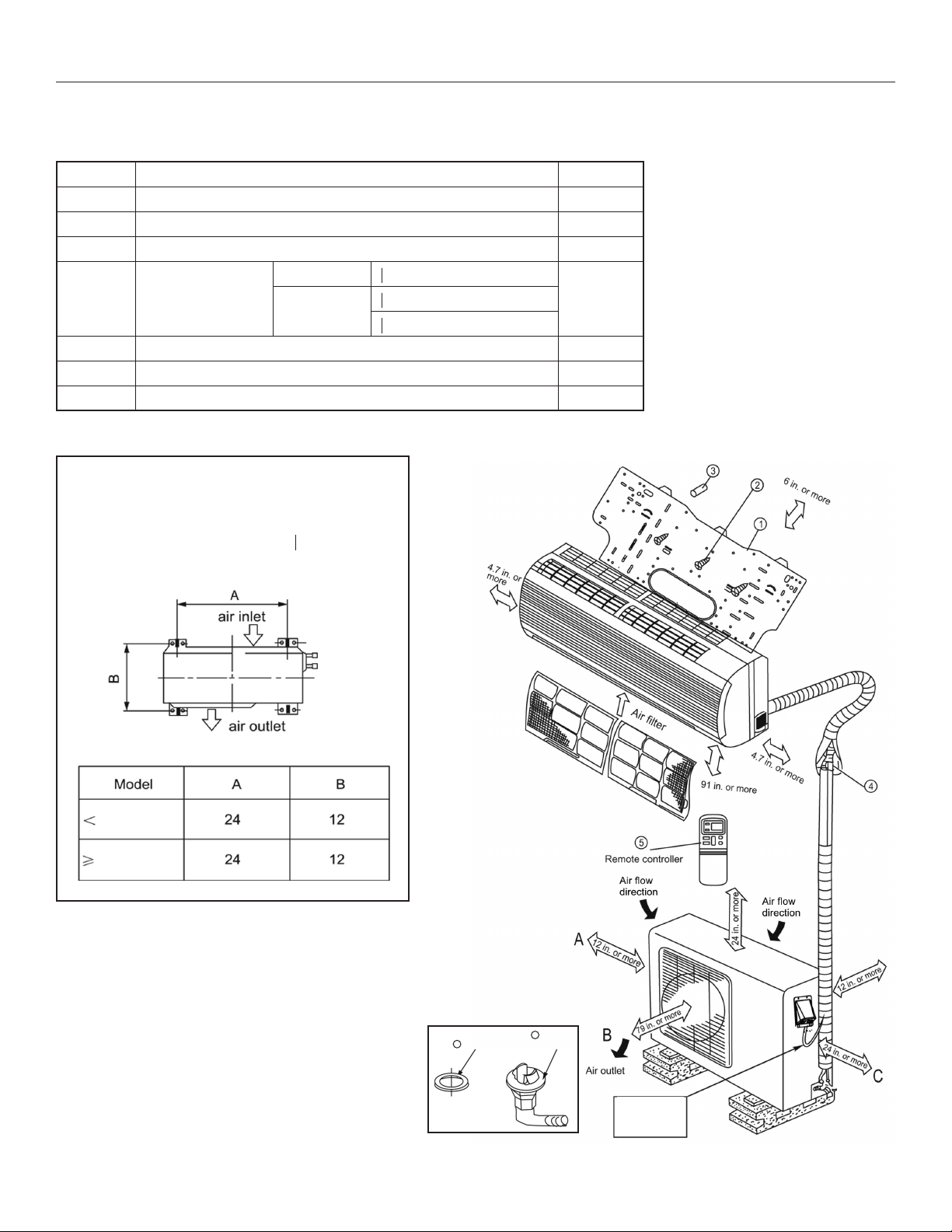
Installation Parts
Please install the accessories attached with unit correctly according to this installation manual.
Part No. Name of Part Quantity
1 Installation Plate 1
2 Mounting Screw A (ST3.9x25-C-H) 8
3 Anchor 8
Liquid side o 1/4"
4 Refrigerant Pipe
o 3/8" (<12,000 Btu/h)
Gas Side
o 1/2" (≥12,000 Btu/h)
5 Remote Controller 1
6 Seal* 1
7 Drain Elbow* 1
* See outdoor installation instructions
Anchoring the Outdoor Unit
• The outdoor unit should not be exposed to
strong winds
• Anchor the outdoor unit with
anchor bolts
o1/4" or
5/16"
**Cautions on remote
controller installation
• Keep the remote controller at
least 3 feet from the nearest
TV set or stereo equipment
to advoid possible electronic
interference.
• Do not leave the remote
controller in a place exposed
to direct sunlight or close to
a heating source, such as a
stove.
• Ensure that the positive and
negative poles are correct
when inserting batteries into
the remote controller.
12000Btu/h
12000Btu/h
Note:
1. Be sure sides A, B, and C are free from blockage/obstacles to allow sufcient clearance for
air ow and maintenance.
2. When the outdoor unit is higher than the indoor
unit, to prevent rain from owing inside, make a
“U-bend” trap in the line.
3. The illustrations are only sketches. Actual units
may be slightly different.
"
"
"
"
6
Seal
**
7
Drain
Elbow
U Bend
example
2
Page 4
SMA/SMH 09/12 INSTALLATION INSTRUCTIONS Heat Controller, Inc.
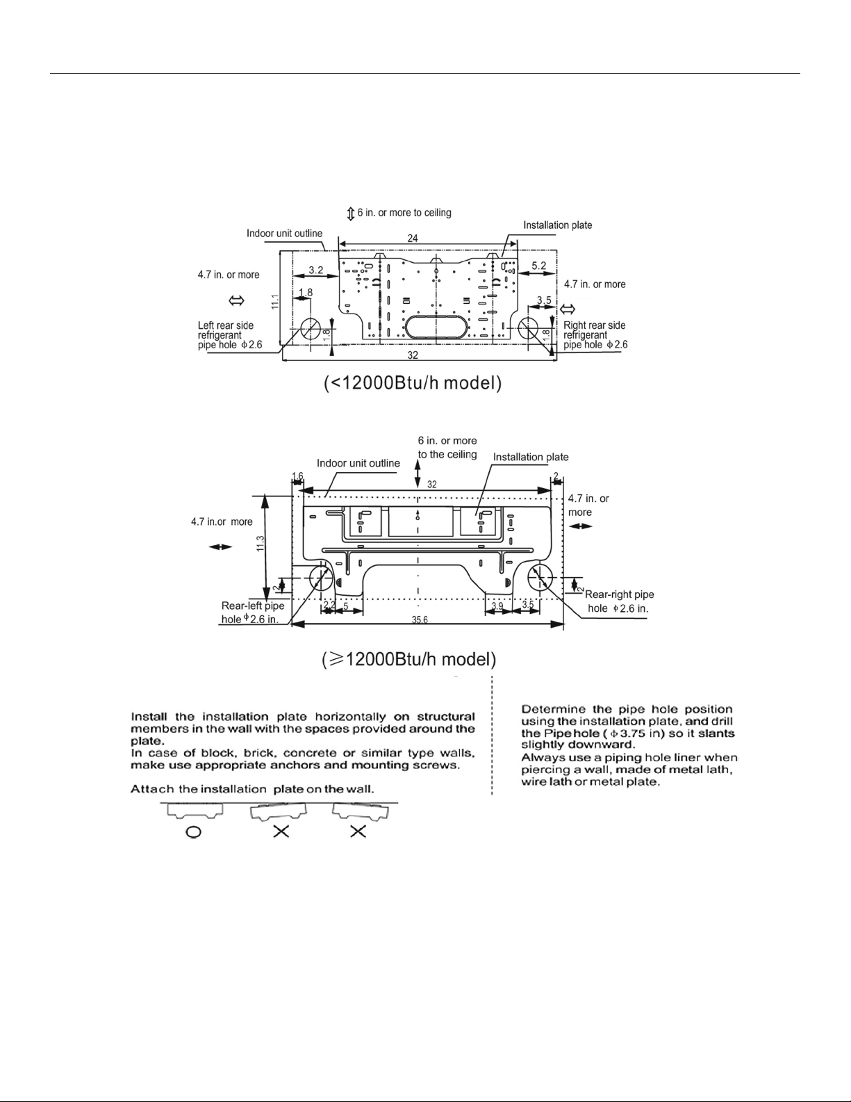
INDOOR UNIT INSTALLATION
1. Mounting Installation Plate and Creating a Wall Opening
Installation Plate and measurements (inches):
Clearance:
Clearance:
Clearance:
Clearance:
Clearance:
Clearance:
1. Attach the installation plate
A.
B.
C.
2. Creating a wall opening
A.
B.
3
Page 5
Heat Controller, Inc. INSTALLATION INSTRUCTIONS SMA/SMH 09/12
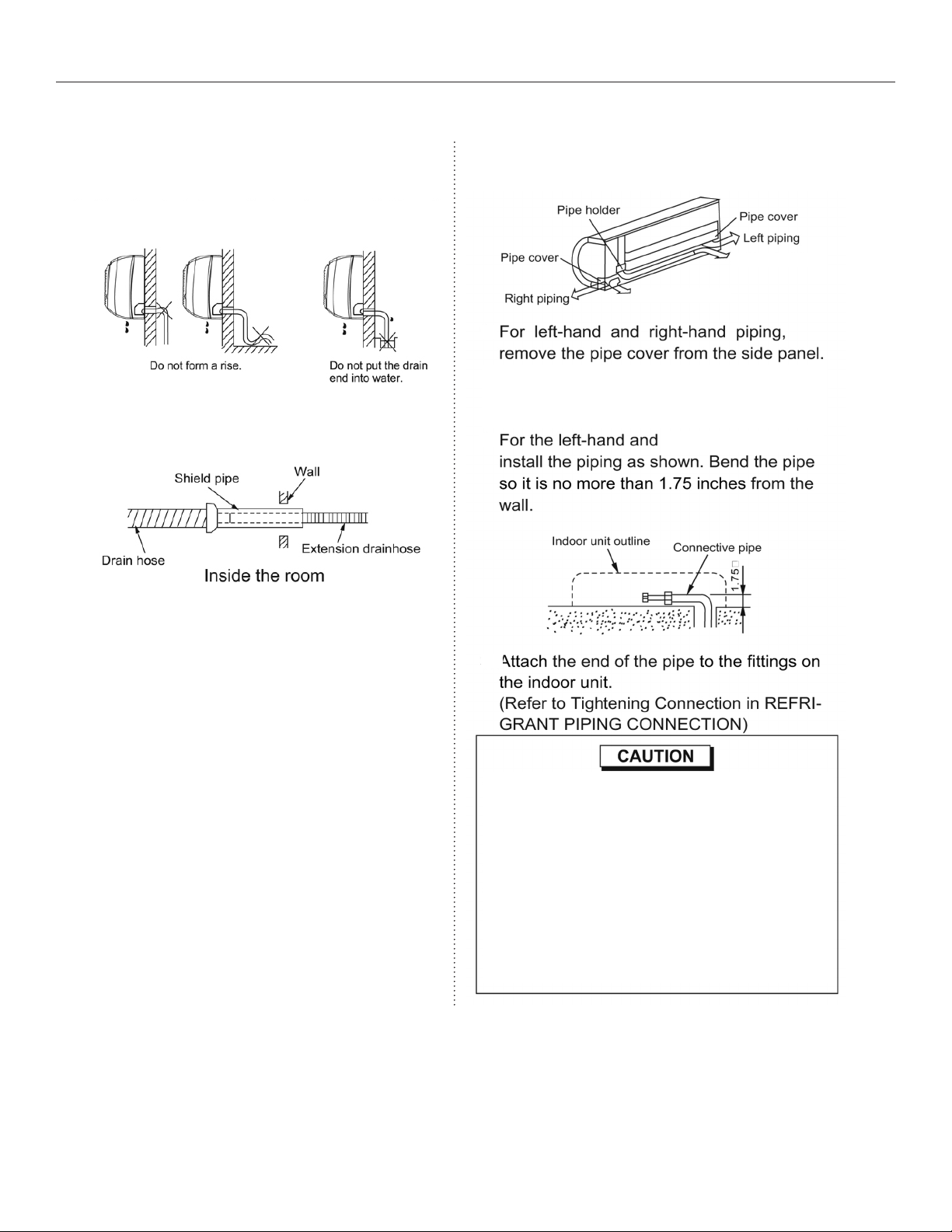
2. Line Set and Condensate Drain Line
1. Condenstate Drain
A. Run the drain hose sloping downward. DO
NOT install the drain hose as illustrated below.
B. When extending the drain hose, insulate
appropriately.
2. Line Set
A.
B.
Left rear piping
Right rear piping
left-rear-hand piping,
C.
• Connect the indoor unit rst, then the outdoor
unit. Bend and arrange the piping carefully.
• Do not allow the piping to loosen from the
indoor unit during installation.
• Be sure not to let the drain hose slack.
• Insulate both pipes.
• Do not allow the power cable and control cable
to be crossed.
4
Page 6
SMA/SMH 09/12 INSTALLATION INSTRUCTIONS Heat Controller, Inc.
3. Indoor Unit Installation
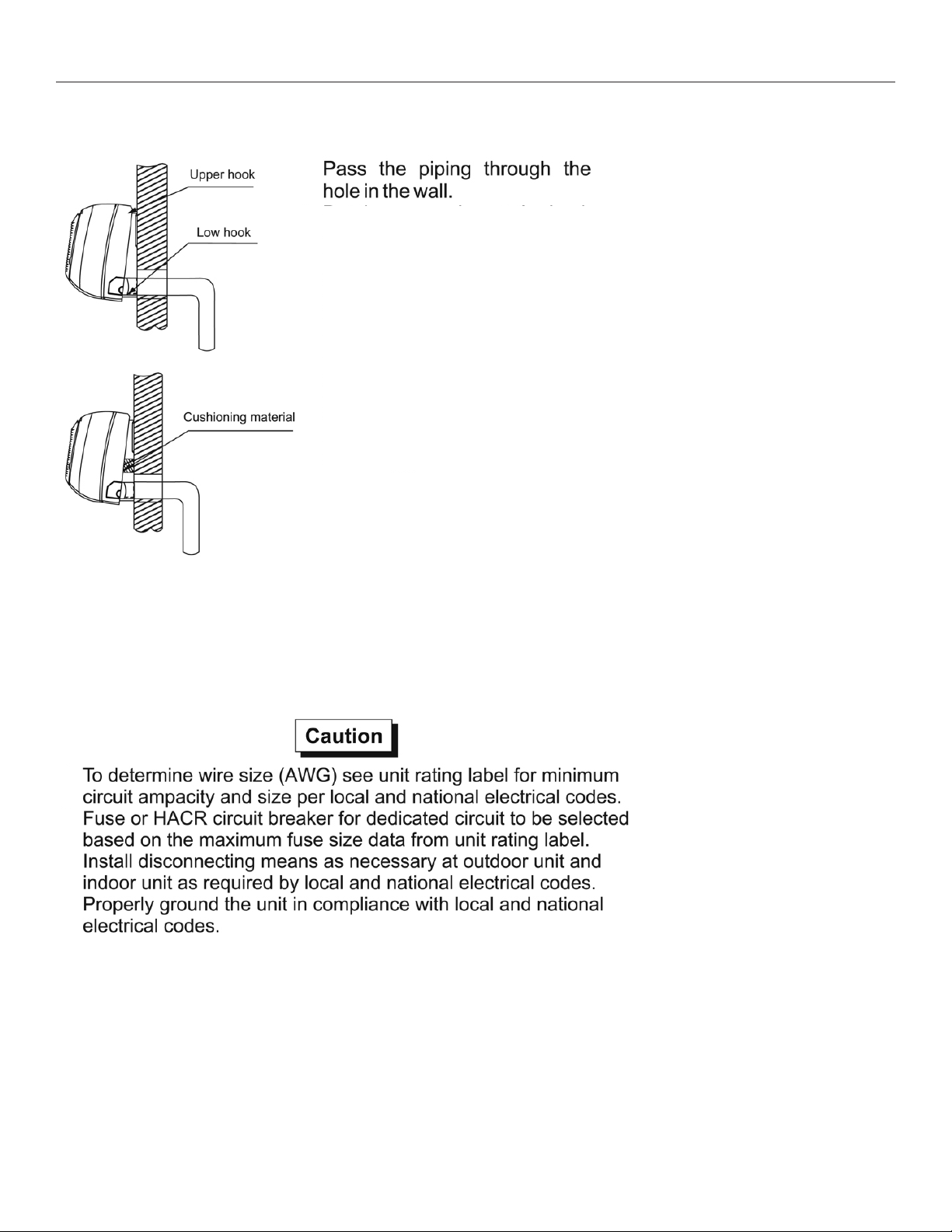
A.
B.
Place the upper lip at the back
of the indoor unit onto the upper hook of the installation plate.
Move the indoor unit from side to
side to see that is is secured onto
the hook of the installation plate.
C.
Push the lower part of the indoor
unit up to the wall. Then move
the indoor unit from side to side
and up and down to ensure it is
secured to the installation plate.
D. Piping can easily be installed by
placing a piece of foam between
the unit and the wall to assist in
holding the unit away from the
wall during installation.
4. Electrical Work
• Connect unit to a dedicated circuit.
• Refer to the unit’s rating plate from proper supply voltage.
A.
B.
C.
D.
E. All wiring to the unit and interconnecting between indoor and out-
door units must comply with local and national electrical codes.
F. Do not exceed the power code by splicing.
G. Voltage should be in range of 90%~110% of unit’s voltage.
H. The indoor unit is powered through the interconnecting cable. The
indoor unit requires no separate power source.
5
Page 7

Heat Controller, Inc. INSTALLATION INSTRUCTIONS SMA/SMH 09/12
5. Connecting Cables
A. Indoor/outdoor connections should be 18 AWG or heavier, SJOW cord. Check the rating plate for minimum
circuit to select wire size.
B. Open the panel, remove the electrical box cover by loosening the screw for (for <12000Btu/h models).
Remove the panel and screw covers, then loosen the screws and take down the frame (for ≥ 12000Btu/h
models).
C. Connect the wires to the terminals on the control board individually according to the outdoor unit connection.
D. Wrap the cables not connected with terminals with electrical tape so that they will not touch any electrical
components.
6
Page 8

SMA/SMH 09/12 INSTALLATION INSTRUCTIONS Heat Controller, Inc.
6. Piping and Wrapping
A. For the left-hand and right-hand piping, remove the rear
plate bushing from the left side of the rear plate.
B. Wind the line set, drain hose and wiring with tape se-
curely and evenly. Consult local and national electrical
codes for proper routing and placement of electrical
wiring.
C. When installing the indoor unit lower than the outdoor
unit, make a “u-bend” trap to prevent rain water from
running along the connecting pipe to the inside of the
building/room where the indoor unit is located.
wrap
line set.
Before wrapping electrical wiring with line set, consult local and
national codes for proper installation of line voltage wiring.
7
Page 9

Heat Controller, Inc. INSTALLATION INSTRUCTIONS SMA/SMH 09/12
OUTDOOR UNIT INSTALLATION
1. Outdoor Installation Precaution
• Install the outdoor unit on a rigid base to prevent noise and vibration.
• Locate the air outlet direction where the discharged air is not blocked.
Ensure there are no obstacles blocking the unit’s air ow.
• If the installation location is exposed to strong winds, place the unit length
wise along a wall or use shield plates to protect against high winds.
• If suspending the unit, the installation wall should be solid brick, concrete or of similar construction. If
not, reinforce the supporting wall. The connections between the bracket and wall and the bracket and
the air conditioner must be rm, stable and reliable. Consult all local and national building codes.
• If suspending the unit, follow the instructions provided by the bracket manufacturer.
2. Drain Elbow Installation
Fit the seal into the drain elbow,
then insert the drain elbow into the
outdoor unit’s base pan hole, rotate
90° to securely assemble them. To
discharge excessive condensate
from the outdoor unit when in heating
mode, connect the drain elbow to a
8
9
drain hose (locally purchased).
8
Page 10
SMA/SMH 09/12 INSTALLATION INSTRUCTIONS Heat Controller, Inc.
3. Refrigerant Piping Connection
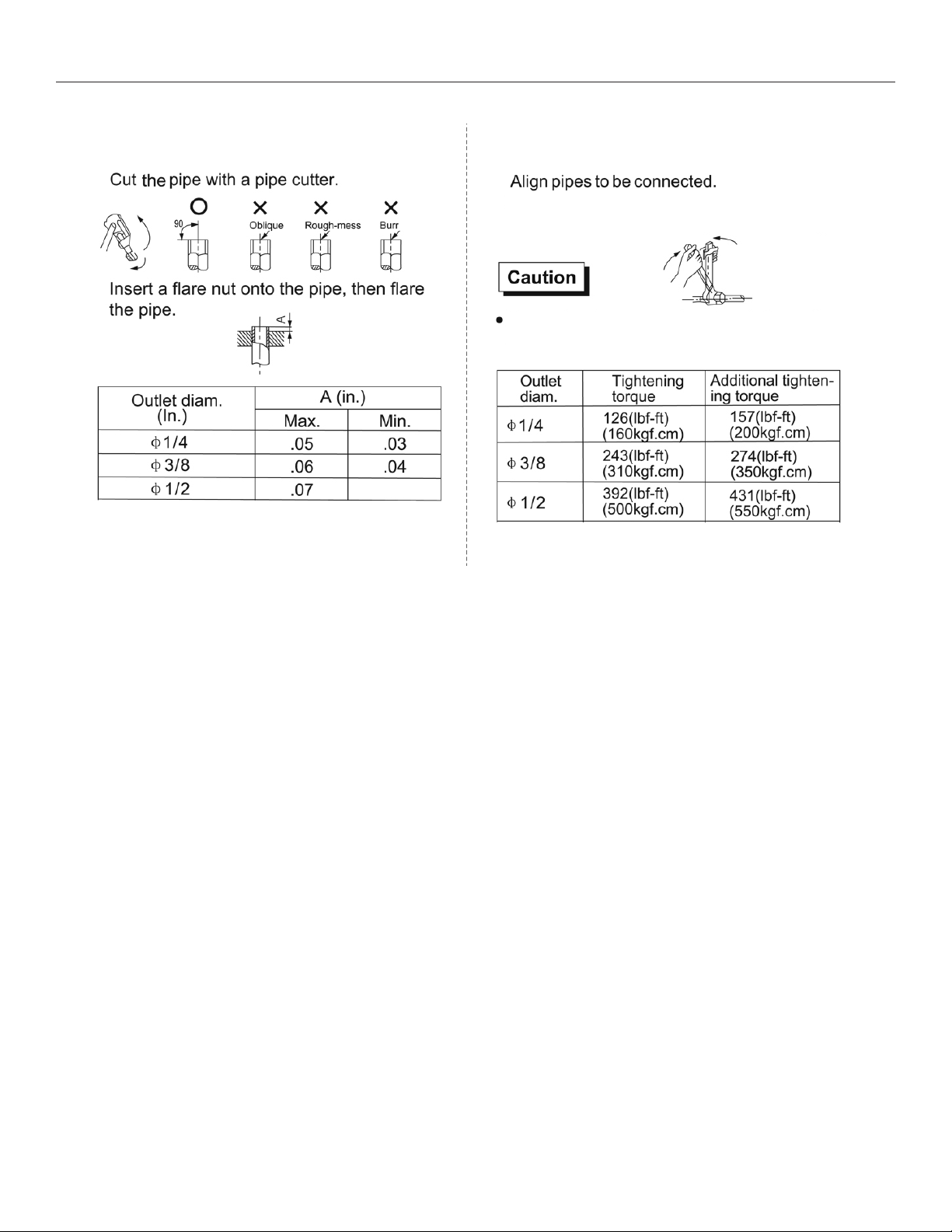
1. Flaring
A.
B.
.04
2. Tightening Connection
A.
B.
Hand tighten the are nut and then tighten it
with a spanner and torque wrench as shown.
Excessive torque can break the are nut. Ensure
the proper torque is adhered to in the chart below.
9
Page 11

Heat Controller, Inc. INSTALLATION INSTRUCTIONS SMA/SMH 09/12
4. Wiring Connection
A.
•
•
B.
•
•
C.
•
D.
•
E.
•
F.
Use a dedicated circuit. Use HACR break sized per
unit’s rating plate. Size wires according to minimum
circuit ampacity shown on the unit’s rating plate.
• Be sure to comply with local and national electrical codes while running the wire from the indoor
unit to the outdoor unit.
• Install disconnects fro the outdoor and indoor
units as required by national and local electrical
codes.
• Every wire must be connected rmly. Loose wiring may cause the terminal to overheat or result
in unit malfunction. A re hazard may also exsist.
NOTE: To prevent wire from loosening, secure
wires and/or cords under cord clamp.
10
Page 12
SMA/SMH 09/12 INSTALLATION INSTRUCTIONS Heat Controller, Inc.
AIR PURGE AND TEST OPERATION
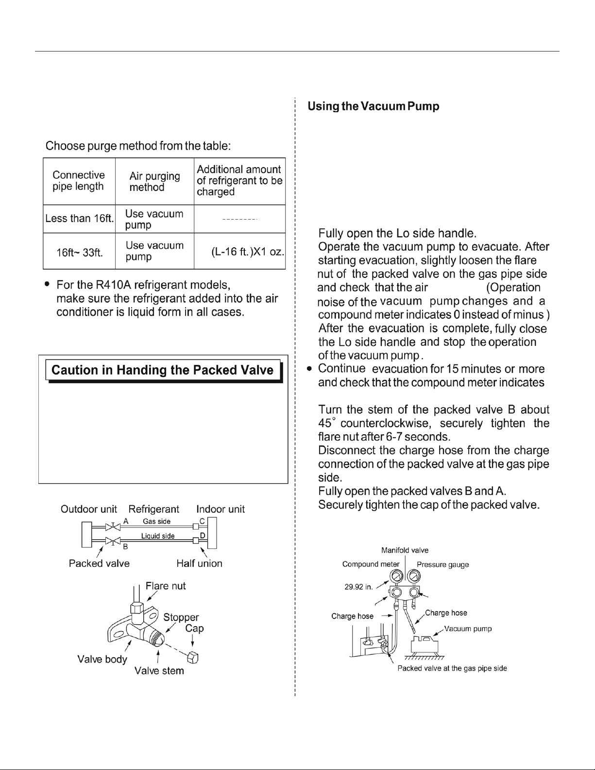
1. Air Purge
A.
Completely tighten the are nuts A, B, C, D.
Connect the manifold valve charge hose to the
charge port of the packed valve on the gas pipe
side.
B.
Connect the charge hose to the vacuum
pump.
C.
D.
where L=Length
is entering.
• Open the valve stem until it hits against the stop.
Do not try to open it further.
• Securely tighten the valve stem cap with a
spanner or wrench.
• Torque the valve properly:
Gas pipe side (0.38"): 23.5 N-cm (300 kgf-cm)
Liquid pipe side (0.25"): 12.56 N-cm (160 kgf-cm)
E.
-29.92 inHg.
F.
G.
H.
-
Lo Handle
Hi Handle
11
Page 13

Heat Controller, Inc. INSTALLATION INSTRUCTIONS SMA/SMH 09/12
2. Gas Leak Check 3. Test Operation
Make sure connections do not leak
with leak detector or soapy water.
A. Lo packed valve
B. Hi packed valve
C. End of indoor unit connection
D. End of indoor unit connection
soapy water.
Test the unit’s operation after completing gas leak
check at all are nut connections and complete
an electrical safety check.
A.
B.
C.
D.
E.
controlled by the remote controller to run in
cooling mode. Manual operation must be used
when the remote controller is disabled or when
maintenance is necessary.
12
The test operation should last about 30 minutes.F.
Page 14

08/2010
 Loading...