

Page 1
INSTALLATION
INSTRUCTIONS
SMALL DUCT HIGH VELOCITY:
SDAH 24 / 36 / 48 Fan-Coil Units
Heat Controller, Inc. • 1900 Wellworth Ave. • Jackson, MI 49203 • (517)787-2100 • www.heatcontroller.com
Page 2

Bulletin 100-155 — Installation Manual
GENERAL
The information on the following pages is to help the
installer save time by provide the best possible installation and ensure continuous trouble-free operation.
SCOPE
These instructions apply to the Heat Controller SDAH
Series. Installation instructions for the air distribution
system are covered in Bulletin 100-145. Before beginning any installation a detailed system layout must be
done in accordance with the System Sizing and Layout
Procedure, Bulletin 100-255 and the Component Layout
Instructions, Bulletin 100-250.
NOTICE TO INSTALLER AND EQUIPMENT
OWNER: RETAIN THIS MANUAL AT THE JOB.
FULL BUILDING INSULATION IS ESSENTIAL
FOR THE MOST ECONOMICAL OPERATION
GENERAL PRECAUTIONS AND SAFETY TIPS
Do not attempt to install or startup unit without first
reading and understanding the appropriate sections in
this manual.
Before operating, be sure the unit is properly grounded.
Installation should be in accordance with all local codes
and regulations and with the National Board of Fire Underwriters regulations. In case of conflict, local codes
take precedence.
All electrical wiring should be in accordance with the
latest edition of the National Electrical Code and all local codes and regulations. The unit is safety certified to
UL 1995 and listed with ETL.
Always install a secondary drain pan when an overflow
of condensate could cause damage.
HEAT CONTROLLER
INSTALLATION MANUAL
FOR
SDAH SERIES
TABLE OF CONTENTS
INTRODUCTION ................................................................... 1
OPTIONS ............................................................................. 2
UNPACKING ......................................................................... 2
LOCATION ............................................................................ 2
UNIT ASSEMBLY .................................................................. 3
Anti-Frost Switch Wires .................................................. 3
Fastening Modules Together .......................................... 3
Horizontal Installation ..................................................... 3
Control Box ..................................................................... 4
Secondary Drain Pan ..................................................... 4
MOUNTING ........................................................................... 4
Horizontal Platform Mounting ......................................... 4
Horizontal Suspended Mounting .................................... 5
DUCT CONNECTIONS ........................................................ 5
Supply Plenum ............................................................... 5
Return Duct .................................................................... 6
Multiple Returns .............................................................. 7
PIPING .................................................................................. 7
Condensate Lines .......................................................... 7
Refrigerant Lines ............................................................ 7
Water Connections ......................................................... 9
Coil Cleaning ................................................................. 10
WIRING ............................................................................... 10
Ventilation Speed Mode ............................................... 10
STARTUP ........................................................................... 10
Sequence of Operation ................................................ 10
Checking Airflow ........................................................... 11
How To Measure Air Flow ............................................. 12
How to Measure Static Pressure ................................... 12
Charging the System .................................................... 13
Low Ambient Control Kit ............................................... 13
R-410A Refrigerant ............................................................. 13
Maintenance ...................................................................... 14
Module Configuration Illustrations ........................................ 15
Blower Performance ............................................................. 15
Specifications ...................................................................... 16
PART NUMBERS
This manual does not always include the latest revision
letter when referring to SD part numbers. Refer to the
latest Price List and Spec Sheets for the current SD revision letter. For example, in SD-00x the ‘x’ indicates the
latest revision.
INTRODUCTION
Heat Controller offers a complete indoor comfort system
that includes an indoor air handling unit and small duct
system. The air handler and duct system were designed
to operate together to provide the proper airflow in every
installation. The conditioned air is supplied through a
© Copyright 2010 Heat Controller, Inc.
Page 3
Bulletin 100-155 — Page 2
series of 2-inch or 2 ½ inch ducts as a stream of air that
entrains and mixes the room air. This process of aspiration produces a more even temperature distribution in
the room.
The SDAH Series consist of a motor, blower wheel,
housing, controls, and an option of either a heat pump or
chilled water coil. For additional options, the SDAH
series features a latching mechanism for easy installation
of a Hot Water Coil module and/or Horizontal Return
Air Module. This series of air handlers must be installed
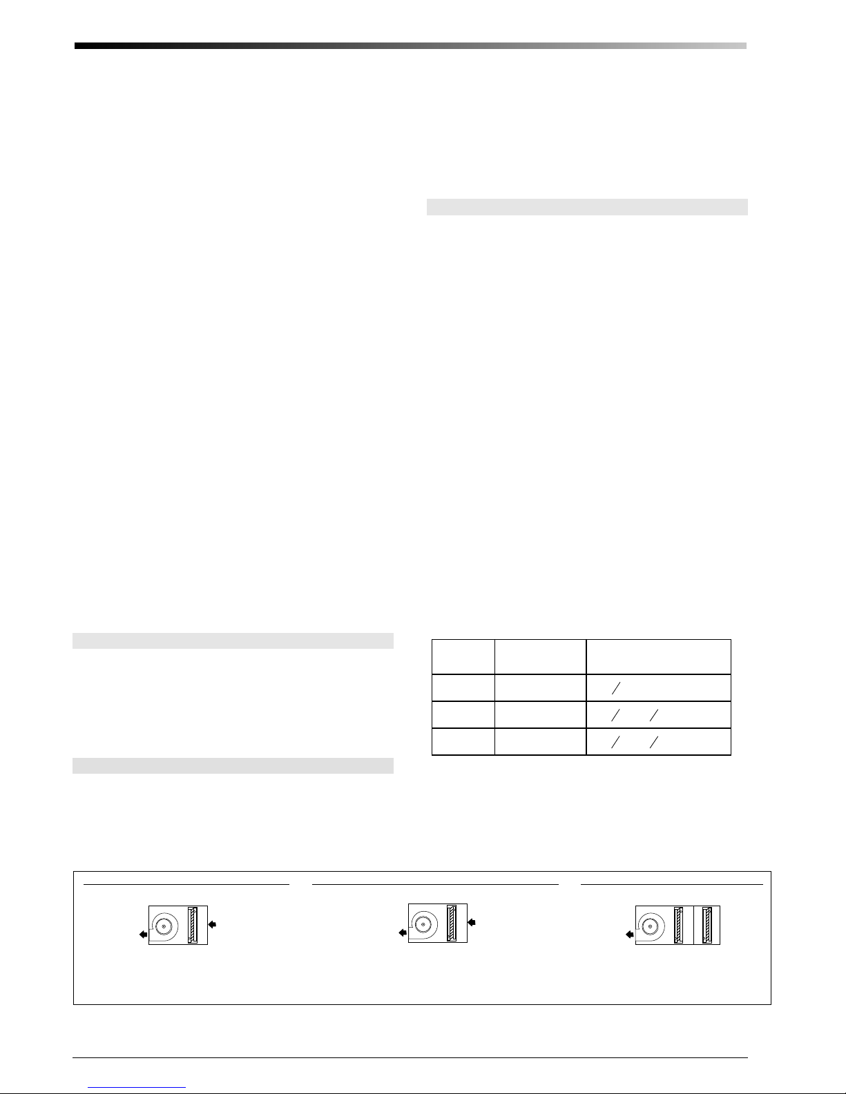
in the horizontal flow position to allow for proper drainage (See Fig. 1).
All insulated modules feature closed-cell insulation for
improved sound attenuation. There is no exposed fiberglass insulation.
SDAH module is available in three sizes: 24, 36, and 48.
The SDAH24 is sized for 1.5-2.0 tons, SDAH36 is sized
for2.5- 3 ton, and the SDAH48 is sized for a 3.5-4 tons.
The coils can be arranged to provide only the options
needed as shown in Figure 1 (with details on page 14).
Heating-only systems require the blower with a heat
pump coil, and a hot water coil. Cooling-only systems
include the blower with the heat pump coil used for
cooling. For heating and cooling use the refrigerant coil
with the hot water coil module or electric furnace.
Heat Controller blowers feature direct drive motors that
are located in the air stream. Each blower wheel is balanced to Heat Controller specifications. The blowers
feature a quick twist-and-lock motor mount for easy
maintenance (see page 16). The motorized blower assembly consists of the motor, which is mounted to the
inlet ring, and the wheel, which is fastened to the motor
shaft.
OPTIONS
Other options and modules are also available to add
additional features or to simplify installation. These include an electric duct furnace, hot water coil module,
and a horizontal return air module. Please refer to the
latest Heat Controller Catalog for information on these
and other options.
UNPACKING
Open each carton and inspect unit for visible signs of
concealed damage and notify carrier of any such damage.
All materials are sold FOB Factory and it is the responsibility of the consignee to file any claims with the delivering carrier for materials received in damaged condition.
LOCATION
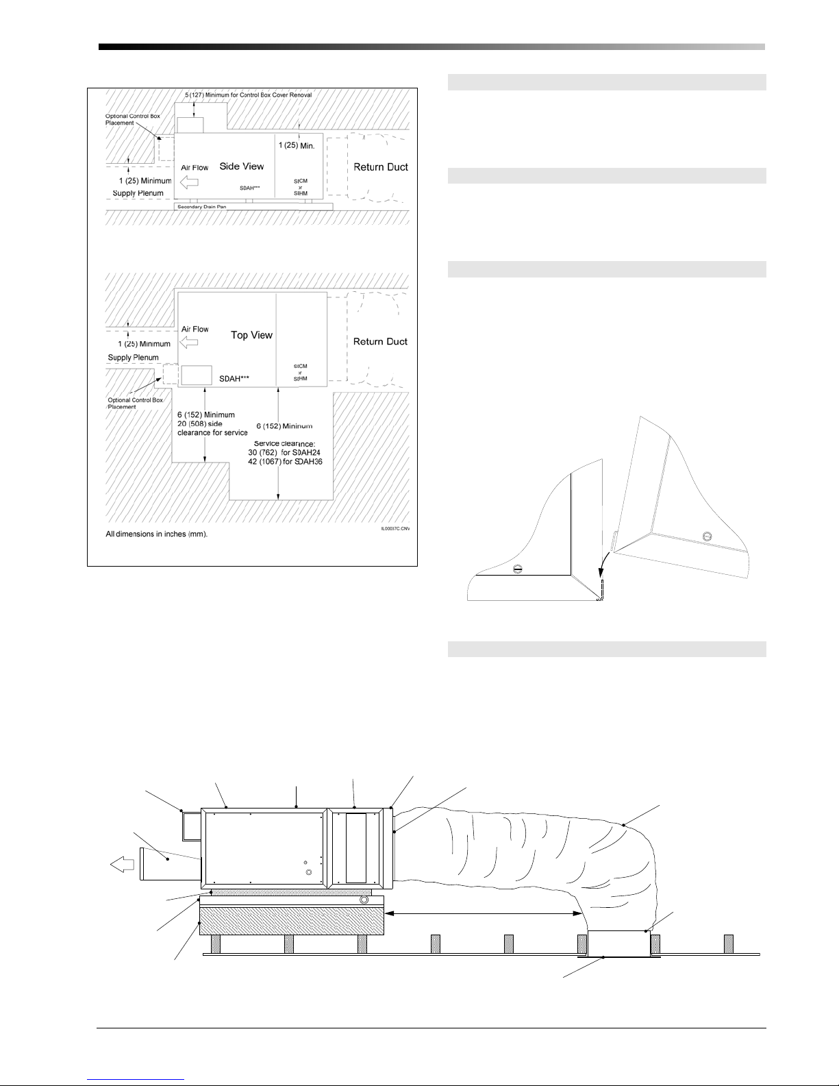
Design the system layout to minimize the number of
plenum elbows and fittings while keeping the supply
duct runs as short as possible. (See Bulletin 100-250,
Component Duct Layout Design). Provide minimum
clearance on both sides for servicing the unit as shown in
Fig. 2.
If installing the unit in an attic, avoid placing the unit
above a bed. The ideal location is above a central hall, a
closet, a bathroom, or any normally unoccupied space.
The unit can also be installed in a closet, crawlspace, or
basement. If the local codes allow, the unit may be installed in the garage provided the ductwork is well
sealed, especially the return duct. Although the unit is
not designed for outdoor use, it may be located outside
provided adequate weather protection is used; typically a
roof installation requires mounting on blocks with a
sheet metal cover or cap to protect the unit from rain and
extreme weather conditions.
Be sure to position the return air box and filter near the
unit allowing at least one 90° bend in the return duct for
proper acoustical performance (refer to figure 3 for a
typical attic installation). The section on Return Air
Ducts in the manual provides more details.
Table 1. Return Air Box Opening
Models
24 SD-01-24
36 SD-01-36
48 SD-01-48
Return Air Box
Part No.
Size of opening
inches (mm)
3
× 25 ½ (365 × 648)
14
8
3
1
× 30
14
8
2
3
8
× 30
1
2
24
(365 × 775)
(619 × 775)
All Heat Controller products are inspected prior to
shipping and are carefully packaged in individual cartons. Inspect all cartons prior to unpacking. Notify carrier of any damage.
Heating or Cooling w/ Heat Pump Coil
Horizontal
Flow
Figure 1. Basic Module Arrangement (refer to detail figures shown on Page 15)
© Copyright 2010 Heat Controller, Inc.
Heating or Cooling w/ Chilled Water Coil Only
Heat Pump C oil w/ Hot Water Coi
IL00010E.cvx
Page 4
Bulletin 100-155 — Page 3
A
UNIT ASSEMBLY
The units should be assembled horizontally. Refer to
Fig. 1 for your particular flow arrangement. If you use a
refrigerant coil, the anti-frost switch wires must be
routed to the control box during installation.
Anti-Frost Switch Wires
Remove the coil access panel and unravel the anti-frost
switch wires. Feed the wires through the bushing in the
motor partition panel and connect to the condenser terminal block on the SIB.
Fastening Modules Together
To fasten the modules together tilt the units to insert the
connection flange over the mating flange as shown in
Fig. 4. It may be necessary to squeeze the units together
as you are inserting the flange to compress the rubber
gaskets. If the hook flange has a small gap, use a large
flat bladed screwdriver to pry the gap apart. Secure the
modules together with the latches, compressing the
gasket further.
Figure 2. Minimum Clearances
All SDAH modules except are designed to fit through a
14-inch (356 mm) opening, typical of a joist spaced at
16-inch (406 mm) center distance. If no access is provided, an opening must be cut. It is suggested to use the
opening required for the return air box, especially in an
attic installation. The opening for the return air module
is listed in Table 1. If the joists or studs are less than 16inches (406-mm) center-to-center or running the wrong
direction it will be necessary to cut and header the joists.
Blower
Module
Control
Box
Plenum
dapter
(SD-61-xx)
Isolation
Pads
Secondary
Drain Pan
(SD-20x or 24x)
Platform
Figure 3. Typical Horizontal Attic Installation
(SDAHxx)
HP or CWC
(SDAHxxB)
or
(SDAHxxC)
Heating
Module
(SDCMxxH)
Figure 4. Module Flange Connection
All systems are to be installed in the horizontal configuration, with the air going from right to left when looking
at the connections (as shown in figure 1).
ReturnAir Adapter
(SD-104-xx)
Band (supplied with return air box)
Typical 10 foot (3.6 m) Return Duct
Use at least one 90° bend.
Return Air Box
(SD-01-xx)
Horizontal Installation
Return Air Duct
(SD-04-xx)
Band
IL00009.CVS
IL00039D.CVS
© Copyright 2010 Heat Controller, Inc.
Page 5
Bulletin 100-155 — Page 4
Control Box
The control box is shipped with all SDAH models. It can
be installed on either the discharge side of the blower
cabinet or on top of the blower cabinet, depending on
what is most convenient.
To install, first remove the two knockouts on the side or
top of the cabinet, where it will be installed. Mount the
control box using four (4) sheet metal screws as shown
in Fig. 5. Feed the wires from the anti-frost switch
through the hole and bushing nearest the side of the unit
and connect the leads to the AFS terminals on the SIB
(System Interface Board) condenser terminal strip. The
motor wiring harness will slip through the other hole.
Then simply connect the plug on the motor wiring harness. (For additional information see section on wiring.)
Figure 5. Mounting the Control Box.
Secondary Drain Pan
Where an overflow of condensate could cause water
damage, a secondary drain pan MUST BE INSTALLED.
Place the drain pan on the mounting base, platform or
angle iron support frame. Be sure to allow enough room
for the drain line and connection (refer to Table 3). The
assembled unit should be placed over the secondary
drain pan supported by rails with rubber pads for isolation to raise the unit above the 1.5-inch (38mm) sides of
the secondary drain pan.
Table 2 shows the secondary drain pans to be used for
horizontally mounted modules.
Table 2. Secondary Drain Pan Dimensions, inches (mm)
Unit
Part No.
Size
24 SD-20B
36 SD-27B
SDAH SDAH + Hot Water Coil
Dimensions
inches (mm)
29 × 31.5†
(737 × 800)
34 × 31.5†
(864 × 800)
Part No.
SD-20C
SD-27C
Dimensions
inches (mm)
29 × 43.75†
(737 × 1111)
34 × 43.75†
(864 × 1111)
Like the modules, all the secondary drain pans except
SD-24C will fit through the return air opening. For these
drain pans it will be necessary to fold the pans in order
to pass through the return opening.
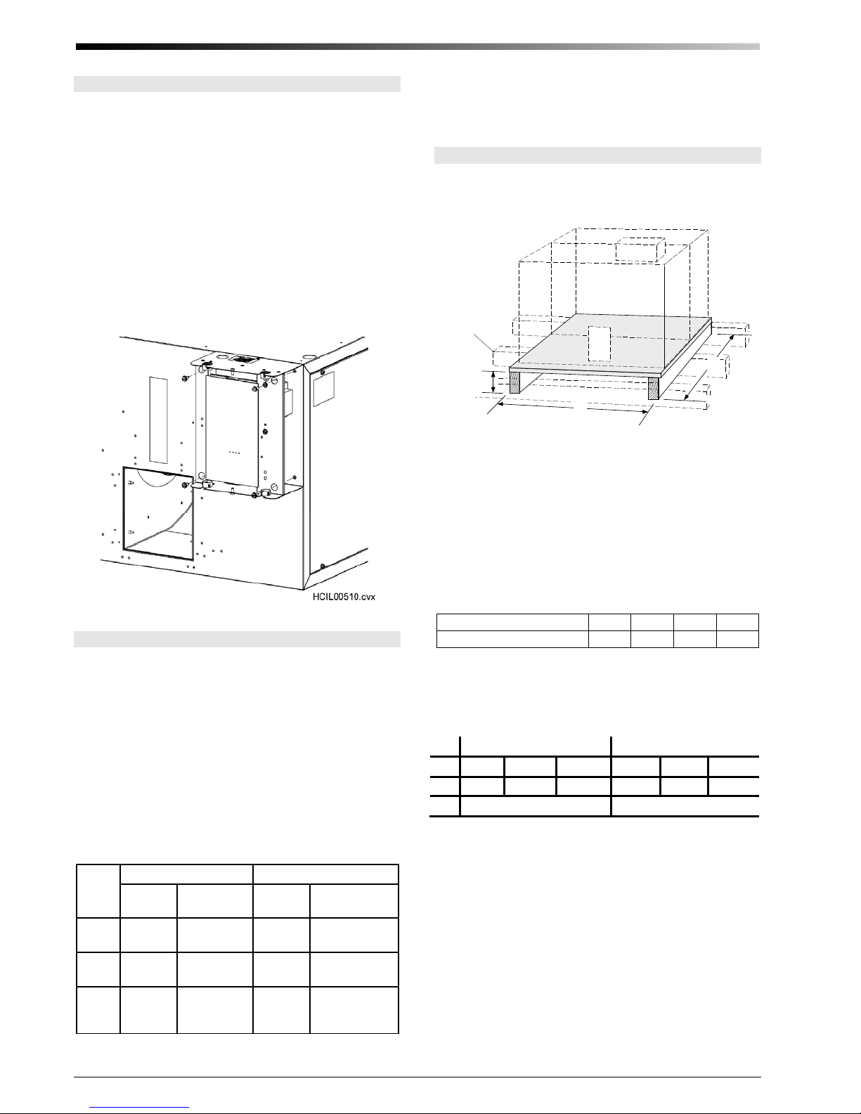
Horizontal Platform Mounting
It is easiest to mount the unit on a platform but care must
be taken to assure proper drain line pitch (see Table 3).
Rafter, Joist
or Floor
B
*
A
IL00036a.CNV
Figure 6. Typical Platform Installation
The platform height must allow for proper pitch of the
condensate drain lines — at least ¼ inch drop per lineal
foot (20 mm per meter). The platform can be built from
a sheet of ½ inch (13 mm) plywood and stud frame. Table 3 lists the maximum horizontal drain line run for
various framing materials and still provide adequate
drainage.
Table 3. Horizontal Distance of Drain Piping for Different
Framing Materials
Frame Lumber:
Max. Horizontal Run, ft. (m)
The platform size must allow for the number of modules
being used. For dimensions for minimum platform size
see Fig. 6.
Unit 24 36 48 24 36 48
A 25 (635) 30 (762) 38 (965) 25 (635) 30 (762) 38 (965)
B 26 (660) 38 (965)
Place secondary drain pan on platform and unit on top of
isolation pads inside of secondary drain pan. Be sure that
the unit is raised above the height of the drain pan side to
allow duct connections.
2 × 4 2 × 6 2 × 8 2 × 10
18 (5) 26 (8) 34 (10) 42 (13)
SDAH SDAH + Hot Water Coil
48
SD-24B
† NOTE — The drain fitting extends 7/8 inch (22 mm) beyond this dimension.
© Copyright 2010 Heat Controller, Inc.
42 × 31.5†
(1067 × 800)
SD-24C
42 × 43.75†
(1067 × 1111)
Page 6
Horizontal Suspended Mounting
CAUTION
Do not hang unit from top of unit cabinet as this could distort unit.
The modules can also be suspended from the ceiling or
rafters. A typical suspension method is shown in Fig. 7.
Screw four (4) “J” hooks into rafters. Suspend four (4)
chains from “J” hooks and attach eyebolts to chains.
Secure angle iron to eyebolts and place secondary drain
pan on top. Put isolation pads in drain pan, making sure
unit sits above sides of drain pan.
As an alternative, rest the unit on the angle iron supports,
and hang the secondary drain pan from the same supports. As above, install “J” hooks, chains, and angle iron.
Secure angle iron to eyebolts and put isolation padding
on angle iron.
Adjust the length of the eyebolts and chains so there is a
slight pitch towards the drain end.
HOOK
RAFTER
CHAIN
Bulletin 100-155 — Page 5
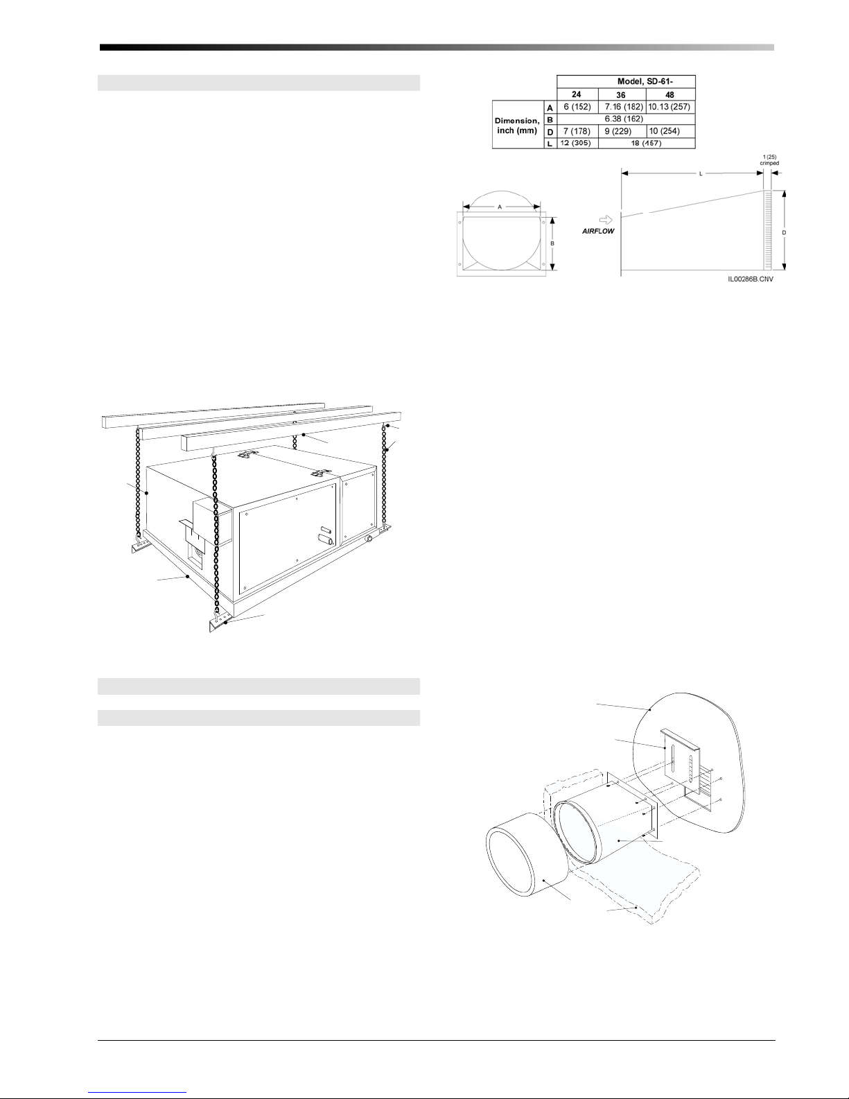
Figure 8. Round Supply Plenum Adapter Dimensions
Measure the motor amperage and use this to ensure the
200-250 CFM per nominal ton (27-34 L/s per nominal
kW) has been achieved. If elevated sound levels are noticed at the outlets and there is more that 250 CFM per
nominal ton (34 L/s per nominal kW), the airflow may
be reduced with the restrictor plate. Always measure the
system airflow by the motor amperage (see Table 4).
Refer to the airflow-amperage charts provided with the
blower.
UNIT
SECONDARY
DRAIN PAN
ANGLE IRON
Figure 7. Typical Suspended Mounting
IL00038C.CVN
DUCT CONNECTIONS
Supply Plenum
Heat Controller has a complete line of round plenum
adapters available as shown in figures 8. In addition, all
blowers include a restrictor plate to be installed between
the supply adapter and the unit. The purpose of the restrictor plate is to eliminate objectionable outlet noise
because the blower is delivering more air than required.
In most cases where the maximum airflow is required,
the restrictor may be omitted.
To attach the plenum adapter, first install the restrictor
plate. Then install the adapter with eight (8) sheet metal
screws as shown in Fig. 9. Sheet metal screws for installing both are provided with the blower.
The restrictor plate is used to set the system airflow (see
Fig. 10). The full open position corresponds to the highest airflow the installed duct system will allow. Set the
restrictor plate to the full open position and measure the
system airflow. The required system airflow is 200-250
CFM per nominal ton (27-34 L/s per nominal kW).
Note: Do not use restrictor plate to adjust
plenum static pressure. Adjust the restrictor
to the proper amperage. This will assure
proper airflow.
Attach the plenum to the adapter by inserting it over the
supply adapter. If using sheet metal duct, use three (3) or
four (4) equally spaced sheet metal screws or nails to
secure the duct to the supply adapter. Then tape around
the seam with UL 181A aluminum tape. Then wrap the
outside of the plenum adapter with the supplied blanket
insulation and secure the insulation seams with UL 181A
tape.
Blower
Module
Restrictor
Plate
Plenum Adapter
Plenum
Insulation Wrap
Figure 9. Supply Plenum Adapter Installation
IL00308.CVX
© Copyright 2010 Heat Controller, Inc.
Page 7

Bulletin 100-155 — Page 6
X
FRAMING
RETURN AIR BO
FILTER FRAME
FILTER
FILTER GRILLE
Figure 10. Restrictor Setting
Return Duct
Heat Controller supplies a return duct system but any
return duct system is acceptable provided the pressure
loss does not exceed 0.15 inches of water (37 Pa), including filters. The return duct should have at least one
90° bend between the unit and filter box to reduce sound
transmission directly from the unit.
The return duct system has a single return that includes
the return air box with filter, the return duct, and the
return air adapter (refer to Fig. 3). Multiple returns or
extra long returns are possible so long as the maximum
pressure loss is not exceeded.
The typical return duct is 10-foot (3 m) in length so it
may have to be cut to avoid bunching if the distance to
the unit is significantly less than 100-inches. The minimum length should be 7-feet (2 m). When given a
choice, the shorter distances should be avoided as this
may increase sound transmission from the unit.
Cut an opening for the return box as specified in Table 1.
For the 24 and 36, if the joists or studs are on 16-inch
(410mm) centers, there is no need to build a frame to
hold the return air box. Otherwise, it will be necessary to
construct a frame around the opening.
Center the return air box so the filter frame flange covers
all the gaps and make sure the flange is flush against the
wall or ceiling. Install the return air box against the
frame using nails or screws.
Screw holes are provided in the return air box. Use the
holes nearest the corners. The other holes are for mounting the filter grille. See Fig. 11.
IL00048.CNV
Figure 11. Return Air Box and Filter
Install filter frame into the return air box using four nails
or screws. Use the holes furthest from the corners. Insert
filter and hold in place by rotating metal clips. Close
grille and secure with clips.
Refer to Table 4 for correct Return Duct Adapter selection. Attach the proper return duct adapter to either the
Heating or Cooling Module. Then attach the return duct
to the adapter and to the return air box using the Q-bands
and Q-clips.
The return air adapter ships with an insulation blanket
that must be wrapped around the adapter. Tape the
seams with UL 181A aluminum tape.
Table 4. Return Duct Adapter
Blower Module +
Unit Size
24 - SD-104-24
36 - SD-104-36
48 SD-59-48 SD-104-48
Table 5. Approximate Amperages at Given Airflows
Unit Size
24
36
48
*multiply by 1.1 if 208V
† for more exact airflow use the chart included with the blower
Cooling Module
Airflow,
CFM (L/s)
600 (280)
500 (240)
400 (190) 1.4
800 (380) 3.2
700 (330) 2.9
600 (280) 2.7
1000 (470) 3.2
900 (425) 2.9
800 (377) 2.8
Heating Module
+ Cooling Module
SDAHxxx-A1
Amps
@230V †*
1.9
1.6
© Copyright 2010 Heat Controller, Inc.
Page 8

Bulletin 100-155 — Page 7
(ship
p
t
h
)
Multiple Returns
If more than one return is desired, Heat Controller has a
return plenum (HM) module. The HM module is available in three sizes: 24, 36, 48, and it includes a central
filter. The HM module is easily fitted to the air handling
unit and multiple return openings may be cut in the top
back or sides of the box. Refer to Bulletin 100-30, Re-
turn Plenum Module, for additional information.
PIPING
All piping must be in accordance with all local codes
and ordinances.
Condensate Lines
The primary drain pan condensate connection is a ¾inch (19mm) female pipe thread fitting and the secondary drain pan connection is a ¾-inch (19mm) PVC socket fitting. Elevate the unit so the condensate lines are
pitched at least ¼-inch per lineal foot (20 mm per meter). Trap the condensate line near the unit using U-trap
A00924-G03 as shown in Figure 12. In some cases it
may be necessary to wrap the condensate line near the
unit with insulation to prevent water condensation on the
outside of the pipe. In some climates or locations it may
be necessary to protect trap from freezing in the winter.
Refrigerant Coil Connections
Note
All refrigerant coils are shipped from
our factory pressurized with nitrogen.
They do not contain any refrigerant.
WARNING
To prevent injury to eyes, face away
from the Schrader valve when releasing
nitrogen gas.
The refrigerant coils are equipped with a Schrader valve
port to relieve the pressure and for factory testing purposes. It can also be used to check for leaks prior to installation. Unscrew the Schrader cap and press the depressor. If there is no nitrogen pressure present, the
coil may have developed a leak during shipment and
should be returned to the point of purchase for exchange. If pressure is present, then go ahead and relieve
the pressure in the coil by continuing to press on the
depressor. When all the pressure is removed, cut the
ends of the connections off.
Pitch ¼ inch per foot
(2 cm perm)
53/8
(137 mm)
IL00046a.cvx
U-TRAP (SD-00924-G03)
ed wi
Figure 12. Typical Condensate Trap
21/4
(57 mm)
SDAH modules
Do not trap the secondary drain line and do not terminate
line into the primary drain line. Run secondary drain line
so that any drainage will be immediately known without
causing damage to property. A typical location is to terminate the secondary drain line above a windowsill so
that the drainage splashes on the window. This will serve
as an indicator that there is a problem with the primary
drain. In cases where a secondary drain line cannot be
run, add a float switch or a micro switch with a paper
fuse.
Cut end of connection as shown.
Connection after the end has been cut off.
© Copyright 2010 Heat Controller, Inc.
Page 9

Bulletin 100-155 — Page 8
WARNING
To prevent injury, remove all pressure
from coil before removing connection
end caps.
CAUTION
When brazing, purge with nitrogen gas
to prevent the formation of oxides.
The refrigerant lines are copper sweat connections. The
liquid line is 3/8-inch (9.5mm) OD and the suction line
is 7/8-inch (22mm) OD. Refer to the condensing unit
manufacturer’s instruction for proper line sizing information based on distance from condenser.
Install a liquid line filter drier as close to the coil module
as possible to protect the evaporator from foreign object
debris. For attic installations or when using long line
sets, an optional moisture indicating sight glass should
also be installed between the filter-drier and expansion
valve, near the indoor unit.
All refrigerant coils require a thermostatic expansion
valve. The valve is shipped loose and should be attached
prior to charging. For replacement expansion valves,
refer to table 6. Always use new Teflon seals when replacing the TXV.
Remove side panels as shown.
Table 4. Expansion Valve Model numbers
Model
Heat Pump Coils
SDAH24B
SDAH36B
SDAH48B
Nominal
Condenser
2 to 2.5-ton
(7 to 9 kW)
3 ton
(10 kW)
3.5 to 4 ton
(12 to 13.6
Size
kW)
Valve Part Number
R-410a
A00808-013 2
A00808-014 3
A00808-015 4
Remove nut as shown.
Nom. Valve
Size
Attach and tighten lower connecting nut as shown.
Attach and tighten upper connecting nut as shown.
© Copyright 2010 Heat Controller, Inc.
Page 10

Bulletin 100-155 — Page 9
Route both the pressure and temperature tubes as shown.
Tighten the pressure tube nut as shown.
Secure bulb with cork tape as shown.
Water Connections
If you are installing the hot water coil, remove the side
coil access panel and cut away the insulation. Slide the
coil into the cabinet and secure with brackets supplied
with the hot water coil. Install the access panel after the
coil is in place.
The thermal measuring bulb is placed as shown. It
needs to be in contact with copper tube.
(a) Hot Water Coil
BLEED VALVE
(VENT)
IN
OUT
BLEED VALVE
(DRAIN)
(b) Chilled Water Coil
Figure 13. Water Coil Connections
© Copyright 2010 Heat Controller, Inc.
AIRFLOW
IL00054b.CVN
Page 11

Bulletin 100-155 — Page 10
All water connections are 7/8-inch (22mm) sweat connections. Sweat the water connections, than fill the system. Bleed the air from the coil by backing off the screw
inside the bleed valve for venting (Fig. 13).
If unit is in an unconditioned space below freezing, care
must be taken not to freeze the water in the coil. The best
method is to use a glycol-water antifreeze solution with a
freezing point below the coldest temperature expected.
After venting the chilled water coil, replace the access
panel and seal around the connections with the rubber
gasket provided.
Coil Cleaning
The coil should be sprayed with liquid detergent, or any
commercially available evaporator cleaner solution, thoroughly and rinsed thoroughly before installation to assure proper drainage of condensate from the coil. This
will eliminate blow-off and assure maximum coil performance. If not sprayed, approximately 50 hours of
break-in time are required to achieve the same results.
WIRING
WARNING
Disconnect electrical supply before
wiring unit to prevent injury or death
from electrical shock.
All electrical wiring must comply with all local codes
and ordinances. Blower module controls and components are bonded for grounding to meet safety standards
UL Standard 1995 and CAN/CSA-C22.2 No. 236 and
are listed by ETL.
Use a separate 1 ph - 230/208V – 60/50 Hz power
supply with a 15 amp breaker and appropriate wire
gauge per code.
The System Control Box comes standard with all SDAH
series blower/coil module. The control box is designed
to operate with a two speed motor with full speed being
used for heating and cooling. The second speed operates
at 50% of full speed and is used for ventilation mode
only. The SIB includes a 24-volt transformer, a capacitor, and the controlling circuit board. Refer to bulletin
100-180 for installation instructions for the SIB.
STARTUP
! IMPORTANT !
The most important step when installing
the small duct high velocity system is
making sure it has the correct airflow. Be
sure to record the amperage and voltage
of every system in order to verify the airflow through the unit. Also, measure the
airflow at each outlet to verify the airflow
in each room. Both methods are described later in this section.
Sequence of Operation
The sequence of operation depends greatly on the options installed and type of control thermostat used. Most
thermostats have a fan AUTO-ON switch. When the fan
switch is set to ON, the “G” circuit is closed and the
blower relay is energized. The indoor blower starts after
about a 20 second delay. The following paragraphs describe the sequence of operation when the fan is set to
AUTO. If the fan switch is set to ON, the sequence is the
same except the “G” circuit is always closed and the
indoor fan is always operating.
Cooling Cycle (Heat Pump). When the thermostat
calls for cooling, the “Y” and the “G” circuits are closed,
and a 24 V signal is sent to the compressor contactor in
the outdoor unit and fan relay in the indoor unit. After
about 20 seconds, the indoor blower starts. At the same
time, the compressor and outdoor fan also start. Depending on the control circuitry in the outdoor unit, there may
be a time delay before the outdoor unit starts. If the system was just turned off, the time delay could be as much
as five minutes. The cooling system is now operating.
For heat pump thermostats, setting the switch to ‘cooling’ immediately closes the “O” circuit, which is used to
energize the reversing valve solenoid if required by the
heat pump. Otherwise, the “B” circuit, which closes
when switched in heating, is used to energize the reversing valve solenoid. (Refer to the heat pump manufacturer’s instructions to see which mode the solenoid needs to
be energized – whether in heating or cooling.)
When the thermostat is satisfied, the 24 V signals are
opened and the outdoor unit stops. The indoor blower
continues to operate for about 40 seconds, then stops.
The system is now off.
Heating Cycle (Heat Pump). Setting the thermostat
to HEATING will automatically switch the reversing
valve solenoid. This setting closes the “B” circuit which
sends a 24V signal to energize the solenoid if required
by the heat pump. Otherwise the “B” circuit is not used
and the solenoid is not energized during heating.
When the thermostat calls for heating, the “Y” and “G”
circuits are closed, sending a 24 V signal to the compressor contactor in the outdoor unit and the fan relay in the
indoor unit. This starts the indoor blower and the outdoor compressor. There is a time delay of about 20
seconds for the indoor unit. The heating system is now
operating in stage one.
If the first stage does not satisfy the thermostat, the
second stage thermostat calls for more heat. This closes
the “W2” contacts and energizes the sequencer for electric heat (if installed). When the second stage thermostat
is satisfied, the “W2” circuit is broken and the sequencer
is de-energized. The electric heating system is now off.
When the first stage thermostat is satisfied, the 24 V
signals are opened and the outdoor unit stops. The indoor blower continues to operate for about 40 seconds,
then stops. The system is now off.
© Copyright 2010 Heat Controller, Inc.
Page 12

Bulletin 100-155 — Page 11
Heating Cycle (Electric Heat-Only). When the
thermostat calls for heating, the “W” and “G” circuits
are closed. The W circuit completes the 24V signal to
the sequencer in the electric duct heater, which cycles on
the electric heating elements. The G circuit completes
the 24V signal to the fan relay in the indoor unit, which
starts the indoor blower after a time delay of about 20
seconds. The heating system is now operating.
When the thermostat is satisfied, the 24 V signals are
opened and the indoor blower stops after about 40
seconds. At the same time the sequencer cuts the power
to the electric elements. The system is now off.
Note: Use a thermostat designed for electric
heat. A normal heating-cooling thermostat will
not close the “G” circuit on heating.
Ventilation Cycle. When the thermostat is satisfied
and the fan switch is set to “AUTO”, the “G” circuit is
open and the motor will slowly come to a stop.
Checking Air Flow
CAUTION
Do not operate blower with free discharge or low static pressures (below
.5-inch w.c. to prevent motor from overloading.
After the system is installed and before charging the
system, check for proper airflow. Record the position of
the restrictor plate, the plenum static pressure, and the
motor amperage. With this information, the amount of
airflow can be determined.
As a recommended further check on airflow, use a veloci-meter to measure the airflow from each outlet. The
most convenient instrument to use is a hand held vane
type velocity meter that fits directly over the outlet. The
Turbo-Meter (Davis Instruments Catalog No. DS105I07)
or equivalent meter will give a direct LED readout on
the Knots (FPM x 100) setting. For a 2-inch outlet, multiply the knots by 2 to get the CFM of the outlet. For a 2
½ inch outlet, multiply the knots by 2.37 to get the CFM
of the outlet. The CFM will have an accuracy of within
10%. (Multiply ‘knots’ by 0.94 to obtain L/s.)
By measuring and totaling the airflow of all outlets, the
total airflow of the system can be closely approximated
and provide a crosscheck for the airflow determined
from the motor amperage using the airflow-amperage
table that is shipped with all SDAH blower/coil modules.
Note: These tables are for the specific motor installed in each blower module. Be
sure the table used applies to the correct
model number that is shown on the table.
Use Table 5 to correct the airflow.
Check Static Pressure Measure the external static
pressure in the supply plenum at least two feet (610 mm)
from the unit and verify that it is within the allowable
range.
It is not necessary to measure the return duct static pressure unless it was field fabricated. The maximum return
static pressure (including filters) should be 0.15 inches
of water (37 Pa). If it is greater than 0.15 inches of water
column, add the return system pressure drop to the
supply plenum static pressure to get the total static pressure drop.
For example: If the supply static pressure is measured
to be 1.6 inches w.c. and the return system pressure drop
is 0.25 inches w.c, the total static pressure drop is: 1.6 +
0.25 = 1.85. In this case the static pressure is too high.
Check Motor Amperage. Remove the control box
cover and measure the current with an amp meter. This
should be measured on the purple wire between the control box and the motor with the letters “clmpmter”
printed on the wire. Compare this reading to the Motor
Amperage-Airflow table enclosed as a separate sheet in
the Blower Module carton.
Table 5. Airflow Troubleshooting Chart
Problem Probable Cause Remedy
Low Static, Low Amperage Restrictor set too low.
Blocked filters, restriction in return duct.
Low Voltage.
Blower Wheel not aligned properly.
Dirty blower wheel.
Low static, high amperage Large number of outlets.
High Static,
Low Amperage
Restrictor setting to high.
Restrictive duct system. Add outlets, add splitter vane in tee, reduce the number of
Open restrictor to table setting.
Clear restriction.
Check with local utility.
Center wheel inside of inlet ring. Position on shaft for 1/8
inch (3 mm) clearance from inlet ring.
Clean wheel.
Close restrictor to proper amperage, or
Add balancing orifices to outlets.
Close restrictor to obtain proper amperage.
tees and elbows in plenum, increase plenum size to 9”
equivalent, or
Open restrictor to proper amperage.
© Copyright 2010 Heat Controller, Inc.
Page 13

Bulletin 100-155 — Page 12
How to Measure Outlet Airflow
The Davis TurboMeter is the ideal instrument for measuring airflow for both the 2 and 2 ½ inch round outlets.
This instrument can be used to determine how much air
duct leakage is in the system by comparing the total airflow using the turbo meter to the motor amperage chart
that comes with the SDAH.
How to Measure Static Pressure
Measure the supply plenum static pressure at least 18inches (457mm) from the unit, but before any tee or elbow. A distance of between 2 and 3-feet (0.6 to 0.9m) is
best. Use an inclined manometer capable of reading at
least 2.5 inches of water column (622 Pa), such as
Dwyer Instrument’s model 109 manometer. Be sure to
zero the scale and level the manometer.
A magnehelic gauge that measures up to at least 2.5
inches of water may also be used.
Use a metal tube, typically ¼-inch (6mm) diameter, to
measure the static pressure. Determine where you want it
and cut or punch a small hole in the duct. Make the hole
the same size as the metal tube to prevent leakage. Insert
the metal tube 1-inch (25mm) so that the tip of the tube
is flush to inside wall of the duct and perpendicular to
the air stream as shown in Fig. 14.
Attach the metal tube to the manometer using a rubber
hose (usually supplied with the manometer). Record the
pressure.
Note: If the tube is not perpendicular to the air stream,
the reading will be in error. You will get a higher reading if
the tube is angled toward the air stream.
To assure an accurate measurement, follow the procedure listed below.
1. Slide the ON switch to the Knots position. This is
roughly equal to 100 ft-per-min.
2. Place the meter against the outlet with the fan centered over the outlet.
3. Record the KNOTS reading.
4. For a 2 inch outlet, multiply the KNOTS by 2.0 to
obtain CFM. For a 2 ½ inch outlet, multiply the
KNOTS by 2.37 to obtain CFM.
5. Use the Heat Controller Service Report Form to
record your system readings and to determine the
system total airflow.
Example:
A 2-inch round outlet reads 16.3 knots. Multiply 16.3 by
2 to obtain 32.6 CFM.
Repeat this for each outlet in the system and add them
together to determine the total CFM. This value can
then be compared to the blower amperage charts to insure minimal air leakage.
Figure 14. Measuring Plenum Static Pressure
In the absence of a manometer you can build a simple
but less accurate manometer in one of two ways. One
way is to use a short piece of ruler or yardstick and clear
plastic tubing as shown in Fig. 15.
© Copyright 2010 Heat Controller, Inc.
Figure15. U-Tube Manometer
Page 14

Bulletin 100-155 — Page 13
Charging the System
Charging
–
Cooling Mode. DO NOT VENT
REFRIGERANT TO THE ATMOSPHERE!! It is a
violation of federal law and in some cases local ordinances also. Always use a refrigerant recovery or recycling device.
The following procedure is only valid for charging the
system during the cooling mode.
To check for proper charge record the refrigerant pressures and temperatures. Check the refrigerant charge by
measuring the amount of sub-cooling (or ‘approach’
temperature for some condensing units). If the outdoor
manufacturer does not have sub-cooling or “approach”
temperature charts, then be sure that the sub-cooling is
between 3 and 8 °F (2 to 5°C). For long refrigerant lines
or when the evaporator is above the condenser, the subcooling should be close to 8°F; otherwise, aim for the
low end of the range.
After the refrigerant lines and evaporator have been
carefully leak tested and evacuated, release the R-410a
operating charge in the condensing unit. The system is
now ready for refrigerant charge adjustment. If the coil
is equipped with a threaded TXV, always verify that the
threads are tight and do not leak.
Start up the system and check line voltage to assure it is
within acceptable limits for the system as dictated by the
condensing unit manufacturer. Run the system for 20 to
30 minutes to get reasonably stabilized conditions. Do
not attempt to adjust charge with outdoor temperature
below 75°F (24°C). An outdoor temperature of 75 to
85°F (24 to 29°C) is preferred.
If the system charge must be checked when the outdoor
temperature is below 75°F (23.9°C), block the condenser
coil until the head pressure is approximately equal to
what its charging chart specifies for an 85°F (29°C) day.
For heat pumps always check the charge in cooling
mode. If this is not possible because of low outdoor temperatures, charge the system in the heating mode, but
return later when the weather is warmer before the system is switched to cooling.
Charge and operate the heat pump in accordance with
these instructions and the instructions provided by the
manufacturer of the outdoor unit.
Charging a heat pump, by its nature, is more difficult
than a cooling-only refrigerant system. Quite often the
ideal charge for cooling is different than the ideal charge
for heating, making the system much more sensitive to
the amount of charge. In some cases, the compressor will
trip on high head pressure during the heating mode because it is overcharged if the system was charged during
cooling. Likewise, the system may cycle on the anti-frost
control because of a low refrigerant charge if the system
was charged during heating.
To compensate for this charge difference some outdoor
unit manufacturers have a charge compensator device
that stores charge while in heating mode. Unfortunately
there are no add-on devices to accomplish the same thing
and only a few (usually the most expensive) model lines
will have one. For this reason, it is often necessary to
compromise the charge.
Although the unit can be charged in the heating mode, it
is best to charge the unit during the cooling mode. Then
recheck the charge during the heating season to be sure
the system is not over charged.
Charging – Heat Mode. If the system is started up on
heating where the return air temperature is significantly
lower than the normal operating range of 65 to 75°F
(18.2 to 23.8°C), the suction pressure can be very low.
Operate the system to bring up the return air temperature, using auxiliary heat if necessary, before checking
system charge.
Typically, in the heating mode, a High Velocity System
will have a slightly higher discharge (LIQ.) pressure, and
in cooling mode a High Velocity System will have a
slightly lower suction (SUC.) pressure.
Some outdoor heat pump units include a manual highpressure switch. With the lower airflow and higher temperatures, the discharge pressure will typically run higher than a conventional system. It is important that the
system be operated at pressures below the trip pressure
of the high-pressure switch to avoid nuisance shut
downs. If this occurs, use a high head kit as described
below.
High Head Heat (Mild Weather Kit). When any heat
pump is operated during mild weather (temperatures
above 50°F [10°C]), the compressor may trip out on the
high-pressure limit. High Velocity systems are particularly sensitive to this since it operates with a lower airflow. Contact the manufacturer for more information.
To overcome this problem, install a control to cycle or
modulate the outdoor fan based on the compressor discharge pressure.
Sub-cooling Method. Many condensing unit manufacturers publish the amount of sub-cooling that the condenser will produce. Follow their instructions to charge
the unit. Typical sub-cooling values will be between 3
and 8°F (2 to 5°C). The unit should ALWAYS have
some amount of sub-cooling. To be sure there is enough
sub-cooling, especially if the unit is in a hot attic, check
the liquid line sight glass near the evaporator for bubbles
or measure the refrigerant liquid line pressure and temperature AT THE EVAPORATOR.
To measure sub-cooling use the following procedure:
Measure and record the liquid line pressure using an
1.
accurate refrigerant gauge. Record the corresponding
saturation temperature for this pressure.
Measure and record the liquid line temperature using
2.
an accurate metal or glass thermometer, or thermocouple. Tape or strap the sensor firmly against the
surface of the liquid line and cover with insulation.
© Copyright 2010 Heat Controller, Inc.
Page 15

Bulletin 100-155 — Page 14
3. Determine the sub-cooling with the following equation:
Saturated Temperature
— Liquid Line Temperature
= Subcooling
If the sub-cooling temperature at the condenser is low,
the system is undercharged and refrigerant must be added.
CAUTION
TO PREVENT DAMAGE TO THE
COMPRESSOR, DO NOT ADD LIQUID
CHARGE INTO SUCTION PORT.
If it is high, the system is overcharged and some refrigerant must be removed and collected in an empty refrigerant container.
DO NOT RELEASE REFRIGERANT INTO THE
ATMOSPHERE.
In some cases, such as in a hot attic, the liquid line will
pick up heat and lose its sub-cooling. This will be apparent if the sub-cooling at the evaporator is low. In these
cases, the liquid line should be insulated or strapped to
the suction line and both insulated. The same problem
can occur for long refrigerant lines; in this case, increase
the size of the liquid line to reduce the pressure drop.
CAUTION
TO MAINTAIN PROPER HEAT PUMP
OPERATION, DO NOT STRAP THE
LIQUID AND SUCTION LINES
TOGETHER FOR HEAT PUMP
SYSTEMS.
Superheat Method. Do not charge the system based
on superheat. Superheat measurements should only be
used to verify that the expansion valve is working properly.
The superheat should be between 8 to 12°F (4 to 7°C) at
the indoor coil. In some cases, particularly for the larger
capacity match-ups (i.e. 3 ton and 5 ton), a superheat of
15 to 18°F (8 to 10°C) is satisfactory. It is not uncommon to measure a superheat above 20 to 25°F (11 to
14°C) at the condensing unit.
Be aware that the superheat value is also dependent on
the outdoor air temperature. At lower air temperatures
the superheat will be higher than at higher air temperatures. If the condenser ambient temperature is between
75 and 85°F (24 to 29°C), superheat should be approximately 10 to 12°F (5 to 7°C). If the outdoor temperature
is between 85 and 105°F (29 to 40°C), superheat should
be approximately 8 to 10°F (4 to 5°C).
To measure the superheat, use the following:
Measure and record the suction pressure at the eva-
1.
porator outlet using an accurate refrigerant gauge. If
this is not possible, measure the pressure at the service port on the suction valve fitting at the condensing unit and add the estimated pressure loss in the
suction line between the condensing unit and evaporator. Record the corresponding saturation temperature for this pressure.
Measure the suction line temperature at the evapora-
2.
tor outlet using an accurate metal or glass thermometer, or thermocouple. Insert the thermometer under
the insulation on the suction line and tape firmly
against the surface of the suction tube.
Determine the superheat with the following equation:
3.
Suction Line Temperature
— Saturated Temperature
= Superheat
Charging by Gauge Pressures. It is not possible to
charge the system by gauge pressures. Gauge pressure
should only be used to verify the system is working
properly.
The Heat Controller System will show a lower suction
pressure during the cooling mode than a conventional
system. Generally, it will be 10 to 15 psi (70 to 100 kPa)
less. For example, a normal suction pressure for the Heat
Controller System
will be about 130 psig (898 kPa) with
an 85 to 95°F (29 to 35°C) outdoor temperature. Expect
lower pressures when the outdoor temperatures are lower.
The head pressures should be similar to a conventional
system when in the cooling mode.
Using a Low Ambient Control Kit
Since a small duct high velocity system operates at colder coil temperatures (in cooling mode), an anti-frost
switch is installed on the coil to prevent coil freeze-up.
In certain instances, such as when the outdoor ambient
temperature is low, the condensing unit will cycle on the
anti-frost switch. This may reduce the cooling capacity
at a time when the cooling load is still fairly high. To
provide better control and comfort, install a low ambient
control on the condensing unit. Typically, a low ambient
control is necessary when operating the unit at outdoor
temperatures below 80°F (26.6 °C), especially for a 5ton nominal capacity system.
These controls come in different configurations such as
the Hoffman Controls Corp. series 800AA-head pressure
control. This control modulates the outdoor fan to maintain a minimum liquid line temperature. Other controls
may cycle the fan on/off. In either case check with the
outdoor unit manufacturer to determine what controls are
compatible with the outdoor unit.
© Copyright 2010 Heat Controller, Inc.
Page 16

Maintenance
When service is required to the motor or the wheel, the
entire assembly may be removed as a unit (see figure
16). The SDAH series units are accessible from the piping connection side of the unit. It is not necessary to
access both sides of the unit. Nor is it necessary to disconnect any module or ducting.
To remove the motor and blower wheel assembly, loosen the six (6) screws fastening the motorized blower
assembly to the blower housing. Twist the motorized
blower assembly counter-clockwise (CCW) and pull the
assembly away from the blower housing.
CAUTION
TO PREVENT DAMAGE TO THE
WHEEL BALANCE, DO NOT GRAB
THE ASSEMBLY BY THE WHEEL OR
SET THE ASSEMBLY DOWN SUCH
THAT THE WHEEL IS SUPPORTING
THE ASSEMBLY. ALWAYS SET THE
ASSEMBLY DOWN WITH THE WHEEL
ON TOP.
Bulletin 100-155 — Page 15
Once the assembly is removed, the proper service may
be preformed. If the wheel is to be changed, it may simply be removed from the motor shaft by loosening the
motor set screw and pulling the blower wheel off the
motor shaft. If the motor is to be changed, first the blower wheel must be removed as mentioned above, and then
the screws fastening the motor to the inlet ring must be
removed.
Figure 16. Removal of the Motorized Blower Assembly
© Copyright 2010 Heat Controller, Inc.
Page 17

Bulletin 100-155 — Page 16
Figure 17. Horizontal Configuration Chart
Blower Performance
External Static
Pressure,
in. water (Pa)
Model CFM (L/s) Amps CFM (L/s) Amps CFM (L/s) Amps CFM (L/s) Amps CFM (L/s) Amps
SDAH24x-A1
SDAH36x-A1
SDAH48x-A1
© Copyright 2010 Heat Controller, Inc.
1.0 (250) 1.25 (310) 1.5 (370) 1.75 (435) 2.0 (500)
760 (360) 2.3 700 (330) 2.1 640 (302) 2.0 550 (260) 1.7 450 (212) 1.5
1380 (617) 5.2 1300 (613) 4.9 1200 (566) 4.5 1090 (514) 4.0 950 (448) 3.6
1480 (698) 5.0 1430 (674) 4.4 1360 (642) 4.5 1220 (575) 4.0 930 (439) 3.1
60 Hz – 230V
Page 18

Bulletin 100-155 — Page 17
SDAH Specifications
Model No. SDAH24 SDAH36 SDAH48
Electrical Characteristics 208 – 230 Volts / 60 / 1 phase
Size, HP (kW) 1/2 (0.37) 1 (0.75) 1 (0.75)
Motor
Blower Wheel Nom. Diameter, in. (mm) 9.5 (241) 9.5 (241) 9.5 (241)
Blower Wheel Width, inch (mm) 3.75 (95) 5.0 (127)
Nominal* Air Flow Rate, cfm (L/s) 600 (283) 800 (377) 1100 (519)
Plenum Static Pressure, iwc, (Pa) 1.5 (373) 1.5 (373) 1.5 (373)
Sound Pressure Level
Minimum Plenum Size, ID, inch (mm) 7 (178) 9 (229)
Shipping Weight, lb (kg) 82 (37) 94 (43) 111 (50)
Overall Dimensions, in. (mm) H x W x D
Full Load Amps 3.3 4.8 4.8
Capacitor, mfd. 10 10 10
Speed, RPM 1625/800 1625/800 1625/800
dB(A) 56 56 58
NC 50 47 50
17.5 x 25 x 26
(445 x 635 660)
17.5 x 30 x 26
(445 x 762 x 660)
17.5 x 38 x 26
(445 x 965 x 660)
A/C or Heat Pump Coil Option
Model No. 24 36 48
Compatible Condenser Size, Ton (kW) 1.5-2.0 (5.3-7.0) 2.5-3 (8.8-10) 3.5-4 (12.3-14)
Net Face Area, ft
Tube diameter, in. (mm) 3/8 (9.5)
Number of rows 4
Fins per inch (cm) 14 (355)
Heat Pump
Condensate Connection, in. (mm) FPT 3/4 (19)
Refrigerant R-410A*
Suction line O.D., in. (mm) 7/8 (22.2)
Fin Type corrugated
Number of Circuits 6 6 6
Valve, R-410A, Part No. A00808-013 A00808-014 A00808-015
Liquid line, in. (mm) OD 3/8 (9.5)
2
(m2) 1.92 (0.178) 2.34 (0.217) 3.48 (0.32)
Chilled Water Coil Option
Model No. 24 36 48
Net Face Area – sq. ft. (m
Water Coil
Water Connection Size, ODF Sweat – in. (mm) 7/8 (22.2)
Condensate drain connection size, FPT – in. (mm) 3/4 (19)
Tube Diameter – in. (mm) 3/8 (9.5)
No. of Rows 6
Fin Density – fins/in. (fins/m) 15.5 (610)
2
) 1.921 (0.178) 2.338 (0.217) 3.483 (0.324)
© Copyright 2010 Heat Controller, Inc.
Page 19

Bulletin 100-155 — Page 18
PAGE INTENTIONALLY LEFT BLANK
© Copyright 2010 Heat Controller, Inc.
Page 20

10/2010
 Loading...