

Page 1
INSTALLATION &
OPERATION MANUAL
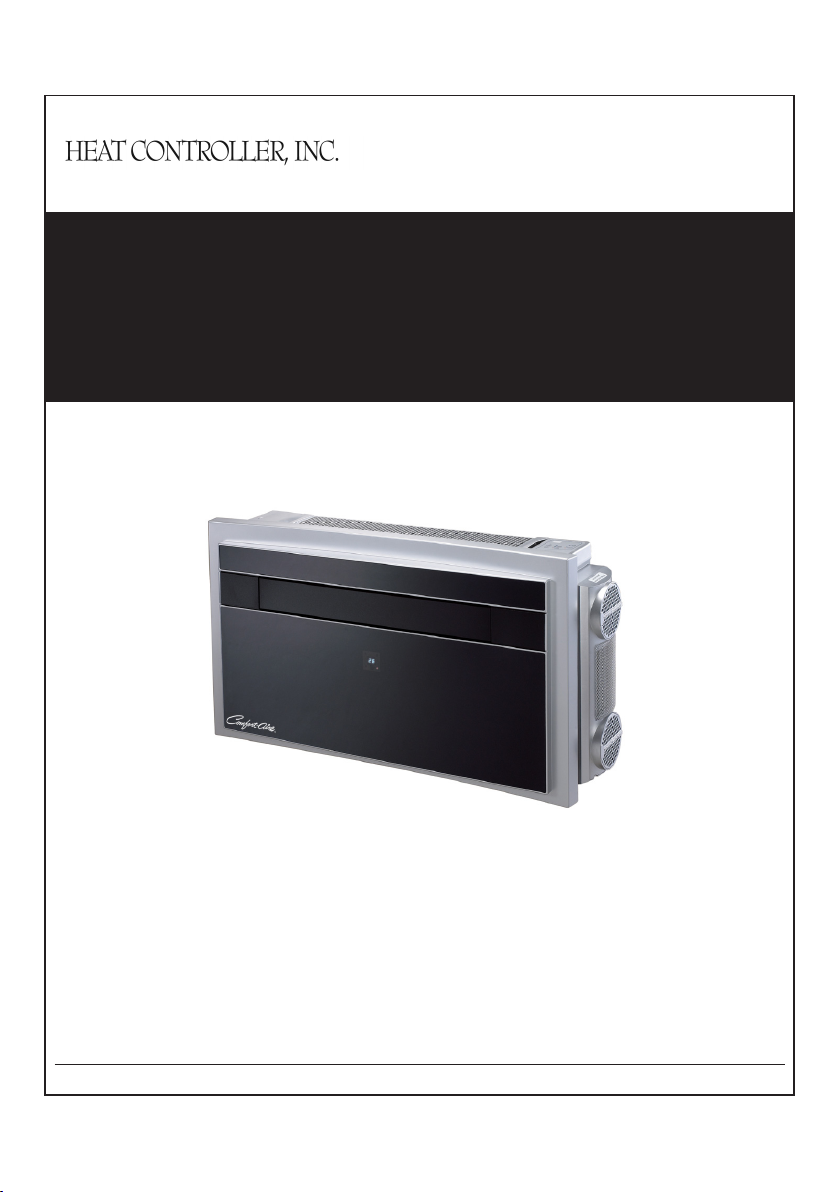
Packaged Thru-the-Wall Heat Pump
RPHE-093G Series
Heat Controller, Inc. • 1900 Wellworth Ave. • Jackson, MI 49203 • (517)787-2100 • www.heatcontroller.com
Page 2
Heat Controller, Inc. OWNER’S MANUAL Packaged Thru-The-Wall Heat Pump
Do not dispose this product as unsorted municipal waste.
Collection of such waste separately for special treatment is
necessary.
The figures in this manual may be different with the material objects, please refer
to the material objects for reference.
ALWAYS MAKE SURE THAT THIS MANUAL REMAINS
WITH THE RPHE-093G PACKAGED THRU-THE-WALL
HEAT PUMP OR OWNER OF THE PRODUCT.
READ THIS MANUAL BEFORE INSTALLING,
OPERATING, OR PERFORMING MAINTENANCE ON
THE RPHE-093G PACKAGED ROOM AIR HEATPUMP
UNIT.
……………………………………………………………………………………………………………
Page 3

Packaged Thru-The-Wall Heat Pump OWNER’S MANUAL Heat Controller, Inc.
PAGE
1.1
INTRODUCTION
1
1.2
SAFETY INSTRUCTIONS
1
1.3
RECEIVING THE GOODS
2
1.4
HANDLING
2
1.5
LIST OF ACCESSORIES
2
1.6
TECHNICAL FEATURES
3
2.1
POSITIONING THE UNIT
4
2.2
INSTALLATION TEMPLATE
4
2.3
DRILLING THE WALL
5
2.4
FASTENING THE BRACKET
6
2.5
INSTALLATION OF THE PIPES
6
2.6
FITTING THE GRATINGS
7
2.7
FITTING THE UNIT ON THE BRACKET
8
3.1
INTRODUCTION OF LCD ICONS
9
3.2
REMOTE CONTROL FUNCTIONS
9
3.3
STANDARD HEATING MODE
10
3.4
SUPER HEATING MODE
11
3.5
COOLING MODE
12
3.6
DRY MODE
13
3.7
FAN MODE
13
3.8
SLEEP MODE
14
3.9
AUTO MODE
15
3.10
TIMER OFF FUNCTION
16
3.11
TIMER ON FUNCTION
16
3.12
ON BOARD CONTROL FUNCTION
17
3.13
HEATING MODE AND SUPER HEATING MODE REFERENCE
18
3.14
FRESH AIR SYSTEM
19
3.15
INSTALLING AND CHANGING THE BATTERIES
19
3.16
MAINTENANCE
20
3.17
TROUBLE SHOOTING
21
3.18
INSTALLATION TEMPLATE FOR WALL DRILLING
22
INDEX
RPHE-093G PACKAGED THRU-THE-WALL HEAT PUMP UNIT
Page 4
Packaged Thru-The-Wall Heat Pump OWNER’S MANUAL Heat Controller, Inc.
1.1 INTRODUCTION
Do not dispose of any packaging until
installation of the unit is completed.
After having removed the packing, check
that all the contents are intact and complete.
See list of accessories. In the event of
missing parts, contact your retailer.
This unit has been designed to heat or cool
the air of a room and should only be used for
this purpose.
The manufacturer cannot be held liable for
damage caused to property or injury to
persons or animals due to incorrect
installation, regulation and maintenance or
improper use.
This unit contains R410A refrigerant. At the
end of its life, the disposal of this unit must
be in accordance with the regulation
governing the recycling of this product.
Please contact your local authority for
regulatory advice.
Do not switch on before having totally
assembled the unit and before installing in
its correct operating position.
Before starting the appliance, check that it is
correctly earthed, according to the
legislation in force in the country concerned.
1.2 IMPORTANT SAFETY INSTRUCTIONS
When using electrical appliances, basic safety
precautions should always be followed:
Do not place objects on the product or allow
objects to obstruct the inlet or outlet
openings.
Extreme care should be taken when any
product is used by, or near children and
pets, and whenever the product is left
operating and unattended.
Before operating the product remove the unit
from its packaging and check it is in good
condition.
Do not operate any product with a damaged
cord or plug, or after the unit malfunctions,
has been dropped, or damaged in any
manner.
Do not pull, remove or twist the power cord,
even if disconnected from the main electrical
supply.
Never place the power cord under a carpet
or rug or other location where it creates a
tripping hazard.
Do not attempt to repair or adjust any
electrical or mechanical functions on this unit
as this may void warranty.
Always operate the product from a power
source of the same voltage, frequency and
rating as indicated on the product
identification plate.
This unit is not intended for use in wet or
damp locations.
Do not place the unit near an open flame,
cooking or heating appliance, or hot surface.
Do not operate the unit in areas where
gasoline or other flammables are used or
stored.
Do not carry out any cleaning or
maintenance or access internal parts until
the unit has been disconnected from the
main electrical supply.
Do not alter the safety or regulating devices
without the permission and instructions of
the manufacturer.
Repair or maintenance work must be carried
out by an authorized servicer in compliance
with the instructions given in this booklet.
Do not alter the appliance. Since
hazardous situations could be created, the
manufacturer of the appliance will not be
liable for any damage or injury caused.
This instruction booklet is an integral part of
the appliance and should therefore be
carefully preserved and always accompany
the appliance in the event of transfer to
another owner or another installation.
1. GENERAL INFORMATION
1. GENERAL INFORMATION
……………………………………………………………………………………………………………
1
Page 5
Heat Controller, Inc. OWNER’S MANUAL Packaged Thru-The-Wall Heat Pump
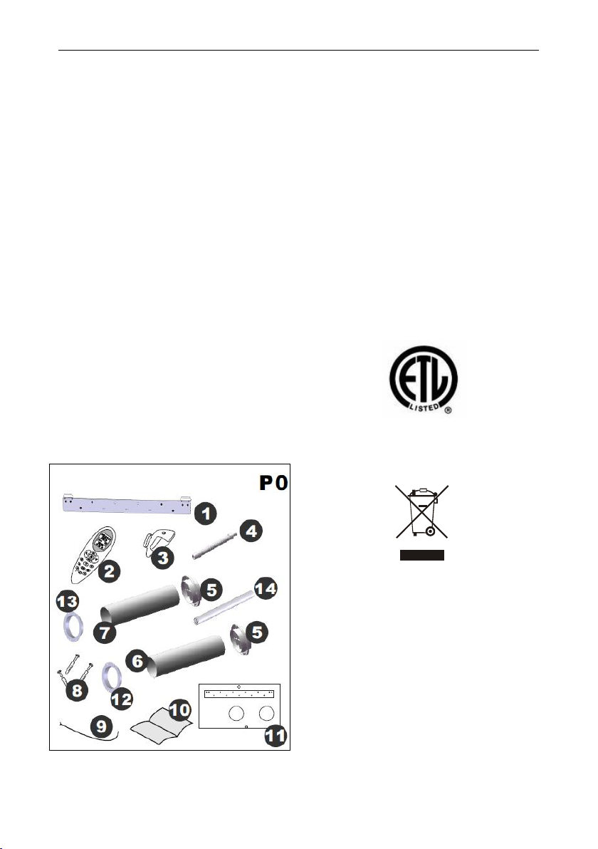
1. FASTENING BRACKET
2. REMOTE CONTROL
3. REMOTE CONTROL HOLDER
4. DRAINAGE PIPE
5. EXTERNAL GRATING x2
6. AIR DISCHARGE PIPE (6.30in)
7. AIR INTAKE PIPE (5.91in)
8. SCREWS KIT
9. GRATING FIXING CORD x2
10. INSTRUCTION MANUAL
11. INSTALLATION TEMPLATE FOR WALL
DRILLING (See page 19)
12. 6.30in RING
13. 5.91in RING
14. FRESH AIR PIPE
15. METAL GRILLE x2
This product has been manufactured to comply
with ETL.
Waste electrical products should not be disposed
of with household waste. Please recycle where
facilities exist. Check with your Local Authority or
retailer for recycling advice.
Any batteries used in the remote control
contain materials, which are hazardous to the
environment. They must be removed from the
remote control when they reach the end of
their life and disposed of responsibly.
1.3 RECEIVING THE GOODS
The unit is delivered in a protective packaging and
is accompanied by an instruction manual. This
manual is an integral part of the unit and should
therefore be carefully read and preserved. When
the unit is unpacked, please check that the unit
and accessory pack are complete and
undamaged.
1.4 HANDLING
Be fully aware of the weight of the unit
before attempting to lift it. Take all necessary
precautions to avoid damaging the product
or causing personal injury.
It is advisable to remove the packaging only
when the unit has been located in the
installation position.
Carefully remove the adhesive strips
positioned on the unit.
Packaging components must be disposed
correctly and not left within reach of children,
since they are a potential source of danger.
1.5 LIST OF ACCESSORIES (P0)
……………………………………………………………………………………………………………
2
Page 6
Packaged Thru-The-Wall Heat Pump OWNER’S MANUAL Heat Controller, Inc.
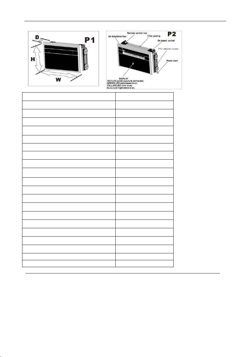
Model
RPHE-093G
Cooling capacity (Btu/h)
9300
Heating capacity (Btu/h)
9300
Electric heater capacity (Btu/h)
6800
Power input in cooling (W)
922
Power input in heating (W)
864
Power input for Electric heater (W)
2000
EER (Btu/W)
9.99
COP (Btu/Btu)
3.16
Air flow (ft3/m)
266
Fan speed setting
3+Auto
Dehumidification capacity *(gal/h)
0.217
Noise level indoor dB(A)
48.2
Noise level outdoor dB(A)
58.1
Power supply (V/Ph/Hz)
208/230/ 1 / 60
Refrigerant type
R410A
Refrigerant charged (lb)
1.43
Dimension HxWxD (in)
22.83 x 43.11 x 9.65
Weight (lb)
114.64
Inlet/Outlet hole diameter (in)
6.38
Fresh air pipe diameter (in)
1.97
1.6 TECHNICAL FEATURES (P1, P2)
ALL PERFORMANCE DATA AND SPECIFICATIONS ARE SUBJECT TO CHANGE WITHOUT NOTICE
STANDARD TEST OPERATING CONDITIONS IN COOLING AND DEHUMIDIFICATION MODE
Inside 80°F DB; 67°F WB
Outside 90°F DB; 75°F WB
STANDARD TEST OPERATING CONDITIONS IN HEATING MODE
Outside 47°F DB; 43°F WB
Inside 68.0°F DB;
……………………………………………………………………………………………………………
3
Page 7
Heat Controller, Inc. OWNER’S MANUAL Packaged Thru-The-Wall Heat Pump
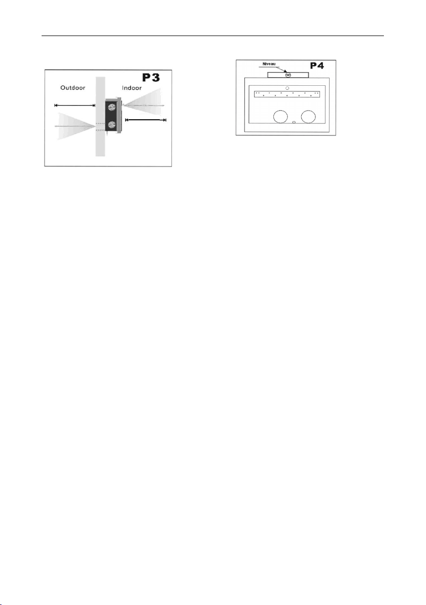
2.1 POSITIONING THE UNIT (P3)
To maintain the best performance from your unit
and to prevent breakdowns or hazards, you must
position it correctly. Please follow the guidelines
and instruction below in full, as failure to do so
could cause potential installation problems.
The unit must be installed on an exterior wall
that has access to outside air with a
minimum of 6-1/2 feet outside clearance.
The unit must be fitted leaving space around
the unit as illustrated in the installation
template.
The wall on which the unit is installed must
be sturdy and able to withstand the weight of
the unit.
After determining the best place for installation as
described above, please check to ensure that the
wall can be drilled in the chosen area without
interfering with other structures or installations
(beams, studs, pipes, wires, etc.).
Please also ensure that there are no obstacles on
the outside of the wall, which may obstruct air
circulation through the drilled holes, for example:
plants and their leaves, fences, drain pipes,
overflows and gratings, etc.). Any obstruction
could interfere with the correct performances of
the unit.
2.2 PAPER TEMPLATE (P4)
Fasten the template to the wall once the following
guidelines have been checked.
Do not drill any holes until you are
completely confident that there are no
obstacles in the area you wish to drill and
there are no obstructions, which could be
hidden by the construction of the wall, for
example: electrical wiring water, gas pipes
or supporting lintels or beams.
Ensure that a level is used, as the unit must
be level.
6-1/2 ft.
6-1/2 ft.
2. INSTALLATION
……………………………………………………………………………………………………………
4
Page 8
Packaged Thru-The-Wall Heat Pump OWNER’S MANUAL Heat Controller, Inc.
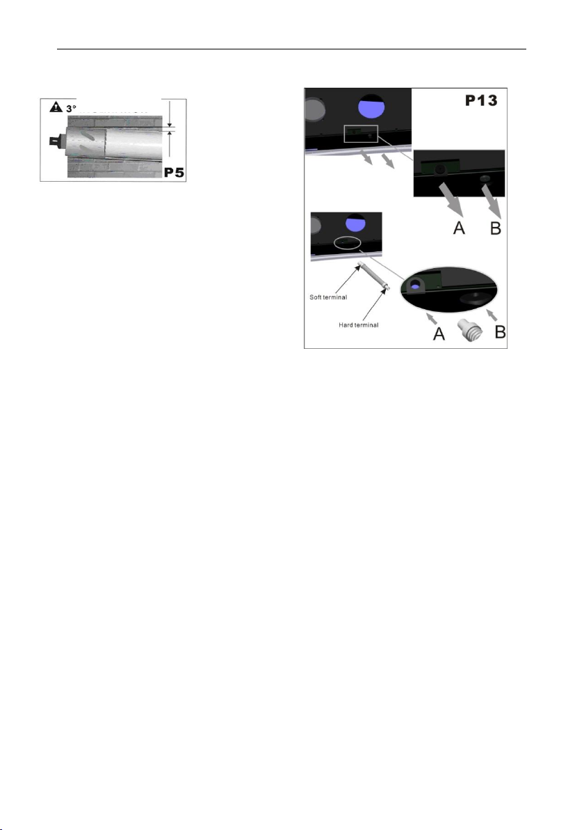
DRAINAGE HOLE (P13)
This unit has two alternative drainage methods to
manage condensate. Before installing the unit,
choose the most suitable method for your
application. There are 2 drain connections on the
unit, one is vertical to the floor which is named “A”
and the other one is horizontal to the floor which is
named “B” as shown in P13.
Method “A”: Employing this method allows the
condensate to drain to the outdoors. Begin by
drilling a hole through the wall measuring Ø1-1/4”
in the position shown on the paper template.
Drainage occurs by gravity, thus it is essential to
have a minimum downward slope of at least 3
degrees throughout the drain line’s length.
Connect the drain pipe (from soft terminal) to the
unit (hole “A”) after unplugging the black rubber
cap (see picture P13). Note: If method “A” is
used, do not unplug the black rubber cap for
drainage hole “B”.
Method “B”: Drainage occurs indoors to an
external floor drain, water tank, or sump pump.
Unplug the black rubber cap of system “B” (see
picture P13), then connect the drain pipe (from
soft terminal) to the unit hole “B” after unplugging
the black rubber cap. Place the hard terminal into
a water tank, floor drain, or sump pump. Note: If
system “B” is used, do not unplug the black rubber
cap for drainage hole “A”
2.3 DRILLING THE WALL (P5)
Please note: If you are drilling the hole above
ground floor level, please ensure while the holes
are drilled the outside area is supervised, until
drilling has been completed.
INTAKE AND OUTLET AIR HOLES, FRESH AIR
HOLE AND CONDENSATE DRAIN HOLE
This operation should be carried out using the
proper tools (diamond tip or core borer’s drills with
high twisting torque and adjustable rotation
speed).
Fasten the template to the wall taking care to
check the distance from the floor or ceiling.
Keep it horizontal by using a level.
Use a pilot drill to mark the centre of each
core hole to be drilled, and then use a
Ø6-3/8” core boring head to drill the two
holes for intake and outlet the air.
Use a pilot drill to mark the centre of the core
hole to be drilled, and then use a Ø2-1/8”
core boring head to drill the hole for fresh air.
Use a pilot drill to mark the centre of the core
hole to be drilled, and then use a Ø1-1/4”
core boring head to drill the hole for
condensate drain
All holes should be drilled in one operation.
For detail holes sizing and dimension for the
holes, please refer to the template on page
22.
It is recommended that the holes must have a
slightly downward slope of 3-5 degree to prevent
any backflow of water in the pipes.
INCLINE/SLOPE
2. INSTALLATION
……………………………………………………………………………………………………………
5
Page 9

Heat Controller, Inc. OWNER’S MANUAL Packaged Thru-The-Wall Heat Pump
2.5 INSTALLATION OF THE PIPES (P20)
After drilling the holes, the plastic pipes supplied
with the unit need to be fitted through them.
The pipe with a diameter of 6-5/16”in (air
discharge pipe) has to be fitted in the right
hole.
The length of the pipes should be same as
the depth of the wall plus 1/32”. Use a
normal hacksaw to cut the supplied pipes to
the correct length. Remember that the
installation must have the same slope as the
hole (minimum 3 degrees). NOTE:
Because the tube diameter is nearly the
same as the Ø6-3/8” core drill, the fit will be
snug. A rubber hammer and a small piece
of wood can be used to gently tap the tube
into the hole.
Please use the same instructions to fit the
left hand tube (fresh air intake pipe) using
the Ø5-29/32”in supplied pipe.
Insert the Ø5-29/32”in ring into the space
between the wall and pipe.
Insert the fresh air pipe (Ø1-31/32”) into the
Ф2-1/16” hole.
Please center the pipes into the holes in the
wall and insulate and seal their perimeters to
prevent air and humidity infiltration using
polyurethane foam and using plaster for
finishing the inside wall.
Ø5-29/32”
Ø6-5/16”
Ø1-31/32”
2.4 FASTENING THE BRACKET (P6)
Drill holes for anchoring the bracket to the
wall using the (6) holes shown in black on
the paper template.
The anchor bolts provided require (6) Ø5/16”
holes.
NOTICE: If the wall is not sturdy enough, it is
advisable to use extra anchor bolts using the
holes shown in grey on the paper template.
NOTICE: The wall should be inspected to
determine if the manufacturer provided bolts are
adequate for the installation depending on the
application. Due to building construction
variations, it may be necessary for the installing
contractor to use a different type of anchorage to
maintain the intended installation of the unit to the
wall. The manufacture is not liable in case of
underestimation of the structural consistency of
the anchorage made at the time of installation.
……………………………………………………………………………………………………………
6
Page 10

Packaged Thru-The-Wall Heat Pump OWNER’S MANUAL Heat Controller, Inc.
2.6 FITTING THE GRATINGS AND THE METAL
GRILLE (P7, P8, P9, P10) – CONT’D
If the external grating is accessible, to
prevent its removal, it is recommended to
fasten it to the wall with wall plugs and Ø1/4”
screws.
Once the grating is secure, slide the metal
grille inside the air discharge and the air
intake hose (1 per each hose) along the
cord.
Once the metal grille is adjacent to the
grating, use one of the special butterfly nut
screws provided to secure the metal grille to
the cord.
2.6 FITTING THE GRATINGS AND THE METAL
GRILLE (P7, P8, P9, P10)
To fit the external two gratings and the metal grille,
please proceed as follows:
Familiarize yourself with the fitting of the
flexible grating and the metal grille to the
tube before installation.
Insert the cords through the centre of the
grating. Note: The flexible grating fits on
the outside of the tube and the metal grille
fits inside.
Insert the supplied cord into the hole in the
center of the metal grille (see P9). Then
insert the supplied cord into the hole in the
center of the grating (see P9). Fold the outer
grating in half grasping the cord with your
free hand. Insert your arm inside the pipe
with the grating and push all the way to the
outside. Let the grating unfold and pull the
cord toward you.
With a little patience and manipulation, the 2
gratings will fit the end of the tubes.
Grasping the cord, insert your fingers
between the fins and pull the grating toward
you until it is properly fitted to the pipe,
keeping the fins in vertical position. Then
tighten the cord and fasten it to the dent on
the internal flanges (see P10).
……………………………………………………………………………………………………………
7
Page 11

Heat Controller, Inc. OWNER’S MANUAL Packaged Thru-The-Wall Heat Pump
The unit shall not be installed inside a laundry
room.
The unit must be positioned so that the plug is
accessible.
The unit shall be installed in accordance with the
National Electrical Code N.E.C. (C.E.C. in
Canada) and any other local ordinances.
2.7 FITTING THE UNIT ON THE BRACKET
(P11, P12)
After checking again that the fastening bracket is
securely fastened to the wall, and that any
necessary preparations for electric connection
and condensate drainage have been made,
fasten the unit to its supporting bracket.
Lift up by holding the sides at the bottom.
Tilt the unit slightly toward you to engage the
unit with the bracket flange.
The unit can now be pushed firmly against
the wall.
Carefully inspect the installation to make sure that
the insulated back panel fits firmly against the
wall, there are no gaps at the back of the unit and
wall, and that the two plastic semicircles on the
back side of the unit are placed inside of the two
plastic pipes fixed inside the wall.
2. INSTALLATION
……………………………………………………………………………………………………………
8
Page 12

Icons
Meaning
Icons
Meaning
Auto
Fan
speed
Cooling
Airflow
direction
DRY
Timer off
Fan
Timer on
Heating
Sleep
Clock
Not used
Super
Heating
Mode
TEMP
Packaged Thru-The-Wall Heat Pump OWNER’S MANUAL Heat Controller, Inc.
3. USE AND MAINTENANCE
3.1 INTRODUCTION OF LCD ICONS
3.2 REMOTE CONTROL FUNCTIONS
1. MODE BUTTON: Selects and sets the operating mode between cooling, heating, dry, and auto.
2. ON/OFF BUTTON: Turns on or off the unit
3. UP BUTTON: Increases the temperature or time
4. DOWN BUTTON: Decreases the temperature or time
5. FAN SPEED BUTTON: Selects the fan speed
6. TIMER ON BUTTON: Selects the time the unit starts
7. TIMER OFF BUTTON: Selects the time the unit stops
8. CLOCK BUTTON: Adjusts the clock
9. LOUVER SWING BUTTON: Adjusts the airflow direction
10. SLEEP BUTTON: Change the set temperature of the unit over time while you sleep to provide
optimal comfort in an effort to match the body’s natural temperature changes during sleep.
11. SUPER HEATING MODE BUTTON: Turns on the integrated electric heat to boost heating
performances when outdoor temperatures are below 41°F and additional heat is required.
……………………………………………………………………………………………………………
9
Page 13

Heat Controller, Inc. OWNER’S MANUAL Packaged Thru-The-Wall Heat Pump
Press the ON/OFF button “ “, to
switch on the unit. The unit will begin
to run in memory mode.
1
Press the MODE button “ ”,to
select heat mode “ “. The unit will
heat.
2
Press UP ” “ or DOWN “ ”
button, to select the desired
temperature.
3
Press the FAN SPEED button
“ ”, to select the fan speed;
is low speed, is middle speed,
is high speed, (flashing) is
auto speed. For auto fan, the speed is
chosen automatically by the
difference between room temperature
and setting temperature.
4
Press the ON/OFF button “ ”, to
switch off the unit.
5
3. USE AND MAINTENANCE
NOTE: Memory Mode is an automatic function of the unit that allows the unit to run in the last mode
it operated in when it is turned back on after being off.
3.3 Heating mode Sequence of operation
……………………………………………………………………………………………………………
10
Page 14

Packaged Thru-The-Wall Heat Pump OWNER’S MANUAL Heat Controller, Inc.
Press the MODE button “ ”,to
select heat mode “ “. The unit will
heat.
1
3
4
Press UP ” “ or DOWN “ ”
button, to select the desired
temperature
Press the FAN SPEED button
“ ”, to select the fan speed;
is low speed, is middle speed,
is high speed, (flashing) is
auto speed. For auto fan, the speed is
chosen automatically by the
difference between room temperature
and setting temperature.
2
Press the SUPER HEATING MODE
button “ ” to switch on the SUPER
HEATING system. Check to make
sure the “ ” icon is showing on the
remote handset LCD screen to
indicate SUPER HEATNG MODE is
ON.
3.4 Super heating mode: Allows the electric heater to run in addition to the heat pump when additional heat is
needed, particularly when outdoor temperatures are below 41°F. Sequence of operation
……………………………………………………………………………………………………………
11
Page 15

Heat Controller, Inc. OWNER’S MANUAL Packaged Thru-The-Wall Heat Pump
Press the MODE button “ ”, to
select cool mode “ “. The unit will
cool.
Press the FAN SPEED button
“ ”, set up the fan speed;
is low speed, is middle speed,
is high speed, (flashing) is
auto speed. For auto fan, the speed is
chosen automatically by the
difference between room temperature
and setting temperature.
Press UP ” “ or DOWN “ ”
button, to select the desired
temperature.
1
2
3
3.5 Cooling mode Sequence of operation
……………………………………………………………………………………………………………
12
Page 16

Packaged Thru-The-Wall Heat Pump OWNER’S MANUAL Heat Controller, Inc.
Press the MODE button “ ”,to
select dry mode “ “. The unit will
dehumidify.
FAN SPEED button “ ” is
disabled. Indoor fan speed is always
low in dry mode “ “.
3
Press the MODE button “ ”,to
select fan mode “ “. The unit will run
in fan.
Press the FAN SPEED button
“ ”, to select the fan speed;
is low speed, is middle speed,
is high speed, (flashing) is
auto speed. For auto fan, the speed is
chosen automatically by the
difference between room temperature
and setting temperature.
1
2
Press UP ” “ or DOWN “ ”
button, to select the desired
temperature.
Press UP ” “ or DOWN “ ”
button, to select the desired
temperature.
1
3
2
3. USE AND MAINTENANCE
3.6 Dry mode: Allows the unit to dehumidify and remove moisture in the air within the area the unit is installed.
Sequence of operation
3.7 Fan mode: Allows the fan to run without cooling or heating the space.
Sequence of operation
……………………………………………………………………………………………………………
13
Page 17

Heat Controller, Inc. OWNER’S MANUAL Packaged Thru-The-Wall Heat Pump
Press the MODE button “ ”,to
select cool mode “ “/ heat mode “ ”
or auto mode “ ”. The unit will run in
the set mode.
1
2
Press the SLEEP button “ ”, to
select sleep function. This icon will
display on LCD. Press it again to
cancel the sleep function.
3
If the sleep function is selected, the
fan speed is automatically set in low
speed.
4
Press UP ” “ or DOWN “ ”
button, to select the desired
temperature.
3. USE AND MAINTENANCE
3.8 Sleep mode: The sleep mode changes the set temperature of the unit over time while you sleep to provide
optimal comfort in an effort to match the body’s natural temperature changes during sleep. To activate sleep mode,
simply press the sleep button. In the sleep mode, the set temperature of the unit will either increase in cooling mode or
decrease in heating mode by 1 degree after an hour, then by another degree an hour later. The sleep mode function can
be cancelled by pressing the sleep button at any time.
Sequence of operation
……………………………………………………………………………………………………………
14
Page 18

Packaged Thru-The-Wall Heat Pump OWNER’S MANUAL Heat Controller, Inc.
Press the MODE button “ ”,to
select auto mode “ “. The unit will
run in auto mode.
1
2
Press the FAN SPEED button
“ ”, to select the fan speed;
is low speed, is middle speed,
is high speed, (flashing) is
auto speed. For auto fan, the speed is
chosen automatically by the
difference between room temperature
and setting temperature.
3
Temperature setting buttons UP ”
“ and DOWN “ ” are disabled. The
operation mode (cool, heat, fan, dry)
is chosen automatically by the
difference between room temperature
and setting temperature.
3.9 Auto mode: The unit will automatically adjust its operation according to the room temperature.
Sequence of operation
……………………………………………………………………………………………………………
15
Page 19

Heat Controller, Inc. OWNER’S MANUAL Packaged Thru-The-Wall Heat Pump
Press the MODE button “ ”, to
select the desired mode.
2
3
Press the FAN SPEED button
“ ”, to select the fan speed;
is low speed, is middle speed,
is high speed, (flashing) is
auto speed. For auto fan, the speed is
chosen automatically by the
difference between room temperature
and setting temperature.
4
Press the TIMER OFF button “ ”, to
select the time to switch off the unit.
Press the button “ ” to adjust up 1
hour. Press the button “ ” to adjust
up 1 minute. When the time is over,
the unit will switch off automatically.
Press this button again to cancel
TIMER OFF setting.
5
Press UP ” “ or DOWN “ ”
button, to select the desired
temperature
The unit must be OFF for the Timer on
function.
1
Press the TIMER ON button “ ”, to
select the time to switch on the unit.
Press the button “ ” to adjust up 1
hour. Press the button “ ” to adjust
up 1 minute. Set up the operation
MODE, SET TEMPERATURE, AND
FAN SPEED. When the time arrives,
the unit will start automatically. Press
this button again to cancel TIMER ON
setting.
2
The unit must be ON for the Timer off
function.
1
3. USE AND MAINTENANCE
Timers can be used to turn the unit off or on when not needed, such as when you are not at home.
3.10 Timer off function Sequence of operation
3.11 Timer on function
……………………………………………………………………………………………………………
Sequence of operation
16
Page 20

Packaged Thru-The-Wall Heat Pump OWNER’S MANUAL Heat Controller, Inc.
3. USE AND MAINTENANCE
3.12 On board control function
1) Running LED: When lit indicates that the compressor is running
2) On/Off button: Turns the unit on/off
3) Mode button: Allows you to select the desired mode – heating/cooling/dry/auto
4) Cooling LED: When lit indicates the unit is running cooling mode
5) Heating LED: When lit indicates the unit is running heating mode
6) Super Heating Mode button: Switches ON/OFF Super Heating Mode
7) Super Heating Mode LED: When lit indicates the Super Heating Mode is ON or OFF.
8) Down button: Reduces the set temperature.
9) Up button: Increases the set temperature.
10) Fan speed button: Selects the desired fan speed – low/medium/high/auto.
11) Auto fan speed LED: When lit indicates the auto fan speed mode is active.
12) Low fan speed LED: When lit indicates the low fan speed mode is active.
13) Medium fan speed LED: Indicates the medium fan speed mode is active.
14) High fan speed LED: Indicates the high fan speed mode is active.
15) Temperature display window: The window will show both the set temperature and room
temperature. Whenever a temperature is set, it will flash on the display 15 times while flashing.
Following that, room temperature will be shown on the display for 70 seconds and finally, the display
will turn off.
……………………………………………………………………………………………………………
17
Page 21

Heat Controller, Inc. OWNER’S MANUAL Packaged Thru-The-Wall Heat Pump
3. USE AND MAINTENANCE
3.13 Heating Mode and Super Heating Mode
This unit has an integrated heater with the ability to produce heat even at very low outdoor
temperatures.
There are two heating modes which should be used according to different outdoor temperatures:
STANDARD HEATING MODE (outdoor temperature above 41°F)
SUPER HEATING MODE (outdoor temperature below 41°F)
The amount of energy used by the machine depends on which mode is used. Therefore users are
advised to read the following guide carefully and select the correct operating mode for the correct
outdoor temperature condition.
STANDARD HEATING MODE is recommended mainly in Late Spring / Summer / Early
Autumn when heating is required and outdoor temperatures tend to stay above 41°F.
This mode does not incorporate the on-board supplemental electric heater, but runs the
heat pump only. This mode is more energy efficient.
SUPER HEATING MODE is recommended in Late Autumn / Winter / Early Spring when
the standard heating mode is not suffice and temperatures tend to stay below 41°F. This
mode incorporates the standard heat mode as well as the additional on-board
supplemental electric heat. This mode requires more energy than the Standard heating
mode, as more energy is needed to power the electric heater.
……………………………………………………………………………………………………………
18
Page 22

Packaged Thru-The-Wall Heat Pump OWNER’S MANUAL Heat Controller, Inc.
Ø 50
3. USE AND MAINTENANCE
3.14 Fresh air system
There is fresh air system in the back of the unit. The air conditioner will change the room air
automatically with air from outdoors entering the room. The filter should be clean regularly to maintain
the fresh air flow. Take out the filter as shown in the picture on the above, wash it (do not use hot
water) and only when it is dried replace it in same way.
ATTENTION:
1. Do not use the unit without the filter.
2. Do not use the fresh air system in heating mode below 41ºF.
3.15 Installation and changing batteries
Open the battery cover, hold the hook and lightly pull up.
Insert 2 x AAA batteries with the positive (+) the same direction as marked on the plastic
surface.
Reinstall the cover of battery.
Test the remote for proper operation by pressing the ON/OFF button ” ”.
o If no icons are displayed, please install the batteries again in the correct position.
……………………………………………………………………………………………………………
19
Page 23

Heat Controller, Inc. OWNER’S MANUAL Packaged Thru-The-Wall Heat Pump
3.16 MAINTENANCE (P15, P16, P17, P18)
Filter cleaning:
The filters should be regularly cleaned to keep the
unit running efficiently. Clean the filters every two
weeks.
How to proceed:
Disconnect the unit from the electrical
supply.
Extract the filter (P15) in the same direction
as the arrows.
Remove the filter along the slot as shown in
P17.
Proceed to wash them (do not use hot
water) and only when are dried completely,
replace them in the same way.
ATTENTION: Do not use the unit without filters as
it could seriously damage the unit.
ACTIVATED CARBON FILTER (P19)
The unit includes an activated carbon filter, which
not only has the function of eliminating suspended
particles the standard filter has, but also
eliminates smaller particles such as free chlorine,
odors, colors and toxic particles that are too small
to filter out by using standard filter. The activated
carbon filter should be changed every three
months depends on the indoor air quality.
NOTICE: Do no attempt to wash or vacuum the
dust from the active carbon filter in an effort to
clean it; this filter must be replaced with a new
active carbon filter only.
Cleaning the unit:
Disconnect the unit from the electrical
supply.
Wipe external surfaces clean with a damp
cloth.
Do not use an abrasive cloth and/or harsh
detergents or solvents, as this may damage
the surfaces.
Do not use excessively wet washcloths or
sponges, as excess water could damage the
unit and compromise safety if it gets inside
electrical components.
3. USE AND MAINTENANCE
……………………………………………………………………………………………………………
20
Page 24

Packaged Thru-The-Wall Heat Pump OWNER’S MANUAL Heat Controller, Inc.
If the supply cord damaged, it must be replaced
by manufacturer or an authorized servicer with a
manufacturer supplied replacement power cord in
order to avoid a hazard.
The max operation temperature for the unit:
Max cooling:
o Outdoor DB 109.4°F/ WB78.8°F
o Indoor DB 89.6°F / WB 73.4°F
Min heating:
o Outdoor DB 23.0°F / WB 21.2°F
o Indoor DB 68.0°F
Heating or cooling may not work outside of these
temperature ranges.
3.17 TROUBLESHOOTING
POSSIBLE PROBLEMS
The unit does not work.
The unit does not heat or cool the room
Strange smell in the room.
Water drips from the unit.
The remote control does not work.
The unit does not work for 3 minutes when
switched on.
POSSILE SOLUTIONS
1. Check the Timer settings to ensure the unit is
not programmed to be off/on.
2. Ensure that there is power to the unit and the
power cord is not damaged.
3. The filter could be dirty. Clean the filter.
4. The room temperature is too high, wait until the
temperature goes down.
5. The temperature may not be properly set.
Check it to ensure the desired setting is selected.
6. The outdoor grilles could be obstructed,
remove any obstacles.
7. Excessive humidity/moisture in the air may
require more time to heat or cool the room.
8. Ensure that the unit and condensate drain pipe
has been installed properly per the installation
instructions.
9. If the remote controller does not work, the
batteries may be exhausted or they are inserted
incorrectly.
10. The compressor will not work for the frist
three minutes that the unit is powered on in order
to protect the compressor. Wait for 3 minutes
and the compressor will start to work.
3. USE AND MAINTENANCE
All electrical and electronic products should be disposed of separately from the
municipal waste stream via specific collection facilities designated by the government
or the local authorities to recycle or dispose of refrigerant bearing products to prevent
unintended discharging of refrigerant into the air. For more detailed information about
disposal of your old unit, please contact your municipality, the waste disposal service or
the store where you purchased the product.
……………………………………………………………………………………………………………
21
Page 25

Heat Controller, Inc. OWNER’S MANUAL Packaged Thru-The-Wall Heat Pump
……………………………………………………………………………………………………………
22
Page 26

04/2011
 Loading...