

Page 1

+($7&21752//(5,1&
webs
5RRP$LU&RQGLWLRQHU
02'(/65EG-71A
SERVICE MANUAL
6HUYLFH$QG3DUWV0DQXDO
5EG-123A
CAUTION
• BEFORE SERVICING THE UNIT, READ THE SAFETY
PRECAUTIONS IN THIS MANUAL.
• ONLY FOR AUTHORIZED SERVICE PERSONNEL.
Page 2

Air Conditioner Service Manual
TABLE OF CONTENTS
Safety Precautions..........................................................................................................................................3
Dimensions .....................................................................................................................................................5
Symbols Used in this Manual......................................................................................................................5
Outside Dimensions...................................................................................................................................5
Product Specifications ..................................................................................................................................6
Installation.......................................................................................................................................................7
Select the Best Location ...........................................................................................................................7
Installation Check.......................................................................................................................................7
How to Secure the Drain Pipe(When using drain pipe)..............................................................................7
How to Install(Models without Installation Kit)............................................................................................8
How to Install(Models with Installation Kit).................................................................................................9
Suggested Tool Requirements .................................................................................................................11
Operation ......................................................................................................................................................14
Features...................................................................................................................................................14
Control Locations Function of Controls....................................................................................................14
Disassembly..................................................................................................................................................15
Mechanical Parts......................................................................................................................................15
Air Handling Parts ....................................................................................................................................16
Electrical Parts .........................................................................................................................................17
Refrigerating Cycle...................................................................................................................................19
Schematic Diagram.......................................................................................................................................22
Wiring Diagram.........................................................................................................................................22
Troubleshooting Guide.................................................................................................................................23
Piping System ..........................................................................................................................................23
Troubleshooting Guide .............................................................................................................................24
Room Air Conditioner Voltage Limits........................................................................................................26
2 Room Air Conditioner
Page 3
Service Manual 3
Safety Precautions
Safety Precautions
To prevent injury to the user or other people and property damage, the following instructions must
be followed.
■ Incorrect operation due to ignoring instruction will cause harm or damage. The seriousness is
classified by the following indications.
■ Meanings of symbols used in this manual are as shown below.
WARNING
CAUTION
This symbol indicates the possibility of death or serious injury.
This symbol indicates the possibility of injury or damage to property only.
WARNING
■ Installation
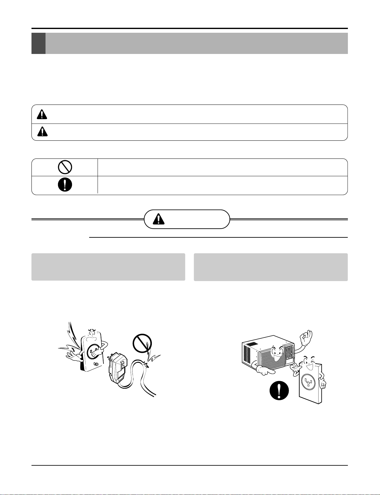
Do not use damaged power cord plugs, or a
loose socket.
• There is risk of fire or electric shock.
Always use the power plug and socket with
the ground terminal.
• There is risk of electric shock.
Be sure not to do.
Be sure to follow the instruction.
Page 4

4 Room Air Conditioner
Safety Precautions
Do not modify or extend the power cord.
• There is risk or fire or electric shock.
Do not install, remove, or re-install the unit by
yourself(customer).
• There is risk of fire, electric shock, explosion, or injury.
Be cautious when unpacking and installing
the product.
• Sharp edges could cause injury. Be especially careful
of the case edges and the fins on the condenser and
evaporator.
Do not store or use flammable gas or combustibles near the air conditioner.
• There is risk of fire or failure of product.
Be sure the installation area does not deteriorate with age.
• If the base collapses, the air conditioner could fall with
it, causing property damage, product failure, and personal injury.
Gasolin
Sharp edges
Page 5

Dimensions
Dimensions
H
W
D
Outside Dimensions
This symbol alerts you to the risk of electric shock.
This symbol alerts you to hazards that could cause harm to the
air conditioner.
This symbol indicates special notes.
NOTICE
Symbols Used in this Manual
Service Manual 5
Model
Dimension
W mm(inch) 471(189/16
H mm(inch) 352(13 7/8) 380(14 31/22)
Dmm(inch)525(20 11/16)576(22 1/16)
REG-71A REG-123A
) 600(23
Heat
5
/8)
Page 6
6 Room Air Conditioner
Specfications
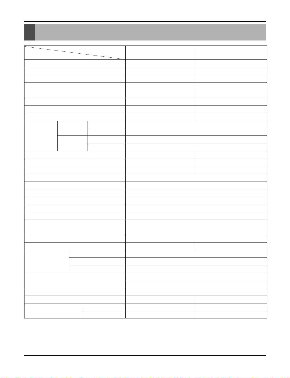
Product Specifications
MODELS
ITEMS
OPERATING
CONDITION
COOLING
HEATING
* DB:Dry Bulb
**
WB:Wet Bulb
NOTE: Please refer to Label Quality on the produst since this specification may be changed for improving performance.
POWER SUPPLY
COOLING CAPACITY (Btu/h)
INPUT (W)
RUNNING CURRENT (A)
E.E.R (BTU/W.h)
HEATING CAPACITY (Btu/h)
INPUT (W)
RUNNING CURRENT (A)
REFRIGERANT (R-22) CHARGE
EVAPORATOR
CONDENSER
FAN, INDOOR
FAN, OUTDOOR
FAN SPEEDS, FAN/COOLING/HEATING
FAN MOTOR
OPERATION CONTROL
ROOM TEMP. CONTROL
AIR DIRECTION CONTROL
CONSTRUCTION
ELECTRIC HEATER
PROTECTOR FAN MOTOR
POWER CORD
DRAIN SYSTEM
NET WEIGHT (lbs/kg)
OUTSIDE DIMENSION (inch)
(W x H x D) (mm)
COMPRESSOR
ELECTRIC HEATER
INDOOR(°C)
OUTDOOR(°C)
INDOOR(°C)
OUTDOOR(°C)
REG-71A REG-123A
1Ø,115V, 60Hz 1Ø, 208/230V, 60Hz
6,900 11,500/12,000
710 1,170/1,220
6.6 5.5/5.8
9.7 9.8/9.8
3850 9,200/11,200
1,260 2,900/3,500
11.0 14.0/15.3
26.7 (DB)* 19.4 (WB)**
35 (DB)* 23.9 (WB)**
21.1 (DB)* 15.6 (DB)**
8.3 (DB)* 6.1 (DB)**
385(13.6 oz) 605(21.3 oz)
2ROW 14STACKS 2ROW 13STACKS
2ROW 16STACKS 2ROW 17STACKS
BLOWER
PROPELLER TYPE FAN WITH SLINGER-RING
1 / 2 / 2
6 POLES
TOUCH PANEL
THERMISTOR
VERTICAL LOUVER(RIGHT&LEFT)
HORIZONTAL LOUVER(UP&DOWN)
SLIDE IN-OUT CHASSIS
1.2KW, 115V 3.5KW, 230V
OVERLOAD PROTECTOR
INTERNAL THERMAL PROTECTOR
FUSE LINK, BIMETAL THERMOSTAT
1.6m(3 WIRE WITH GROUNDING)
ATTACHMENT PLUG(CORD-CONNECTED TYPE)
DRAIN PIPE OR SPLASHED BY FAN SLINGER
60/27 87/39
18 X 13 7/8 X 20 11/16 235/8 X 14 31/22 X 22 5/16
470 X 353 X 525 600 X 380 X 525
Page 7
Service Manual 7
Installation
Installation
Select the Best Location
Installation Check
How to Secure the Drain Pipe(When using drain pipe)
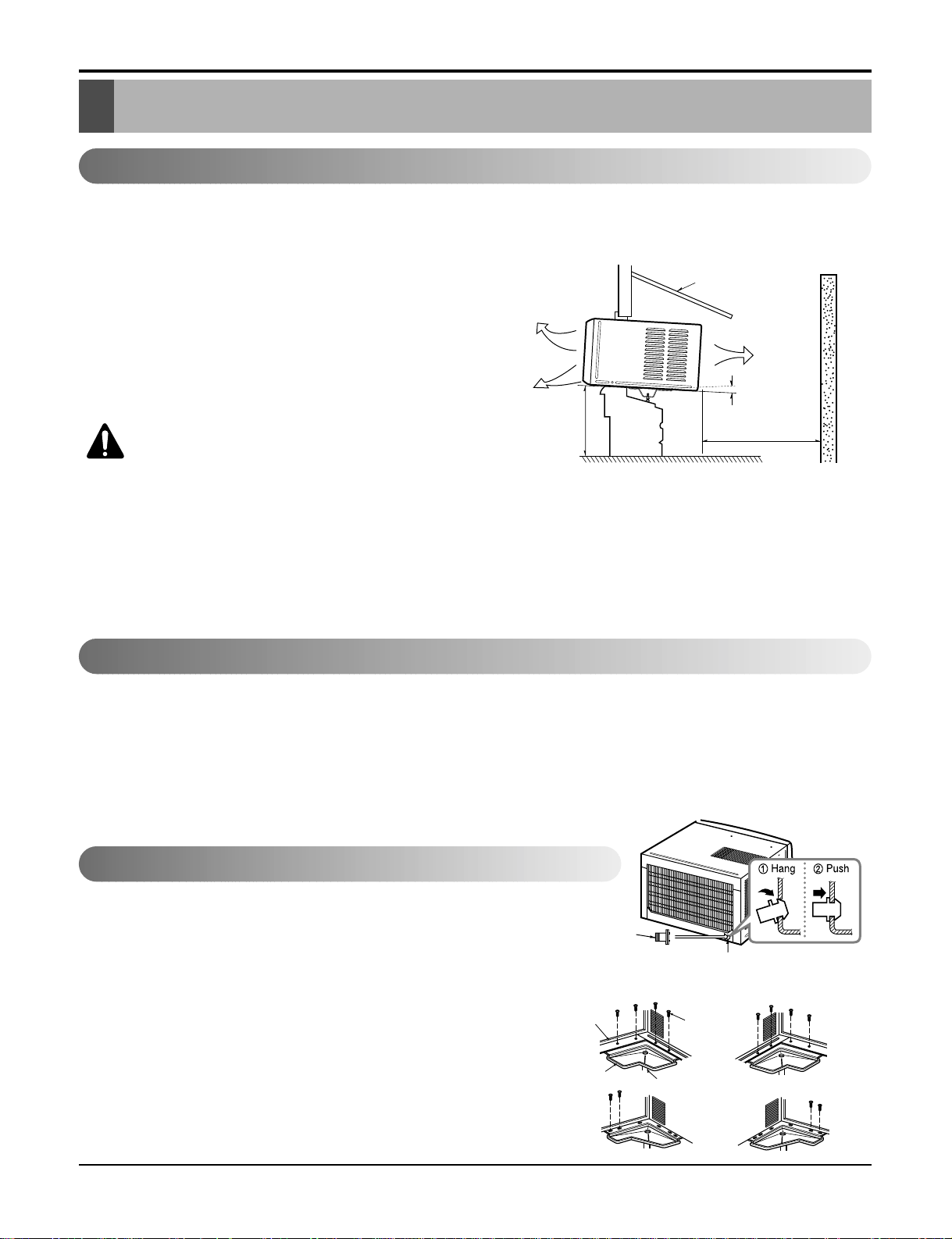
1.To prevent vibration and noise, make sure the unit is
installed securely and firmly.
2.Install the unit where the sunlight does not shine directly
on the unit.
3.The outside of the cabinet must extend outward for at
least 12" and there should be no obstacles, such as a
fence or wall, within 20" from the back of the cabinet
because it will prevent heat radiation of the condenser.
Restriction of outside air will greatly reduce the cooling
efficiency of the air conditioner.
CAUTION: All side louvers of the cabinet
must remain exposed to the outside of
the structure.
4.Install the unit a little slanted so the back is slightly lower
than the front (about 1/2"). This will help force condensed
water to the outside.
5.Install the unit from the bottom about 30"~60" above the
floor level.
The setting conditions must be checked prior to initial starting.
The following items are especially important checking points when the installation is finished.
1. Grounding wire (Green or Green and Yellow) is provided in the power cord. The green wire must be grounded.
2. Connect to a single-outlet 15A circuit.
(or 20A circuit for Electric Heater Model)
3. To avoid vibration or noise, make sure the air conditioner is installed securely.
4 Avoid placing furniture or draperies in front of the air inlet and outlet.
In humid weather, excess water may cause the BASE PAN to overflow. To drain
the water, remove the DRAIN CAP and secure the DRAIN PIPE to the rear hole of
the BASE PAN. Press the drain pipe into the hole by pushing down and away from
the fins to avoid injury.
Optional
1. Install the drain pan over the corner of the cabinet where you removed the
plug with 4 (or 2) screws.
2. Connect the drain hose to the outlet located at the bottom of the drain pan.
You can purchase the drain hose or tubing locally to satisfy your particular
needs. (Drain hose is not supplied).
3. Select the most appropriate connection from among the following figures (by
considering the hole of the unit) to fit drain pan to your own unit.
AWNING
COOLED AIR
HEAT
RADIATION
30"~60"
ABOUT 1/2"
Over 20"
FENCE
Drain pipe
Drain cap
Fig. 4
Fig. 3
Fig. 2
DRAIN
PAN
DRAIN HOSE
Fig. 1
CABINET
SCREW
Figure 1
Page 8
8 Room Air Conditioner
Installation
How to Install(Models without Installation Kit)
1. Remove the screws that fasten the cabinet
at both sides and at the back.
2. Slide the unit from the cabinet by gripping
the base pan handle and pulling forward
while bracing the cabinet.
3. Remove EPS Material.
4. Slide the unit into the cabinet.
CAUTION: For security purpose, reinstall screw at cabinet's sides.
5. Attach the front grille to the cabinet by
inserting the tabs on the grille into the tabs
on the fornt of the cabinet. Push the grille in
until it snaps into place.
6. Lift the inlet grille and secure it with a screw
through the front grille.
Shipping screws
T
IM
E
R
ENERGY
SAVER
M
O
D
E
On/Off
On/Off
Fan Cool
Heat
TIMER
E
N
E
R
G
Y
S
A
V
E
R
MODE
On/Off
On/Off
Fan
Cool
Heat
EPS Material
TIMER
E
N
E
R
G
Y
S
A
V
E
R
MODE
O
n
/O
ff
O
n
/O
ff
F
a
n
C
o
o
l
H
e
a
t
Power cord
Screw
Screw
TIMER
E
N
E
R
G
Y
S
A
V
E
R
MODE
O
n
/O
ff
O
n
/O
f
f
F
a
n
C
o
o
l
H
e
a
t
T
IM
E
R
ENERGY
SAVER
M
O
D
E
O
n
/
O
f
f
O
n
/
O
f
f
F
a
n
C
o
o
l
H
e
a
t
Page 9
Service Manual 9
Installation
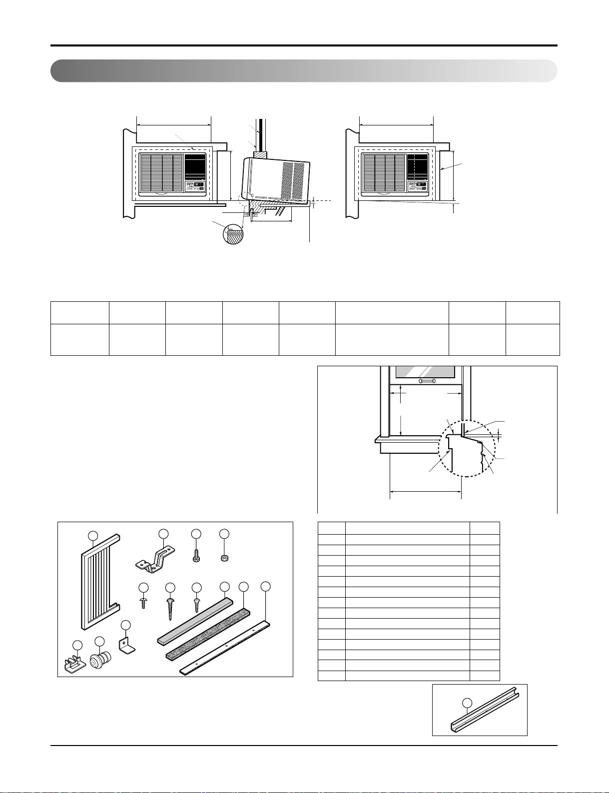
How to Install(Models with Installaion Kit)
When Using Gasket
When Using Installation Kits
1. Window Requirements
This unit is designed for installation in
standard double hung windows with actual opening
widths from 27" to 39".
The top and bottom window sash must open sufficiently to allow a clear vertical opening of 16" from the
bottom of the upper sash to the window stool.
2. Installation Kits Contents
A
B
DE
F
H
2
3
I
4
2
1
A
RIGHT SIDE
HORIZONTAL
LINE
B
1. WINDOW (WIDTH-A, HEIGHT-B)
2. GASKET
3. WALL
4. DETAILS 5.1 x 30 ROUND HEAD WOOD
SCREWS
ABCDE F HI
625mm 392mm 280mm 30mm 0~25mm OVER 420mm 5~10mm -5~5mm
(245/
8") (15
7
/
16") (11
1
/
32") (1
1
/
16") (0~1") (OVER 16
17
/
32") (
3
/
16"~
3
/
8") (-
3
/
16"~
3
/
16")
27" to 39"
16" min
Stool
Interior wall
235
/8" min
(Without frame curtain)
Offset
1
/2" to 11/4"
Sill
Exterior
■ Top retainer bar is in
the product package.
NO. NAME OF PARTS Q'TY
1 FRAME CURTAIN 2
2 SILL SUPPORT 2
3 BOLT 2
4 NUT 2
5
SCREW(TYPE A) (10mm(
2
/
5"))
16
6
SCREW(TYPE B)
3
7
SCREW(TYPE C)
5
8 FOAM-STRIP 1
9
FOAM-PE (920mm x 30mm x 2mm)
1
10
UPPER GUIDE
1
11
FOAM-PE
(600mm x 25mm x 2mm)
1
12 FRAME GUIDE 2
13
WINDOW LOCKING BRACKET
1
14 DRAIN PIPE 1
D5.1mm(0.2")/16mm(0.63")
D4.1mm(0.17")/16mm(0.63")
REG-123A
1
5
13
14
12
2 3 4
76
8 9
11
10
Page 10

Installation
10 Room Air Conditioner
When Using Installation Kits
1. Window Requirements
This unit is designed for installation in
standard double hung windows with actual opening
widths from 22" to 36".
The top and bottom window sash must open sufficiently to allow a clear vertical opening of 15" from
the bottom of the upper sash to the window stool.
REG-71A
A
B
D
E
F
C
HJ
2
3
4
2
1
G
A
RIGHT SIDE
HORIZONTAL
LINE
B
I
TIMER
ENERGY
SAVER
MODE
On/OffOn/Off FanCool
Heat
TIMER
E
N
E
R
G
Y
S
A
V
E
R
MODE
O
n
/
O
f
f
O
n
/
O
f
f
F
a
n
C
o
o
l
H
e
a
t
1. WINDOW (WIDTH-A, HEIGHT-B)
2. GASKET
3. WALL
4. DETAILS 5.1 x 30 ROUND HEAD WOOD
SCREWS
ABCDE F GH J K
495mm 366mm 250mm 30mm 0~25mm OVER 420mm 12mm 32mm 5~10mm 0~5mm
(191/
2") (14
7
/
16") (10") (1
1
/
16") (0~1") (OVER 16
17
/
32") (1/2") (1
1
/
4") (
3
/
16"~
3
/
8") (0~
3
/
16")
2. Installation Kits Contents
22" to 36"
Stool
Interior wall
181/2" min
(Without frame curtain)
Offset
1
/2" to 11/4"
Sill
Exterior
15" min
(With frame curtain)
■ Top retainer bar is in
the product package.
NO. NAME OF PARTS Q'TY
1 FRAME CURTAIN 2
2 SILL SUPPORT 2
3 BOLT 2
4 NUT 2
5
SCREW(TYPE A) (10mm(2/5"))
16
6
SCREW(TYPE B)
3
7
SCREW(TYPE C)
5
8 FOAM-STRIP 1
9
FOAM-PE (920mm x 30mm x 2mm)
1
10
UPPER GUIDE
1
11
FOAM-PE
(600mm x 25mm x 2mm)
1
12 FRAME GUIDE 2
13
WINDOW LOCKING BRACKET
1
14 DRAIN PIPE 1
D5.1mm(0.2")/16mm(0.63")
D4.1mm(0.17")/16mm(0.63")
1
13
14
12
2 3 4
8 9
5
76
11
10
Page 11

Service Manual 11
Suggested Tool Requirements
SCREWDRIVER (+, -), RULER, KNIFE, HAMMER, PENCIL, LEVEL
Installation
Preparation of Chassis
1. Remove the screws that fasten the cabinet at both
sides and at the back.
2. Slide the unit out from the cabinet by gripping the
base pan handle and pulling forward while
bracing the cabinet.
3. Remove EPS Material.
4. Cut the window sash seal to the proper length. Peel
off the backing and attach the foam-pe to the
underside of the window sash.
5. Remove the backing from the top upper guide
Foam PE and attach it to the bottom of the upper
guide .
6. Attach the upper guide onto the top of the cabinet
with 3 type A screws.
7. Insert the frame guides into the bottom of the
cabinet.
8. Insert the Frame Curtain into the upper guide
and frame guides .
9. Fasten the curtains to the unit with 4 Type A screws
at the both sides.
Shipping screws
O
n
/
O
f
f
O
n
/
O
f
f
F
a
n
C
o
o
l
TIM
ER
E
N
H
e
E
a
R
t
G
Y
S
A
V
E
R
M
O
D
E
O
n
/
O
f
f
O
n
/
O
f
f
F
a
n
C
o
o
l
TIM
E
R
E
N
H
e
E
a
R
t
G
Y
S
A
V
E
R
M
O
DE
EPS Material
O
n
/
O
f
f
O
n
/
O
f
f
F
a
n
C
o
o
l
TIM
ER
E
N
H
e
E
a
R
t
G
Y
S
A
V
E
R
M
O
D
E
10
9
11
Cabinet Installation
1. Open the window. Mark a line on center of the window sill(or desired air conditioner location).
Carefully place the cabinet on the window sill and
align the center mark on the bottom front with the
center line marked in the window sill.
2. Pull the bottom window sash down behind the
upper guide until it meets.
NOTICE
Do not pull the window sash down so
tightly that the movement of Frame
Curtain is restricted.
10
5
(Type A)
5
Upper Guide
Window Sash
Cabinet
Frame Curtain
(Type A)
5
12
Window sill
12
Front Angle
Upper guide
1
10
Figure 2
Figure 3
Page 12

12 Room Air Conditioner
INDOOR OUTDOOR
Sill Support
Nut
Bolt
2
4
3
INDOOR OUTDOOR
12
6
7
2
5
Frame Guide
About 1/2"
Screw(Type A)
Cabinet
6
2
About 1/2"
Screw(Type B)5Screw(Type A)
Sill support
Sash track
Front Angle
Type C
Screw(Type B)
Sill support
3. Loosely assemble the sill support using the parts
in Figure 4.
4. Select the position that will place the sill
support near the outer most point on sill
(See Figure 4)
Be careful when you install the cabinet
(Frame Guides are broken easily).
5. Attach the sill support to the cabinet track hole in
relation to the selected position using
2 Type A screws in each support (See Figure 5).
6. The cabinet should be installed with a very slight
tilt (about 1/
2") downward toward the outside
(See Figure 6).
Adjust the bolt and the nut of Sill Support for balancing the cabinet.
7. Attach the cabinet to the window stool by
driving the screws
(Type B) through the front
angle into window stool (5/8").
8. Pull each Frame Curtain properly to each window
sash track, and repeat step 2.
9. Attach each Frame Curtain to the window sash by
using screws (Type C).(See Figure 7)
NOTICE
Figure 4
Figure 5
Figure 6
Figure 7
Installation
Page 13

Service Manual 13
Installation
13
8
Foam-Strip
Screw(Type A)
Screw(Type A)
Power cord
TIMER
E
N
E
R
G
Y
S
A
V
E
R
MODE
O
n
/O
f
f
O
n
/O
ff
Fa
n
C
o
o
l
H
e
a
t
T
I
M
E
R
E
N
E
R
G
Y
S
A
V
E
R
M
O
D
E
On/OffOn/Off
FanCool
Heat
TIMER
ENERGY
SAVER
MODE
On/OffOn/Off FanCool
Heat
10. Slide the unit into the cabinet.(See Fig. 8)
CAUTION:
For security purpose, reinstall
screws (Type A) at the cabinet's sides.
11. Cut the Foam-Strip to the proper length and insert
between the upper and lower window sash.
(See Fig. 9)
12. Attach the window Locking Bracket with a type C
screw. (See Fig. 10)
13. Attach the front grille to the cabinet by inserting the
tabs on the grille into the tabs on the front of the cabinet. Push the grille in until it snaps into place.
(See Fig. 11)
14. Lift the inlet grille and secure it with a type A screw
through the front grille.(See Fig. 12)
Figure 11
Figure 8
Figure 9
Figure 10
Figure 13
Figure 12
Page 14

14 Room Air Conditioner
• Designed for COOLING and HEATING.
• Powerful and whispering cooling.
• Slide-in and slide-out chassis for the simple instal-
lation and service.
• Side air-intake, side cooled-air discharge.
• Built-in adjustable THERMOSTAT
• Washable one-touch filter
• Compact size
• Reliable and efficient rotary compressor
Operation
Operation
Features
Control Locations Function of Controls
CLOSE VENT OPEN
Power
Temp
Fan Speed
Timer Mode
Energy
Saver
1
4
2
7
3
5
Power
Temp
Fan Speed
Timer Mode
Energy
Saver
Auto
Swing
1
4
2
8
7
3
5
REMOTE CONTROLLER
1. POWER BUTTON
To turn the air conditioner ON, push the button. To turn the
air conditioner OFF, push the button again.
This button takes priority over any other buttons.
2. OPERATION MODE SELECTION BUTTON
Everytime you push this button, it will toggle COOL, FAN
and HEAT.
3. ON/OFF TIMER BUTTON
Everytime you push this button, timer is set as
follows.(1Hour ➔ 2Hours ➔ 3Hours ➔ 4Hours ➔ 5Hours
➔ 6Hours ➔ 7Hours ➔ 8Hours ➔ 9Hours ➔ 10Hours ➔
11Hours ➔ 12Hours ➔ Cancel)
4. FAN SPEED SELECTOR
Everytime you push this button, it is set as follows.
(Hi[ ] ➔ Low[ ] ➔ Hi[ ]....)
5. ROOM TEMPERATURE SETTING BUTTON
This button can automatically control the temperature of
the room. The temperature can be set within a range of
60°F to 86°F by 1°F.
6. ENERGY SAVER
The fan stops when the compressor stops cooling.
Approximately every 3 munutes the fan will turn on and
check the room air to determine if cooling is needed.
7. REMOCON SIGNAL RECEIVER
8. AUTO SWING
This button can automatically control the air flow direction.
CAUTION: A slight heat odor may
come from the unit when first
switching to HEAT after the cooling
season is over. This odor, caused by fine
dust particles on the heater, will disappear
quickly.
• VENTILATION
The ventilation lever must be in the CLOSE position in
order to maintain the best cooling conditions.
When a fresh air is necessary in the room, set the ventilation lever to the OPEN position.
The damper is opened and room air is exhausted.
REG-123A
3
2
6
6
4
4
5
5
4
Heat
3
REG-71A
77
3 6 2 5 11
REG-123A REG-71A
Page 15

Service Manual 15
Disassembly
Disassembly
Mechanical Parts
— Before the following disassembly, CONTROL BOX set to OFF and disconnect the power cord.
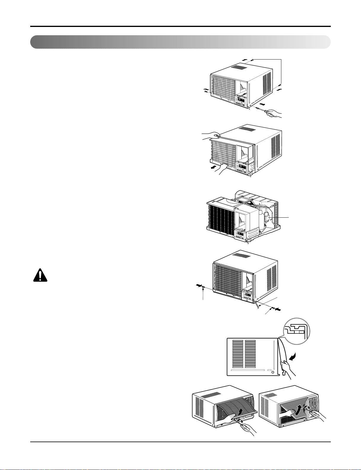
1. Front Grille
1. Open the lnlet grille upward .
2. Remove the screw that fastens the front grille.
3. Pull the front grille from the right side.
4. Remove the front grille.
5. Re-install the component by referring to the removal
procedure, above.(See Figure 14)
2. Cabinet
1. After disassembling the FRONT GRILLE, remove the
2 screws that fasten the cabinet at both sides.
2. Remove the 2 screws that fasten the cabinet at back.
3. Pull the base pan forward. (See Figure 15)
4. Remove the cabinet.
5. Re-install the component by referring to the removal
procedure, above.
3. Control Box
1. Remove the front grille. (Refer to section 1)
2. Remove the cabinet. (Refer to section 2)
3. Remove the 2 screws that fasten the control box
cover.
4. Remove two housings that connect compressor wire
and motor wire in the control box.
5. Discharge the capacitor by placing a 20,000 ohm
resistor across the capacitor terminals.
6. Remove the 2 screws that fasten the control box.
7. Pull the control box forward completely.
8. Re-install the components by referring to the removal
procedure, above. (See Figure 16)
(Refer to the circuit diagram found on page 23 in this
manual and on the control box.)
2
3
4
8
7
6
5
Off
M
e
d
F
a
n
H
ig
h
C
oo
l
TIM
ER
ENERGY
SAVER
M
ODE
On/Off
On/Off
Fan
Cool
Heat
TIM
ER
ENERGY
SAVER
M
O
DE
On/Off
On/Off
Fan
Cool
Heat
Figure 14
Figure 16
Figure 15
Page 16
16 Room Air Conditioner
Disassembly
TIM
ER
ENERG
Y
SAVER
MODE
On/Off
On/Off
Fan
Cool
H
eat
Figure 17
Figure 18
Figure 19
Figure 20
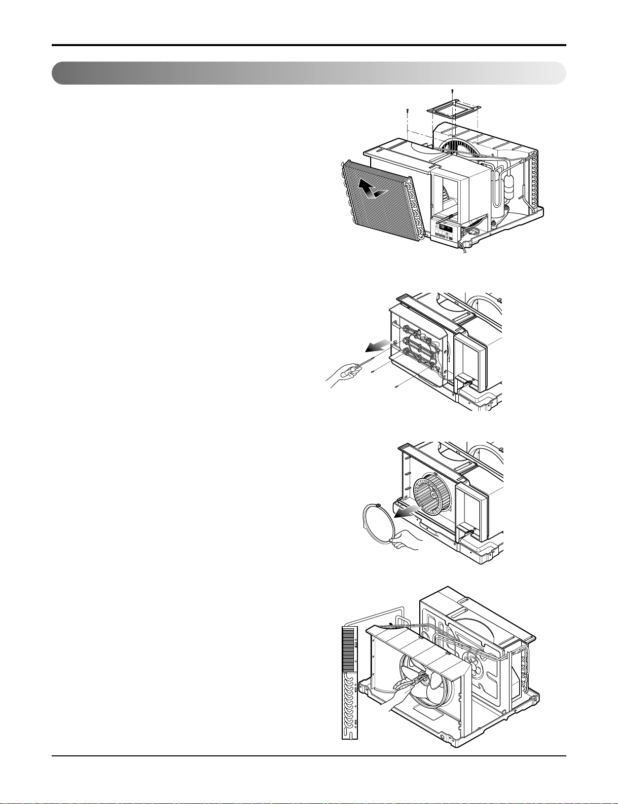
4. Air Guide and Turbo Fan
1. Remove the front grille. (Refer to section 1)
2. Remove the cabinet. (Refer to section 2)
3. Remove the control box. (Refer to section 3)
4. Remove the 4 screws that fasten the brace.
5. Remove the brace.
6. Remove the 2 screws that fasten the evaporator.
7. Move the evaporator forward and pulling it upward
slightly. (See Figure 17)
8. Move the evaporator to the left carefully.
9. Remove the 2 terminals carefully. (See Figure 18,
at Electric heater Model)
10. Remove the 3 screws that fasten the Heater
Cover. (See Figure 18, at Electric Heater Model)
11. Remove the Heater cover. (See Figure 18, at
Electric Heater Model)
12. Pull out the hook of orifice by pushing the tabs
and remove it. (See Figure 19)
13. Remove the clamp with a hand plier that secures
the blower.
14. Remove the blower.
15. Remove the 4 screws that fasten the air guide
from the barrier.
16. Move the air guide backward, pulling out from
the base pan.
17. Re-install the components by referring to the
removal procedure, above.
5. FAN
1. Remove the cabinet. (Refer to section 2)
2. Remove the brace (Refer to section 4)
3. Remove the 4 screws that fasten the condenser.
4. Move the condenser to the left carefully.
5. Remove the clamp that secures the fan.
6. Remove the fan. (See Figure 20)
7. Re-install by referring to the removal procedure.
Air Handling Parts
Page 17

Service Manual 17
6. Shroud
1. Remove the fan. (Refer to section 5)
2. Remove the screw that fastens the shroud.
3. Remove the shroud. (See Figure 21)
4. Re-install the component by referring to the
removal procedure, above.
7. Overload Protector
1. Remove the cabinet. (Refer to section 2)
2. Remove the nut that fastens the terminal cover.
3. Remove the terminal cover. (See Figure 22)
4. Remove all the leads from the overload protector.
5. Remove the overload protector.
6. Re-install the component by referring to the
removal procedure, above.
8. Compressor
1. Remove the cabinet. (Refer to section 2)
2. Discharge the refrigerant system using a
Freon™ Recovery System.
If there is no valve to attach the recovery system, install one (such as a Watco A-1) before
venting the Freon™.. Leave the valve in place
after servicing the system.
3. Remove the overload protector. (Refer to section 7)
4. After purging the unit completely, unbraze the
suction and discharge tubes at the compressor
connections.
5. Remove the 3 nuts and the 3 washers that
fasten the compressor.
6. Remove the compressor. (See Figure 23)
7. Re-install the components by referring to the
removal procedure, above.
Disassembly
Electrical Parts
Figure 21
Figure 22
Figure 23
Page 18

18 Room Air Conditioner
Disassembly
9. Capacitor
1. Remove the control box. (Refer to section 3)
2. Remove the knobs and the screw that fasten
control panel from control box.
3. Remove the screw that located in the front.
4. Open the bottom side of control box.
5. Remove the screw and the clamp that fastens
the capacitor.
6. Disconnect all the leads of capacitor terminals.
7. Re-install the components by referring to the
removal procedure, above. (See Figure 24)
10. Power Cord
1. Remove the control box. (Refer to section 3)
2. Open the control box. (Refer to section 9)
3. Disconnect the grounding screw from the control
box.
4. Disconnect the 2 receptacles.
5. Remove a screw which fastens the clip cord.
(See Figure 25)
6. Remove the power cord.
7. Re-install the component by referring to the
above removal procedure, above.
(Use only one ground-marked hole for ground
connection.)
8. If the supply cord of this appliance is damaged, it
must be replaced by the special cord. (The
special cord means the cord that has the same
specification marked on the supply cord attached
at the unit.)
11. Thermistor
1. Remove the control box. (Refer to section 3)
2. Open the control box. (Refer to section 6)
3. Disconnet the thermistor terminals from main
P.W.B assembly.
4. Remove the thermistor.
5. Re-install the components by refereing to the
above removal procedure. (See Figure 26)
12. SYNCHRONOUS MOTOR
1. Remove the control box. (Refer to section 3)
2. Unfold the control box. (Refer to section 10)
3. Remove the crankshaft.
4. Disconnect all the leads of the synchronous
motor.
5. Remove the 2 screws which fasten the
synchronous motor. (See Fig. 27)
6. Re-install the components by referring to the
removal procedure, above.
Figure 24
Figure 25
Figure 26
Figure 27
Page 19

Service Manual 19
Disassembly
13. Motor
1. Remove the cabinet. (Refer to section 2)
2. Remove the evaporator. (Refer to section 4)
3. Remove the orifice. (Refer to section 4)
4. Remove the blower. (Refer to section 4)
5. Remove the fan. (Refer to section 5)
6. Remove the control box cover and disconnect 5
or 4 wires of motor housing. (Refer to section 3)
7. Remove the 2 or 4 screws that fasten the motor
from the mount motor. (See Figure 28)
8. Remove the motor.
9. Re-install the components by referring to the
removal procedure, above.(See Figure 28)
CAUTION: Discharge the refrigerant
system using a FreonTMRecovery
System. If there is no valve to attach the
recovery system, install one (such as a
WATCO A-1) before venting the FreonTM.
Leave the valve in place after servicing
the system.
14. Condenser
1. Remove the cabinet. (Refer to section 2)
2. Remove the 4 screws that fasten the
brace.(Refer to section 4)
3. Remove the 5 screws that fasten the condenser
and shroud.
4. After discharging the refrigerant completely,
unbraze the interconnecting tube at the condenser connections.
5. Remove the condenser.
6. Re-install the component by referring to notes.
(See Figure 29)
15. Evaporator
1. Remove the cabinet. (Refer to section 2)
2. Remove the 2 screws that fasten the
evaporator.
3. Move the evaporator sideways carefully.
(Refer to section 4)
4. After discharging the refrigerant completely,
unbraze the interconnecting tube at the evaporator connections.
5. Remove the evaporator.
6. Re-install the component by referring to notes.
(See Figure 30)
Figure 28
Figure 29
Figure 30
Refrigerating Cycle
Page 20

20 Room Air Conditioner
Disassembly
16. Capillary Tube
1. Remove the cabinet. (Refer to section 2)
2. After discharging the refrigerant completely,
unbraze the interconnecting tube at the capillary tube.(See caution above)
NOTICE
— Replacement of the refrigeration cycle.
1. When replacing the refrigeration cycle, be sure to
Discharge the refrigerant system using a Freon
recovery System.
If there is no valve to attach the recovery system,
install one (such as a WATCO A-1) before venting
the FreonTM. Leave the valve in place after
servicing the system.
2. After discharging the unit completely, remove the
desired component, and unbraze the pinch-off
tubes.
3. Solder service valves into the pinch-off tube ports,
leaving the valves open.
4. Solder the pinch-off tubes with Service valves.
5. Evacuate as follows.
1) Connect the vacuum pump, as illustrated figure
31A.
2) Start the vacuum pump, slowly open manifold
valves A and B with two full turns counterclockwise and leave the valves open.
The vacuum pump is now pulling through valves
A and B up to valve C by means of the manifold
and entire system.
TM
CAUTION: If high vacuum equip-
ment is used, just crack valves A
and B for a few minutes, then open slowly
with the two full turns counterclockwise.
This will keep oil from foaming and being
drawn into the vacuum pump.
3) Operate the vacuum pump vaccum for 20 to 30
minutes, until 600 microns of vacuum is
obtained. Close valves A and B, and observe
vacuum gauge for a few minutes. A rise in
pressure would indicate a possible leak or
moisture remaining in the system. With valves
A and B closed, stop the vacuum pump.
4) Remove the hose from the vacuum pump and
place it on the charging cylinder. See figure
31B. Open valve C.
Discharge the line at the manifold connection.
5) The system is now ready for final charging.
3. Remove the capillary tube.
4. Re-install the component by referring to notes.
6. Recharge as follows :
1) Refrigeration cycle systems are charged from
the High-side. If the total charge cannot be put
in the High-side, the balance will be put in the
suction line through the access valve which you
installed as the system was opened.
2) Connect the charging cylinder as shown in figure 31B.
With valve C open, discharge the hose at the
manifold connection.
3) Open valve A and allow the proper charge to
enter the system. Valve B is still closed.
4) If more charge is required, the high-side will not
take it. Close valve A.
5) With the unit running, open valve B and add the
balance of the charge.
a. Do not add the liquid refrigerant to the Low-
side.
b. Watch the Low-side gauge; allow pressure to
rise to 30 lbs.
c. Turn off valve B and allow pressure to drop.
d. Repeat steps b. and c. until the balance of the
charge is in the system.
6) When satisfied the unit is operating correctly,
use the pinch-off tool with the unit still running
and clamp on to the pinch-off tube. Using a tube
cutter, cut the pinch-off tube about 2 inches
from the pinch-off tool. Use sil-fos braze and
braze pinch-off tube closed. Turn off the unit,
allow it to set for a while, and then test the leakage of the pinch-off connection.
Page 21

Service Manual 21
Disassembly
A
COMPOUND GAUGE
EVAPORATOR
(LOW PRESSURE SIDE)
COMPRESSOR
CAPILLARY TUBE
CONDENSER
(HIGH PRESSURE SIDE)
SEE INSETS
BELOW
MANIFOLD
GAUGE
B
Figure 31A-Pulling Vacuum
Figure 31B-Charging
A
B
EXTERNAL
VACUUM PUMP
A
CHARGING
CYLINDER
LOW
HI
B
C
Equipment needed: Vacuum pump, Charging cylinder, Manifold gauge, Brazing equipment. Pinch-off tool capable
of making a leak-proof seal, Leak detector, Tubing cutter, Hand Tools to remove components, Service valve.
Page 22

22 Room Air Conditioner
Schematic Diagram
Schematic Diagram
Wiring Diagram
■ ELECTRIC HEATING MODEL
Page 23

Service Manual 23
Troubleshooting Guide
Troubleshooting Guide
Piping System
Figure 32 is a brief description of the important components and their function in what is called the refrigeration
system. This will help you to understand the refrigeration cycle and the flow of the refrigerant in the cooling cycle.
MOTOR
COMPRESSOR
OIL
(LIQUID REFRIGERANT)
CAPILLARY TUBE
OUTSIDE COOLING
AIR FOR REFRIGERANT
PASS THROUGH
SUCTION LINE
COOL LOW PRESSURE VAPOR
COOLED
AIR
COMPLETE LIQUID
BOIL OFF POINT
LIQUID
PRESSURE
DROP
ROOM AIR HEAT LOAD
VAPOR INLET
HOT
DISCHARGED
AIR
LIQUID OUTLET
HIGH PRESSURE VAPOR
LIQUID REFRIGERANT
LOW PRESSURE VAPOR
ROOM AIR CONITIONER
EVAPORATOR COILS CONDENSER COILS
CYCLE OF REFRIGERATION
Figure 32
CONDENSER COIL
FAN
CAPILLARY TUBE
MOTOR
COMPRESSOR
BLOWER
EVAPORATOR COIL
Page 24

24 Room Air Conditioner
Troubleshooting Guide
Troubleshooting Guide
In general, possible trouble is classified in two kinds.
The one is called Starting Failure which is caused from an electrical defect, and the other is ineffective Air
Conditioning caused by a defect in the refrigeration circuit and improper application.
Unit runs but poor cooling.
Ineffective Cooling
Check outdoor coil
(heat exchanger) & the fan
operation.
Check gas leakage.
Repair gas leak.
Replacement of unit if the
unit is beyond repair.
Satisfactory operation with
temperature difference of
inlet & outlet air ;
44~50°F(7~10°C)
Check heat load
increase.
Clean condenser.
Not on separate circuit.
Check inside gas
pressure.
Adjusting of refrigerant
charged.
Malfunction of compressor.
Replacement of
compressor.
Check cold air circulation
for smooth flow.
Dirty indoor coil
(Heat exchanger)
Correct above trouble
Check clogging in refrigeration circuit.
Repair clogging in refrigeration circuit.
Obstruction at air outlet
Clogged of air filter.
Malfunction of fan
Page 25

Service Manual 25
Troubleshooting Guide
Fails to Start
Check circuit breaker
and fuse.
Gas leakage of feeler bulb
of thermostat
Check of control switch.
Fan only fails to start.
Improper wiring.
Defect of fan motor
capacitor.
Irregular motor resistance
(
).
Irregular motor insulation
(
).
Replacement of fan motor.
Regular but fails to start.
Replacement of compressor
(locking of rotor, metal).
Improper thermostat setting.
Loose terminal connection.
Improper wiring.
Irregular motor resistance ( )
Irregular motor insulation ( )
Replacement of compressor
(Motor damaged)
Drop of power voltage.
Capacitor check.
Replacement
Compressor only fails to
start.
Defect of compressor
capacitor.
Check of power source.
Check of control switch
setting.
Page 26

26 Room Air Conditioner
Troubleshooting Guide
COMPLAINT CAUSE REMEDY
Check voltage at outlet. Correct if necessary.
Check voltage to rotary switch. If none, check power
supply cord. Replace cord if circuit is open.
Check switch continuity. Refer to wiring diagram for
terminal identification. Replace switch if defective.
Connect wire. Refer to wiring diagram for terminal
identification. Repair or replace loose terminal.
Test capacitor.
Replace if not within ±10% of manufacturer's rating.
Replace if shorted, open, or damaged.
Fan blade hitting shroud or blower wheel hitting
scroll. Realign assembly.
Units using slinger ring for condenser fan must have
1
/4to 5/16inch clearance to the base. If it hits the
base, shim up the bottom of the fan motor with
mounting screw(s).
Check fan motor bearings; if motor shaft will not
rotate, replace the motor.
Check voltage. If not within limits, call an electrician.
Test capacitor.
Check bearings. Does the fan blade rotate freely?
If not, replace fan motor.
Pay attention to any change from high speed to
low speed. If the speed does not change, replace the
motor.
If cracked, out of balance, or partially missing,
replace it.
If cracked, out of balance, or partially missing,
replace it.
Tighten it.
If knocking sounds continue when running or loose,
replace the motor. If the motor hums or noise
appears to be internal while running, replace motor.
Check voltage.
If not within limits, call an electrician.
Check the wire connections, if loose, repair or
replace the terminal. If wires are off, refer to wiring
diagram for identification, and replace. Check wire
locations. If not per wiring diagram, correct.
Check for continuity, refer to the wiring diagram for
terminal identification. Replace the switch if circuit is
open.
No power
Power supply cord
Rotary switch
Wire disconnected or connection loose
Capacitor (Discharge
capacitor before testing.)
Will not rotate
Revolves on overload.
Fan
Blower
Loose clamper
Worn bearings
Voltage
Wiring
Rotary
Fan motor will not run.
Fan motor runs
intermittently
Fan motor noise.
Compressor will not run,
but fan motor runs.
NAME PLATE RATING MINIMUM MAXIMUM
208~230±10% 187V 253V
115±10% 104V 126V
Room Air Conditioner Voltage Limits
Page 27

Service Manual 27
Troubleshooting Guide
COMPLAINT CAUSE REMEDY
Check the position of knob If not at the coldest setting, advance the knob to this setting and restart
unit.
Check continuity of the thermostat. Replace thermostat if circuit is open.
Check the capacitor.
Replace if not within ±10% of manufacturers rating. Replace if shorted, open, or damaged.
Check the compressor for open circuit or ground. If
open or grounded, replace the compressor.
Check the compressor overload, if externally
mounted. Replace if open. (If the compressor temperature is high, remove the overload, cool it, and
retest.)
Check the voltage.
If not within limits, call an electrician.
Check overload, if externally mounted.
Replace if open. (If the compressor temperature is
high, remove the overload, cool, and retest.)
If not running, determine the cause. Replace if
required.
Remove the cabinet. inspect the interior surface of
the condenser; if restricted, clean carefully with a
vacuum cleaner (do not damage fins) or brush.
Clean the interior base before reassembling.
If condenser fins are closed over a large area on
the coil surface, head pressures will increase,
causing the compressor to overload. Straighten
the fins or replace the coil.
Test capacitor.
Check the terminals. If loose, repair or replace.
Check the system for a restriction.
If restricted, clean of replace.
Close if open.
Determine if the unit is properly sized for the area
to be cooled.
Check the set screw or clamp. If loose or missing,
correct. If the blower or fan is hitting air guide,
rearrange the air handling parts.
Remove the cabinet carefully and rearrange tubing
not to contact cabinet, compressor, shroud, and
barrier.
Set the knob to HIGH COOL or LOW COOL while
rocker switch is ON.
Check terminals. If loose, repair or replace.
Check the synchronous motor for open circuit.
Thermostat
Capacitor (Discharge
capacitor before servicing.)
Compressor
Overload
Voltage
Overload
Fan motor
Condenser air flow restriction
Condenser fins (damaged)
Capacitor
Wiring
Refrigerating system
Air filter
Exhaust damper door
Unit undersized
Blower or fan
Copper tubing
Rotary switch.
Wiring
Synchronous motor.
Compressor will not run,
but fan motor runs.
Compressor cycles on
overload.
Compressor cycles on
overload.
Compressor cycles on
overload.
Insufficient cooling or heating
Excessive noise
Auto air-swing fails.
Page 28

6SHFLILFDWLRQVDQGSHUIRUPDQFHGDWDVXEMHFWWRFKDQJHZLWKRXWQRWLFH
+($7&21752//(5,1&
:(//:257+$9(18(-$&.6210,&+,*$1
7+(48$/,7</($'(5,1&21',7,21,1*$,5
04/18/07
 Loading...