

Page 1
+($7&21752//(5,1&
5RRP$LU&RQGLWLRQHU
REG-183A
REG-243A
6HUYLFH$QG3DUWV0DQXDO
CAUTION
• BEFORE SERVICING THE UNIT, READ THE SAFETY
PRECAUTIONS IN THIS MANUAL.
• ONLY FOR AUTHORIZED SERVICE PERSONNEL
.
Page 2

2 Room Air Conditioner
Air Conditioner Service Manual
TABLE OF CONTENTS
Safety Precautions..........................................................................................................................................3
Dimensions......................................................................................................................................................5
Product Specifications...................................................................................................................................6
Installation .......................................................................................................................................................8
How to Install the Unit ................................................................................................................................8
How to use the Reversible Inlet grille .........................................................................................................8
Window Requirements ...............................................................................................................................9
Installation Kits Contents (some models including installation kit)...........................................................10
Suggested tool Requirements..................................................................................................................10
Cabinet Installation...................................................................................................................................11
Operation .......................................................................................................................................................13
Disassembly instructions.............................................................................................................................14
Mechanical parts......................................................................................................................................14
Air Handling Parts ....................................................................................................................................15
Electrical Parts .........................................................................................................................................16
Refrigeration cycle ...................................................................................................................................19
Schematic Diagram.......................................................................................................................................22
Troubleshooting guide..................................................................................................................................23
Piping System ..........................................................................................................................................23
Troubleshooting guide ..............................................................................................................................24
Room Air Conditioner Voltage Limits........................................................................................................26
Exploded View...............................................................................................................................................28
Replacement Parts List ................................................................................................................................29
Page 3
Service Manual 3
Safety Precautions
Safety Precautions
To prevent injury to the user or other people and property damage, the following instructions must
be followed.
■ Incorrect operation due to ignoring instruction will cause harm or damage. The seriousness is
classified by the following indications.
■ Meanings of symbols used in this manual are as shown below.
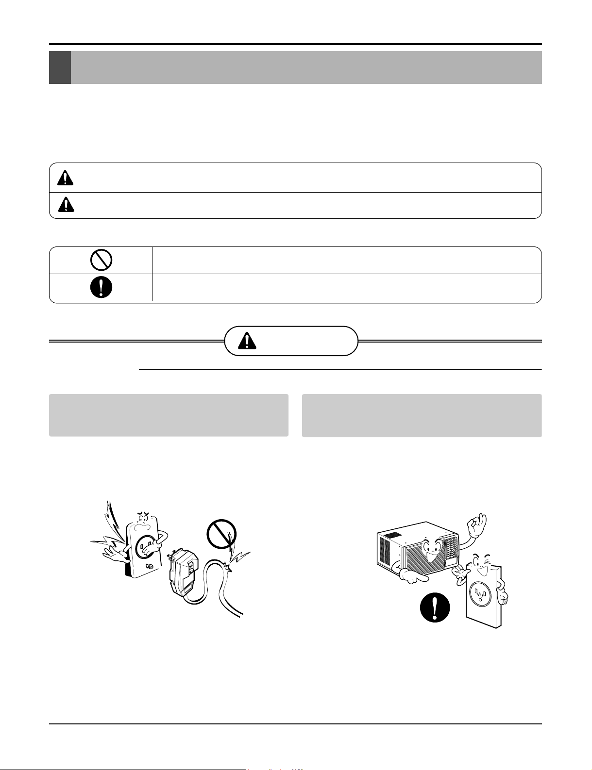
WARNING
CAUTION
This symbol indicates the possibility of death or serious injury.
This symbol indicates the possibility of injury or damage to property only.
WARNING
■ Installation
Do not use damaged power cord plugs, or a
loose socket.
• There is risk of fire or electric shock.
Always use the power plug and socket with
the ground terminal.
• There is risk of electric shock.
Be sure not to do.
Be sure to follow the instruction.
Page 4
4 Room Air Conditioner
Safety Precautions
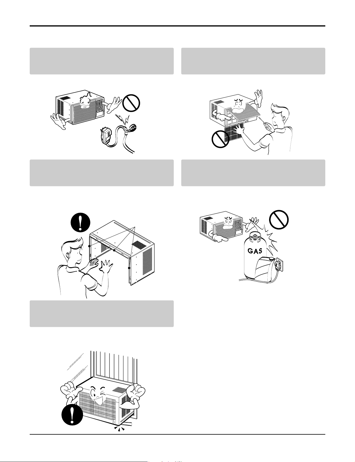
Do not modify or extend the power cord.
• There is risk or fire or electric shock.
Do not install, remove, or re-install the unit by
yourself(customer).
• There is risk of fire, electric shock, explosion, or injury.
Be cautious when unpacking and installing
the product.
• Sharp edges could cause injury. Be especially careful
of the case edges and the fins on the condenser and
evaporator.
Do not store or use flammable gas or combustibles near the air conditioner.
• There is risk of fire or failure of product.
Be sure the installation area does not deteriorate with age.
• If the base collapses, the air conditioner could fall with
it, causing property damage, product failure, and personal injury.
Gasolin
Sharp edges
Page 5
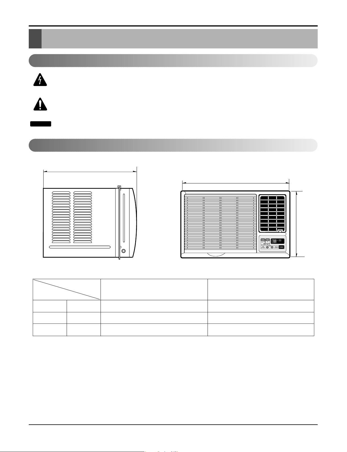
Dimensions
Dimensions
H
W
D
Outside Dimensions
This symbol alerts you to the risk of electric shock.
This symbol alerts you to hazards that could cause harm to the
air conditioner.
This symbol indicates special notes.
NOTICE
Symbols Used in this Manual
Service Manual 5
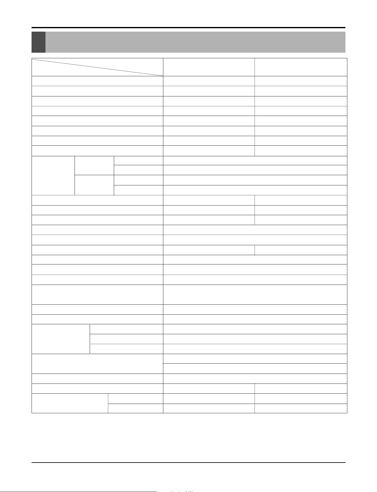
Model
REG-183A REG-243A
Dimension
W mm(inch) 660 (26) 660 (26)
H mm(inch) 428 (16 27/32) 428 (16 27/32)
D mm(inch) 770(30 5/16) 770 (30 5/16)
Page 6
6 Room Air Conditioner
Specfications
Product Specifications
POWER SUPPLY
COOLING CAPACITY (Btu/h)
INPUT (W)
RUNNING CURRENT (A)
E.E.R (BTU/W.h)
HEATING CAPACITY (Btu/h)
INPUT (W)
RUNNING CURRENT (A)
INDOOR(°C)
OUTDOOR(°C)
INDOOR(°C)
OUTDOOR(°C)
REFRIGERANT (R-22) CHARGE
EVAPORATOR
CONDENSER
FAN, INDOOR
FAN, OUTDOOR
FAN SPEEDS, FAN/COOLING/HEATING
FAN MOTOR
OPERATION CONTROL
ROOM TEMP. CONTROL
AIR DIRECTION CONTROL
CONSTRUCTION
ELECTRIC HEATER
COMPRESSOR
PROTECTOR FAN MOTOR
ELECTRIC HEATER
POWER CORD
DRAIN SYSTEM
NET WEIGHT (lbs/kg)
OUTSIDE DIMENSION (inch)
(W x H x D) (mm)
1Ø, 208/230V, 60Hz 1Ø, 208/230V, 60Hz
17,500/17,000 23,00/23,500
1,800/1,750 2,700/2,760
8.2/8.8 13.2/12.2
9.7/9.7 8.5/8.5
11,600/9,400 9,400/11,600
3,100/3,670 3,750/3,770
15.0/16.0 15.0/16.0
26.7 (DB)* 19.4 (WB)**
35 (DB)* 23.9 (WB)**
21.1 (DB)* 15.6 (DB)**
8.3 (DB)* 6.1 (DB)**
810(28.6oz) 1040(36.7oz)
3ROW 18STACKS 3ROW 15STACKS
2ROW 19STACKS,L-BENDING TYPE
2ROW 16STACKS,
L-BENDING TYPE
BLOWER
PROPELLER TYPE FAN WITH SLINGER-RING
1 / 2 / 2 1 / 2 / 2
6 POLES
TOUCH PANEL
THERMISTOR
VERTICAL LOUVER(RIGHT&LEFT)
HORIZONTAL LOUVER(UP&DOWN)
SLIDE IN-OUT CHASSIS
3.5KW, 230V
INTERNAL OVERLOAD PROTECTOR
INTERNAL THERMAL PROTECTOR
FUSE LINK, BIMETAL THERMOSTAT
1.6m(3 WIRE WITH GROUNDING)
ATTACHMENT PLUG(CORD-CONNECTED TYPE)
DRAIN PIPE OR SPLASHED BY FAN SLINGER
137/62 146/66
26 X 16 27/32 X 30 5/16 26 X 16 27/32 X 30 5/16
660 X 428 X 770 660 X 428 X 770
REG-183A REG-243A
MODELS
ITEMS
OPERATING
CONDITION
COOLING
HEATING
* DB:Dry Bulb
**
WB:Wet Bulb
NOTE: Please refer to Label Quality on the produst since this specification may be changed for improving performance.
Page 7
Service Manual 8
Installation
INSTALLATION
How to Install the unit
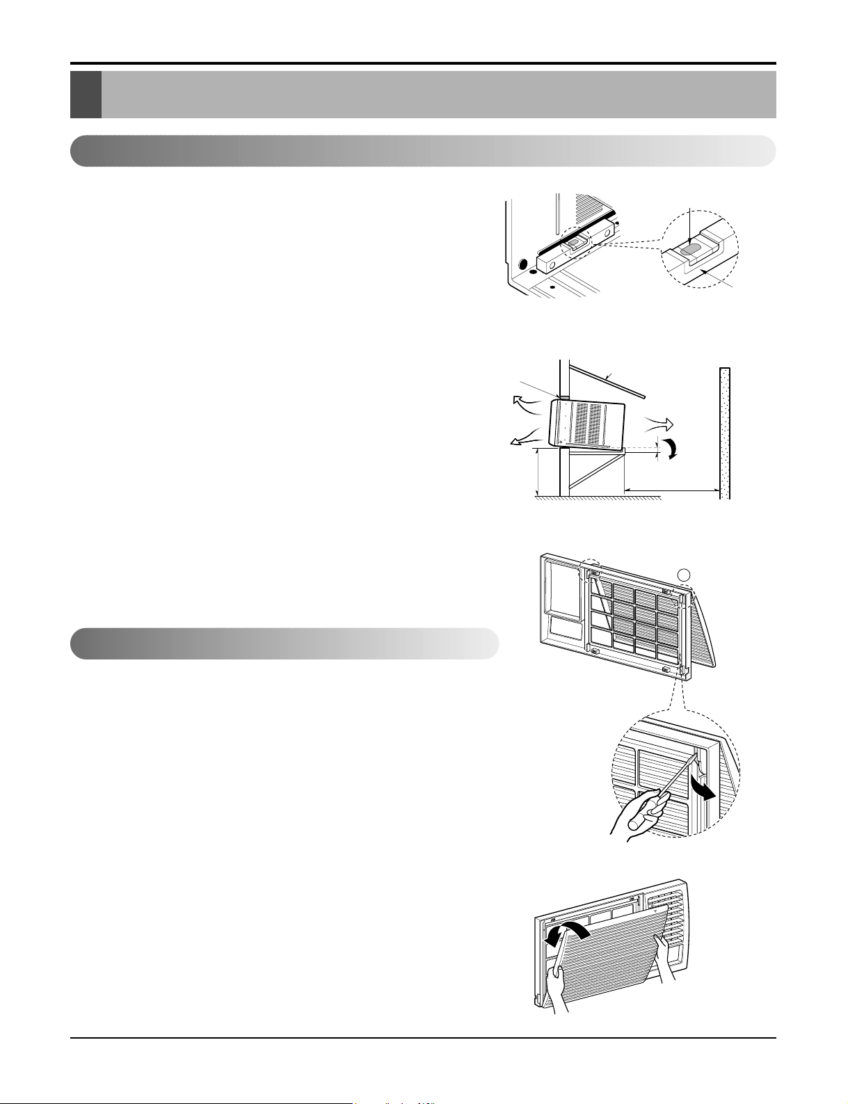
1. To avoid vibration and noise, make sure the unit is
installed securely and firmly.
2. Install the unit where the sunlight does not shine directly
on the unit.
If the unit receives direct sunlight, build an awning to
shade the cabinet.
3. There should be no obstacle, like a fence, within 20"
which might restrict heat radiation from the condenser.
4. To prevent reducing performance, install the unit so that
louvers of the cabinet are not blocked.
5. Install the unit a little obliquely outward not to leak the
condensed water into the room (about 1/2" or 1/4 bubble
with level).
6. Install the unit with its bottom portion 30~60" above the
floor level.
7. Stuff the foam between the top of the unit and the wall to
prevent air and insects from getting into the room.
8. The power cord must be connected to an independent circuit. The green wire must be grounded.
9. Connect the drain tube to the base pan hole in the rear
side if you need to drain (consult a dealer).
Plastic hose or equivalent may be connected to the drain
tube.
The grille is designed to clean the filter both upward and downward.
A. BEFORE ATTACHING THE FRONT GRILLE TO THE CAB-
INET, IF YOU WANT TO PULL OUT THE FILTER
UPWARD;
1. Open the inlet grille slightly (a).
2. Turn inside out the front grille (a).
3. Disassemble the inlet grille from the front grille with separating the
hinged part by inserting a straight type screw-driver tip (b).
4. Then, rotate the inlet grille 180 degrees and insert the hooks into
bottom holes of the front grille.
5. Insert the filter and attach the front grille to the cabinet.
B. IF YOU WANT TO PULL OUT THE FILTER DOWNWARD;
THE GRILLE IS ALREADY DESIGNED FOR THAT WAY.
About 1/2"
Over 20"
HEAT
RADIATION
FENCE
AWNING
FOAM
COOLED
AIR
30-60"
Level
1/4 Bubble
(b)
b
(a)
(c)
How to use the Reversible Inlet grille
Page 8
9 Room Air Conditioner
Installation
Window Requirements
All supporting parts should be secured to firm wood, masonry, or metal.
NOTICE
• WINDOW REQUIREMENTS
1. This unit is designed for installation in standard double hung windows with actual opening widths from 29" to 41".
The top and bottom window sashes must open sufficiently to allow a clear vertical opening of 18" from the bottom of the upper sash to the window stool.
2. The stool offset (height between the stool and sill) must be less than 1 1/4".
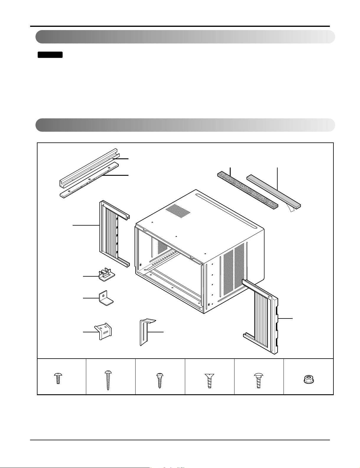
Installation Kits Contents (some models including installation kit)
Foam-PE
(Adhesive-Backed)
Foam-PE
(Adhesive-Backed)
Type C (5) Type D (2)
Type A (14)
Carriage Bolt (2) Lock Nut (4)
Top retainer bar
Type B (7)
Foam strip
(Plain-Back)
Right frame
curtain
Window locking
bracket
Left frame
curtain
Frame guide(2)
Sill
bracket
(2)
Support bracket(2)
Page 9
Service Manual 10
Installation
Suggested tool Requirements
SCREWDRIVER(+, -), RULER, KNIFE, HAMMER, PENCIL, LEVEL
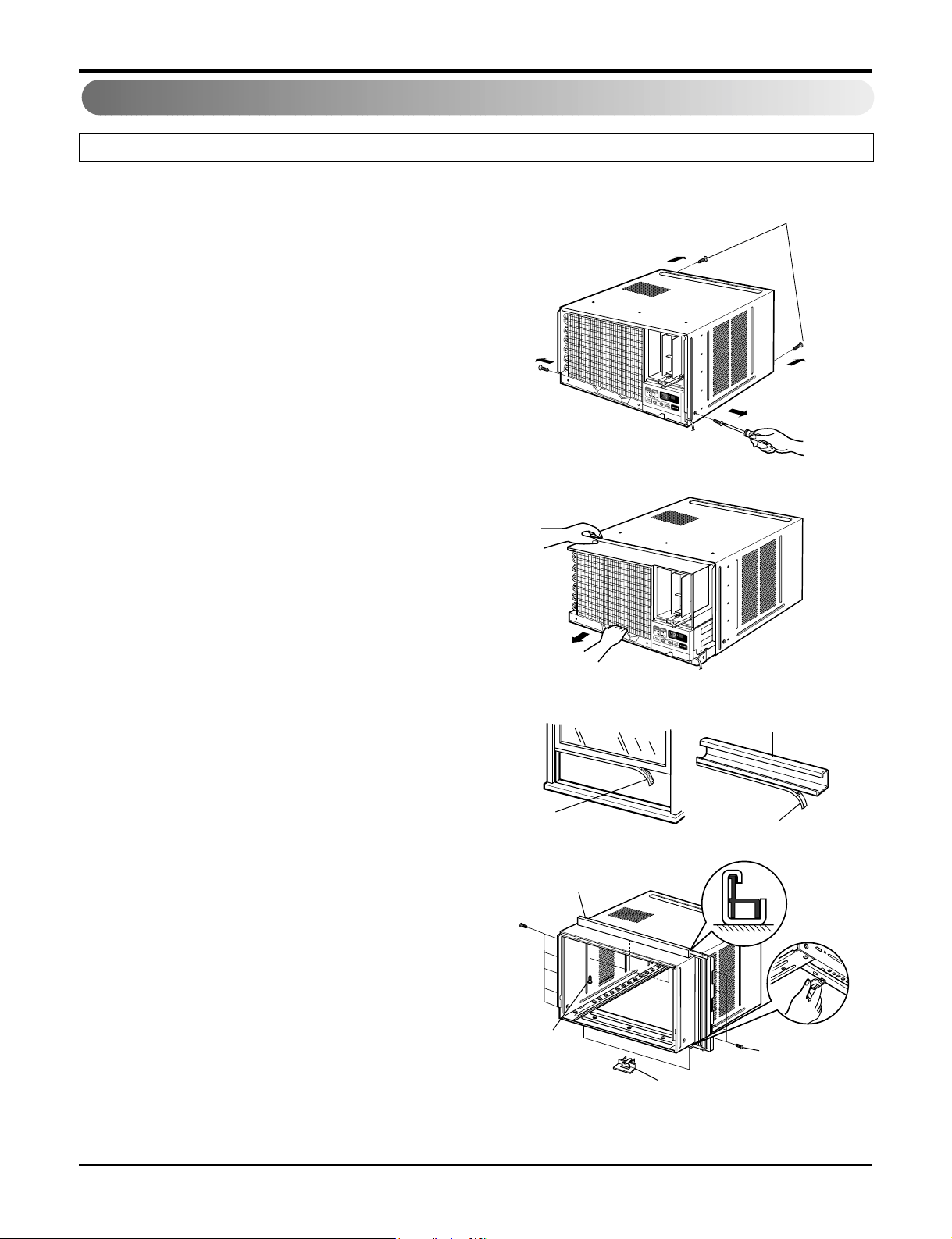
• PREPARATION OF CHASSIS
1. Remove the screws which fasten the cabinet at both sides
and at the back. Keep these two screws which fasten the
cabinet at both sides for later use.
2. Slide the unit out from the cabinet by gripping the base pan
handle and pulling forward while bracing the cabinet.
3. Cut the window sash seal to the proper length. Peel off the
backing and attach the Foam-PE to the underside of the
window sash.
4. Remove the backing from Foam-PE with 3 holes and attach
it to the bottom of the Top retainer bar.
5. Attach the Top retainer bar onto the top of the cabinet with
3 screws (Type A).
6. Insert the Frame guides into the bottom of the cabinet.
7. Insert the Frame Curtain into the Top retainer bar and
Frame guides.
8. Fasten the curtains to the unit with 10 screws (Type A) at
both sides.
Foam-PE
Top retainer bar
Top retainer bar
Foam-PE
Screw
(Type A)
Screw(Type A)
Frame guide
Shipping screws
Figure 1
Figure 2
Figure 3
Figure 4
Page 10

11 Room Air Conditioner
Installation
Cabinet Installation
1. Open the window. Mark a line on the center of the window stool between the side window stop moldings.
Loosely attach the sill bracket to the support bracket
using the carriage bolt and the lock nut.
2. Attach the sill bracket to the window sill using the
screws (Type B).
Carefully place the cabinet on the window stool and
align the center mark on the bottom front with the center
line marked window stool.
3. Using the M-screw and the lock nut, attach the support
bracket to the cabinet track hole. Use the first track hole
after the sill bracket on the outer edge of the window sill.
Tighten the carriage bolt and the lock nut. Be sure the
cabinet slants outward.
CAUTION: Do not drill a hole in the
bottom pan. The unit is designed to
operate with approximately 1/2" of
water in bottom pan.
4. Pull the bottom window sash down behind the Top
retainer bar until they meet.
1. Do not pull the window sash down so tightly that the
movement of Frame curtain is restricted. Attach the
cabinet to the window stool by driving the screws (Type
B) through the cabinet into window stool.
2. The cabinet should be installed with a very slight tilt
downward toward the outside.
NOTICE
Support
Bracket
Lock nut
Sill
Bracket
Carriage
Bolt
(M-Screw)
Cabinet
Track hole
Support
Bracket
Carriage bolt
and lock nut
Machine screw (Type D)
and lock nut
Outer edge
of window
sill
Screw(Type B)
Sill bracket
Front angle
Window stool
Top
retainer
bar
Window sash
Top retainer bar
Cabinet
Foam-PE
Frame curtain
Foam-PE
Screw(Type B)
Front Angle
Sash track
Figure 5
Figure 6
Figure 7
Figure 8
Figure 9
Page 11

Service Manual 12
Installation
5. Pull each Frame curtain fully to each window sash
track, and pull the bottom window sash down behind
the Top retainer bar until it meets.
6. Attach each Frame curtain the window sash by using
screws (Type C). (See Fig. 10)
7. Slide the unit into the cabinet. (See Fig. 11)
CAUTION: For security purpose, reinstall screws (Type A) at cabinet's
sides.
8. Cut the Foam-strip to the proper length and insert
between the upper window sash and the lower window
sash. (See Fig. 12)
9. Attach the Window locking bracket with a screw (Type
C). (See Fig. 13)
10. Attach the front grille to the cabinet by inserting the
tabs on the grille into the tabs on the front of the cabinet. Push the grille in until it snaps into place. (See
Fig.34)
11. Lift the inlet grille and secure it with a screw (Type A)
through the front grille. (See Fig. 14)
12. Window installation of room air conditioner is now
completed.
Power Cord
Screw (Type A)
Screw
Window locking
bracket
Foam-Strip
Screw(Type C)
Figure 10
Figure 11
Figure 12
Figure 13
Figure 14
Figure 15
Page 12

13 Room Air Conditioner
Installation
Operation
Power
Temp
Fan Speed
Timer Mode
Energy
Saver
Auto
Swing
1
4
2
67
3
5
REMOTE CONTROLLER
1. POWER BUTTON
To turn the air conditioner ON, push the button. To turn the air conditioner OFF, push the button again.
This button takes priority over any other buttons.
2. OPERATION MODE SELECTION BUTTON
Everytime you push this button, it will toggle COOL, FAN and HEAT.
3. ON/OFF TIMER BUTTON
Everytime you push this button, timer is set as follows.(1Hour ➔ 2Hours ➔ 3Hours ➔ 4Hours ➔ 5Hours ➔ 6Hours ➔
7Hours ➔ 8Hours ➔ 9Hours ➔ 10Hours ➔ 11Hours ➔ 12Hours ➔ Cancel)
4. FAN SPEED SELECTOR
Everytime you push this button, it is set as follows. (Hi[ ] ➔ Low[ ] ➔ Hi[ ]....)
5. ROOM TEMPERATURE SETTING BUTTON
This button can automatically control the temperature of the room. The temperature can be set within a range of 60°F to
86°F by 1°F.
6. AUTO SWING
This button can automatically control the air flow direction.
7. ENERGY SAVER
The fan stops when the compressor stops cooling.
Approximately every 3 munutes the fan will turn on and check the room air to determine if cooling is needed.
8. REMOCON SIGNAL RECEIVER
CAUTION: A slight heat odor may come from the unit when first switching to
HEAT after the cooling season is over. This odor, caused by fine dust particles on
the heater, will disappear quickly.
• VENTILATION
The ventilation lever must be in the CLOSE position in
order to maintain the best cooling conditions.
When a fresh air is necessary in the room, set the ventilation lever to the OPEN position.
The damper is opened and room air is exhausted.
CLOSE VENT OPEN
Page 13

Service Manual 14
Disassembly
Disassembly
- Before the following disassembly, power switch is set to off and disconnected the power cord.
Mechanical parts
1. Front grille
1. Open the inlet grille upward or downward.
2. Remove the screw which fastens the front grille.
3. Pull the front grille from the right side.
4. Remove the front grille. (See Fig. 16)
5. Re-install the component by referring to the
removal procedure.
Mark ∆ of inlet grille means opening direction.
NOTICE
Figure 16
Figure 17
Figure 18
2. Cabinet
1. After disassembling the front grille, remove the screws
which fasten the cabinet at both sides. Keep these for
later use.
2. Remove the two screws which fasten the cabinet at
back. (See Fig. 17)
3. Pull the base pan forward.
3. Control box
1. Remove the front grille. (Refer to section 1)
2. Pull the base pan forward so that you can remove the
2 screws which fasten the cover control at the right
side. (See Fig. 18)
3. Remove the 3 screws which fasten the controlbox.
(See Fig. 18)
4. Discharge the capacitor by placing a 20,000 ohm
resistor across the capacitor terminals.
5. Disconnect two wire housings in the control box.
6. Pull the control box forward completely.
7. Re-install the components by referring to the removal
procedure. (See Fig. 18)
(Refer to the wiring diagram found on page 29~30 in this
manual and on the control box.)
Page 14

15 Room Air Conditioner
Disassembly
Air handling parts
4. Cover (at the top)
1. Remove the front grille. (Refer to section 1)
2. Remove the cabinet. (Refer to section 2)
3. Remove 11 screws which fasten the brace and covers.
4. Remove the covers and the brace. (See Fig. 19)
5. Re-install the components by referring to the removal
procedure, above.
5. Blower
1. Remove the cover. (Refer to section 4)
2. Remove the 3 screws which fasten the evaporator at the
left side and the top side.(See Fig. 19)
3. Move the evaporator sideward carefully.
4. Remove the 2 terminals carefully(See Fig. 20).
5. Remove the 3 screws which fasten the Heater Cover.
(See Fig. 20)
6. Remove the Heater Cover.(See Fig. 20)
7. Remove the orifice from the air guide carefully. (See Fig. 21)
8. Remove the clamp which secures the blower with plier.
(See Fig. 21)
9. Remove the blower with plier or your hand without
touching blades. (See Fig. 22)
10. Re-install the components by referring to the removal
procedure, above.
Figure 19
Figure 20
Figure 21
Figure 22
Page 15

Service Manual 16
Disassembly
6. Fan
1. Remove the cabinet. (Refer to section 2)
2. Remove the brace and shroud cover.
(Refer to section 4)
3. Remove the side cover with 2 screws.(See Fig. 23)
4. Remove the 5 or 6 screws which fasten the condenser.
5. Move the condenser sideways carefully.
6. Remove the clamp which secures the fan.
7. Remove the fan. (See Fig. 23)
8. Re-install the components by referring to the removal
procedure, above.
7. Shroud
1. Remove the fan. (Refer to section 6)
2. Remove the 2 screws which fasten the shroud.
3. Remove the shroud. (See Fig. 24)
4. Re-install the component by referring to the removal
procedure, above.
8. Motor
1. Remove the cabinet. (Refer to section 2)
2. Remove the cover control and disconnect a wire housing in control box. (Refer to section 3)
3. Remove the blower. (Refer to section 5)
4. Remove the fan. (Refer to section 6)
5. Remove the 4 screws which fasten the motor. (See Fig.
25)
6. Remove the motor.
7. Re-install the components by referring to the removal
procedure, above.
9. Compressor
1. Remove the cabinet. (Refer to section 2)
2. Discharge the refrigerant system using FreonTM
Recovery System.
If there is no valve to attach the recovery system,
install one (such as a watco a-1) before venting the
FreonTM. Leave the valve in place after servicing the
system.
3. Disconnect the 3 leads from the compressor.
4. After purging the unit completely, unbraze the suction
and discharge tubes at the compressor connections.
5. Remove the 3 nuts and the 3 washers which fasten the
compressor. (See Fig. 26)
6. Remove the compressor.
7. Re-instill the components by referring to the removal
procedure, above.
Electrical parts
Figure 23
Figure 24
Figure 25
Figure 26
Page 16

17 Room Air Conditioner
Disassembly
10. CAPACITOR
1. Remove the control box. (Refer to section 3)
2. Remove the screw and knobs which fasten the display
panel.
3. Disconnect the 2 leads from the rocker switch and
remove the panel.
4. Remove a screw and unfold the control box.
(See Fig. 27)
5. Remove the screw and the clamp which fastens the
capacitor. (See Fig. 27)
6. Disconnect all the leads of capacitor terminals.
7. Re-install the components by referring to the removal
procedure, above.
11. POWER CORD
1. Remove the control box. (Refer to section 3)
2. Unfold the control box. (Refer to section 10)
3. Disconnect the grounding screw from the control box.
4. Disconnect 2 receptacles.
5. Remove a screw which fastens the clip cord.
6. Pull the power cord. (See Fig. 28)
7. Re-install the component by referring to the removal
procedure, above.
(Use only one ground-marked hole for ground connection.)
8. If the supply cord of this appliance is damaged, it must
be replaced by the special cord.
(The special cord means the cord which has the
same specification marked on the supply cord fitted
to the unit.)
12. THERMISTOR
1. Remove the control box. (Refer to section 3)
2. Unfold the control box. (Refer to section 10)
3. Disconnect the thermistor terminals from main P.W.B
assembly.
4. Remove the thermistor.
5. Re-install the components by referring to the removal
procedure above. (See Figure 30)
Figure 28
Figure 27
Figure 29
Page 17

Service Manual 18
Disassembly
13. SYNCHRONOUS MOTOR
1. Remove the control box. (Refer to section 3)
2. Unfold the control box. (Refer to section 10)
3. Remove the crankshaft.
4. Disconnect all the leads of the synchronous motor.
5. Remove the 2 screws which fasten the synchronous
motor. (See Fig. 30)
6. Re-install the components by referring to the removal
procedure, above.
Figure 30
Page 18

19 Room Air Conditioner
Disassembly
Refrigeration cycle
CAUTION: Discharge the refrigerant system using FreonTMRecovery System.If
there is no valve to attach the recovery system, install one (such as a WATCO A-1)
before venting the FreonTM. Leave the valve in place after servicing the system.
16. CONDENSER
1. Remove the cabinet. (Refer to section 2)
2. Remove the brace and the shroud cover.
(Refer to section 4)
3.
Remove 2 screws which fasten the side cover.(See Fig.
31)
4. Remove the 5 or 6 screws which fasten the condenser.
5. After discharging the refrigerant completely, unbraze
the interconnecting tube at the condenser connections.
6. Remove the condenser.
7. Re-install the components by referring to notes.
(See Fig. 31)
17. EVAPORATOR
1. Remove the cabinet. (Refer to section 2)
2. Remove the top cover and the brace.
(Refer to section 4)
3. Discharge the refrigerant completely.
4. Remove the 3 screws which fasten the evaporator at
the left side and the top side.
5. Move the evaporator sideward carefully and then
unbraze the interconnecting tube at the evaporator
connectors.
6. Remove the evaporator.
7. Re-install the components by referring to notes.
(See Fig. 32)
18. CAPILLARY TUBE
1. Remove the cabinet. (Refer to section 2)
2. Remove the brace. (Refer to section 4)
3. After discharging the refrigerant completely, unbraze
the interconnecting tube at the capillary tube.
4. Remove the capillary tube.
5. Re-install the components by referring to notes.
Figure 31
Figure 32
Page 19

Service Manual 20
- Replacement of the refrigeration cycle.
1. When replacing the refrigeration cycle, be sure to
discharge the refrigerant system using a Freon
TM
recovery System.
If there is no valve to attach the recovery system,
install one (such as a WATCO A-1) before venting
the FreonTM. Leave the valve in place after
servicing the system.
2. After discharging the unit completely, remove the
desired component, and unbrace the pinch-off tubes.
3. Solder service valves into the pinch-off tube ports,
leaving the valves open.
4. Solder the pinch-off tubes with Service valves.
5. Evacuate as follows.
1) Connect the vacuum pump, as illustrated Fig. 35A.
2) Start the vacuum pump, slowly open manifold
valves A and B with two full turns counterclockwise and leave the valves closed.
The vacuum pump is now pulling through valves A
and B up to valve C by means of themanifold
and entire system.
3) Operate the vacuum pump for 20 to 30 minutes,
until 600 microns of vacuum is obtained. Close
valves A and B, and observe vacuum gauge for
a few minutes. A rise in pressure would indicate a
possible leak or moisture remaining in the system. With valves A and B closed, stop the vacuum pump.
4) Remove the hose from the vacuum pump and
place it on the charging cylinder. See Fig. 35B.
Open valve C.
Discharge the line at the manifold connection.
5) The system is now ready for final charging.
6. Recharge as follows :
1) Refrigeration cycle systems are charged from the
High-side. If the total charge cannot be put in the
High-side, the balance will be put in the suction
line through the access valve which you installed
as the system was opened.
2) Connect the charging cylinder as shown in Fig.
35B.
With valve C open, discharge the hose at the
manifold connection.
3) Open valve A and allow the proper charge to
enter the system. Valve B is still closed.
4) If more charge is required, the high-side will not
take it. Close valve A.
5) With the unit running, open valve B and add the
balance of the charge.
a. Do not add the liquid refrigerant to the Low-
side.
b. Watch the Low-side gauge; allow pressure to
rise to 30 lbs.
c. Turn off valve B and allow pressure to drop.
d. Repeat steps B and C until the balance of the
charge is in the system.
6) When satisfied the unit is operating correctly, use
the pinch-off tool with the unit still running and
clamp on to the pinch-off tube. Using a tube cutter, cut the pinch-off tube about 2 inches from the
pinch-off tool. Use sil-fos solder and solder pinchoff tube closed. Turn off the unit, allow it to set for
a while, and then test the leakage of the pinch-off
connection.
NOTICE
CAUTION: If high vacuum equipment is used, just crack valves A
and B for a few minutes, then
open slowly with the two full turns counterclockwise. This will keep oil from
foaming and being drawn into the vacuum pump.
Page 20

21 Room Air Conditioner
Disassembly
Equipment needed: Vacuum pump, Charging cylinder, Manifold gauge, Brazing equipment. Pin-off tool capable
of making a leak-proof seal, Leak detector, Tubing cutter, Hand Tools to remove components, Service valve.
A
COMPOUND GAUGE
EVAPORATOR
(LOW PRESSURE SIDE)
COMPRESSOR
CAPILLARY TUBE
CONDENSER
(HIGH PRESSURE SIDE)
SEE INSETS
BELOW
MANIFOLD
GAUGE
B
Figure 31A-Pulling Vacuum
Figure 31B-Charging
A
B
EXTERNAL
VACUUM PUMP
A
CHARGING
CYLINDER
LOW
HI
B
C
Page 21

Service Manual 22
Schematic Diagram
Schematic Diagram
Wiring Diagram
■ ELECTRIC HEATING MODEL
Page 22

23 Room Air Conditioner
Troubleshooting Guide
Troubleshooting Guide
Piping System
Figure 32 is a brief description of the important components and their function in what is called the refrigeration
system. This will help you to understand the refrigeration cycle and the flow of the refrigerant in the cooling cycle.
MOTOR
COMPRESSOR
OIL
(LIQUID REFRIGERANT)
CAPILLARY TUBE
OUTSIDE COOLING
AIR FOR REFRIGERANT
PASS THROUGH
SUCTION LINE
COOL LOW PRESSURE VAPOR
COOLED
AIR
COMPLETE LIQUID
BOIL OFF POINT
LIQUID
PRESSURE
DROP
ROOM AIR HEAT LOAD
VAPOR INLET
HOT
DISCHARGED
AIR
LIQUID OUTLET
HIGH PRESSURE VAPOR
LIQUID REFRIGERANT
LOW PRESSURE VAPOR
ROOM AIR CONITIONER
EVAPORATOR COILS CONDENSER COILS
CYCLE OF REFRIGERATION
Figure 32
CONDENSER COIL
FAN
CAPILLARY TUBE
MOTOR
COMPRESSOR
BLOWER
EVAPORATOR COIL
Page 23

Service Manual 24
Troubleshooting Guide
Troubleshooting Guide
In general, possible trouble is classified in two kinds.
The one is called Starting Failure which is caused from an electrical defect, and the other is ineffective Air
Conditioning caused by a defect in the refrigeration circuit and improper application.
Unit runs but poor cooling.
Ineffective Cooling
Check outdoor coil
(heat exchanger) & the fan
operation.
Check gas leakage.
Repair gas leak.
Replacement of unit if the
unit is beyond repair.
Satisfactory operation with
temperature difference of
inlet & outlet air ;
44~50°F(7~10°C)
Check heat load
increase.
Clean condenser.
Not on separate circuit.
Check inside gas
pressure.
Adjusting of refrigerant
charged.
Malfunction of compressor.
Replacement of
compressor.
Check cold air circulation
for smooth flow.
Dirty indoor coil
(Heat exchanger)
Correct above trouble
Check clogging in refrigeration circuit.
Repair clogging in refrigeration circuit.
Obstruction at air outlet
Clogged of air filter.
Malfunction of fan
Page 24

25 Room Air Conditioner
Troubleshooting Guide
Fails to Start
Check circuit breaker
and fuse.
Gas leakage of feeler bulb
of thermostat
Check of control switch.
Fan only fails to start.
Improper wiring.
Defect of fan motor
capacitor.
Irregular motor resistance
(
).
Irregular motor insulation
(
).
Replacement of fan motor.
Regular but fails to start.
Replacement of compressor
(locking of rotor, metal).
Improper thermostat setting.
Loose terminal connection.
Improper wiring.
Irregular motor resistance ( )
Irregular motor insulation ( )
Replacement of compressor
(Motor damaged)
Drop of power voltage.
Capacitor check.
Replacement
Compressor only fails to
start.
Defect of compressor
capacitor.
Check of power source.
Check of control switch
setting.
Page 25

Service Manual 26
Troubleshooting Guide
COMPLAINT CAUSE REMEDY
Check voltage at outlet. Correct if necessary.
Check voltage to rotary switch. If none, check power
supply cord. Replace cord if circuit is open.
Check switch continuity. Refer to wiring diagram for
terminal identification. Replace switch if defective.
Connect wire. Refer to wiring diagram for terminal
identification. Repair or replace loose terminal.
Test capacitor.
Replace if not within ±10% of manufacturer's rating.
Replace if shorted, open, or damaged.
Fan blade hitting shroud or blower wheel hitting
scroll. Realign assembly.
Units using slinger ring for condenser fan must have
1
/4to 5/16inch clearance to the base. If it hits the
base, shim up the bottom of the fan motor with
mounting screw(s).
Check fan motor bearings; if motor shaft will not
rotate, replace the motor.
Check voltage. If not within limits, call an electrician.
Test capacitor.
Check bearings. Does the fan blade rotate freely?
If not, replace fan motor.
Pay attention to any change from high speed to
low speed. If the speed does not change, replace the
motor.
If cracked, out of balance, or partially missing,
replace it.
If cracked, out of balance, or partially missing,
replace it.
Tighten it.
If knocking sounds continue when running or loose,
replace the motor. If the motor hums or noise
appears to be internal while running, replace motor.
Check voltage.
If not within limits, call an electrician.
Check the wire connections, if loose, repair or
replace the terminal. If wires are off, refer to wiring
diagram for identification, and replace. Check wire
locations. If not per wiring diagram, correct.
Check for continuity, refer to the wiring diagram for
terminal identification. Replace the switch if circuit is
open.
No power
Power supply cord
Rotary switch
Wire disconnected or connection loose
Capacitor (Discharge
capacitor before testing.)
Will not rotate
Revolves on overload.
Fan
Blower
Loose clamper
Worn bearings
Voltage
Wiring
Rotary
Fan motor will not run.
Fan motor runs
intermittently
Fan motor noise.
Compressor will not run,
but fan motor runs.
NAME PLATE RATING MINIMUM MAXIMUM
208~230±10% 187V 253V
115±10% 104V 126V
Room Air Conditioner Voltage Limits
Page 26

27 Room Air Conditioner
Troubleshooting Guide
COMPLAINT CAUSE REMEDY
Check the position of knob If not at the coldest setting, advance the knob to this setting and restart
unit.
Check continuity of the thermostat. Replace thermostat if circuit is open.
Check the capacitor.
Replace if not within ±10% of manufacturers rating. Replace if shorted, open, or damaged.
Check the compressor for open circuit or ground. If
open or grounded, replace the compressor.
Check the compressor overload, if externally
mounted. Replace if open. (If the compressor temperature is high, remove the overload, cool it, and
retest.)
Check the voltage.
If not within limits, call an electrician.
Check overload, if externally mounted.
Replace if open. (If the compressor temperature is
high, remove the overload, cool, and retest.)
If not running, determine the cause. Replace if
required.
Remove the cabinet. inspect the interior surface of
the condenser; if restricted, clean carefully with a
vacuum cleaner (do not damage fins) or brush.
Clean the interior base before reassembling.
If condenser fins are closed over a large area on
the coil surface, head pressures will increase,
causing the compressor to overload. Straighten
the fins or replace the coil.
Test capacitor.
Check the terminals. If loose, repair or replace.
Check the system for a restriction.
If restricted, clean of replace.
Close if open.
Determine if the unit is properly sized for the area
to be cooled.
Check the set screw or clamp. If loose or missing,
correct. If the blower or fan is hitting air guide,
rearrange the air handling parts.
Remove the cabinet carefully and rearrange tubing
not to contact cabinet, compressor, shroud, and
barrier.
Set the knob to HIGH COOL or LOW COOL while
rocker switch is ON.
Check terminals. If loose, repair or replace.
Check the synchronous motor for open circuit.
Thermostat
Capacitor (Discharge
capacitor before servicing.)
Compressor
Overload
Voltage
Overload
Fan motor
Condenser air flow restriction
Condenser fins (damaged)
Capacitor
Wiring
Refrigerating system
Air filter
Exhaust damper door
Unit undersized
Blower or fan
Copper tubing
Rotary switch.
Wiring
Synchronous motor.
Compressor will not run,
but fan motor runs.
Compressor cycles on
overload.
Compressor cycles on
overload.
Compressor cycles on
overload.
Insufficient cooling or heating
Excessive noise
Auto air-swing fails.
Page 27

Service Manual 28
Exploded View
Exploded View
159830
135314
147581-1
147581-2
135312
552102
753010
554031
148000
749750
349600
346811
130410
354210
147582
349001
359012
749740
W48602
W48602
559011
149980
550140
554160
352115-1
352113
35211A
352111
567480
268711-1
146812
264110
267110
137215
238310
W0CZZ
249950
135510
130910
753000
135500
731273
135515
268711-2
352115-2
Page 28

REG-183A
DESCRIPTION
130410 3041A23004F Base Assy Single R
130910 3091AR6056Q Cabinet Assy Single R
135312 AEB30969402 Grille Assy Front R
135314 3530AR1604A Grille Assy Inlet R
135510 3551A30015A COVER ASSEMBLY, CONTROL R
137215 3720AR6163A PANEL, CONTROL R
146812 2H01102J MOTOR ASSEMBLY, SYNC R
147581-1 4758AR7264C Louver ,HORIZONTAL R
147581-2 4758AR7278C LOUVER, HORIZONTAL R
147582 4758AR6157B LOUVER, VERTICAL R
148000 4800AR7271A BRACE R
149980 4998AR1597B SHROUD R
159830 5231AR6159A FILTER(MECH), A/C R
238310 MDD37823802 ESCUTCHEON R
249950 4995A20186K CONTROL BOX ASSEMBLY, SINGLE R
264110 6411A20056Q POWER CORD ASSEMBLY R
567480 6323A20003S THERMISTOR ASSEMBLY R
268711-1 6871A20611V PWB(PCB) ASSEMBLY, DISPLAY R
268711-2 EBR30851603 PWB(PCB) ASSEMBLY, MAIN(AC) R
267110 6711A20035A REMOTE CONTROLLER R
346811 4681A20081T MOTOR ASSEMBLY, AC R
349001 4900AR7265A DAMPER, VENTILATION R
349600 4960AR1596A MOUNT, MOTOR R
352111 5211AR7059A TUBE ASSEMBLY, CONNECTOR R
352113 5211A25040C TUBE ASSEMBLY, DISCHARGE SINGLE R
35211A 5211A20204G TUBE ASSEMBLY, SUCTION SINGLE R
749750 5239A20001N AIR GUIDE ASSEMBLY R
354210 5421A20059F EVAPORATOR ASSEMBLY, FIRST R
359012 5834AR1599B FAN ASSEMBLY, BLOWER R
550140 4H00982C ISOLATOR, COMP R
552102 5210A24956Q Tube,Bending R
554031 5403A20062F CONDENSER ASSEMBLY, BENDING R
554160 2520UCBJ002 COMPRESSOR R
559011 5900AR1508B FAN ASSEMBLY, AXIAL R
753000 5300A20003A HEATER, ELECTRIC R
753010 5301A30001B HEATER ASSEMBLY, ELECTRIC R
W0CZZ 6120AR2194F CAPACITOR, DRAWING R
W48602 3H02932C CLAMP, SPRING R
352115-1 5211A20433C TUBE, EVAPORATOR R
352115-2 5211A20433D TUBE, EVAPORATOR R
135500 3550AR6167A COVER R
731273 3127A10015M Install Part Assembly,Single R
749740 2H00858D Guide R
135515 3551A30001A Cover Assembly,Top(Indoor) R
Replacement Parts List
LocNo
P/NO
REMARK
28
Page 29

REG-243A
DESCRIPTION
130410
3041A23004H Base Assy Single R
130910
3091AR6056Q Cabinet Assy Single R
135312
AEB30969402 Grille Assy Front R
135314
3530AR1604A Grille Assy Inlet R
135510
3551A30015A COVER ASSEMBLY, CONTROL R
137215
3720AR6163A PANEL, CONTROL R
146812
2H01102J MOTOR ASSEMBLY, SYNC R
147581-1
4758AR7264C Louver ,HORIZONTAL R
147581-2
4758AR7278C LOUVER, HORIZONTAL R
147582
4758AR6157B LOUVER, VERTICAL R
148000
4800AR7271A BRACE R
149980
4998AR1597B SHROUD R
159830
5231AR6159A FILTER(MECH), A/C R
238310
MDD37823802 ESCUTCHEON R
249950
4995A20186L CONTROL BOX ASSEMBLY, SINGLE R
264110
6411A20056Q POWER CORD ASSEMBLY R
567480
6323A20003S THERMISTOR ASSEMBLY R
268711-1
6871A20611V PWB(PCB) ASSEMBLY, DISPLAY R
268711-2
EBR30851603 PWB(PCB) ASSEMBLY, MAIN(AC) R
267110
6711A20035A REMOTE CONTROLLER R
346811
4681A20130E MOTOR ASSEMBLY, AC R
349001
4900AR7265A DAMPER, VENTILATION R
349600
4960A10006A MOUNT, MOTOR R
352111
5211AR3399Z TUBE ASSEMBLY, CONNECTOR R
352113
5211A21526V TUBE ASSEMBLY, DISCHARGE SINGLE R
35211A
5211A30250H TUBE ASSEMBLY, SUCTION SINGLE R
749750
5239A20001N AIR GUIDE ASSEMBLY R
354210
5421A20248E EVAPORATOR ASSEMBLY, FIRST R
359012
5834AR1599B FAN ASSEMBLY, BLOWER R
550140
4022UL005A ISOLATOR, COMP R
552102
5211A21444C Tube Assembly,Capillary R
554031
5403A20232G CONDENSER ASSEMBLY, BENDING R
554160
5416A20045B COMPRESSOR R
559011
5900AR1508B FAN ASSEMBLY, AXIAL R
753000
5300A20003A HEATER, ELECTRIC R
753010
5301A30001B HEATER ASSEMBLY, ELECTRIC R
W0CZZ
0CZZA20001X CAPACITOR, DRAWING R
W48602
3H02932C CLAMP, SPRING R
352115-1
5210A22224W TUBE, EVAPORATOR R
352115-2
5210A22224U TUBE, EVAPORATOR R
135500
3550AR6173A COVER R
731273
3127A10015M Install Part Assembly,Single R
749740
2H00858D Guide R
135515
3551A30001A Cover Assembly,Top(Indoor) R
Replacement Parts List
LocNo
P/NO
REMARK
29
Page 30

6SHFLILFDWLRQVDQGSHUIRUPDQFHGDWDVXEMHFWWRFKDQJHZLWKRXWQRWLFH
+($7&21752//(5,1&
:(//:257+$9(18(-$&.6210,&+,*$1
7+(48$/,7</($'(5,1&21',7,21,1*$,5
3ULQWHGLQ&KLQD
 Loading...