

Page 1
OWNER’S MANUAL
Room Air Heat Pump
with R-410A:
RAH-183G
Heat Controller, Inc. • 1900 Wellworth Ave. • Jackson, MI 49203 • (517)787-2100 • www.heatcontroller.com
Page 2

Page 3
Heat Controller, Inc. Room Air Heat Pump with R-410A Owner’s Manual
Comfort Zone
TM
Room Air Conditioner & Heat Pump
Use and Care Manual
Contents
Introduction ............................................................. 1
Introduction .................................................................. 1
Safety Information .................................................. 1
Safety Information ....................................................... 1
Normal Care & Maintenance .................................. 2
Electrical Requirements.............................................. 2
Normal Care and Maintenance .................................. 3
Electrical Requirements.......................................... 2
General Instructions ................................................... . 5
Installation Requirements ....................................... 3
Installation Instructions ............................................... 6
General Operating Instructions............................... 5
Operating Controls .................................................... 12
Installation Instructions ........................................... 6
Before Calling Service ..............................................
Vent Control .......................................................... 14
When Service Is Required ........................................
Troubleshooting .................................................... 15
Any Questions? ..........................................................
When Service is Required .................................... 15
Through-The-Wall Installation Instructions .............
Any Questions ...................................................... 15
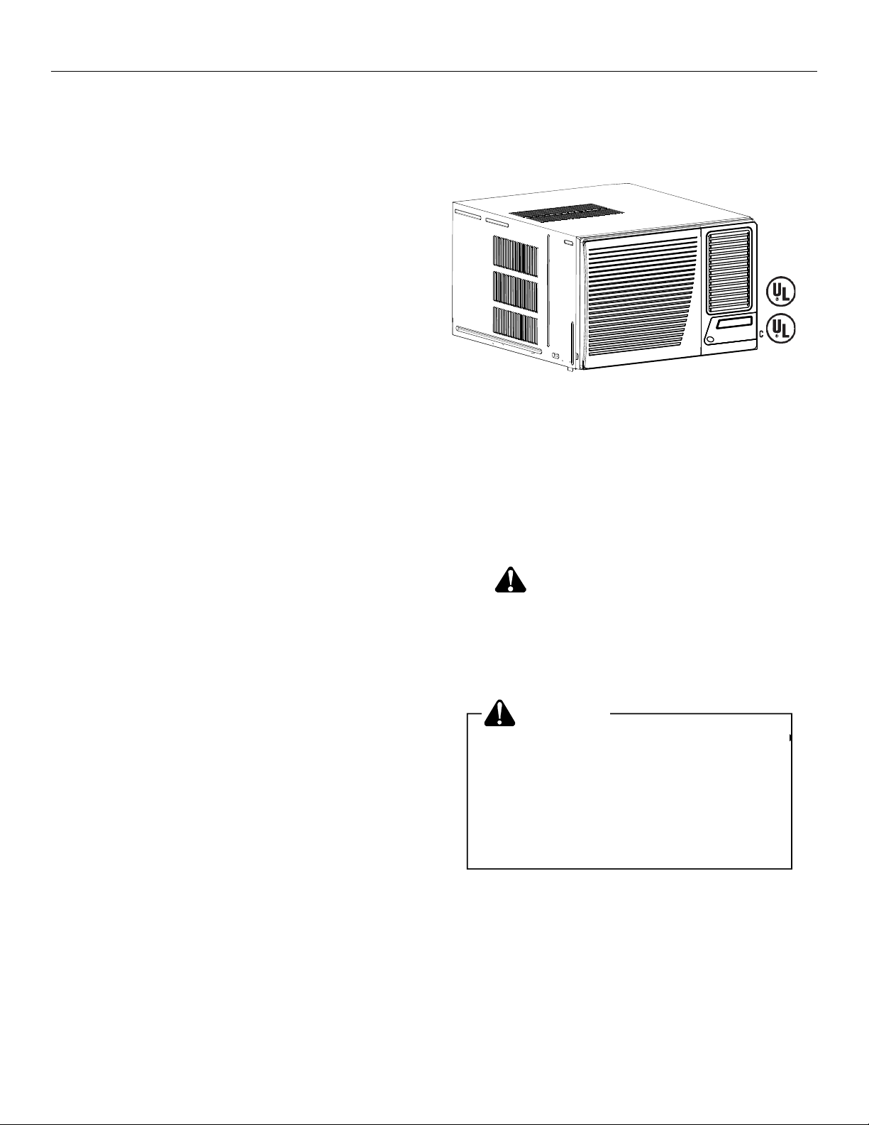
Introduction
Room air conditioners cool, dehumidify, and filter air inside
Room air conditioners cool, dehumidify and lter air inside
your home. Heat pump and electric heat models offer both
your home. Heat pump models offer both heating and cool-
heating and cooling. Opening sections of manual provide
ing. The opening sections of this manual provides some
general information for all room air conditioner models. The
general information for all room air conditioner models.
Operating Controls section describes operation of controls
Operating Controls section describes operation of controls
for each model. After reading the opening sections, turn to
for each model. After reading the opening sections, turn to
the Operating Controls section and nd the panel layout
Operating Controls section and find the panel layout that
that matches your model.
matches the model of your unit.
Read entire manual thoroughly before beginning installation
and operation of your new room air conditioner. Be sure you
have all necessary tools and materials on hand for the job.
Study illustrations to familiarize yourself with important
details of the installation process. Review manual for operating instructions.
NOTE
1. Mechanical experience is required to install air conditioner.
2. Installation can take from 1 to 3 hours, depending on
installer’s knowledge and skill.
3. If you encounter problems during installation, call our
If you encounter problems during installation, call our
consumer information line at (86-756) 8617555.
consumer information line at (517) 787-2100 and ask for
If your problem cannot be resolved by phone, contact an
the technical service deparment. If your problem cannot
authorized GREE
be resolved by phone, contact an authorized servicer.
will be at your expense.
®
brand servicer. Contact and service
15
16
Safety Information
16
Be sure electrical service is adequate for chosen model of air
17
conditioner. Complete electrical rating for unit is found on
serial plate located behind front grille. Electrical outlet must
be close enough to unit for power cord to reach without strain.
Air conditioner should be the only appliance on individual
circuit.
For personal safety and to avoid possible damage to appliance or home, observe all safety instructions highlighted by
symbol shown below.
RECOGNIZE THIS SYMBOL AS A
SAFETY PRECAUTION.
After installing unit, reread instructions to ensure each step
is complete and that all parts are fastened in place. For best
results and to minimize installation time, perform all procedures in the order shown.
WARNING
To prevent heat related illness or death, do
To prevent heat related illness or death,
do not use this device unattended.
not use this device for unattended cooling
Failure of an unattended air conditioner
of persons or animals unable to react to
may result in extreme heat in area
product failure. Failure of unattended air
intended for cooling, causing heat related
conditioner may result in extreme heat in
illness or death of persons or animals.
area intended for cooling, causing heat-
related illness or death of persons or
animals.
1
Page 4
Owner’s Manual Room Air Heat Pump with R-410A Heat Controller, Inc.
WARNING
HIGH TEMPERATURE STRESS HAZARD
This room air conditioner is not meant to
provide unattended cooling or life support
for persons or animals that are unable to
react to failure of the product.
The failure of an unattended air conditioner
may result in extreme heat in the conditioned space causing overheating or
death of persons or animals.
Precautions must be taken to ward off or
guard against such an occurrence.
Unpacking
Unpack and visually inspect the unit. Report any damage to
Unpacking
the delivering carrier immediately. If your unit is not damaged,
Unpack and visually inspect the unit. Report any damage to
remove and disgard all packing materials. On some models
the delivering carrier immediately. Remove and discard all
the air conditioner front and/or mounting kit hardware may be
packing material. On some models the air conditioner front
packed separately.
and/or mounting kit hardware may be packed separately.
Record the model and serial numbers of your unit in the space
Record the model, serial and manufacturing numbers of your
provided. This information is found on a nameplate visible after
unit in the space provided below. This information is found on
the front of the air conditioner has been removed. The rated
a nameplate visible after the front of the air conditioner has
voltage, amperage and capacity for your specic model can
been removed. The rated voltage, amperage and capacity for
also be found on this nameplate. Read the warranty packaged
your specific model can also be found on this nameplate.
with the unit. Register your unit and keep the warranty and a
Read the warranty packaged with the unit. Keep the warranty
copy of your sales receipt for future reference. You may also
and a copy of your sales receipt for future reference. You may
want to record in the space provided the date purchased and
also want to record in the space provided the date purchased
the selling dealer.
and the selling dealer.
OWNER'S PRODUCT IDENTIFICATION
MODEL NUMBER
SERIAL NUMBER
MANUFACTURING NUMBER
Owner's Name
Address
City State Zip
/ /
Date of Purchase
Authorized Dealer
Address
WARNING
To avoid death, personal injury or property
damage due to electrical shock:
Observe all local codes and ordinances.
•
Disconnect electrical power to unit before servicing.
•
•
Ground appliance properly.
Check with a qualified electrician if you are not
•
sure this appliance is properly grounded.
DO NOT ground to gas line.
•
DO NOT ground to cold water pipe if pipe is
•
interrupted by plastic, non-metallic gaskets, or
other insulating (non-conducting) materials.
•
DO NOT modify plug on power cord. If plug
does not fit electrical outlet, have proper outlet
installed by qualified electrician.
DO NOT have a fuse in the neutral or ground
•
circuit. A fuse in the neutral or ground circuit
could result in an electrical shock.
DO NOT use an extension cord with this appliance.
•
DO NOT use an adapter plug with this appliance.
•
DO NOT pinch power cord.
•
DO NOT REMOVE warning tag from power cord.
•
Electrical Requirements
Grounding Instructions
This appliance is equipped with a three-prong grounding plug
for protection against possible shock hazards. If a two-prong
wall receptacle is encountered, the customer is required to
contact a qualified electrician and have the two-prong wall
receptacle replaced with a properly grounded three-prong
wall receptacle in accordance with the National Electrical
Code.
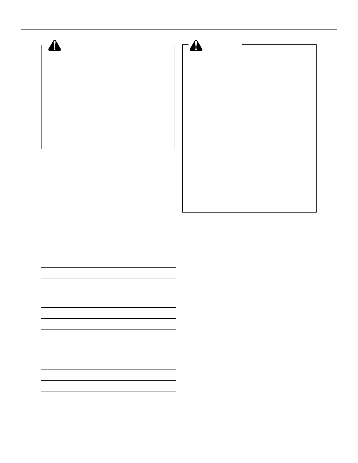
Room air conditioners are designed to operate according to
requirements on the nameplate and as shown in Table 1.
Fuse or circuit breaker ratings must be according to the fuse
instruction label and as shown in Table 1. Do not plug models
marked “Use on Single Outlet Circuit Only” into a circuit with
another appliance or light fixture.
Receptacle Wiring
Receptacle wiring must be of adequate size for unit. Refer
to unit identification plate for exact power requirements.
Minimum size of wiring, based on power requirements, is:
Units up to 20 amps: 12 gauge
20–30 amp units: 10 gauge
City State Zip
( )
Phone Number
LCDI or AFCI Power Cords
Underwriters Laboratories (UL) and the National Electric
Code (NEC) now require power cords that sense current
leakage and can open the electrical circuit to the unit. In the
leakage and be able to open the electrical circuit to the unit. In the
2
Page 5
Heat Controller, Inc. Room Air Heat Pump with R-410A Owner’s Manual
Room Heat Pumps
Heat pumps work by moving heat instead of creating it. In the
summer, the cool indoor coil absorbs heat from your room
and moves it outdoors, providing cooling. In the winter, heat
pumps reverse this operation. By lowering the temperature
of the outdoor coil below the outdoor temperature, the heat
pump absorbs the heat from outdoors and moves it inside
your house. This heat transferring process is very efficient.
For example, at 45°F outdoor temperature, a heat pump can
provide 2 ½ watts of heat for every watt of electricity it
consumes.
As outdoor temperatures drop, the heating capacity and
efficiency of the heat pump declines. At temperatures below
45°F, it is likely that ice will form on the outdoor coil. Heat
pump units are designed to operate as a heat pump above
approximately 40°F. Below 40°F, these units switch auto-
matically from reverse cycle heat pump to auxiliary electric
heating. No defrost is required. There is no minimum
Unit Plug Receptacle Circuit Rating, Voltage
Unit Plug Receptacle Circuit Rating, Voltage
Type Required Breaker, Time Rating On
Type Required Breaker, Time Rating On
NEMA No. 5-15P NEMA No. 5-15R 125V-15AMP 115V
NEMA No. 5-15P NEMA No. 5-15R 125V-15AMP 115V
NEMA No. 6-15P NEMA No. 6-15R 250V-15AMP 230/208V rated
NEMA No. 6-15P NEMA No. 6-15R 250V-15AMP 230/208V rated
NEMA No. 6-20P NEMA No. 6-20R 250V-20AMP 230/208V rated
NEMA No. 6-20P NEMA No. 6-20R 250V-20AMP 230/208V rated
NEMA No. 6-30P NEMA No. 6-30R 250V-30AMP 208V rated over
NEMA No. 6-30P NEMA No. 6-30R 250V-30AMP 208V rated over
Delay Fuse Nameplate
Delay Fuse Nameplate
at 12 amperes or
at 12 amperes or
less
less
over 12 amperes ,
over 12 amperes ,
but not more than
but not more than
16 amperes
16 amperes
16 amperes, but
16 amperes, but
not more than
not more than
24 amperes
24 amperes
event, the unit does not operate, check the reset button
located on or near the head of the power cord as part of the
normal troubleshooting procedure.
Use copper wire only. Consumer’s responsibility is to provide
proper and adequate receptacle wiring that conforms to all
applicable codes. All wiring should be installed by qualified
electrician.
Installation
Complete step-by-step installation instructions are furnished
with your unit. These instructions will be found on a separate
page included with this manual or in the mounting kit
assembly. Follow these instructions carefully. Keep these
instructions with this manual for future reference. Your unit
will be one of the following three designs:
• Unit with a window mounting kit
These models are designed for mounting though an
opening in a wall. These units can be adapted to
window installation by using the optional window mounting kit supplied with your unit.
• Unit without a window mounting kit
No window mounting kit is supplied with the unit.
These models are designed for mounting through an
opening in a wall. These units can be adapted to
window installation by purchasing an optional window
mounting kit. Consult your dealer to choose the kit that
is appropriate for your model and installation.
• Unit with a separate sleeve
Some Builder models are designed such that the outer
case and the chassis can be purchased separately.
Through-the-wall installation instructions are included
with the outer case. These models can be adapted to
window installation by purchasing an optional mounting kit.
Room Heat Pumps
Heat pumps work by moving heat instead of creating it. In the
summer, the cool indoor coil absorbs heat from your room
and moves it outdoors, providing cooling. In the winter, heat
pumps reverse this operation. By lowering the temperature
of the outdoor coil below the outdoor temperature, the heat
pump absorbs the heat from outdoors and moves it inside
your house. This heat transferring process is very efficient.
For example, at 45°F outdoor temperature, a heat pump can
provide 2 ½ watts of heat for every watt of electricity it
consumes.
As outdoor temperatures drop, the heating capacity and
efficiency of the heat pump declines. At temperatures below
45°F, it is likely that ice will form on the outdoor coil. Heat
pump units are designed to operate as a heat pump above
approximately 40°F. Below 40°F, these units switch automatically from reverse cycle heat pump to auxiliary electric
heating. No defrost is required. There is no minimum
operating temperature.
Normal Care and Maintenance
WARNING
To avoid property damage, personal injury
To avoid property damage, personal injury
or death due to electrical shock, turn unit
or death due to electrical shock, turn fan
OFF and remove plug from wall outlet before
control OFF and remove plug from wall
inspecting unit or performing maintenance.
outlet before inspecting unit or performing
maintenance.
Annual Inspection
It is suggested that your unit be inspected by your dealer or
servicer once a year. It is advisable to have the outer case
removed and the unit thoroughly cleaned.
Note: The life of your unit may be greatly reduced if you live in a
Note: The life of your unit may be greatly reduced if you live
corrosive environment such as an oceanside location with salty
in a salt air or other corrosive type environment. Under these
air. Under these conditions, the unit should be removed from its
conditions, the unit should be removed from its case and
case and completely cleaned at least once a year. At that time
completely cleaned at least once a year. At that time any
any scratches or blisters on the painted surfaces should be
scratches or blisters on the painted surfaces should be
sanded and repainted. Placing an algaecide tablet in the outdoor
sanded and repainted. Placing an algaecide tablet in the
side of the unit’s basepan is suggested in humid areas where
outdoor side of the unit’s basepan is suggested in humid
algae formation is common.
areas where algae formation is common.
3
Page 6
Owner’s Manual Room Air Heat Pump with R-410A Heat Controller, Inc.
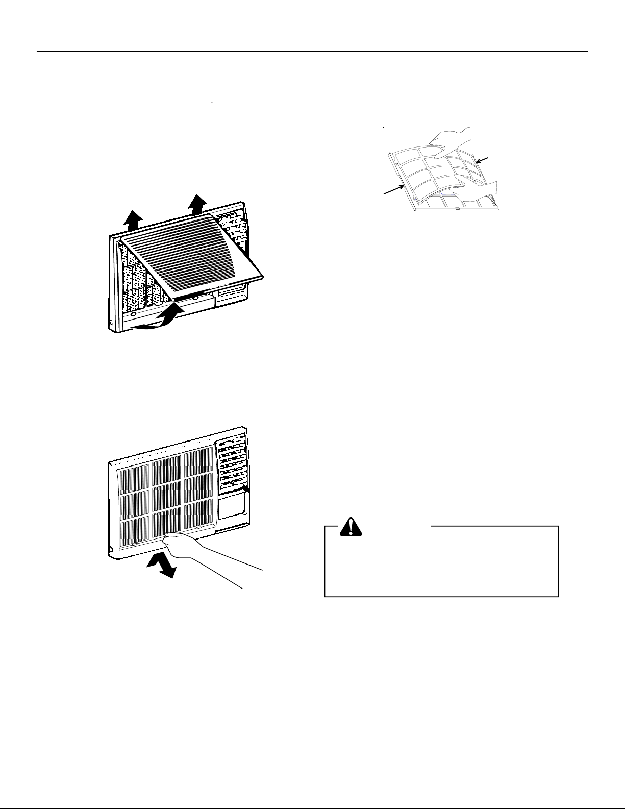
Front Grille and Filter Removal
The front contains a removable grille that provides easy
access to the air filter. To clean the filter use one of the
following methods for filter removal:
METHOD ONE
Grasp filter handle and slide filter out of unit.
Optional Air Filter Installation
Remove air filter from plastic bag. Insert three tabs
on right side of filter into three slots on filter frame. Carefully
bow middle of filter until two tabs on filter can be inserted into
two slots on filter frame. Relax bow.
Reinstall air filter and grille by reversing removal procedure.
Front Grille and Cabinet Cleaning
Grille and cabinet may be cleaned with warm water and mild
soap or detergent. Cleaning and polishing compounds are
not recommended, as they may damage plastic surfaces.
Air Filter Cleaning
A dirty air filter reduces operating efficiency of unit. Filter
should be inspected at least once every week during operation. Clean filter with vacuum cleaner or wash in warm water
and mild detergent. Filter should be thoroughly dried before
replacing in unit. Do not operate unit without filter in place.
Fan Motor Care
The fan motor is permanently lubricated for long life. There is
no need to oil the motor.
Slide-out Chassis Removal from Outer Case
1. Remove front grille by sliding grille to left and pulling out.
2. Remove air filter by sliding to left.
3. Remove four screws holding plastic front to unit and
remove front.
4. If the unit has a screw holding the basepan clip to the
chassis, remove the screw.
CAUTION
To reduce the risk of personal injury, be
To reduce the risk of personal injury be
sure to have sufcient help when moving
sure to have sufficient help when moving
your unit. A room air conditioner can be
your unit. A room air conditioner can
excessivley heavy.
weigh between 70 and 240 pounds.
5. Using basepan handle, pull chassis straight out, slowly
and evenly, until approximately 9-12 inches extends
4
Page 7

Heat Controller, Inc. Room Air Heat Pump with R-410A Owner’s Manual
from outer case. Use both hands to grasp basepan and
pull remaining chassis from outer case.
CHASSIS
PLASTICFRONT
BASEPAN
CLIP
NOTE: Basepan clip is shipped in plastic bag with mounting
screw and condensate drain cup. Install clip after reinserting
chassis into outer case to prevent accidental chassis removal.
General Operating Instructions
While operation of all units is similar, controls vary slightly
from model to model. Operating Controls section shows
control panel of unit purchased and gives detailed information
about operation of controls.
Initial Start-Up and Cooling
Select the highest fan speed and set temperature control to
its coldest position. When the desired temperature is
reached, slowly move the temperature control toward a
warmer setting until the compressor shuts off. The thermostat will then cycle the compressor on and off to maintain this
selected temperature. Adjust the fan speed for desired air
circulation.
Drain Cup Installation and Use (on some models)
Your air conditioner uses a system where the water removed
from the indoor air (condensate) is channeled to the outdoor
side of the unit. The outdoor fan blade has a “slinger” ring
attached to it that dips into the water and slings the water onto
the outdoor coil surface. This is the sound of water you hear
during normal operation. The water quickly evaporates on
this warm surface and improves the efficiency of your air
conditioner. In normal conditions the unit can evaporate the
water as fast as it is removed from the indoor air.
However, in very humid conditions excess amounts of water
may drip off the unit chassis. If this proves to be a problem,
install the condensate drain cup included with the unit to
route excess water where it would not be a problem (see
illustration below).
To install, remove the unit chassis from the outer case. Insert
the condensate drain cup through the recessed ½” hole on
the right side bottom flange of the outer case. Once inserted,
place a ½” diameter hose or tube on the drain cup bottom
spout. The hose allows you to route where you want the
excess water to go. Reinsert the unit chassis into the outer
case. The unit basepan overflow hole will be positioned
directly above the drain cup and will catch any water that
might run out.
Condensate
Drain Cup
Outer Case
BAFFLES
OUTDOOR
LOUVERS
INDOOR
GRILLE
Changing Airflow Direction Baffles
Airflow on unit may be diverted left or right from center by
baffles. Upward and downward air discharge is provided by
tilting louvers. Adjust baffles and tilt louvers for desired
airflow pattern.
Airflow Around Unit
Check the indoor grille and outdoor louvers for obstructions to
airflow. Do not block the airflow to and from the unit. If air is
obstructed and/or deflected back into the unit, the air
conditioner’s compressor may cycle on and off rapidly. This
could damage your unit.
1/2" Diameter
Hose
Switchover Thermostat Control
Emergency heat switch overrides heat pump (compressor)
and starts auxiliary electrical heater. When switch is ON,
heat pump is locked out.
• Use emergency switch only when heat pump fails to
provide adequate heat. Cause of heat pump malfunction should be determined by authorized servicer. Cost
of operating unit will increase when emergency heat
switch is engaged.
To access and engage emergency switch:
1. Remove front grille, air filter, and plastic front, as de-
scribed in Installation Instructions.
2. Remove basepan clip.
3. Slide chassis out of case about two inches.
4. Locate access hole for emergency switch above label on
right front of control box.
5. To start emergency heat, insert flathead screwdriver into
slot and turn counterclockwise until switch-stop is reached.
6. Return chassis to case.
7. Replace basepan clip, plastic front, air filter, and front
grille.
5
Page 8

Owner’s Manual Room Air Heat Pump with R-410A Heat Controller, Inc.
Air Conditioner
CAUTION:
Do not , unde r any circumstances , cut or
remove the third (ground) prong from the
power cord.
Do not change the plug on the power cord
of this air conditioner.
Aluminum house wiring may present special
problem s —consult a qualified electrician.
Air Conditioner
CAUTION:
Do not , unde r any circumstances , cut or
remove the third (ground) prong from the
power cord.
Do not change the plug on the power cord
of this air conditioner.
Aluminum house wiring may present special
problem s —consult a qualified electrician.
TOOLS YOU WILL NEED
Phillips head screwdriver
Ruler or ta pe m eas urePe ncil
Level Scis sors o r kni fe
Flat-blad e scre wd river
Adjustable wrench
Installation
Ins tructions
Question? Consumer information line (86-756) 8617555(Customer Service Center)
BEFORE YOU BEGIN
Rea d thes e instructions co mpletely
and carefully.
●
IMPORTANT — Save these
instructions for local inspector's use.
●
IMPORTANT— Observe all
gove rn ing codes and ordina nces.
●
Note to Installer — Be sure to leave these
instructions with the Co ns u mer .
●
Note to Consumer
instructions for future reference.
●
Skill level — Installation of this appliance
requires basic mechanical skills.
●
Completion time
●
We recommend that two people install
this pr oduc t.
●
Proper installation is the responsibility
of the installer.
●
Product failure due to improper installation
is not covered under the Warranty.
— Keep these
— Approximately 1 hour
ELECTRICAL REQUIREMENTS
517-787-2100
Air Conditioner
CAUTION:
Do not , unde r any circumstances , cut or
remove the third (ground) prong from the
power cord.
Do not change the plug on the power cord
of this air conditioner.
Aluminum house wiring may present special
problem s —consult a qualified electrician.
Power cord incl udes a c urrent interr upter
TOOLS YOU WILL NEED
device. A test and reset button is provided on
the plug case. The device should be tested on a
periodic basis by first pressing the TEST button
and then the RESET button. If the TEST button
does not trip or if the RESET button will not stay
engaged, discontinue use of the air conditioner
and contact a qualified service technician.
Phillips head screwdriver
TOOLS YOU WILL NEED
Adjustable wrench
Flat-blad e scre wd river
Adjustable wrench
Ruler or ta pe m eas urePe ncil
The 3-prong grounding plug minim izes the
pos sibility of electric shock hazard. If the w all
outlet you plan to us e is only a 2-prong outlet,
it is your responsibility to have it replaced with
a properly grounded 3-prong wall outlet.
Some m odels require 230/208-v olt a.c.,
protected with a time delay fuse or circuit
breaker. Thes e models should be installed
on their own s ingle branch circuit for
bes t performance and to prevent
overloa ding hous e or apartment wiring
circuits, w hich could caus e a poss ible
fire hazard from overheating wi
res .
Level Scis sors o r kni fe
Phillips head screwdriver
Power cord incl udes a c urrent interr upter
device. A test and reset button is provided on
the plug case. The device should be tested on a
periodic basis by first pressing the TEST button
and then the RESET button. If the TEST button
does not trip or if the RESET button will not stay
engaged, discontinue use of the air conditioner
and contact a qualified service technician.
6
Level Scis sors o r kni fe
Flat-blad e scre wd river
Flat-head screwdiver
Ruler or ta pe m eas urePe ncil
Page 9
Heat Controller, Inc. Room Air Heat Pump with R-410A Owner’s Manual
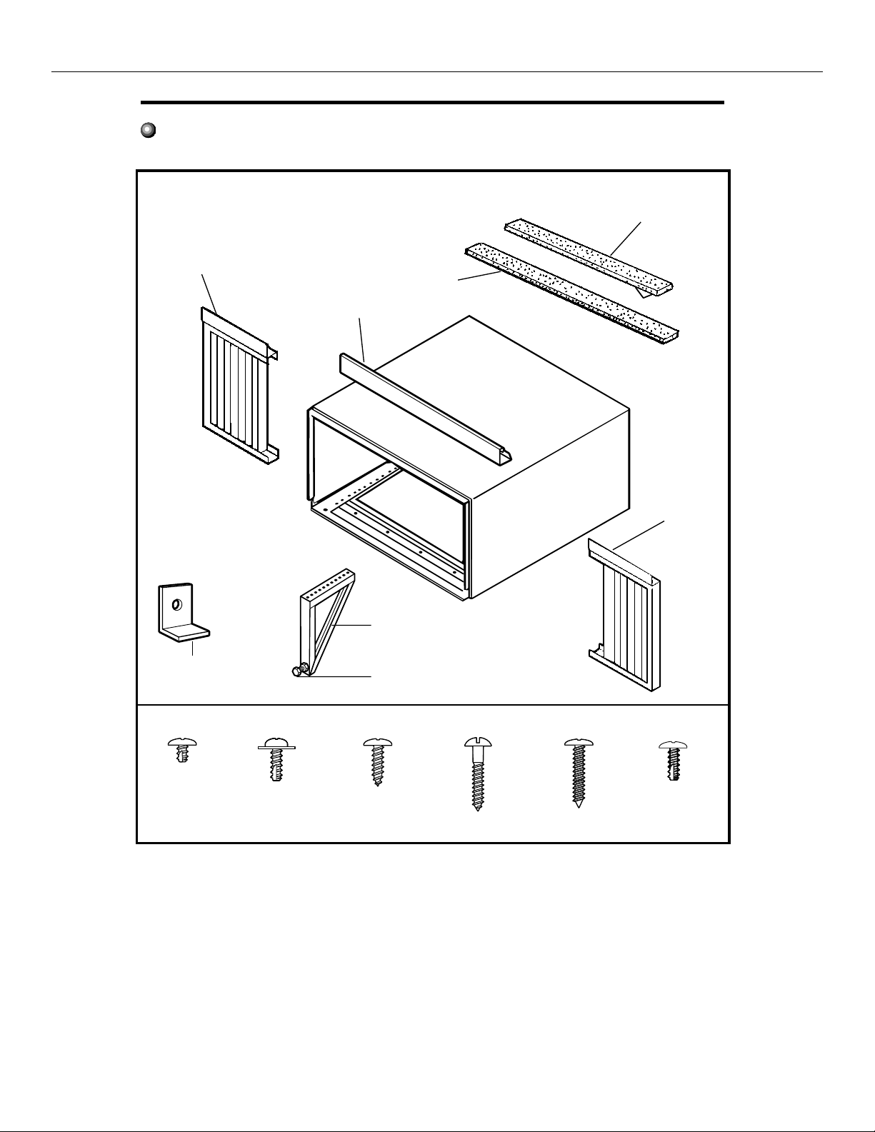
Installation Instructions
PARTS INCLUDED
(Appearance may vary)
Left
accordion
pa nel
Top
mounting
rail
Window
sash seal
Foam top
window gasket
Right
accordion
panel
Window lockin g
bracket ( 2)
Typ e A (6)
V-support (2)
Bolt (2) & nuts (2)
Typ e B (4) Typ e C (7) Type E (
Typ e D (6)
Type E (4)
Type F (2)
7
Page 10

Owner’s Manual Room Air Heat Pump with R-410A Heat Controller, Inc.
Installation Instructions
1
WINDOW REQUIREMENTS
●
Thes e instructions are for a s tandard
double-hung w indow. Yo u will need to
modify them for other types of w indows.
●
T he air co nd itioner ca n be in s tal led
without the accordion panels if needed
to fit in a narrow window. See the
window opening di mensions .
●
All supporting parts must be secured
to firm woo d, m a sonry o r m etal.
●
T he elec tri ca l o utlet m ust b e w ithin
re ac h o f th e pow er cord.
173/8" min.
30" to 3 8.1"
(With a ccordi on pa nels)
26” min.
(Without accordion panels)
26" min.
(Without a ccordion panels )
2
STORM WINDOW REQUIREMENTS
A s torm w indo w frame w ill not a llow th e
ai r c on ditioner to tilt tow a rd the outs id e,
an d w ill keep it fro m draining properly.
To a djus t for this , a ttach a piece of w oo d
to th e s tool.
WOOD PIECES-
WIDTH: 2"
LENGTH: Long enough to fit inside the
window frame.
THICKNESS : To determine the thickness,
place a piece of wood on the stool t o
make it 1/2" higher than the top of the
stor m w indow fram e.
Attac h s ecurely w ith nails or s crews
prov ided by th e ins taller.
1/2 " h igher
tha n fra m e
Stoo l
W ood
3
REMOVE THE AIR CONDITIONER
FROM THE CASE
Remove the locking screw and locking
Remove the locking screw and lock-
A
bracket from the lower frame. Save to
ing bracket from the lower frame.
reinstall later.
Save to reinstall later.
Remove the ground screw and save to
Remove the ground screw. Save to
B
reinstall later.
reinstall later.
Remove the ground screw
and save to reinstall later
Slide the air conditioner from the cas e by
C
gripping the base pa n handle and pulling
forward while bracing the case.
4
PREPARE THE WINDOW
Cut the window sas h seal to the proper
length. Peel off the backing and attach the
seal to the underside of the w indow s as h.
unit
Stor m
wi ndow
fram e
8
Page 11

Heat Controller, Inc. Room Air Heat Pump with R-410A Owner’s Manual
Installation Instructions
5
PREPARE THE CASE
Ins tall the top m ounting rail w ith 4 type B
A
screw s from the ins ide of the case.
Insert the frames for the accordion panels
B
into the top mounting rail and the bottom
frame guides. Attach the accordion panels
to the side of the case using 3 type A screws
on ea ch side.
Note: When attaching the accordion panels,
make sure to only screw the inner panels
to the cas e s ides .
Top m ounting r ail
Bo ttom f ram e gu ides
6
INSTALL THE CASE
IN THE WINDOW
Carefully s lide the cas e into the w indow and
A
center the case. Lower the window behind
the top mounting rail. Pull the bottom of the
cas e forwa rd s o that the bottom m ounting
rail is tight agains t the back of the w indow
stool. Mount the case to the w indow sill us ing
4 type E screws. Drill pilot holes , if necessary.
4 type E scr ews
S tool
Make sure the bolts and nuts are a ll of the
B
wa y in both the left and right V-s upports.
Bolt and nut
Position the V-supports on the case bottom
C
so that they w ill be near the outs ide w all.
Attach a V-support to each side of the
bottom of the ca se using type C s crews ,
3 on each side.
V-su pport
9
Page 12

Owner’s Manual Room Air Heat Pump with R-410A Heat Controller, Inc.
Installation Instructions
6
INSTALL THE CASE
IN THE WINDOW
Adjust the lev eling bolts and nuts agains t the
D
outs ide wall s o that the case has a slight tilt
to the outside. Tighten nuts with an adjustable
wrench. Use a level; about a 1/2 bubble will
be the correct case slant to the outside.
Use a w ood block (obtained locally) between
E
the leveling bolts and the wall if the wall is
weak or if the w eight of the air conditioner
falls between the studs in the wall.
(cont.)
INSTALL SUPPORT BRACKETS
7
INSTALL SUPPORT BRACKETS
AND TOP WINDOW FOAM GASKET
AND THE FOAM TOP WINDOW
GAS KET
Attac h th e s uppo rt bra ckets w ith tw o
A
type D s cr ew s, one on eac h s ide.
Cut the foam top w indow ga s ket to th e
Cut the top window foam gasket to the window
B
window width.
width.
Stuff the foam be tween the glass and the
Stuff the foam between the glass and the window
C
window to prev en t air an d i ns ects fro m
to prevent air from getting into the room.
getting into the r oo m .
Extend the left and right accordion panels
F
to the vertical w indow sas hes . Drill pilot
holes and attach the top and bottom corners
with 4 type D screw s.
Top m ounting r ail
Type D
scr ew
Type D
scr ew
Type D
scr ew
Type D
scr ew
10
Page 13

Heat Controller, Inc. Room Air Heat Pump with R-410A Owner’s Manual
Installation Instructions
8
INSTALL THE AIR CONDITIONER
INS TALL THE AIR CONDITIONER
IN THE CASE
IN THE CASE
Slide the air
A
conditioner into
the case. Do not
pus h on the
controls or the
finned coils.
Make sure the
air conditioner
is firmly s eated.
Reins tall the locking bracket and s crew
B
rem oved earlier.
Reconnect the ground w ire to the a ir
C
conditioner using the screw removed earlier.
IMPORTANT: The ground wire must be
reinstalled to ensure a proper ground.
8
INSTALL THE AIR CONDITIONER
IN THE CASE
IN THE CASE (cont.)
Pull the coiled pow er cord from its shipped
G
position in the air discharge area. Attach
the front grille frame to the case by inserting
the tabs on the grille frame into the slots
on the front top of the case. Push the grille
frame in. And install the 2 type F screws at bottom
left and right side of front panel.
Guid e the le ver car efully
thr oug h the gril le fra me
as y ou p us h it in.
Secure the front grille frame to the cas e
H
with one type C screw.
(cont.)
Remove the front grille from its box and
D
rem ove the shipping tape.
Gras p the inlet grille at the bottom corners
E
and pull it forw ard. Unhook it from its top
hinges a nd set it aside.
Using the tab, p
F
to release it and pull it down and out.
ull up s l
ightly on the filter
Reins tall the filter.
I
Reins tall the inlet grille. Connect pow er.
J
11
Page 14

Owner’s Manual Room Air Heat Pump with R-410A Heat Controller, Inc.
Controls
Power Pad
Turns air conditioner on and off.
before turningit back on. Thisprevents the air conditioner
from blowing a fuse or tripping a circuit breaker.
Do not try to operate your air conditioner in the cooling mode
when outside temperature is below 61°F (16°C). Do not try to
operate your air conditioner in the heating mode when outside
temperature is over 86°F (30°C). The inside evaporator coil
will freeze up, and the air conditioner will operate properly.
Display
Shows the set temperature when in Heat/
Cool/Energy Saver mode. Shows time
remaining on the delay timer. Shows
the room temperature when in Fan Only
modes. The Set light will turn on while
setting.
Temp Increase /Decrease Pads
Use to set temperature when inHeat(on some
models)/Cool/Energy Savermode. The Setlight
will turn on while setting.
Delay Timer Increase (+) /Decrease
(Æ-)Pads
Each touch of the Increase / Decrease
pads on the unit or theIncrease
+/ Decrease –
pads on the remote control will set the delay
time when using the Delay 1–24hrtimer ( ).
TheSetlight will turn on while setting.
Fan Speed Pads
Use to set the fan speed toLow, Med, High
Light indicates the unit
is in the temperature or
delay time Set mode.
The display shows the set temperature
when in Heat/Cool/Energy Saver mode.
Shows time remaining on the delay timer.
Owner’s Manual Room Air Heat Pump with R-410A Heat Controller, Inc.
Controls
Mode Pad
Use to set the air conditioner to Cool,
Energy Saver,Fan Only Heat (on some
models) mode.
or
control panel indicate the selected settings.
Power Pad
Turns air conditioner on and off.
Lights next to the touch pads on the air conditioner
Operating yourair conditioner properlyhelps you to obtain the
best possible results.
This section explains proper air conditioner operation.
IMPORTANT:
■ If you turn off the air conditioner, wait at least 3 minutes
before turningit back on. Thisprevents the air conditioner
from blowing a fuse or tripping a circuit breaker.
■
Do not try to operate your air conditioner in the cooling mode
when outside temperature is below 61°F (16°C).Donot try to
operate your air conditioner in the heating mode when outside
temperature is over 86°F (30°C). The inside evaporator coil
will freeze up, and the air conditioner will operate properly.
NOTE: In the event of a power failure,your air conditioner will
operate at the previous settings when the power is restored.
Display
Shows the set temperature when in Heat/
Cool/Energy Saver mode. Shows time
remaining on the delay timer. Shows
the room temperature when in Fan Only
modes. The Set light will turn on while
setting.
Temp Increase /Decrease Pads
Use to set temperature when in Heat(on some
models)/Cool/Energy Savermode. The Setlight
will turn on while setting.
Delay Timer Increase (+) /Decrease
(Æ-)Pads
Each touch of the Increase / Decrease
pads on the unit or theIncrease
+/ Decrease –
pads on the remote control will set the delay
time when using the Delay 1–24hrtimer ( ).
TheSet light will turn on while setting.
Fan Speed Pads
Use to set the fan speed toLow, Med, High
orAuto on the unit. NOTE:On the remote
control, use the fan speed Increase
+ /
Decrease
– pads to set the fan speeds to
Low,Medor High. Use the Auto pad to
turn Auto fan on.
TIMER Pads
TIEMR ON—When the air conditioner is off, it
can be set to automatically come on in 0.5 to 24
hours at its previous mode and fan settings.
Operating Controls(For Electronic units)
Set
TIMER
SWING
-
FAN
SPEED
MED
HIGH
LOW
AUTO
POWER
COOL
FAN ONLY
HEAT
MODE
1-24 HR
ENERGY SAVER
TEMP/TIMER
+
Light indicates the
delay timer is set.
Light indicates the unit
is in the temperature or
delay time Set mode.
Air Conditioner Controls
Light indicates
SWING is on.
SWING Pad
Turn on to provide continuous side-to-side
air circulation. For fixed side-to-side air
direction,turn on until the desired air
direction is obtained,then turn it off.
The display shows the set temperature
when in Heat/Cool/Energy Saver mode.
Shows time remaining on the delay timer.
Shows the room temperature when in
Fan Only mode
Do not try to operate your air conditioner in the cooling mode when
outside temperature is below 61°F (16°C). Do not try to operate
your air conditioner in the heating mode when outside temperature
is over 86°F (30°C). Otherwise, the inside evaporator coil will freeze
up, and the air conditioner will operate properly.
Use to set temperature when in Heat/Cool/Energy
Saver. The SET light will turn on while setting.
Use to set the air conditioner to COOL, ENERGY
SAVER, FAN ONLY or HEAT mode
Controls
Mode Pad
Use to set the air conditioner to Cool,
Energy Saver,Fan Only Heat (on some
models) mode.
or
control panel indicate the selected settings.
Power Pad
Turns air conditioner on and off.
Lights next to the touch pads on the air conditioner
Operating yourair conditioner properlyhelps you to obtain the
best possible results.
This section explains proper air conditioner operation.
IMPORTANT:
■ If you turn off the air conditioner, wait at least 3 minutes
before turningit back on. Thisprevents the air conditioner
from blowing a fuse or tripping a circuit breaker.
■
Do not try to operate your air conditioner in the cooling mode
when outside temperature is below 61°F (16°C).Donot try to
operate your air conditioner in the heating mode when outside
temperature is over 86°F (30°C). The inside evaporator coil
will freeze up, and the air conditioner will operate properly.
NOTE: In the event of a power failure,your air conditioner will
operate at the previous settings when the power is restored.
Display
Shows the set temperature when in Heat/
Cool/Energy Saver mode. Shows time
remaining on the delay timer. Shows
the room temperature when in Fan Only
modes. The Set light will turn on while
setting.
Temp Increase /Decrease Pads
Use to set temperature when in Heat(on some
models)/Cool/Energy Savermode. The Setlight
will turn on while setting.
Delay Timer Increase (+) /Decrease
(Æ-)Pads
Each touch of the Increase / Decrease
pads on the unit or theIncrease
+/ Decrease –
pads on the remote control will set the delay
time when using the Delay 1–24hrtimer ( ).
TheSet light will turn on while setting.
Fan Speed Pads
Use to set the fan speed toLow, Med, High
orAuto on the unit. NOTE:On the remote
control, use the fan speed Increase
+ /
Decrease
– pads to set the fan speeds to
Low,Medor High. Use the Auto pad to
turn Auto fan on.
TIMER Pads
TIEMR ON—When the air conditioner is off, it
can be set to automatically come on in 0.5 to 24
hours at its previous mode and fan settings.
Operating Controls(For Electronic units)
Set
TIMER
SWING
-
FAN
SPEED
MED
HIGH
LOW
AUTO
POWER
COOL
FAN ONLY
HEAT
MODE
1-24 HR
ENERGY SAVER
TEMP/TIMER
+
Light indicates the
Light indicates the unit
is in the temperature or
delay time Set mode.
Light indicates
SWING Pad
Turn on to provide continuous side-to-side
The display shows the set temperature
when in Heat/Cool/Energy Saver mode.
Shows time remaining on the delay timer.
Shows the room temperature when in
Fan Only mode
Controls
Power Pad
Turns air conditioner on and off.
before turningit back on. Thisprevents the air conditioner
from blowing a fuse or tripping a circuit breaker.
Do not try to operate your air conditioner in the cooling mode
when outside temperature is below 61°F (16°C).Donot try to
operate your air conditioner in the heating mode when outside
temperature is over 86°F (30°C). The inside evaporator coil
will freeze up, and the air conditioner will operate properly.
Display
Shows the set temperature when in Heat/
Cool/Energy Saver mode. Shows time
remaining on the delay timer. Shows
the room temperature when in Fan Only
modes. The Set light will turn on while
setting.
Temp Increase /Decrease Pads
Use to set temperature when in Heat(on some
models)/Cool/Energy Savermode. The Setlight
will turn on while setting.
Delay Timer Increase (+) /Decrease
(Æ-)Pads
Each touch of the Increase / Decrease
pads on the unit or theIncrease
+/ Decrease –
pads on the remote control will set the delay
time when using the Delay 1–24hrtimer ( ).
TheSet light will turn on while setting.
Fan Speed Pads
Use to set the fan speed toLow, Med, High
Set
TIMER
SWING
-
FAN
SPEED
MED
HIGH
LOW
AUTO
POWER
COOL
FAN ONLY
HEAT
MODE
1-24 HR
ENERGY SAVER
TEMP/TIMER
+
Light indicates the
delay timer is set.
Light indicates the unit
is in the temperature or
delay time Set mode.
Light indicates
SWING is on.
The display shows the set temperature
when in Heat/Cool/Energy Saver mode.
Shows time remaining on the delay timer.
Shows the room temperature when in
Fan Only mode
Light indicates the unit
is in the temperature or
delay time Set mode.
TIMER
.5-24 HR
Delay .5-24hr timer
Temp Increase ▲ /Decrease ▼ Pads
Use to set temperature when in Heat
The Set light will turn on while setting.
(on some models)/Cool/Energy Saver
Operating Controls(For Electronic units)
Controls
Operating yourair conditionerproperly helps you to obtain the
best possible results.
This section explains proper air conditioner operation.
Power Pad
Turns air conditioner on and off.
IMPORTANT:
■ If you turn off the air conditioner, wait at least 3 minutes
before turningit back on. Thisprevents the air conditioner
from blowing a fuse or tripping a circuit breaker.
Do not try to operate your air conditioner in the cooling mode when
■
Do not try to operate your air conditioner in the cooling mode
outside temperature is below 61°F (16°C). Do not try to operate
when outside temperature is below 61°F (16°C). Do not try to
your air conditioner in the heating mode when outside temperature
operate your air conditioner in the heating mode when outside
is over 86°F (30°C). Otherwise, the inside evaporator coil will freeze
temperature is over 86°F (30°C). The inside evaporator coil
up, and the air conditioner will operate properly.
will freeze up, and the air conditioner will operate properly.
NOTE: In the event of a power failure,yourair conditioner will
operate at the previous settings when the power is restored.
Lights next to the touch pads on the air conditioner
control panel indicate the selected settings.
The display shows the set temperature
when in Heat/Cool/Energy Saver mode.
Shows time remaining on the delay timer.
Shows the room temperature when in
Fan Only mode
Shows the room temperature when in
Fan Only mode
POWER
AUTO
HIGH
MED
LOW
FAN
SPEED
Delay 1–24hr
Delay timer
Decrease
Mode select
Fan speed
Delay 0.5–24hr
Decrease
Temperature
Delay timer
set Increase
Decrease
and Decrease
Mode select
Fan speed
Decrease
Temperature
set Increase
and Decrease
Light indicates the unit
is in the temperature or
POWER
delay time Set mode.
AUTO
HIGH
MED
LOW
FAN
SPEED
MODE
Air Conditioner Controls
Air Conditioner Controls
HEAT
COOL
ENERGY SAVER
FAN ONLY
Set
MODE
HEAT
COOL
ENERGY SAVER
FAN ONLY
Light indicates
SWING is on.
SWING
Light indicates the
delay timer is set.
SWING
Remote Control
Remote Control
Light indicates the unit
is in the temperature or
delay time Set mode.
Set
+
TEMP/TIMER
+
-
TIMER
1-24 HR
TEMP/TIMER
-
Light indicates the
delay timer is set.
TIMER
TIMER
.5-24 HR
0.5
1-24 HR
Delay timer Increase
Swing
Auto Fan on
Fan speed Increase
Delay timer Increase
Unit power on/off
Auto Fan on
Fan speed Increase
Unit power on/off
12
Display
Shows the set temperature when in Heat/
Cool/Energy Saver mode. Shows time
remaining on the delay timer. Shows
the room temperature when in Fan Only
modes. The Set light will turn on while
setting.
Press Increase(+) and Decrease (-) Pads
at the same time for 3 seconds,Temperature
display will change between ∞oÑF and oC.
Delay Timer Increase (+) /Decrease
Timer/Delay
Each touch of the Increase / Decrease
pads on the unit or theIncrease
pads on the remote control will set the delay
time when using the Delay 1–24hrtimer .
Delay 0.5-24hr
TheSetlight will turn on while setting.
Fan Speed Pads
Use to set the fan speed toLow, Med, High
orAuto on the unit. NOTE:On the remote
control, use the fan speed Increase
Decrease
Low,Medor High. Use the Auto pad to
turn Auto fan on.
Mode Pad
Use to set the air conditioner to Cool,
Use to set the air conditioner to COOL, ENERGY
Energy Saver,Fan Only Heat (on some
SAVER, FAN ONLY or HEAT mode
models) mode.
Timer/Delay Pads
TIMER Pads
Timer/Delay On —When the air conditioner is off, it
TIEMR ON—When the air conditioner is off, it
can be set to automatically come on in 0.5 to 24
hours at its previous mode and fan settings.
– pads to set the fan speeds to
or
SWING Pad
Turn on to provide continuous side-to-side
air circulation. For fixed side-to-side air
direction,turn on until the desired air
direction is obtained,then turn it off.
(Æ-)Pads
+/ Decrease –
timer
+ /
Page 15

Heat Controller, Inc. Room Air Heat Pump with R-410A Owner’s Manual
Timer/Delay OFF—When the air conditioner is on,
TIMER OFF—When the air conditioner is on,
itcanbesetto automatically turn off in 0.5 to
24 hours.
How to set:
Press the TIMER 1–24hr pad on the unit or
TIMER
the pad on the remote control. Each
0.5- 24HR
touch
of the Increase / Decrease pads on the
unit or the Increase
0.5
TIMER -24hr
DELAY
+ / Decrease –pads on
the remote control will set the timer in
0.5 hour or 1 hour intervals (the intervals is
0.5 hour as the delay timer below 10 hours;
the intervals is 1 hour as the delay timer above
10 hours ). The Set light will turn on while setting.
To review the remaining time on the TIMER
-24hr timer, press the TIMER -24hr pad on the
1–24hr timer, press the TIMER 1–24hr pad on the
0.5
unit or the pad on the remote control.
TIMER
0.5- 24HR
DELAY
0.5
Use the Increase / Decrease pads on the unit
or the Increase
+ / Decrease –pads on the
remote control to set a new time if desired.
To cancel the timer, press the TIMER 1–24hr pad
until the light on the TIMER1–24hr pad goes off.
TIMER 0.5-24hr
TIMER 0.5-24hr
Remote Control
To ensure proper operation, aim the remote
control at the signal receiver on the air
conditioner.
The remote control signal has a range of
up to 20 feet.
Make sure nothing is between the air conditioner
and the remote control that could block the
signal.
Make sure batteries are fresh and installed
fresh
correctly as indicated on the remote control.
Cool Mode
Use the Coolmode at Low, Med, High orAuto Fan
Speed for cooling. Use the Temperature Increase
/Decrease pads to set the desired temperature
between 61°F and 86°F in 1°F increments.
The compressor will cycle on and off to keep
the room at the set level of comfort.
Set the thermostat at a lower number and the indoor
air will become cooler. Set the thermostat at a higher
number and the indoor air will become warmer.
NOTE:If the air conditioner is off and is then turned on
while set to a Cool setting or if turned from a fan setting
to a Coolsetting, it may take approximately 3 minutes
for the compressor to start and cooling to begin.
This time delay is required to protect the compressor.
Cooling Descriptions
For Normal Cooling—Select the Cool mode and
Highor Med fan with a middle set temperature.
For Maximum Cooling—Select the Cool mode
andHighfan with a lower set temperature.
For Quieter & Nighttime Cooling—Select the
Coolmode and Lowfan with a middle set
temperature.
Energy Saver Mode
Controls the fan.
ON—The fan will cycle on and off with the
compressor. This results in wider variations of
room temperature and humidity. Normally used
when the room is unoccupied.NOTE: The fan may
continue to run for a short time after the compressor cycles off.
OFF—The fan runs all the time, while the
compressor cycles on and off.
Fan Only Mode
Use the Fan Only Mode at Low, Med or Highfan
speed to provide air circulation and filtering
without cooling. Since fan only settings do not
provide cooling, a Set temperature cannot be
entered. The room temperature will appear
in the display.
NOTE: Auto Fan Speed cannot be used when in the
Fan Only Mode.
Heat Mode (On some models)
Use the Heat mode at Low, Med, High or Auto Fan
Speed for heating. Use the
/Decrease
pads to set the desired temperature
Temperature Increase
between 61°F and 86°F in 1°F increments.
Auto Fan Speed
Set to Auto fan speed for the fan speed to auto-
matically set to the speed needed to provide opti-
mum comfort settings with the set temperature.
If the room needs more cooling, the fan speed
will automatically increase. If the room needs less
cooling, the fan speed will automatically decrease.
NOTE: Auto Fan Speed cannot be used when in the
Fan Only Mode.
Power Outage Recovery Feature
In the case of a power outage or interruption, the
unit will automatically re-start in the settings last
used after the power is restored. If the
feature was set, it will resume countdown. You may
need to set a new time if desired.
Timer/Delay0.5-24hr
13
Page 16

Owner’s Manual Room Air Heat Pump with R-410A Heat Controller, Inc.
Temperature Control
Slide this control to the left for a warmer room temperature,
to the right for a cooler room temperature.
exhaust stale or smoky air. To conserve energy, it is advised
Vent Control
Choose one of the following two settings by sliding the vent
control under the appropriate marking:
OPEN
circulates and filters room air. This position can be used to
that the Fan Control be in the Fan Only setting when using
this feature.
CLOSE
filters room air. This position should be used for normal
cooling operation.
– Exhausts room air to the outdoors. Also
– Exhaust damper is closed. Unit circulates and
14
Page 17
Heat Controller, Inc. Room Air Heat Pump with R-410A Owner’s Manual
Troubleshooting
Before Calling Service
WARNING
To reduce the risk of electric shock, personal injury, or death, turn the fan control to the
off position and remove the unit plug from the wall outlet before doing any inspection or
maintenance work.
The following is a list of problems that are sometimes encountered when using a room air conditioner. Possible cause and
suggested remedies are given for each problem.
If the problem cannot be fixed using the suggested remedies, see WHEN SERVICE IS REQUIRED section.
PROBLEM POSS IBLE CAUSE SUGGESTED REME DY
UNIT WILL N OT RUN No power to unit Push reset button on power cord.
Set Fan Control to any position other than OFF.
Set Fan Control to position other than OFF.
Make sure plug is firm ly seated in outlet.
Check for blown fuses, tripped circuit breakers.
LITTLE OR NO COO LING
LITTLE OR NO HEATING
(fan and compressor run)
LITTLE OR NO COOLING
LITTLE OR NO HEATING
(only fan runs )
NOISY UNIT Loose front on mounting assembly
Fresh air/exhaust damper open
Obstructed indoor or outdoor airflow
Dirty air filters
Unit undersized for application
Temperature Control not set properly For cooling, turn Tem perature Control to cooler setting.
Front panel may be loose
Set vent to CLOSED.
Remove obstruction from indoor grille or outdoor louvers.
Dirty air filter. Clean or replac e, as needed.
Check with dealer to determine proper capacity unit for application.
For heating, turn Tem perature Control to warm er setting.
Tighten any loose parts.
Weak buildin g construction
Water hitting fan blade
Unit oversized for application:
compressor c ycles on and off frequently
MOUN TING SUPPO RT NOT
INSTALLED
FROS T ON INDOOR COIL Dirty air filter
FROS T ON OUTDOOR COIL
(heat pump m odels only)
ODOR S IN COOLING Mold, mildew, or algae formation on wet
ODOR S IN HEATING Normal for first time electric heater is
Storm window frame installed in window Some models require rem oval of storm window fram e before
Normal for low outdoor temperatures
Normal for outdoor temperatures at or
below 45°F
surfaces
used each season
When Service Is Required
Your room air conditioner dealer can give you the name of
Call 866-557-1865 for service and warranty. Help them
your nearest Authorized Service Center. Help them give
give you prompt service by providing:
you prompt service by providing:
• An accurate description of problem.
• Complete model, serial, and manufacturing (P) num-
Complete model and serial number from
serial plate
bers from serial plate.
• Proof of purchase (sales receipt) upon request.
Repair by unauthorized servicer that results in subsequent
failure of unit voids warranty. Warranty details are contained in warranty certificate enclosed with unit.
Keep accurate records of service calls, including what was
done, servicer’s name, and date of service.
Provide additional support for unit.
Normal in high humidity. Stop noise by removing drain plug or
adding condensate drain cup.
Check with dealer to determine proper capacity unit for application.
installation.
Clean air filter by vacuuming or washing with water and mild soap.
Turning Temperature Control to warm er setting reduces occurrence
and duration of frost.
Call for service only if unit does not heat room and you have
check ed all problems and rem edies listed under LITTLE OR NO
HEATING.
To reduce algae growth, use algaecide tablet in base pan; remove
drain plug; add condensate drain cup and hose. Thoroughly clean
unit.
Caused by dust accumulation during unused months.
Odor dissipates quick ly with heater use.
Any Questions?
Most questions can be answered by your local dealer. If you
have other matters that cannot be resolved locally, or you
need additional information regarding other heating and
cooling products offered by us - please call:
Heat Controller, Inc.
CONSUMER INFORMA
Customer or Technical Service Department
Tel: (86-756) 8617555 (Customer Service Center)
Web Site: http://www.gree.com.cn
517-787-2100
TION LINE
15
Page 18

Owner’s Manual Room Air Heat Pump with R-410A Heat Controller, Inc.
THIS PAGE WAS LEFT INTENTIONALLY BLANK
16
Page 19

Heat Controller, Inc. Room Air Heat Pump with R-410A Owner’s Manual
THIS PAGE WAS LEFT INTENTIONALLY BLANK
17
Page 20
07/2010 66129905195
 Loading...