

Page 1
WARNING
ea r th fr i e n d l y r e f r ig er a nt
earthry r
dlynfr
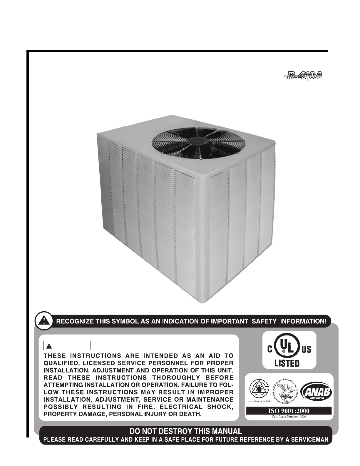
HEAT CONTROLLER
INSTALLATION INSTRUCTIONS
HIGH-EFFICIENCY CONDENSING UNITS FEATURING
EARTH-FRIENDLY R-410A REFRIGERANT
RSG - 61⁄2 & 71⁄2 TON
[ ] INDICATES METRIC CONVERSIONS
SUPERSEDES 92-42665-14-00
92-42665-14-01
Page 2
TABLE OF CONTENTS
I. SAFETY INFORMATION . . . . . . . . . . . . . . . . . . . . . . . . . . . . . . . . . . . . . . . . . . . 3
II. INTRODUCTION . . . . . . . . . . . . . . . . . . . . . . . . . . . . . . . . . . . . . . . . . . . . . . . . . . 4
II. CHECKING PRODUCT RECEIVED . . . . . . . . . . . . . . . . . . . . . . . . . . . . . . . . . . . 4
I
IV. EQUIPMENT PROTECTION . . . . . . . . . . . . . . . . . . . . . . . . . . . . . . . . . . . . . . . . 4
V. WHY USE AN AIR COOLED SPLIT SYSTEM?. . . . . . . . . . . . . . . . . . . . . . . . . . 5
VI. STANDARD UNIT FEATURES - 6
VII. INSTALLATION . . . . . . . . . . . . . . . . . . . . . . . . . . . . . . . . . . . . . . . . . . . . . . . . . . 7
A. Important Message to Owner . . . . . . . . . . . . . . . . . . . . . . . . . . . . . . . . . . . . . . 7
B. Inspection and Handling . . . . . . . . . . . . . . . . . . . . . . . . . . . . . . . . . . . . . . . . . . 7
C. Order Parts . . . . . . . . . . . . . . . . . . . . . . . . . . . . . . . . . . . . . . . . . . . . . . . . . . . 8
D. Standard Items . . . . . . . . . . . . . . . . . . . . . . . . . . . . . . . . . . . . . . . . . . . . . . . . . 8
. General Installation . . . . . . . . . . . . . . . . . . . . . . . . . . . . . . . . . . . . . . . . . . . . . . 8
E
F. Rooftop Installation. . . . . . . . . . . . . . . . . . . . . . . . . . . . . . . . . . . . . . . . . . . . . . 8
G. Slab Installation . . . . . . . . . . . . . . . . . . . . . . . . . . . . . . . . . . . . . . . . . . . . . . . . 8
VIII. REFRIGERANT PIPING DATA . . . . . . . . . . . . . . . . . . . . . . . . . . . . . . . . . . . . . . 9
A. Installation of Piping . . . . . . . . . . . . . . . . . . . . . . . . . . . . . . . . . . . . . . . . . . . . 10
B. Typical Piping Recommendations . . . . . . . . . . . . . . . . . . . . . . . . . . . . . . . . . 11
VIX. WIRING . . . . . . . . . . . . . . . . . . . . . . . . . . . . . . . . . . . . . . . . . . . . . . . . . . . . . . . . 13
X. ELECTRICAL POWER . . . . . . . . . . . . . . . . . . . . . . . . . . . . . . . . . . . . . . . . . . . . 13
XI. POWER WIRING . . . . . . . . . . . . . . . . . . . . . . . . . . . . . . . . . . . . . . . . . . . . . . . . 13
XII. WIRE ROUTING . . . . . . . . . . . . . . . . . . . . . . . . . . . . . . . . . . . . . . . . . . . . . . . . . 13
XIII. GROUNDING . . . . . . . . . . . . . . . . . . . . . . . . . . . . . . . . . . . . . . . . . . . . . . . . . . . 13
XIV. THERMOSTAT - 6
XV. LEAK TESTING . . . . . . . . . . . . . . . . . . . . . . . . . . . . . . . . . . . . . . . . . . . . . . . . . 13
XVI.R-410A REFRIGERANT . . . . . . . . . . . . . . . . . . . . . . . . . . . . . . . . . . . . . . . . . . . . 14
A. Tools Required for Installing & Servicing R-410A Models . . . . . . . . . . . . . . . 14
B. Specification of R-410A . . . . . . . . . . . . . . . . . . . . . . . . . . . . . . . . . . . . . . . . . 14
C. Quick Reference Guide for R-410A . . . . . . . . . . . . . . . . . . . . . . . . . . . . . . . . 14
D. Replacement Units . . . . . . . . . . . . . . . . . . . . . . . . . . . . . . . . . . . . . . . . . . . . . 15
E. Evaporator Coil . . . . . . . . . . . . . . . . . . . . . . . . . . . . . . . . . . . . . . . . . . . . . . . . 15
XVII. EVACUATION & CHARGING . . . . . . . . . . . . . . . . . . . . . . . . . . . . . . . . . . . . . . 15
XVIII. SEQUENCE OF OPERATION - 6
XIX. ACCESSORIES . . . . . . . . . . . . . . . . . . . . . . . . . . . . . . . . . . . . . . . . . . . . . . . . . 17
A. Anti-Short Cycle Timer . . . . . . . . . . . . . . . . . . . . . . . . . . . . . . . . . . . . . . . . . . 17
B. Liquid Pressure Control . . . . . . . . . . . . . . . . . . . . . . . . . . . . . . . . . . . . . . . . . 18
C. Liquid Line Solenoid Valve . . . . . . . . . . . . . . . . . . . . . . . . . . . . . . . . . . . . . . . 18
D. Sight Glass / Moisture Indicator . . . . . . . . . . . . . . . . . . . . . . . . . . . . . . . . . . . 18
XX. MISCELLANEOUS . . . . . . . . . . . . . . . . . . . . . . . . . . . . . . . . . . . . . . . . . . . . . . . 19
A. Charge Charts . . . . . . . . . . . . . . . . . . . . . . . . . . . . . . . . . . . . . . . . . . . . . . 19-20
B. Maintenance & Operation. . . . . . . . . . . . . . . . . . . . . . . . . . . . . . . . . . . . . . . . 21
1. Contactor . . . . . . . . . . . . . . . . . . . . . . . . . . . . . . . . . . . . . . . . . . . . . . . . . . 21
2. HPC . . . . . . . . . . . . . . . . . . . . . . . . . . . . . . . . . . . . . . . . . . . . . . . . . . . . . . 21
3. LPC . . . . . . . . . . . . . . . . . . . . . . . . . . . . . . . . . . . . . . . . . . . . . . . . . . . . . . 21
4. Pre-Start Check . . . . . . . . . . . . . . . . . . . . . . . . . . . . . . . . . . . . . . . . . . . . . 21
C. Troubleshooting . . . . . . . . . . . . . . . . . . . . . . . . . . . . . . . . . . . . . . . . . . . . . . . 22
1
⁄2 & 71⁄2 TON . . . . . . . . . . . . . . . . . . . . . . . . . . . . . . . . . . . . 13
1
⁄2 & 71⁄2 TON . . . . . . . . . . . . . . . . . . . . . . . . . 6
1
⁄2 & 71⁄2 TON . . . . . . . . . . . . . . . . . . . . . . . . 17
➤ Installation Instructions are updated on a regular basis. This is done as product
changes occur or if new information becomes available. In this publication, an arrow (➤)
denotes changes from the previous edition or additional new material.
2
Page 3
WARNING
!
IMPORTANT: ALL MANUFACTURER PRODUCTS MEET CURRENT
FEDERAL OSHA GUIDELINES FOR
SAFETY. CALIFORNIA
ROPOSITION 65 WARNINGS ARE
P
REQUIRED FOR CERTAIN PRODUCTS, WHICH ARE NOT COVERED
BY THE OSHA STANDARDS.
CALIFORNIA'S PROPOSITION 65
REQUIRES WARNINGS FOR PRODUCTS SOLD IN CALIFORNIA THAT
CONTAIN, OR PRODUCE, ANY OF
OVER 600 LISTED CHEMICALS
KNOWN TO THE STATE OF
ALIFORNIA TO CAUSE CANCER
C
OR BIRTH DEFECTS SUCH AS
FIBERGLASS INSULATION, LEAD
IN BRASS, AND COMBUSTION
PRODUCTS FROM NATURAL GAS.
ALL “NEW EQUIPMENT” SHIPPED
FOR SALE IN CALIFORNIA WILL
HAVE LABELS STATING THAT THE
PRODUCT CONTAINS AND/OR
PRODUCES PROPOSITION 65
CHEMICALS. ALTHOUGH WE HAVE
NOT CHANGED OUR PROCESSES,
HAVING THE SAME LABEL ON ALL
OUR PRODUCTS FACILITATES
MANUFACTURING AND SHIPPING.
WE CANNOT ALWAYS KNOW
“WHEN, OR IF” PRODUCTS WILL
BE SOLD IN THE CALIFORNIA
MARKET.
YOU MAY RECEIVE INQUIRIES
FROM CUSTOMERS ABOUT CHEMICALS FOUND IN, OR PRODUCED
BY, SOME OF OUR HEATING AND
AIR-CONDITIONING EQUIPMENT,
OR FOUND IN NATURAL GAS USED
WITH SOME OF OUR PRODUCTS.
LISTED BELOW ARE THOSE CHEMICALS AND SUBSTANCES COMMONLY ASSOCIATED WITH SIMILAR EQUIPMENT IN OUR INDUSTRY AND OTHER MANUFACTURERS.
• GLASS WOOL (FIBERGLASS)
INSULATION
• CARBON MONOXIDE (CO)
• FORMALDEHYDE
• BENZENE
MORE DETAILS ARE AVAILABLE
AT THE WEBSITES FOR OSHA
(OCCUPATIONAL SAFETY AND
HEALTH ADMINISTRATION), AT
WWW.OSHA.GOV
OF CALIFORNIA'S OEHHA (OFFICE
OF ENVIRONMENTAL HEALTH
HAZARD ASSESSMENT), AT
WWW.OEHHA.ORG.
EDUCATION IS IMPORTANT SINCE
THE CHEMICALS AND SUBSTANCES ON THE LIST ARE
FOUND IN OUR DAILY LIVES. MOST
CONSUMERS ARE AWARE THAT
PRODUCTS PRESENT SAFETY AND
HEALTH RISKS, WHEN IMPROPERLY USED, HANDLED AND MAINTAINED.
AND THE STATE
CONSUMER
1.0 SAFETY INFORMATION
WARNING
!
TH ESE INST RUCTIONS A RE INTENDED A S AN AID TO QUALIFIED
LIC ENSED SER VIC E P ERS ONN EL FOR PRO PER INSTALLA TIO N,
ADJUSTMENT AND OPERATION OF THIS UNIT. READ THESE INSTRUCTIONS THOROUGHLY BEFORE ATTEMPTING INSTALLATION OR OPERATION. FAILURE TO FOLLOW THESE INSTRUCTIONS MAY RESULT IN
IMPROPER INSTALLATION, ADJUSTMENT, SERVICE OR MAINTENANCE
POSSIBLY RESULTING IN FIRE, ELECTRICAL SHOCK, PROPERTY DAM-
GE, PERSONAL INJURY OR DEATH.
A
WARNING
!
DISCONNECT ALL POWER TO THE UNIT BEFORE STARTING MAINTENANCE.
FAILURE TO DO SO CAN RESULT IN SEVERE ELECTRICAL SHOCK OR
DEATH.
WARNING
!
DO NOT USE OXYGEN TO PURGE LINES OR PRESSURE SYSTEM FOR
LEAK TEST. OXYGEN REACTS VIOLENTLY WITH O IL, WHICH CAN
CAUSE AN EXPLOSION RESULTING IN SEVERE PERSONAL INJURY OR
DEATH.
WARNING
!
AFTER COMPLETION OF WIRING CHECK ALL ELECTRICAL CONNECTIONS, INCLUDING FACTORY WIRING WITHIN THE UNIT, AND MAKE
SURE ALL CONNECTIONS ARE TIGHT, REPLACE AND SECURE ALL
ELECTRICAL BOX COVERS AND ACCESS DOORS BEFORE LEAVING
UNIT OR TURNING ON POWER TO CIRCUIT SUPPLY UNIT. FAILURE TO
DO SO CAN CAUSE A FIRE OR ELECTRICAL SHOCK RESULTING IN
PROPERTY DAMAGE, PERSONAL INJURY OR DEATH.
WARNING
!
THIS UNIT MUST BE PERMANENTLY GROUNDED. A GROUND LUG IS
PROVIDED NEAR THE CONTACTOR FOR A GROUND WIRE. FAILURE TO
DO SO CAN CAUSE A FIRE OR ELECTRICAL SHOCK RESULTING IN
PROPERTY DAMAGE, SEVERE PERSONAL INJURY OR DEATH.
CAUTION
!
R-410A systems operate at higher pressures than R-22 systems. Do not use
R-22 service equipment or components on R-410A equipment.
CAUTION
!
Only use evaporators approved for use on R-410A systems. Use of existing R-22
evaporators can introduce mineral oil to the R-410A refrigerant forming two different liquids and decreasing oil return to the compressor. This can result in compressor failure.
3
Page 4
II. INTRODUCTION
This booklet contains the installation and operating instructions for your self-contained
air conditioner. There are a few precautions that should be taken to derive maximum
satisfaction from it. Improper installation can result in unsatisfactory operation or dangerous conditions.
Read this booklet and any instructions packaged with separate equipment required to
ake up the system prior to installation. Give this booklet to the owner and explain its
m
provisions. The owner should retain this booklet for future reference.
III. CHECKING PRODUCT RECEIVED
Upon receiving the unit, inspect it for any damage from shipment. Claims for damage,
either shipping or concealed, should be filed immediately with the shipping company.
Check the unit model number, electrical characteristics, and accessories to determine if
they are correct.
IV. EQUIPMENT PROTECTION FROM THE
ENVIRONMENT
The metal parts of this unit may be subject to rust or deterioration in adverse environmental conditions. This oxidation could shorten the equipment’s useful life. Salt spray,
fog or mist in seacoast areas, sulphur or chlorine from lawn watering systems, and various chemical contaminants from industries such as paper mills and petroleum refineries
are especially corrosive.
If the unit is to be installed in an area where contaminants are likely to be a problem, special attention should be given to the equipment location and exposure.
1. Avoid having lawn sprinkler heads spray directly on the unit cabinet.
2. In coastal areas, locate the unit on the side of the building away from the waterfront.
3. Shielding provided by a fence or shrubs may give some protection.
4. Elevating the unit off its slab or base enough to allow air circulation will help avoid
holding water against the basepan.
Regular maintenance will reduce the buildup of contaminants and help to protect
the unit’s finish.
WARNING
!
DISCONNECT ALL POWER TO THE UNIT BEFORE STARTING MAINTENANCE.
FAILURE TO DO SO CAN RESULT IN SEVERE ELECTRICAL SHOCK OR
DEATH.
1. Frequent washing of the cabinet, fan blade and coil with fresh water will remove
most of the salt or other contaminants that build up on the unit.
2. Regular cleaning and waxing of the cabinet with an automobile polish will provide
some protection.
3. A liquid cleaner may be used several times a year to remove matter that will not
wash off with water.
Several different types of protective coatings are offered in some areas. These coatings
may provide some benefit, but the effectiveness of such coating materials cannot be verified by the equipment manufacturer.
The best protection is frequent cleaning, maintenance and minimal exposure to
contaminants.
4
Page 5
V. WHY USE AN AIR COOLED SPLIT SYSTEM?
• With an air cooled system, you have no water or sewer connections to make, and
no troublesome and costly water treatment problems.
• Since the condensing unit is located outside the building, and the low profile air handling unit can be installed in the drop ceiling or in the conditioned space, you will not
eed a separate equipment room which takes up valuable building space.
n
• Because of the simple design of the condensing unit, installation is quick and sim-
le, and very little maintenance is required.
p
• The size ranges offered allow you to mix or match components to meet actual job
requirements, thus eliminating the need to use oversized or undersized equipment.
Equipment sized to meet the actual load will provide better operating economy, better humidity control, and longer equipment life.
• Remote mounting of the already quiet condensing unit keeps the compressor and
condenser fan noise outside, and the vertical discharge fans carry the sound up and
away from the surrounding area.
TABLE 1
CORNER WEIGHTS (Pounds)
Unit
Model
RSG078 45 [20.41] 66 [29.91] 63 [28.6] 90 [40.8]
Total Weight
Lbs. [kg]
264
ABCD
RSG090 283
Corner Weights, Lbs. [kg]
98 [44.5]63 [28.6]75 [34.0]47 [21.3]
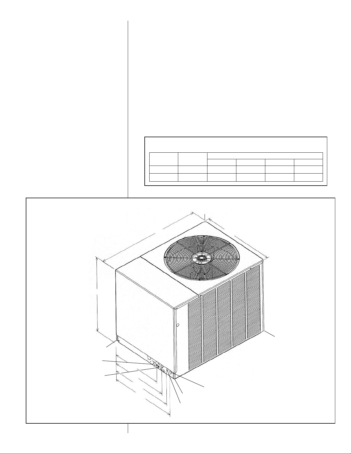
FIGURE 1
UNIT DIMENSIONS — 61⁄2 & 71⁄2 TON
3253⁄64"
SUCTION
LINE 1
LIQUID
LINE1⁄2"
C
43
42
⁄64"
D
1
⁄8"
21
11
24
⁄16"
3
⁄16"
11
26
287⁄16"
⁄16"
HIGH VOLTAGE - 1
B
LOW VOLTAGE -
7
⁄8" HOLE
1
⁄16"
31
A
3
⁄4" HOLE
5
Page 6

VI. STANDARD UNIT FEATURES — 61⁄2 AND 71⁄2
CABINET — Galvanized steel with a durable powder coat paint finish. The cabinet front
and sides are formed into a one piece unitized design with stamped louvers to provide
protection for the condenser coils.
SERVICE ACCESS — Control box with separation between line and control voltages,
as well as compressor and other refrigerant controls are accessible through removable
op and side panels (without affecting normal operation of unit).
t
Condenser fan motors are mounted on removable top panels which bring the motors out
to you and expose entire condenser coil for cleaning.
COMPRESSOR — Hermetically sealed with internal high temperature protection and
urable insulation on motor windings. The compressor is mounted on rubber grommets
d
to reduce vibration and noise.
CONDENSER COILS — Constructed with copper tubes and aluminum fins mechanically bonded to tubes for maximum heat transfer capabilities. All coil assemblies are leak
ested.
t
REFRIGERANT CONNECTIONS — All field sweat joints are made external of the unit
and are located close to the ground for a neat looking installation.
LOW AMBIENT CONTROL — A pressure sensitive fan cycling control allows operation
of units down to to 0°F.
HIGH PRESSURE CONTROL — Manual reset control deactivates system if abnormally
high pressure occurs.
LOW PRESSURE CONTROL — Automatic reset control deactivates system if abnormally low pressure or refrigerant loss occurs.
SERVICE VALVES — Standard on liquid line and suction line. Allows outdoor section
to be isolated from indoor coil.
FILTER DRIER — Standard, field installed. Helps maintain system cleanliness.
CONDENSER FAN MOTORS — Direct-drive, PSC single-phase motors.
TRANSFORMER — Step down type, from Line to 24 volts. (Refer to Figure 2.)
CONTACTOR — (Refer to Figure 2.) The contactor is an electrical switch which oper-
ates the compressor and condenser fans. Its 24 volt coil is activated through the High
Pressure Control and Low Pressure Control on a call for cooling.
CAPACITORS — Help provide starting torque necessary to boost the condenser fan
motors to operating speed by directing their stored energy to the starter winding in step
with the running winding.
EQUIPMENT GROUND — Lug for field connection of ground wire.
TESTING — All units are run tested at the factory prior to shipment.
FIGURE 2
61⁄2 & 71⁄2 TON FEATURES
CONTROL TRANSFORMER
CAPACITOR
COMPRESSOR CONTACTOR
SCROLL
COMPRESSOR
CRANKCASE
HEATER
LOW AMBIENT
CONTROL
SUCTION
VALVE
LOW
PRESSURE
SWITCH
LIQUID
VALVE
HIGH PRESSURE
SWITCH
CONTROL
BOX
LOW VOLTAGE
CONNECTION
HIGH VOLTAGE
ENTRY
LOW VOLTAGE
ENTRY
6
Page 7
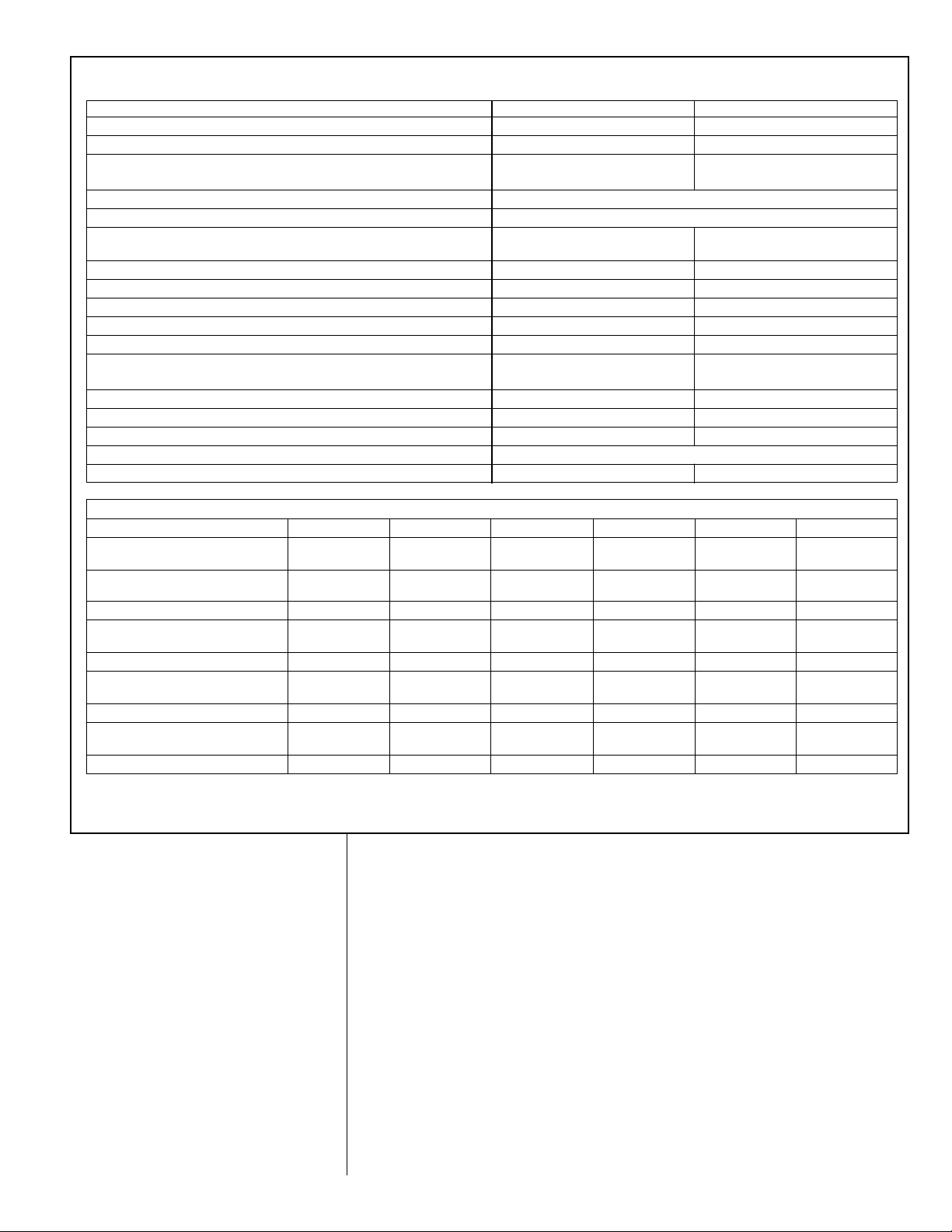
TABLE 2
HYSICAL AND ELECTRICAL DATA TABLE (RSG)
P
Condensing Unit 078 090
Operating Weight (lbs.) [kg] 264 [119.8] 287 [130.2]
Shipping Weight (lbs.) [kg] 283 [128.9] 306 [138.8]
COMPRESSOR:
Quantity 11
Type Scroll
RPM 3500
CONDENSER FANS:
Quantity 11
CFM [L/s] 4700 [2218] 4700 [2218]
Diameter (in.) [mm] 24 [610] 24 [610]
Motor Horsepower (ea.) [W]
Type PSC PSC
RPM 1075 1075
CONDENSER COIL:
Quantity 11
Rows 11⁄2 2
Fins per Inch 20 22
Square Feet [m2] 22.2 [3] 22.2 [3]
Fins/Tubes Aluminum/Copper
Tube Size, O.D. (in.) [mm]
ELECTRICAL DATA TABLE (RSG)
MODEL NO. RSG 078A3 078A4 078A5 090A3 090A4 090A5
COMPRESSOR MOTOR:
Electrical Characteristics 208/230-3-60 460-3-60 575-3-60 208/230-3-60 460-3-60 575-3-60
OPERATING CURRENT:
Rated Load Amps 22.4/22.4 10.6 7.0 25/25 12.2 9.0
Locked Rotor Amps 149 75 54 164 100 78
CONDENSER FAN MOTORS:
Volts & Phase 208/230-1 460-1 575-1 208/230-1 460-1 575-1
Full Load Amps (each) 2.2 1.3 1.0 2.2 1.3 1.0
SYSTEM CHARACTERISTICS:
Unit FLA 25.0 12 8.0 28.0 14.0 10.0
Minimum Circuit Ampacity 31/31 15 11.0 34/34 17 13
Max. Fuse Size or HACR
Circuit Breaker Ampacity 50/50 25 15 50/50 25 20
Disconnect Size 60 30 30 60 30 30
1
⁄3 [249]
3
⁄8 [10]
1
⁄3 [249]
3
⁄8 [10]
NOTE: N.E.C., C.E.C. and local codes take precedence over suggested wire and fuse sizes.
[ ] Designates Metric Conversion
VII. INSTALLATION
A. IMPORTANT MESSAGE TO OWNER
The manufacturer assumes no responsibility for equipment installed in violation of any
code or regulation. The operation portion of this manual gives instructions as to the service and care of the unit. It is recommended that the installer go over the operational
portion of this manual with the owner so that there is a full understanding of the equipment and how it is intended to function.
These instructions should be read and kept for future reference. It is suggested that this
booklet be affixed to or adjacent to the indoor equipment. It is addressed to your dealer
and serviceman, but we highly recommend that you read it—paying particular attention
to the section titled “MAINTENANCE.”
B. INSPECTION AND HANDLING
Inspect exterior of unit for evidence of rough handling in shipment. If damage is found,
enter claim at once. Unpack carefully after moving unit to approximate location. Any
damage should be reported immediately to the transportation company.
Material in this shipment was inspected at the factory and released to the common carrier with no known damage.
7
Page 8
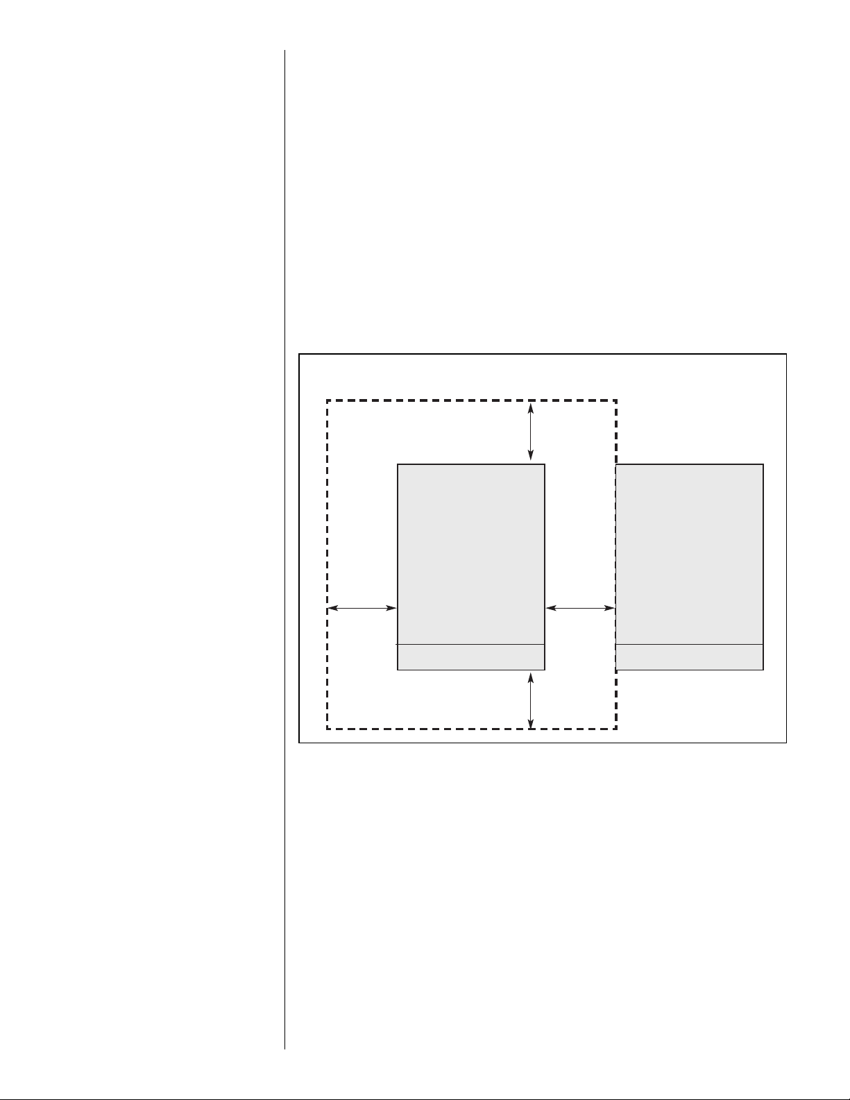
C. ORDER PARTS
Condensing Unit
Control Box End Control Box End
36” min. [914 mm]
36” min. [914 mm]
24” min.
[610 mm]
24” min.
[610 mm]
Condensing Unit
When reporting shortages or damaged parts, or when ordering repair parts, give the
omplete unit model and serial numbers which are stamped on the Unit Rating Plate.
c
D. STANDARD ITEMS
The condensing unit consists of a completely assembled package which includes a com-
ressor, a condenser coil, fan, fan motors, outdoor control box, factory wiring, factory
p
tubing and fittings.
E. INSTALLATION GENERAL
NOTE: These units must be installed outdoors. No ductwork can be attached, or
other modifications made, to the discharge grille. Modifications will affect performance or operation.
The condensing unit should be installed outdoors. It should be located as near as possible to the evaporator section to keep connecting refrigerant tubing lengths to a minimum.
The unit must be installed to allow a free air flow to the condenser coils.
If several units are installed adjacent to each other, care must be taken to avoid recirculation of air from one condenser to another. In all installations, adequate space must be
provided for installation and servicing.
FIGURE 3
LEARANCES
C
8
The unit must not be connected to any duct work. Do not locate unit under a roof drip; if
necessary, install gutters, etc., to prevent water run-off from hitting the unit. To prevent
air recirculation, it is recommended that the unit not be installed under an overhang, but
if necessary allow a minimum of 60 inches above the unit for air discharge.
NOTE: To prevent the possibility of freeze damage, you can install an air proving switch
in the air handler supply duct wired in series with the compressor contactor coil (24V)
which would lock out the compressor in the event of air flow failure.
F. ROOFTOP INSTALLATION (REFER TO FIGURE 4)
If rooftop installation is required, make certain that the building construction is adequate
for the weight of the unit. (Refer to physical data chart.) Before placing the unit on the
roof, make certain that the nylon rigging slings are of sufficient length to maintain equilibrium of the unit when lifting. Under no circumstances should the unit be lifted by only one
corner for rooftop installation.
G. SLAB INSTALLATION
Condensing units should be set on a solid level foundation. When installed at ground
level, the unit should be placed on a 6 inch cement slab. If the pad is formed at the
installation site, do not pour the pad tight against the structure, otherwise vibration will
be transmitted from the unit through the pad.
Page 9

FIGURE 4
ROOFTOP INSTALLATION
SPREADER BARS
NYLON SLINGS
VIII. REFRIGERANT PIPING DATA
CONDENSING UNITS ARE SHIPPED WITH A NITROGEN HOLDING CHARGE.
EVACUATE CONDENSING UNIT BEFORE CHARGING WITH REFRIGERANT.
TABLE 3
REFRIGERANT PIPING DATA
Equivalent Length (ft.) [m] of straight type “L” tubing for non-ferrous valves and fittings (brazed).
Tube Size,
O.D.
1/2 70 [21.3] 8.3 [2.5] 1.6 [0.5] 1.0 [0.3] 1.0 [0.3] 3.1 [0.9]
5/8 72 [21.9] 10.4 [3.2] 1.9 [0.6] 1.2 [0.4] 1.2 [0.4] 3.6 [1.1]
3/4 75 [22.9] 12.5 [3.8] 2.1 [0.7] 1.4 [0.4] 1.4 [0.4] 4.2 [1.3]
7/8 78 [23.8] 14.6 [4.4] 2.4 [0.7] 1.6 [0.5] 1.6 [0.5] 4.8 [1.5]
1 1/8 18.8 [5.7] 3.0 [0.9] 2.0 [0.6] 2.0 [0.6] 6.0 [1.8]
1 3/8 22.9 [7.0] 3.6 [1.1] 2.4 [0.7] 2.4 [0.7] 7.2 [2.2]
1 5/8 27.1 [8.3] 4.2 [1.3] 2.8 [0.8] 2.8 [0.8] 8.4 [2.6]
2 1/8 35.4 [10.8] 5.3 [1.6] 3.5 [1.1] 3.5 [1.1] 10.7 [3.3]
Solenoid
Valve
Angle
Valve
Short Radius
Ell
Long Radius
Ell
Tee,
Line flow
Tee,
Branch Flow
9
Page 10

WARNING
!
DO NOT USE OXYGEN TO PURGE LINES OR PRESSURE SYSTEM FOR
LEAK TEST. OXYGEN REACTS VIOLENTLY WITH O IL, WHICH CAN
CAUSE AN EXPLOSION RESULTING IN SEVERE PERSONAL INJURY OR
DEATH.
FIGURE 5
IQUID LINE PRESSURE DROP PER 100 FEET EQUIVALENT LENGTH
L
(TYPE L COPPER TUBING)
NOTES:
1. When evaporator coil is above condenser, the pressure drop due to vertical lift (.5
PSIG per foot of lift) must be added to the pressure drop derived from this curve.
2. Size liquid line for no more than 10°F loss (approximately 50 PSIG total pressure
drop).
3. Do not oversize liquid line. Oversized liquid lines add significantly to the amount of
refrigerant required to charge the system.
4. The maximum recommended velocity with solenoid valves or other quick closing
devices in the liquid line is 300 FPM.
A. INSTALLATION OF PIPING
Once located, the condensing unit is ready to be interconnected with the evaporator
using ONLY refrigeration grade dehydrated tubing. The following should be considered
when connecting the tubing.
1
1. Pitch the suction line toward the compressor approximately
facilitate oil return.
2. It is recommended that the sight glass, filter drier and liquid line solenoid valve be
installed in the liquid line just prior to the evaporator.
3. Silver solder (such as silfos, Easy Flow, etc.) should be used for all refrigerant joints.
4. Thoroughly clean all joints before fluxing. DO NOT USE ACID FLUX.
5. When fluxing, limit the application of paste to the minimum and always apply flux to
the male portion of the connection.
6. Suction lines should be insulated to prevent condensate drip. Use insulation of at
3
⁄8 inch wall thickness. The insulation should be installed on the tubing prior to
least
making the sweat connections.
⁄2 inch every 10 feet to
10
Page 11

7. Insulate the liquid line whenever the heat pick-up or transfer can affect the sub-cooling.
8. Care should be taken to avoid transmission of noise or vibration to building structure.
FIGURE 6
UCTION LINE SYSTEM CAPACITY LOSS IN PERCENT PER 100 FEET EQUIVALENT LENGTH
S
TYPE L COPPER TUBING)
(
NOTES:
1. The minimum velocity line (700 fpm) is recommended for cooling only units with vertical or horizontal run refrigerant lines.
2. For suction pressure drop (PSIG), multiply percent (%) loss by 1.18.
B. TYPICAL PIPING RECOMMENDATIONS
REFRIGERANT PIPING:
The following will be of help in accomplishing a successful installation.
1. Size liquid line for no more than 10°F loss which corresponds to approximately 50
PSIG pressure drop.
2. Size suction lines for no more than 2°F loss which corresponds to approximately 5
PSIG pressure drop.
3. Install sight glass, filter drier and solenoid valve in liquid line adjacent to evaporator.
Filter drier should be between the condensing unit and sight glass.
1
4. Pitch all horizontal suction lines downward in the direction of flow. (
⁄2" to 10 ft. run)
11
Page 12
5. When making up refrigerant piping, take every precaution to prevent dirt and moisture
from entering the piping.
6. Locate the condensing unit and evaporator(s) as close together as possible to minimize piping runs.
7. Liquid or suction lifts not to exceed 60 ft.
TABLE 4
ECOMMENDED VAPOR AND LIQUID LINE SIZES FOR VARIOUS
R
LENGTHS OF RUN
RECOMMENDED VAPOR AND LIQUID LINE
SIZES FOR VARIOUS LENGTHS OF RUN
EQUIVALENT
LENGTH TO
EVAPORATOR
(FEET)
0' to 15'
16' to 50'
51' to 100'
101' to 150'
LIQUID LINE O.D.
SIZES (INCHES)
078
1
1
1
1
⁄2
⁄2
⁄2
⁄2
090
1
1
1
1
⁄2
⁄2
⁄2
⁄2
VAPOR LINE O.D.
SIZES (INCHES)
078 090
11⁄8 11⁄8
11⁄8 11⁄8
11⁄8 13⁄8
13⁄8 13⁄8
NOTE: Runs between condenser and evaporator not to
exceed 150' linear equivalent length.
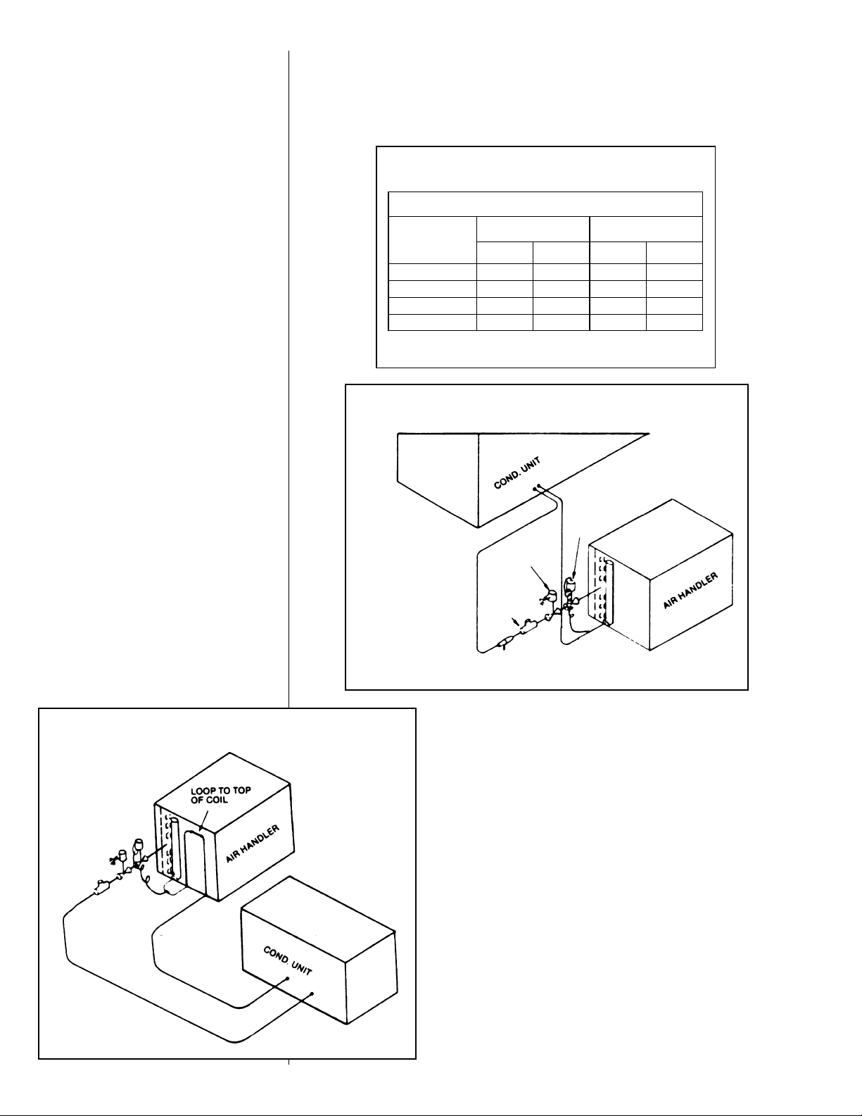
FIGURE 7
COIL BELOW CONDENSING UNIT
FIGURE 8
COIL ABOVE CONDENSING UNIT
LIQUID
LINE
SUCTION
LINE
LIQUID
LINE
NOTE: PIPING
ACCESSORIES SHOWN
SHOULD BE MOUNTED
AS CLOSE TO AIR
HANDLER UNIT AS
POSSIBLE
SOLENOID
VALVE
SIGHT GLASS
TX VALVE
SUCTION
LINE
12
Page 13
VIX. WIRING
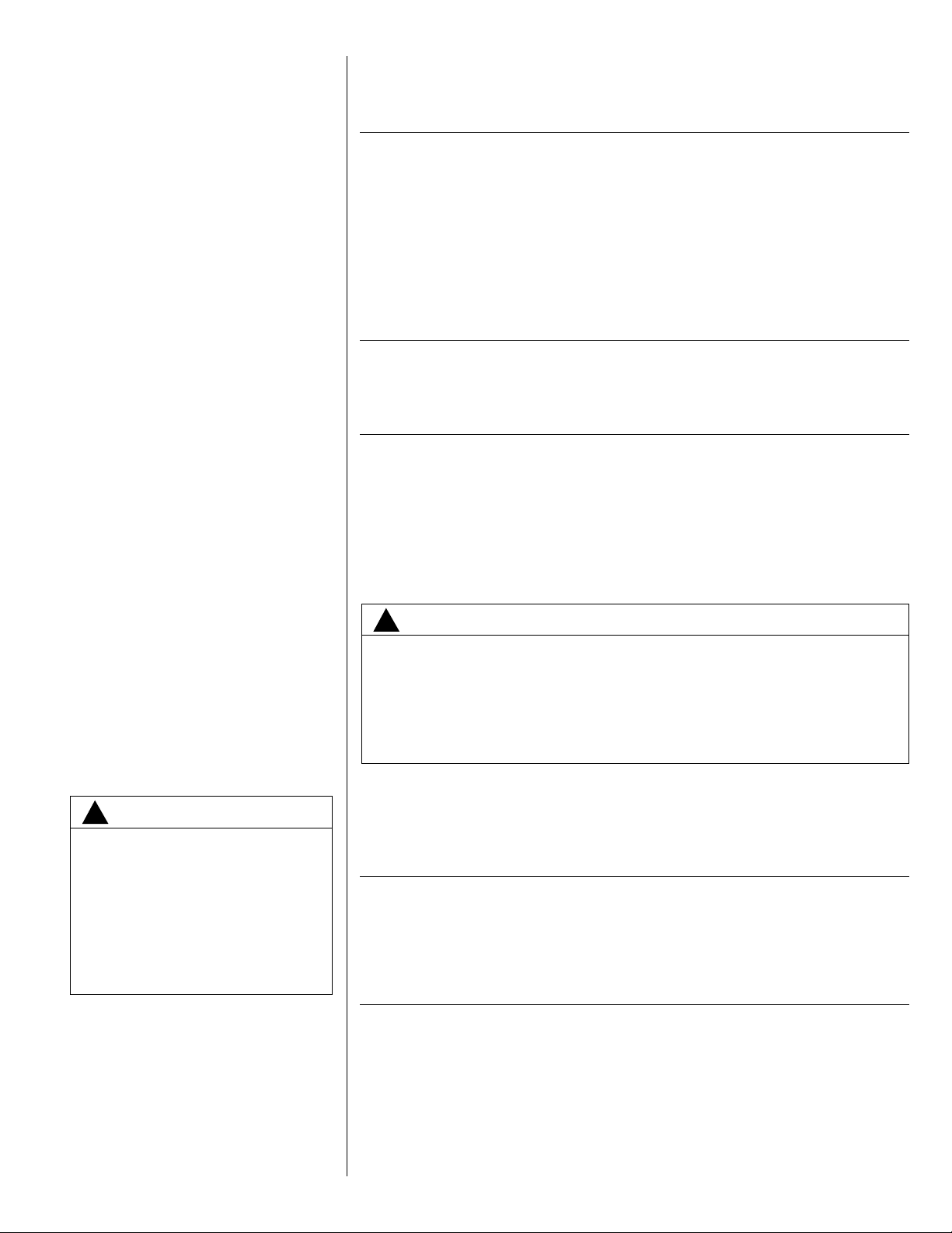
NOTE: Field wiring must comply with the National Electric Code (CEC in Canada) and
any local ordinance that may apply.
X. ELECTRICAL POWER
It is important that proper electrical power is available at the unit. Voltage must not vary
more than 10% of that stamped on the rating plate. (See Electrical Data Table for minimum and maximum voltage.) Interphase voltage variation on three-phase units must not
be more than 3%. Contact local power company for correction of improper voltage or
phase unbalance.
IMPORTANT: Models equipped with scroll compressors must be phased correctly for
proper compressor rotation. If the compressor is noisy or if suction and discharge pressures do not appear normal, reverse any two power leads to the unit. Extended run time in
reverse rotation will damage the compressor and lead to premature failure.
XI. POWER WIRING
Power wiring must be run in grounded rain-tight conduit. Power wiring must comply with
the National Electric Code (C.E.C. in Canada) and any applicable local code.
XII. WIRE ROUTING
POWER WIRING MUST BE RUN IN CONDUIT. Conduit must be run through the connector panel below the service cover and attached to the bottom of the control box.
If low (extra-low in Canada) voltage control wire is run in conduit with power supply,
Class I insulation is required. If run separate, Class II is required. Low voltage wiring
may be run through the insulated bushing provided in the 7/8 " hole in the connector
panel then routed to the control box.
WARNING
!
THI S UNI T MUS T BE PE RMA NENTLY GROUNDED. A GROUND
LUG IS PROVI DED NE AR THE
CONTACT OR FOR A GRO UN D
WIRE. FAILURE TO DO SO CAN
CAUSE A FIRE OR ELECTRICAL
SHOCK RESULTING IN PROPERTY DAMAGE, SEVERE PERSONAL INJURY OR DEATH.
WARNING
!
AFTER COMPLETION OF WIRING CHECK ALL ELECTRICAL CONNECTIONS, INCLUDING FACTORY WIRING WITHIN THE UNIT, AND MAKE
SURE ALL CONNECTIONS ARE TIGHT, REPLACE AND SECURE ALL
ELECTRICAL BOX COVERS AND ACCESS DOORS BEFORE LEAVING
UNIT OR TURNING ON POWER TO CIRCUIT SUPPLY UNIT. FAILURE TO
DO SO CAN CAUSE A FIRE OR ELECTRICAL SHOCK RESULTING IN
PROPERTY DAMAGE, PERSONAL INJURY OR DEATH.
XIII. GROUNDING
A grounding lug is provided in control box for a ground wire.
Grounding may be accomplished by grounding the power line conduit to the unit.
XIV. THERMOSTAT — 61⁄2 AND 71⁄2 TON
A single-stage cooling, two-stage heating (if heating is used) thermostat should be
mounted on an inside wall about four to five feet above the floor in a location where it will
not be affected by the sun or drafts, from open doors or other sources. Install, level, and
after installation check the thermostat calibration and recalibrate if necessary.
XV. LEAK TESTING
Pressure line set and coil through service fittings with dry nitrogen to 150 psig maximum.
Leak test all joints using liquid detergent. If a leak is found, relieve pressure, repair and
retest.
13
Page 14

XVI. R-410A REFRIGERANT
A. TOOLS REQUIRED FOR INSTALLING & SERVICING R-410A MODELS
anifold Sets:
M
-Up to 800 PSIG High Side
-Up to 250 PSIG Low Side
-550 PSIG Low Side Retard
Manifold Hoses:
-Service Pressure Rating of 800 PSIG
Recovery Cylinders:
400 PSIG Pressure Rating
-
-Dept. of Transportation 4BA400 or 4BW400
!
CAUTION
R-410A systems operate at higher pressures than R-22 systems. Do not use
R-22 service equipment or components on R-410A equipment.
B. SPECIFICATION OF R-410A:
Application: R-410A is not a drop-in replacement for R-22; equipment designs must
accommodate its higher pressures It cannot be retrofitted into R-22 condensing units.
Physical Properties: R-410A has an atmospheric boiling point of -62.9°F and its saturation pressure at 77°F is 224.5 psig.
Composition: R-410A is an azeotropic mixture of 50% by weight difluoromethane
(HFC-32) and 50% by weight pentafluoroethane (HFC-125).
Pressure:
Recovery and recycle equipment, pumps, hoses and the like need to have design pressure ratings appropriate for R-410A. Manifold sets need to range up to 800 psig high-
side and 250 psig low-side with a 550 psig low-side retard. Hoses need to have a service pressure rating of 800 psig. Recovery cylinders need to have a 400 psig service
pressure rating. DOT 4BA400 or DOT 4BW400.
Combustibility: At pressures above 1 atmosphere, mixture of R-410A and air can
become combustible. R-410A and air should never be mixed in tanks or supply
lines, or be allowed to accumulate in storage tanks. Leak checking should never
be done with a mixture of R-410A and air. Leak checking can be performed safely
with nitrogen or a mixture of R-410A and nitrogen.
The pressure of R-410A is approximately 60% (1.6 times) greater than R-22.
C. QUICK REFERENCE GUIDE FOR R-410A
• R-410A refrigerant operates at approximately 60% higher pressure (1.6 times) than
R-22. Ensure that servicing equipment is designed to operate with R-410A.
• R-410A refrigerant cylinders are pink in color.
• R-410A, as with other HFC’s, is only compatible with POE oils.
• Vacuum pumps will not remove moisture from oil.
• R-410A systems are to be charged with liquid refrigerants. Prior to March 1999,
R-410A refrigerant cylinders had a dip tube. These cylinders should be kept upright for
equipment charging. Post March 1999 cylinders do not have a dip tube and should be
inverted to ensure liquid charging of the equipment.
• Do not install a suction line filter drier in the liquid line.
• A liquid line filter drier is standard with every unit. Only manufacturer approved liquid
line filter driers can be used. These filter driers are rated for minimum working pressure of 600 psig.
• Desiccant (drying agent) must be compatible for POE oils and R-410A.
14
Page 15
D. REPLACEMENT UNITS
To prevent failure of a new condensing unit, the existing evaporator tubing system must
be correctly sized and cleaned or replaced. Care must be exercised that the expansion
device is not plugged. For new and replacement units, a liquid line filter drier should be
installed and refrigerant tubing should be properly sized. Test the oil for acid. If positive,
a suction line filter drier is mandatory.
IMPORTANT: WHEN REPLACING AN R-22 UNIT WITH AN R-410A UNIT, EITHER
REPLACE THE LINE SET OR ENSURE THAT THE EXISTING LINE SET IS THOROUGHLY CLEANED OF ANY OLD OIL OR DEBRIS.
CAUTION
!
Only use evaporators approved for use on R-410A systems. Use of existing R-22
evaporators can introduce mineral oil to the R-410A refrigerant forming two different liquids and decreasing oil return to the compressor. This can result in compressor failure.
E. EVAPORATOR COIL
REFER TO EVAPORATOR COIL MANUFACTURER’S INSTALLATION INSTRUCTIONS:
IMPORTANT: The manufacturer is not responsible for the performance and operation of
a mismatched system, or for a match listed with another manufacturer’s coil.
XVII. EVACUATION AND CHARGING
The evacuation of any system component that has been exposed to atmosphere or lost
its charge is essential before charging. Never attempt to operate a system while it is
under a vacuum.
FIGURE 9
TYPICAL FIELD WIRING CONNECTIONS — 61⁄2 AND 71⁄2 TON
15
Page 16
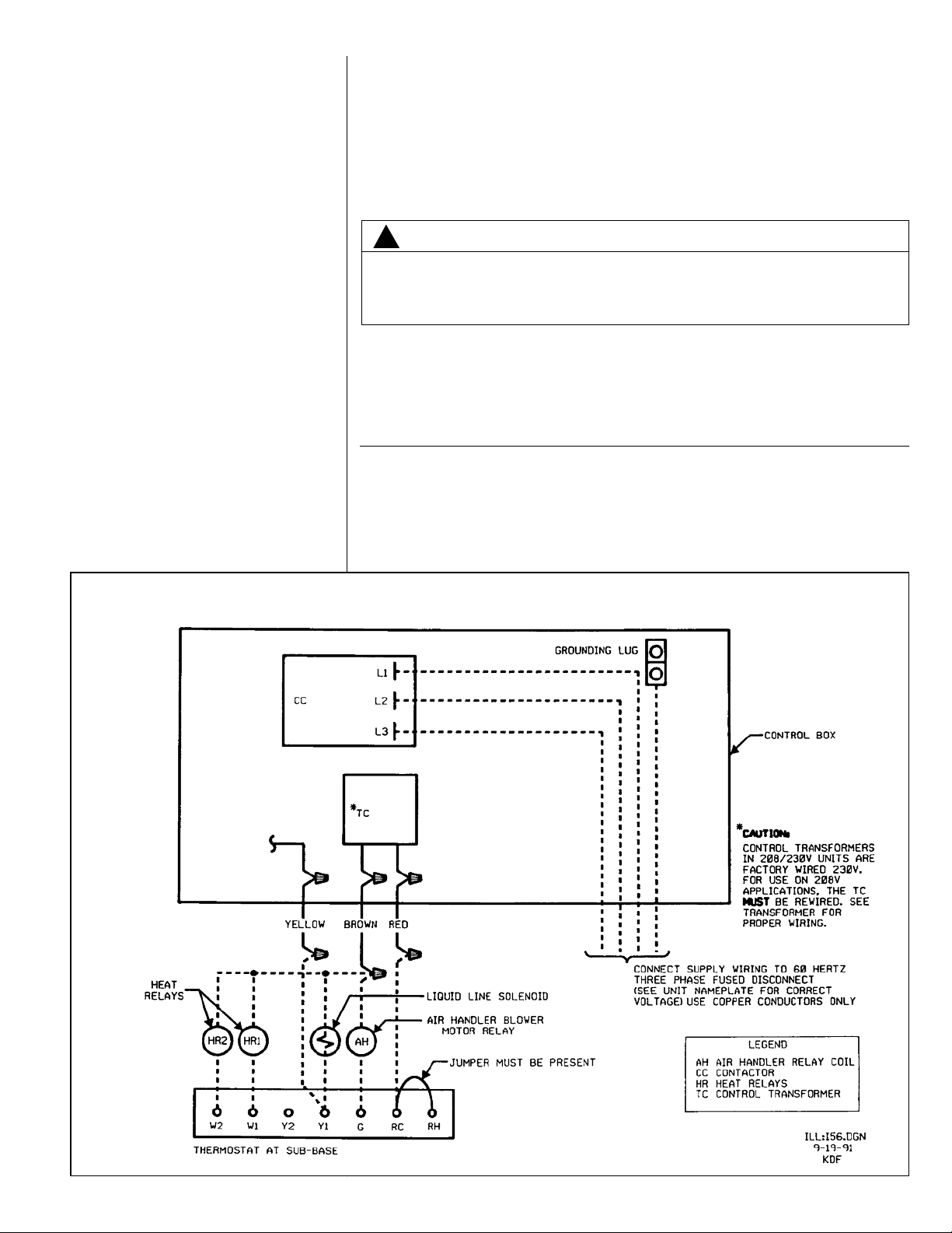
ABLE 5
T
FIELD WIRE SIZE FOR 24 VOLT THERMOSTAT CIRCUITS
SOLID COPPER WIRE - AWG
3.0 16 14 12 10 10 10
2.5 16 14 12 12 10 10
2.0 18 16 14 12 12 10
Thermostat
Load - Amps
(1) Wire length equals twice the run distance.
50 100 150 200 250 300
Length of Run - Feet (1)
OTE: The condensing unit is shipped with a holding charge of dry nitrogen
N
which must be purged from the unit before evacuation.
1. Since the condensing unit itself must be evacuated, open the suction, discharge and
iquid shut-off valves.
l
2. Use a refrigeration type vacuum pump capable of evacuation in the 500 micron
range.
3. Connect the vacuum pump to the service manifold assembly with a pressure gauge
that will read 30 inches vacuum. Connect the service manifold to the suction line
schrader valve port.
1
4. With an accurate scale,
⁄2 oz., set refrigerant tank up so its weight can be measured
while in a position to charge liquid. (Unit must be off.) Energize liquid line solenoid
valve by wiring valve to 24V power supply (or open by manual stem if applicable).
5. Connect to the liquid shut-off valve port. Shut off tank and evacuate the system. The
pressure gauge should read at least 29.5" of vacuum.
6. Triple evacuate the system.
7. The refrigerant system will now be free of noncondensables.
8. Remove vacuum pump from 3-way valve.
9. Before tightening, purge tank and service valve hose.
CHARGING HINTS
SYMPTOM
High head pressure a. Air flow to or from condenser restricted or a. Remove obstruction, relocate condensing unit,
dirty condenser if necessary clean condenser.
b. Faulty condenser fan or motor. b. Replace.
c. Overcharge of refrigerant c. Reduce charge.
d. Air in system. d. Evacuate and recharge.
Low head pressure a. Short of refrigerant. a. Check for leak, add charge.
b. Low evaporator air flow. b. Increase blower speed, check filters.
Low vapor & a. Short of refrigerant. a. Check for leak—add refrigerant.
hot compressor
Excessive sweating a. Low indoor airflow a. Increase speed of air handler blower or reduce
b. Excess refrigerant b. Slowly reduce charge.
POSSIBLE CAUSE REMEDY
restriction—replace air filter.
16
10. Note weight of refrigerant tank.
11. De-energize liquid line solenoid valve. Open refrigerant tank valve. Allow pressure in
tank and unit to equalize.
12. Close off service valve to liquid port and note weight of refrigerant tank.
13. Re-wire liquid line solenoid to thermostat control. Close main disconnect switch and
turn thermostat to lowest setting.
14. Charge unit per chart.
Page 17
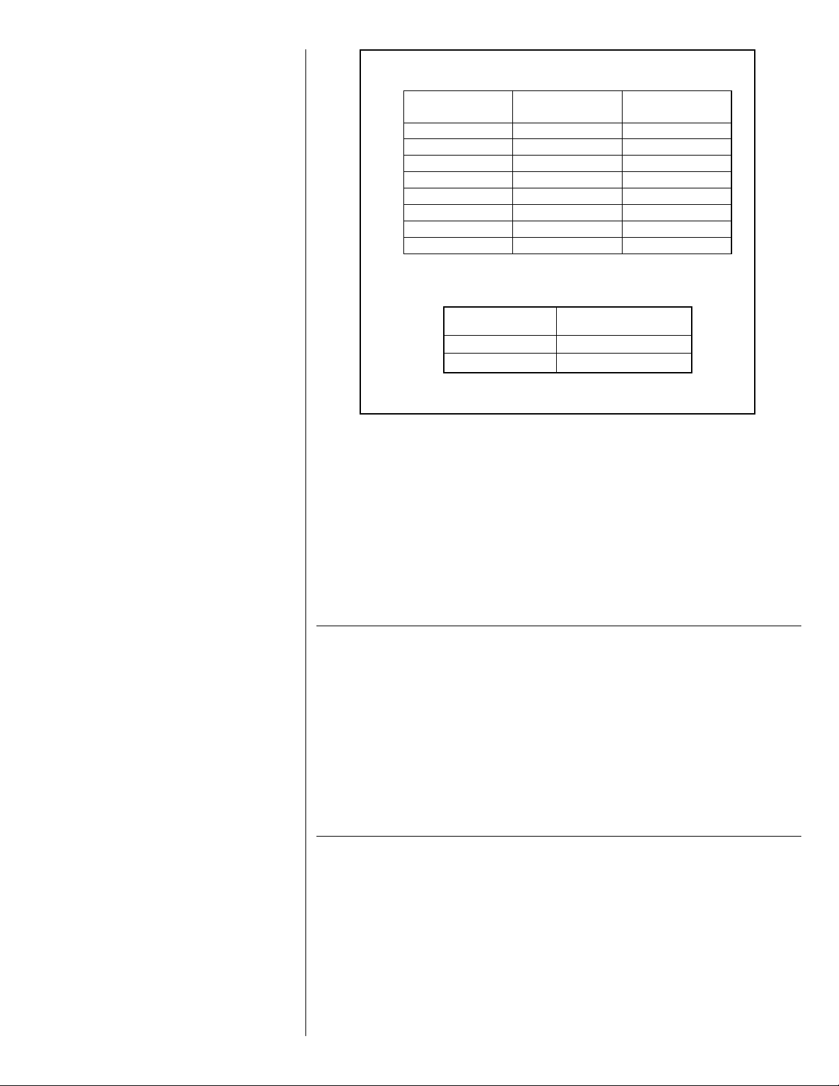
TABLE 6
EQUIRED OZS. R-410A PER FT. OF TUBING
R
Tube Size
O.D., In.
1/2 1.06 0.04
5/8 1.65 0.07
3/4 2.46 0.10
7/8 3.28 0.13
1 1/8 0.22
1 3/8 0.34
1 5/8 0.48
2 1/8 0.84
Quantities based on 110°F liquid and 45°F vapor.
BASIC SYSTEM CHARGE*
Unit
Model
RSG078 178 [5046]
RSG090 242 [6861]
*-System with 0 Feet [0] of tubing.
15. Note weight of refrigerant tank.
16. When system has stabilized, check superheat at the suction line service valve. The
actual line temperature should be 15° to 25°F higher than the saturation temperature
corresponding to the suction pressure. If superheat is measured at evaporator, the
actual line temperature should be 15° to 20° higher than the saturation temperature
corresponding to the suction pressure.
17. Close service ports on suction and liquid valves. Remove service gauges.
18. Replace service port caps and valve stem caps. These caps must be replaced to
prevent leaks.
19. Record total charge quantity on rating plate.
Liquid
oz/ft
Basic System
Charge, Oz. [g] *
Vapor
oz/ft
XVIII. SEQUENCE OF OPERATION — 61⁄2
XVIII. AND 71⁄2 TON
1. When the room temperature is higher than the thermostat setting, the thermostat con-
tacts close and energize the compressor contactor (CC) through the high pressure,
and low pressure controls. If the unit has “short cycled” and the optional anti-short
cycle timer (TDC) has been supplied, the contactor coil (CC) will remain de-energized
for up to five (5) minutes.
2. The system will continue cooling operation, as long as the contacts of all safety
devices are closed and until the thermostat is satisfied.
3. When the thermostat is satisfied, compressor or contactor (CC) is de-energized.
XIX. ACCESSORIES
A. ANTI-SHORT CYCLE TIMER
ANTI-SHORT-CYCLE TIMER — Prevents restarting of unit for five minutes if shut down
for any reason. (See wiring diagram and schematic in this manual for proper location
and installation; item TDC.)
17
Page 18

FIGURE 10
NTI-SHORT CYCLE TIMER
A
B. LIQUID PRESSURE CONTROL
Outdoor fan motor speed control designed to regulate condenser head pressure at low
ambients by varying the air volume through the condenser. Has been tested and is available through the parts department.
FIGURE 11
LIQUID LINE SOLENOID VALVE
C. LIQUID LINE SOLENOID VALVE
LIQUID LINE SOLENOID VALVE (24V) — Recommended for all split system applications, to prevent refrigerant migration during off cycles. See wiring connection (See
Figure 11). Solenoid to be located in liquid line close to air handler.
18
D. SIGHT GLASS / MOISTURE INDICATOR
SIGHT GLASS — Allows viewing of the refrigerant. Bubbles may indicate a shortage of
refrigerant or a restriction in the liquid line. The color indicator shows relative moisture
saturation of the refrigerant. Its inclusion in the refrigerant piping is recommended. A
minimum of 12 hours after installation is required before attempting to determine if a
moisture condition within the system exists.
Page 19

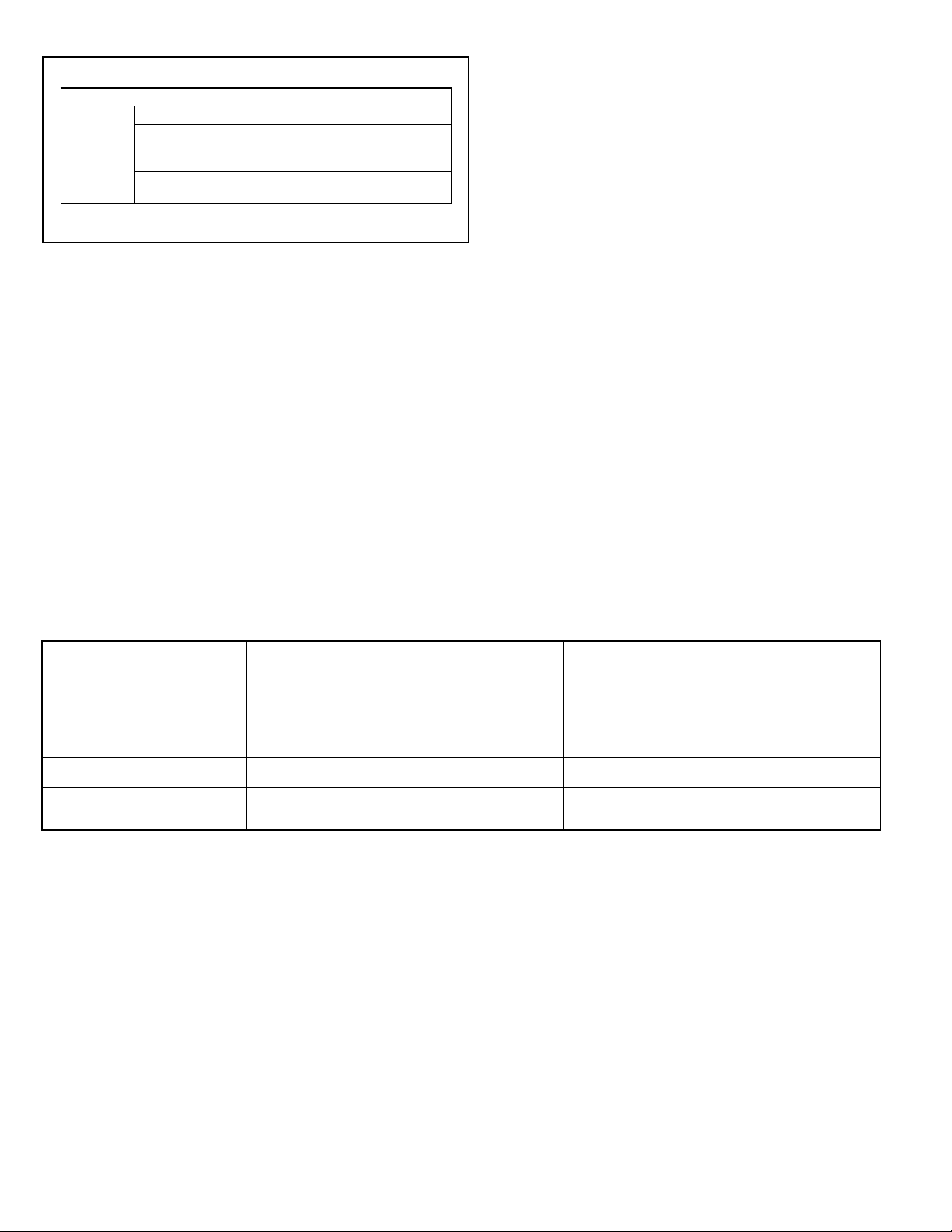
Pressure at Liquid Service Port (psig)
Pressure at Suction Service Port (psig)
6-1/2 TON CONDENSING UNIT 60HZ.
REFRIGERANT R-410A
92-102644-01-01
CAUTION: BEFORE FINAL REFRIGERANT CHECK, INDOOR AIR TEMPERATURE SHOULD BE AT COMFORT CONDITIONS
FOR MOST ACCURATE RESULTS.
INSTRUCTIONS:
1. CONNECT PRESSURE GUAGES TO SUCTION AND LIQUID PORTS ON UNIT.
2. MEASURE AIR TEMPERATURE TO OUTDOOR COIL.
3. PLACE AN "X" ON THE APPROPRIATE CHART WHERE THE SUCTION AND LIQUID PRESSURES CROSS.
4. IF "X" IS BELOW AMBIENT TEMPERATURE LINE, ADD CHARGE AND REPEAT STEP 3.
5. IF "X" IS ABOVE AMBIENT TEMPERATURE LINE, RECOVER EXCESS CHARGE AND REPEAT STEP 3.
6. IF CONDENSER FANS ARE NOT RUNNING, THE HEAD PRESSURE CONTROL MAY REQUIRE JUMPERING.
REQ UIR ED O UNC ES R -41 0A
CHA RGE PE R F OOT O F TU BIN G
TUBE S IZE
O.D. IN.
LIQUID
LINE
VAPOR
LINE
1/2
5/8
1-1/ 8
1-3/ 8
1.06
1.65
.22
.34
REFRIGERANT REQUIRED: 178 OZ. WITH 0 FT. OF SUCTION AND LIQUID LINE.
115
110
105
100
95
90
85
80
75
70
65
60
55
175
200
225
250
275
300
325
350
375
400
425
450
475
500
525
100 105 110 115 120 125 130 135 140 145 150 155 160 165
XX. MISCELLANEOUS
A. CHARGE CHARTS
FIGURE 12
RSG078
SYSTEM CHARGE CHART
61⁄2 TON CONDENSER
19
Page 20

Pressure at Liquid Service Port (psig)
Pressure at Suction Service Port (psig)
Outdoor Ambient (F° DB)
7-1/2 TON CONDENSING UNIT 60HZ.
R
EFRIGERANT R-410A
92-102644-03-01
CAUTION: BEFORE FINAL REFRIGERANT CHECK, INDOOR AIR TEMPERATURE SHOULD BE AT COMFORT CONDITIONS
FOR MOST ACCURATE RESULTS.
INSTRUCTIONS:
1. CONNECT PRESSURE GUAGES TO SUCTION AND LIQUID PORTS ON UNIT.
2. MEASURE AIR TEMPERATURE TO OUTDOOR COIL.
3. PLACE AN "X" ON THE APPROPRIATE CHART WHERE THE SUCTION AND LIQUID PRESSURES CROSS.
4. IF "X" IS BELOW AMBIENT TEMPERATURE LINE, ADD CHARGE AND REPEAT STEP 3.
5. IF "X" IS ABOVE AMBIENT TEMPERATURE LINE, RECOVER EXCESS CHARGE AND REPEAT STEP 3.
6. IF CONDENSER FANS ARE NOT RUNNING, THE HEAD PRESSURE CONTROL MAY REQUIRE JUMPERING.
REQ UIR ED O UNC ES R -41 0A
CHA RGE PE R F OOT OF T UBI NG
TUBE S IZE
O.D. IN.
LIQUID
LINE
VAPOR
LINE
1/2
5/8
1-1 /8
1-3 /8
1.0 6
1.6 5
.22
.34
REFRIGERANT REQUIRED: 239 OZ. WITH 0 FT. OF SUCTION AND LIQUID LINE
115
110
105
100
95
90
85
80
75
70
65
60
55
175
200
225
250
275
300
325
350
375
400
425
450
475
500
525
100 105 110 115 120 125 130 135 140 145 150 155 160 165
FIGURE 13
RSG090
SYSTEM CHARGE CHART
71⁄2 TON CONDENSER WITH 10 TON EVAPORATOR
20
Page 21

B. MAINTENANCE AND OPERATION
1. All access panels must be in place when unit is in operation.
2. For maximum efficiency, the condenser coil must be kept clean. Periodic inspections,
depending on local conditions are recommended. If it is necessary to clean the condenser coil, use a common garden hose.
3. Never operate the unit without filters installed in the air handler.
4. If a compressor crankcase heater is used, it must be turned on 12 hours prior to start-
ng the compressor.
i
1. CONTACTOR
The contactor is an electrical switch which operates the compressor and condenser
fans. Its 24 volt coil is activated either directly or indirectly by the room thermostat.
2. HIGH PRESSURE SWITCH (HPC)
Opens the contactor (24 volt) circuit on high refrigerant pressure—Manual Reset—check
for cause of tripping before putting unit back in service.
3. LOW PRESSURE SWITCH (LPC)
Acts as safety against loss of refrigerant and low evaporator temperatures.
4. PRE-START CHECK
PRE-START CHECK
1. Is condensing unit properly located and level?
2. Is air free to travel to and from condensing unit?
3. Is the wiring correct and according to the unit wiring diagram?
4. Are wiring connections tight? (Including those in unit and
compressor electrical box.)
5. Is the unit properly grounded?
6. Is circulating air blower correctly wired?
7. Is condensing unit properly fused?
8. Is the thermostat level, correctly wired and in a good location?
9. Is the ductwork correctly sized, run, taped and insulated?
10. Is refrigerant tubing neatly run and suction line thoroughly
insulated?
11. Is condensate drain line properly sized, run, trapped and
pitched?
12. Are refrigerant connections tight and leak tested?
13. Is filter clean and in place?
14. Does the condenser fan turn free without rubbing?
15. Is the fan tight on the fan shaft?
16. Are all covers and access panels in place to prevent air
loss?
17. Are refrigerant valves open for full flow?
21
Page 22

C. TROUBLESHOOTING
!
WARNING
DISCONNECT ALL POWER TO UNIT BEFORE SERVICING. CONTACTOR MAY BREAK ONLY ONE SIDE. FAILURE
TO SHUT OFF POWER CAN CAUSE ELECTRICAL SHOCK RESULTING IN PERSONAL INJURY OR DEATH.
SYMPTOM POSSIBLE CAUSE REMEDY
Unit will not run • Power off or loose electrical connection • Check for correct voltage at compressor contactor in control box
Condenser fan runs, compressor • Run or start capacitor defective (single phase only) • Replace
doesn’t • Start relay defective (single phase only) • Replace
Insufficient cooling • Improperly sized unit • Recalculate load
Compressor short cycles • Incorrect voltage • At compressor terminals, voltage must be ±10% of
Registers sweat • Low evaporator airflow • Increase speed of blower or reduce restriction - replace air
High head-low vapor pressures • Restriction in liquid line, expansion device or filter drier • Remove or replace defective component
High head-high or normal vapor • Dirty condenser coil • Clean coil
pressure - Cooling mode • Refrigerant overcharge • Correct system charge
High head-high or normal vapor • Low air flow - condenser coil • Check filters - correct to speed
pressure - Heating mode • Refrigerant overcharge • Correct system charge
Low head-high vapor pressures • Defective Compressor valves • Replace compressor
Low vapor - cool compressor - • Low evaporator airflow • Increase speed of blower or reduce restriction - replace air filter
iced evaporator coil • Operating below 65°F outdoors • Add Low Ambient Kit
High vapor pressure • Excessive load • Recheck load calculation
Fluctuating head & vapor • TXV hunting • Check TXV bulb clamp - check air distribution on coil - replace
pressure TXV
Gurgle or pulsing noise at • Air or non-condensibles in system • Recover refrigerant, evacuate & recharge
expansion device or liquid line
• Thermostat out of calibration-set too high • Reset
• Defective contactor • Check for 24 volts at contactor coil - replace if contacts are
open
• Blown fuses • Replace fuses
• Transformer defective • Check wiring-replace transformer
• High pressure control open (if provided) • Reset-also see high head pressure remedy-The high pressure
control opens at 610 PSIG
• Interconnecting low voltage wiring damaged. • Replace thermostat wiring
• Loose connection • Check for correct voltage at compressor check & tighten all connections
• Compressor stuck, grounded or open motor winding, • Wait at least 2 hours for overload to reset.
open internal overload. If still open, replace the compressor.
At compressor terminals, voltage must be within 10% of rating
plate volts when unit is operating.
• Low voltage condition • Add start kit components
• Improper airflow • Check - should be approximately 400 CFM per ton.
• Incorrect refrigerant charge • Charge per procedure attached to unit service panel
• Air, non-condensibles or moisture in system • Recover refrigerant, evacuate & recharge, add filter drier
• Incorrect voltage • At compressor terminals, voltage must be within 10% of rating
plate volts when unit is operating.
nameplate marking when unit is operating.
• Defective overload protector • Replace - check for correct voltage
• Refrigerant undercharge • Add refrigerant
filter
• Flow check piston size too small • Change to correct size piston
• Incorrect capillary tubes • Change coil assembly
• TXV does not open • Replace TXV
• Outdoor fan not running • Repair or replace
• Air or non-condensibles in system • Recover refrigerant, evacuate & recharge
• Air or non-condensibles in system • Recover refrigerant, evacuate & recharge
• Dirty condenser coil • Check filter - clean coil
• Defective TXV(s) • Replace coil assembly
• Moisture in system • Recover refrigerant - evacuate & recharge - add filter drier
• Defective compressor • Replace
• Air or non-condensibles in system • Recover refrigerant, evacuate & recharge
22
Page 23

23
Page 24

24
CM 1208
 Loading...