

Page 1
INSTALLATION, OPERATION
& MAINTENANCE MANUAL
Portable Room Air Conditioner
and Heat Pump
PSH-141A
French version of this manual is available on our website
Heat Controller, Inc. • 1900 Wellworth Ave. • Jackson, MI 49203 • (517)787-2100 • www.heatcontroller.com
Page 2

Installation, Operation & Maintenance PSH-141A Heat Controller, Inc.
TABLE OF CONTENTS
SAFETY PRECAUTIONS
Safety rules.......................................................................................................................3
Operating conditions.........................................................................................................3
Electrical information ........................................................................................................4
IDENTIFICATION OF PARTS
Accessories ......................................................................................................................4
Identication of parts ........................................................................................................5
AIR CONDITIONER FEATURES
Electronic control operating instructions ...........................................................................6
OPERATING INSTRUCTIONS
Operating instructions.......................................................................................................8
INSTALLATION INSTRUCTIONS
Location ............................................................................................................................9
Window slider kit installation.............................................................................................9
Exhaust hose installation ................................................................................................12
Condensate drainage .....................................................................................................13
CARE AND MAINTENANCE
Care and maintenance ...................................................................................................14
TROUBLESHOOTING TIPS
Trouble shooting .............................................................................................................15
2
Page 3
Heat Controller, Inc. PSH-141A Installation, Operation & Maintenance
SAFETY PRECAUTIONS
Safety rules
To prevent injury to the user or other people and property damage, the following instructions must be
followed. Incorrect operation due to ignoring the instructions may cause harm or damage.
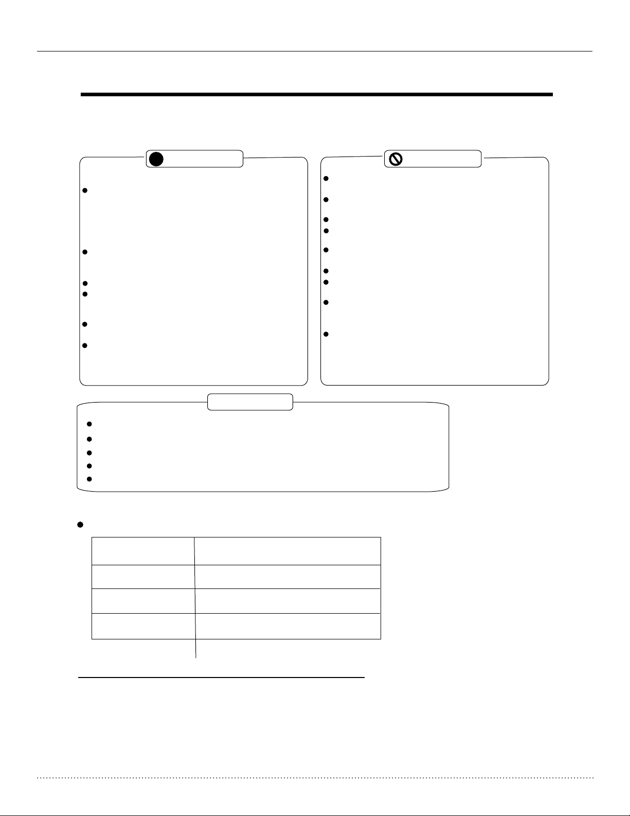
Always do this
!
Do not operate your air conditioner in a damp/
Your air conditioner should be used in such a way
that it is protected from moisture. e.g. condensation,
splashed water, etc. Do not place or store your air
conditioner where it can fall or be pulled into water
or any other liquid. Unplug immediately if water
enters unit.
Always transport use and store your air conditioner
in a vertical, upright position on a stable, level
surface.
Turn off the product when not in use.
Always contact a qualified to make
repairs. If the supply cord is damaged it must be
repaired by an authorized servicer.
Keep a clearance of at least 1 ft. (30cm) around
the unit, away from walls, furniture and curtains.
If the air conditioner is knocked over during use,
turn off the unit and unplug from the main power
supply immediately.
servicer
Save Energy
humid room such as a bathroom or laundry room.
Do not touch the unit with wet or damp hands or
to avoid electrical shock.
Do not remove any cover panels.
Never use this appliance if it is not working properly,
or if it has been dropped or damaged.
Never use the plug to start and stop the unit. Always
use the switch on the control panel.
Do not cover or obstruct the inlet or outlet grilles.
Do not use hazardous chemicals to clean or allow
them to come into contact with the unit.
Do not use the unit in the presence of inflammable
substances or vapors such as alcohol, insecticides,
gasoline, etc.
Do not use this product for functions other than
those described in this instruction manual.
Use the unit in the recommended room size - see carton.
Locate the unit where furniture or other objects cannot obstruct the air flow.
Keep blinds/curtains closed during the sunniest part of the day.
Keep the filters clean.
Keep doors and windows closed to keep cool air in and warm air out.
Never do this
Oper ating con ditions
The air conditioner must be operated within the temperature range indicated below:
MODE ROOM TEMPERATURE
O
COOL
DRY
HEAT
62-95 F (17-35OC)
O
55-95 F (13-35OC)
O
41-88 F (O5-30 C)
Suggested tools for window kit installation
1. Screwd river(me dium size Phillips)
2. Tape measure or ruler
3. Knife or s cissors
4. Saw(In t he event that the window kit need s to be cut down i n size because
the windo w is too narrow for direct instal lation)
3
Page 4
Installation, Operation & Maintenance PSH-141A Heat Controller, Inc.
IDENTIFICATION OF PARTS
WARNING
For your safety
Do not store or use gasoline or other flammable substances/vapors in the vicinity of this or any other
appliance.
To avoid fire hazard or electric shock, do not use an extension cord or an adaptor plug. Do not remove
any prong from the power cord.
WARNING
Elect rical Information
Be sure the electrical service is adequate for the model you have chosen. This information can be found
on the name/rating plate, which is located on the side of the cabinet and behind the grille.
To minimize shock and fire hazards, proper grounding is important. Your air conditioner must be used
in a properly grounded wall receptacle. If the wall receptacle you intend to use is not adequately
grounded or protected by a time delay fuse or circuit breaker, have a qualified electrician install the
proper receptacle.
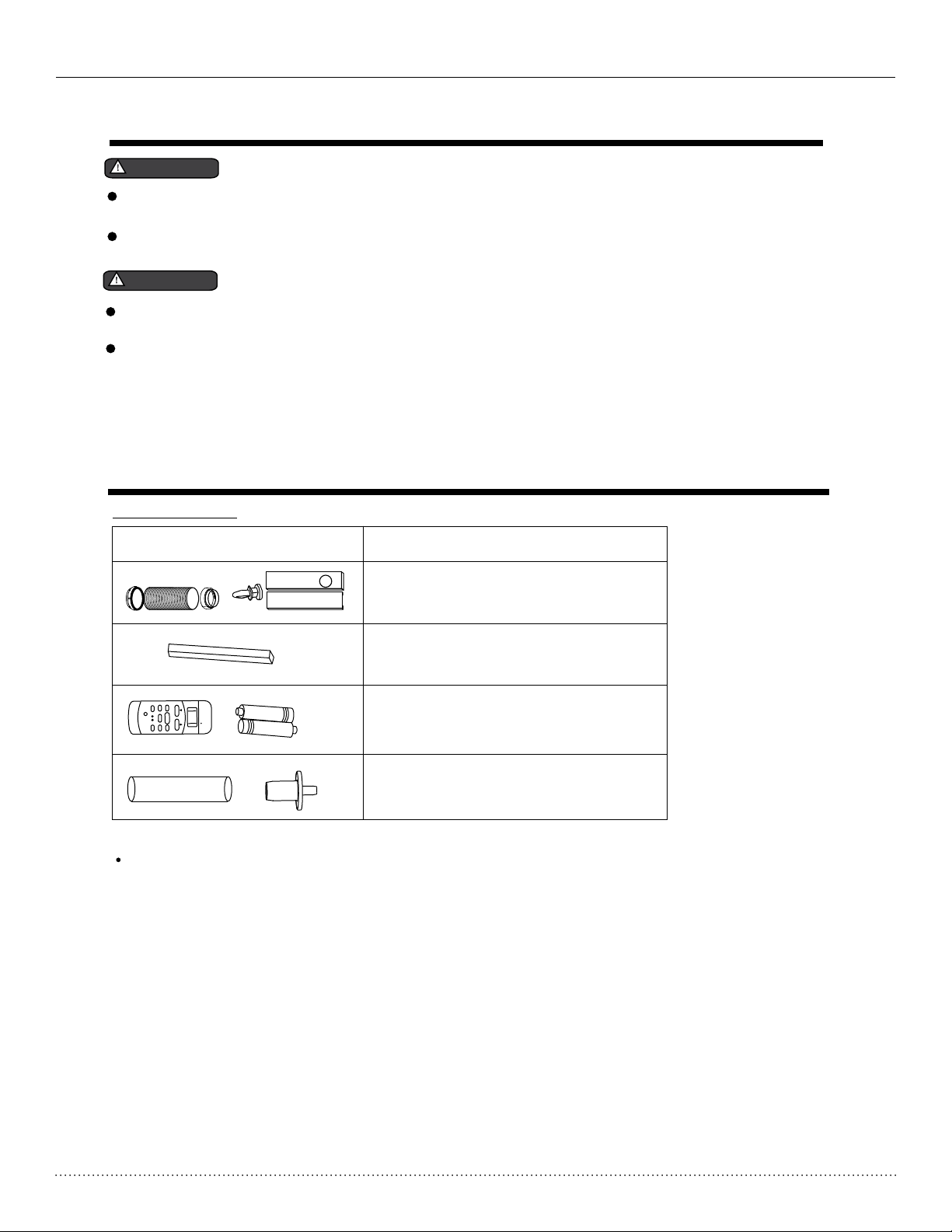
Accessories
PARTS :
PARTS NAME :
Exhaust hose and Apaptor
Window Slider Kit and bolt
Foam seal
AUTO
COOL
DRY
HEAT
SET TEMPERATURE( C)
MODE
SWING
ION
FOLLOW
ME
RESET LOCK
TEMP
ECONOMY
ON/OFF
LED
DISPLA
FAN SPEED
Y
TIMER OFF
TIMER ON
TURBO
FAN
HIGH
MED
LOW
Remote Controller and Batteries
Drain hose and drain hose adaptor
Check all the accessories are included in the package and please refer to the installation instructions for
their usage.
NOTE:
All the ill ustrations in this manual are for explana tion purposes only. Your air con ditioner
may be slig htly different. The actual sh ape of parts , accessories, unit, etc. sha ll prevail.
4
Page 5
Heat Controller, Inc. PSH-141A Installation, Operation & Maintenance
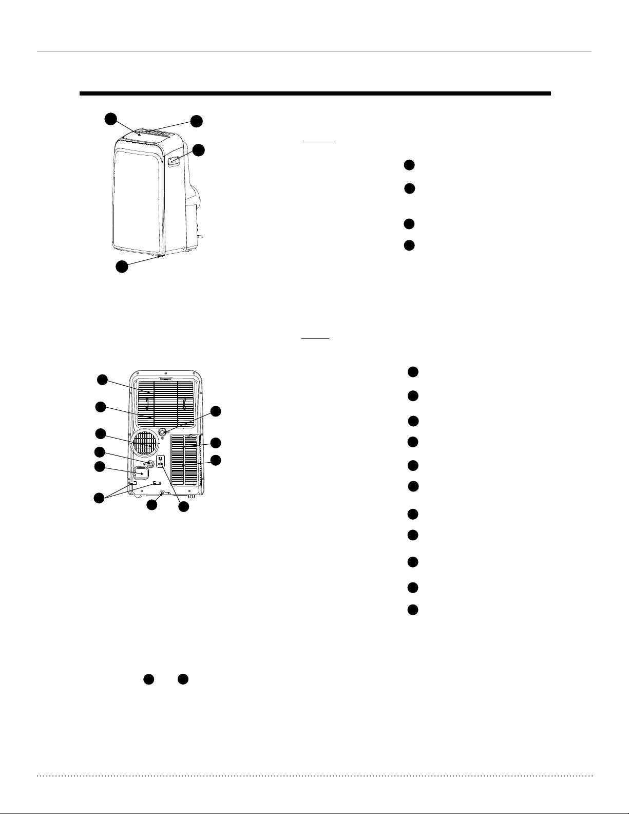
IDENTIFICATION OF PARTS
2
1
Front
4
Control panel
1
Horizontal louver blade
2
(swings automatically)
Casters
3
Carrying handles
4
(both sides)
3
Fig. 1
Rear
Upper air filter
5
6
7
8
9
15
14
13
5
(Behind the grille)
Upper air intake
6
7
Air outlet
8
9
Drai n outlet
Powe r cord outlet
10
Powe r cord buck le*
10
*Not es: Items and a re used to wr ap up and store t he power cord a nd plug whe n the unit is not i n use.
10
11
12
12
Fig.2
Bott om tray drain o utlet
11
Powe r plug sock et*
12
Lower air filter
13
(Behind the grille)
Lower air intake
14
15
Drai n outlet
5
Page 6

Installation, Operation & Maintenance PSH-141A Heat Controller, Inc.
AIR CONDITIONER FEATURES
ELECTRONIC CONT ROL OPERAT ING IN STRUCTI ONS
Before yo u begin, tho roughly familiarize yourself with the functions of the control panel a nd
remote co ntroller.
The unit can be controlled by the unit control panel alone or with the remote controller .
NOTE: Thi s manual does not inc lude Remote Contr oller Operation s, see the <<Remote
Control ler Instruction >> packed with the un it for details.
OPERATION PANEL OF THE AIR CONDITIONER
8
1
POWER button
Power switch on/off.
2
SLEEP button
Used to initiate the SLEEP operation.
FAN button
3
Controls the fan speed. Each time you press the
button, a different fan speed is selected in a
sequence as follows: LOW, MED, HI and AUTO.
The fan speed indicator light illuminates under
the selected fan settings except AUTO speed.
When Auto fan speed is selected, all of the fan
indicator lights turn off.
NOTE: On some models the fan speed may
not be adjustable when the unit is in Heat, Dry
or Auto modes, as the fan is automatically
controlled.
4
UP( ) and DOWN( ) buttons
Used to adjust (increase/decrease)
temperature settings(2 F/1 C increments)
in a range of 62 F(17 C) to 88 F(30 C) or
the TIMER setting in a range of 0~24hrs.
temperature in degrees Fahrenheit or degrees
Celsius. To convert from one to the other, press
and hold the Up and Down buttons at the same
time, for 3 seconds.
+
O O O O
NOTE: The control is capable of displaying
-
O O
2344567
MODE select button
5
Selects the appropriate operating mode.
Each time you press the button, a mode
is selected in a sequence that goes from
AUTO, COOL, DRY, FAN and HEAT. The
mode indicator light illuminates under the
selected mode setting.
6
TIMER button
Used to initiate the AUTO ON start time and
AUTO OFF stop time program, in conjuction
with the and buttons. The timer on/off
indicator light illuminates under the timer
on/off settings.
SWING button
7
Used to ini tiate the Auto swing feature.
When the sw ing mode is ON, press the
SWING but ton to stop the louve r at
the desir ed angle. Pr essing and holding
the swing b utton will restart the auto
swing fun ction.
LED Display
8
Shows th e set temperature in C
O
" F" and th e Auto-timer settings.
While in DRY or FAN mode, it displa ys
the room temperature.
NOTE: The control is capable of displaying
temperature in degrees Fahrenheit or degrees
Celsius. To convert from one to the other, press
+
-
1
O
" " or
Fig.3
6
Page 7

Heat Controller, Inc. PSH-141A Installation, Operation & Maintenance
OPERATING INSTRUCTIONS
Error cod es and protection c ode:
E1- Room te mperature sensor error-
Unplug th e unit and plug it back in.
If error re peats, call for ser vice.
E2- Evapo rator temperature sensor error Unplug th e unit and plug it back in.
If error re peats, call for ser vice.
E
3- Conens er tempera ture sensor error-
Unplug th e unit and plug it back in. If error
repeats , call for service.
E4- Displ ay panel com munication error-
Unplug th e unit and plug it back in.
If error re peats, call for ser vice.
P1- Botto m tray is full - Connect the
drain hos e and drain the collected
water awa y. If e rror repeats, call
for servi ce.
Operating Instructions
COOL operation
- Press the "MODE" button until the "COOL"
indicator light comes on.
- Press the ADJUST buttons "+" or " - " buttons to
select the desired room temperature.
- Press the "FAN SPEED" button to select the
desired fan speed.
HEAT operation
- Press the "MODE" button until the "HEAT"
indicator light comes on.
- Press the "+" or " - " buttons to select the desired
room temperature.
- Press the "FAN SPEED" button to select the
desired fan speed. For some models, the fan speed
can not be adjusted while the unit is in HEAT mode.
DRY operation
- Press the "MODE" button until the "DRY"
indicator light comes on.
- Under this mode, you cannot select a fan
speed or adjust the temperature. The fan
motor operates at LOW speed automatically.
- Keep windows and doors closed for the
best dehumidifying effect.
- Do not connect the duct to window.
(cooling only models without)
AUTO operation
- When you set the air conditioner in AUTO
mode, it will automatically select cooling,
heating or fan only operation depending
on what temperature you have selected
in relation to the actual room’s temperature.
- The air conditioner will cool / heat
automatically around the
temperature point set by you.
- Under AUTO mode, you can not
change the fan speed.
FAN operation
- Press the "MODE" button until the
"FAN " indicator light comes on.
- Press the "FAN SPEED" button to
choose the desired fan speed. The
temperature cannot be adjusted.
- Do not connect the duct to window.
TIMER operation
- When the un it is on, press the
Timer butt on to initiate the Auto-off
program , the TIMER OFF
indicat or light illuminates. Press the
(+) or (-) bu ttons to select the desired
time with in 5 seconds. Press the TIMER
button ag ain to initiate the Auto
on timer pr ogram, the TIM ER
ON indica tor light illuminates. Pres s
the (+) or (- ) buttons to select the
desired Au to-on star t time.
- When the un it is off, press the Timer
button to i nitiate the Auto-on start
program , press it again within five
seconds t o initiate the Auto-off stop
program .
- Press or ho l
change th e Auto time by 0.5 hour
increme nts, up to 10 hours, then
at 1 hour inc rements up to 24
hours. The control will c ount down
the time re maining until start.
- The system will automat ically revert
back to dis play the previous temper ature set ting if there is no operation
in a five sec ond period .
d the (+) or (- ) buttons to
7
Page 8
Installation, Operation & Maintenance PSH-141A Heat Controller, Inc.
OPERATING INSTRUCTIONS
- Turning th e unit ON or OFF at any
time or adj usting the timer setting
to 0.0 will c ancel the Auto On/Off timer
program .
- When an err or/malfunction (E1,E2,E 3
or E4) occu rs, the Auto On/Off
timed pro gram will al so be cancelled.
SLEEP operation
By pressing the sleep button, the set temperature will
increase(cooling) or decrease(heating) by 2 F/1 C
30 minutes. The temperature will then increase
(cooling) or decrease (heating) by another 2 F/1 C
O O
O O
after an additional 30 minutes. This new temperature will be maintained for 7 hours before it returns
to the originally selected temperature. This ends
the Sleep mode and the unit will continue to operate
as originally programmed.
NOTE: This feature is unavailable under FAN or
DRY mode.
Auto-Restart
If there is a l oss of power, once power is restor ed,
the unit wi ll automatically restart in t he last mode
it was oper ating in pri or to the power failure.
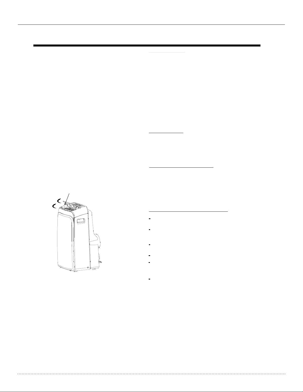
Swin g automatic ally
Fig. 4
Compressor Time Delay
After the u nit has stopped operating, it c an not
be restar ted for 3 minutes. This is to protect the
unit’s compressor. Ope ration wil l automatically
start aft er 3 minutes has passed.
Air flow direction adjustment
When the Po wer is ON, the louver opens fully
(Fig.4) .
Press the S WING button on the pa nel or
remote co ntroller to initiate the Auto swing
feature .
The louver will swing up an d down
automat ically.
Please do n ot adjust the louver manually.
To sto p the louver i n a desired angle, press
the swing b utton again while the louver is in
the locat ion you wish i t to st
ay in.
If the louv er is placed i n a position/angle
that affect s the coolin g or heating operation,
the unit wi ll automatically adjust the louver
angle.
8
Page 9

Heat Controller, Inc. PSH-141A Installation, Operation & Maintenance
INSTALLATION INSTRUCTIONS
INSTALLATION INSTRUCTIONS
Location
The air conditioner should be placed on a firm
foundation to minimize noise and virbration. For
safe and secure positioning, place the unit on a
smooth, level floor strong enough to support the unit.
B
A:1ft .- 3ft.( 30 cm-100c m)
A
Fig.5
B: 1ft. ( 30 cm)
The unit has casters to aid placement, but it should
only be rolled on smooth, flat surfaces. Use caution
when rolling on carpet surfaces. Do not attempt to
roll the unit over objects.
The unit must be placed within reach of a properly
rated grounded socket.
Horiz ont al
windo w
Never place any obstacles around the air inlet or
outlet of the unit.
Allow 1ft.-3ft.(30cm to 100cm) of space from the
wall with for efficient air-conditioning. (Fig.5)
Window slider kit Installation
Win dow Slide r Kit
Minim um: A
Maxim um: B
Fig.6
Your window slider kit has been designed to fit most
standard "Vertical" and "horizontal"window
applications. However, it may be necessary for you to
improvise/modify some aspects of the installation
procedures for certain types of windows. Please refer
to Fig. 6 & Fig.7 for minimum and maximum window
openings. Window slider kit can be fixed with a bolt
(see Fig.7a).
Horiz ont al
windo w
Win dow Slide r Kit
Minim um: A
Maxim um: B
bolt
Fig.7
Win dow slide r kit
Fig.7a
Note: If the window opening is less than the mentioned
minimum length of the window slider kit, cut the one
with a hole in it to fit the window opening.
Do never cut out the hole in window slider kit.
Minimum
in.
26-9/16
A
cm
67.5 48-1/2 123
B
Maximum
in.
cm
9
Page 10
Installation, Operation & Maintenance PSH-141A Heat Controller, Inc.
INSTALLATION INSTRUCTIONS
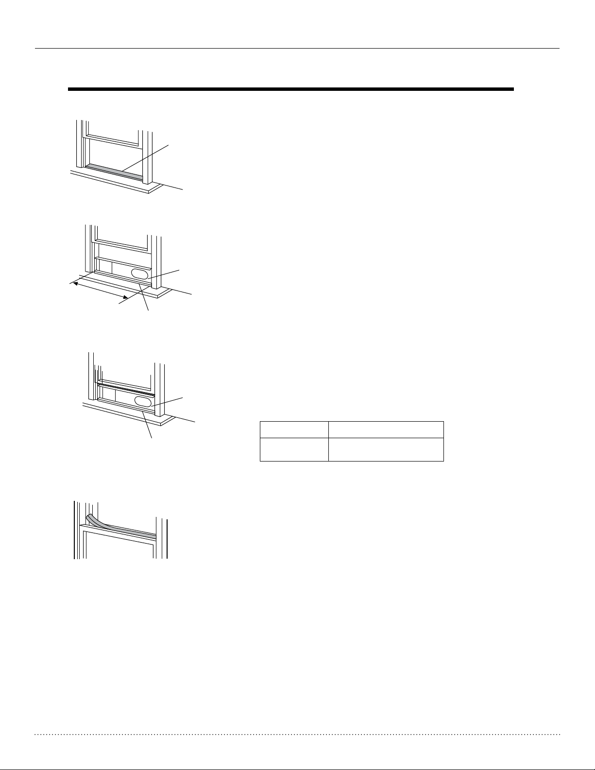
Installation in a double-hung sash
window
Foam seal A
(adhesive type)
1. Cut the foam seal (adhesive type) to the proper length and
attach it to the window stool. Fig.8
Fig. 8
2. Attach the window slider kit to the window stool. Adjust the
length of the window slider kit according to the width of
window, shorten the adjustable window kit if the width of
window is less than 26.5” (67.5 cm). Open the window sash
and place the window slider kit on the window stool. Fig.9
Window kit
3. Cut the foam seal (adhesive type) to the proper length
C
Window stool
Fig. 9
and attach it on the top of the window. Shown as in Fig.10
4. Close the window sash securely against the window.
5. Cut the foam seal to an appropriate length and seal the
open gap between the top window sash and outer window
sash. Shown as in Fig.11.
Window kit
C
Window stool
Min-max.
Fig. 10
26.5”~ 48.5” (67.5-123 cm)
Foam seal
Fig. 11
10
Page 11

Heat Controller, Inc. PSH-141A Installation, Operation & Maintenance
INSTALLATION INSTRUCTIONS
Installation in a sliding sash window
Window
panel
Foam seal A
(adhesive type)
Fig. 12
C
Fig. 13
1. Cut the foam seal (adhesive type) to the proper length and
attach it to the window frame. See Fig.12.
2. Attach the window slider kit to the window stool. Adjust the
length of the window slider kit according to the width of
window, shorten the adjustable window kit if the width of
window is less than 26.5” (67.5 cm). Open the window sash
and place the window slider kit on the window stool. See Fig.13.
3. Cut the foam seal (adhesive type) to the proper length
and attach it on the top of the window. Shown as in Fig.14.
4. Close the sliding sash securely against the window.
5. Cut the foam seal to an appropriate length and seal the
open gap between the top window sash and outer window
sash. Shown as in Fig.15.
C
Foam seal
Fig. 14
Fig. 15
Min-max.
26.5”~ 48.5” (67.5-123 cm)
11
Page 12
Installation, Operation & Maintenance PSH-141A Heat Controller, Inc.
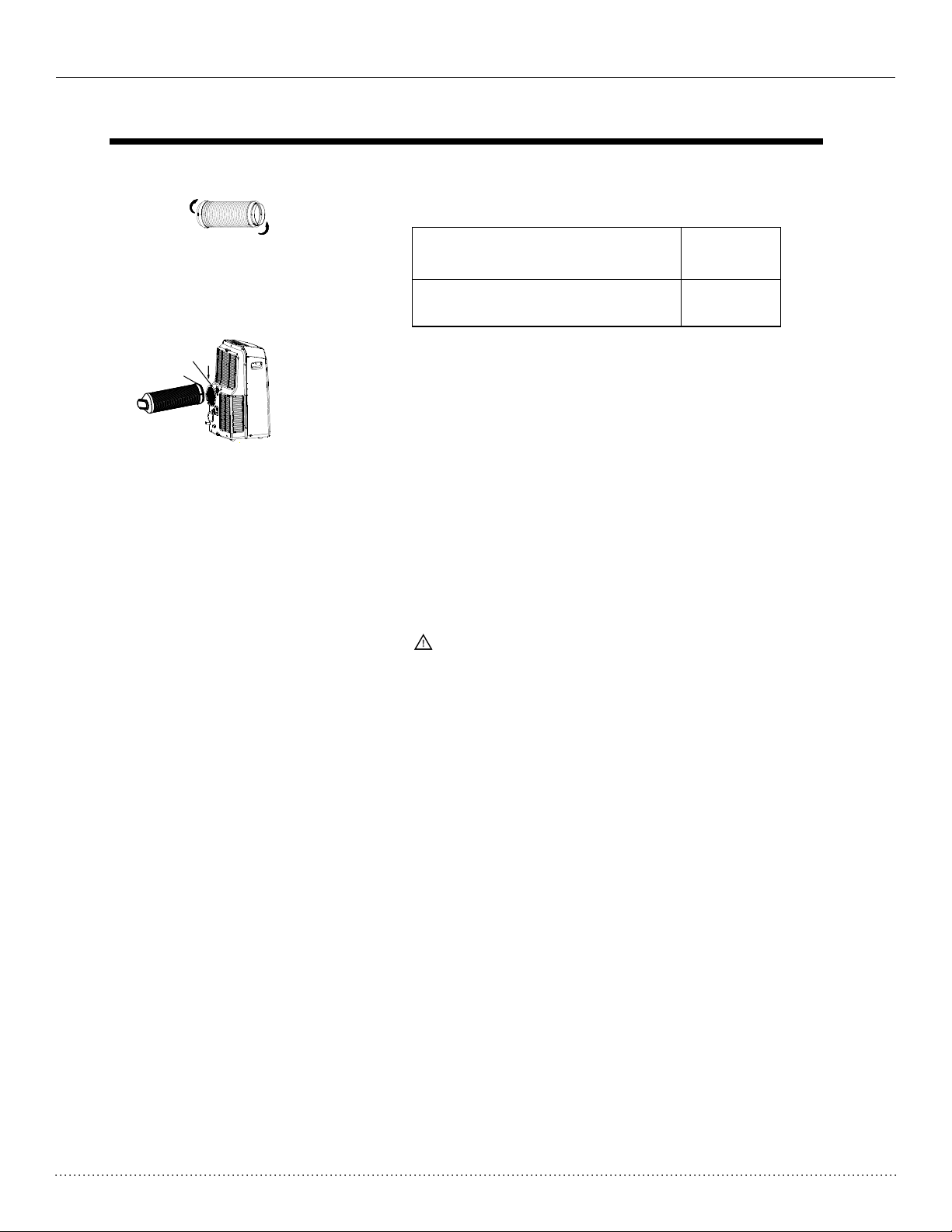
1. Install the adaptor onto the exhaust hose as shown in Fig.16.
INSTALLATION INSTRUCTIONS
Exhaust hose installation:
The exhaust hose and adaptor must be installed or removed
in accordance with the usage mode.
Hole seat
Hook
Fig. 16
COOL,HEAT or AUTO mode
FAN, OR DEHUMIDIIFY or mode
Install
Remove
Refer to the previous pages for window kit installation.
2. Insert the hook of the Exhaust hose into the hole seat of the
air outlet and slide down the Exhaust hose along the arrow
direction (See Fig.17) for installation.
Fig. 17
IMPORTANT:
DO NOT OVER EXTEND OR BEND THE EXHAUST HOSE
CAUTION:
Make sure that there are no obstacles around the air outlet of
the exhaust hose provide at least 1.5ft.(500mm) clearance
in order for the exhaust system to work properly.
12
Page 13

Heat Controller, Inc. PSH-141A Installation, Operation & Maintenance
INSTALLATION INSTRUCTIONS
Condensate drainage:
Cont inuous
drai n hose
¡
Remove the
upper drain plug
Remove th e
lower dra in plug
¡
drai n hose
adap tor
Fig. 18a
Cont inuous
drai n hose
drai n hose
adap tor
Fig. 18b
¡
Fig. 19a Fig. 19b
Fig. 20
- While operating in dry (dehumidify) mode, remove
the upper drain plug from the back of the unit, install
the drain connector (5/8 universal female mender) with
3 4 hose(locally purchased). For the models
without drain connector, just attach the drain
hose to the hole. Place the open end of the
hose adaptor directly over the drain area in your
basement floor. Please refer to Fig.18a.
- While operating in heating pump mode, remove the
lower drain plug from the back of the unit, install the
drain connector (5/8 universal female mender) with
3/4 hose(locally purchased). For the models
without drain connector, just attach the drain
hose to the hole. Place the open end of the
hose adaptor directly over the drain area in your
basement floor. Please refer to Fig.18b.
NOTE: Make sure the hose is secure so there are
no leaks. Direct the hose toward the drain, making
¡
sure that there are no kinks that will stop the water from
flowing. Place the end of the hose into the drain and
make sure the end of the hose is down to let the
water flow smoothly.(See Fig.18a,18b,19a). Do
not let it up.(See Fig.19b).
- When the water level of the bottom tray reaches
a predetermined level,
the digital display area shows "P1" . At this time
the air conditioning/dehumidification process will
immediately stop. However, the fan motor will
continue to operate(this is normal).
Carefully move the unit near a drain location,
remove the bottom drain plug and let the
water drain away (Fig.20). Reinstall the bottom
drain plug and restart the machine until the "P1"
symbol disappears. If the error repeats, call for
service.
NOTE: Be sure to reinstall the bottom drain plug
before using the unit.
the unit beeps 8 times,
13
Page 14

Installation, Operation & Maintenance PSH-141A Heat Controller, Inc.
CARE AND MAINTENANCE
Uppe r filter
(tak e out)
Remo ve the
scre w ,then
take t he lower
filt er out.
Uppe r filter
(ins tall)
Inst all the lower
filt er by using
the sc rew.
Fig.21
Fig. 22
CARE AND MAINTENANCE
IMPORTANT:
1) Be sure to unplug the unit before cleaning or servicing.
2) Do not use gasoline, paint thinner or other chemicals to clean
the unit.
3) Do not wash the unit directly under a tap or using a hose.
It may cause electrical danger.
4) If the power cord is damaged, it should be repaired by
an authorized servicer.
1. Air filter
- Clean the air filter at least once every two weeks.
- Removal
This unit has two filters. Take the upper filter out along the
the arrow direction (Fig.21),then take the filter down.
Remove the lower filter by loosening the screw, taking out
the filter as shown in Fig.21.
- Cleaning
Wash the air filter by immersing it gently in warm water
(about 104 F/40 C) with a neutral detergent. Rinse the filter
and dry it in a shady place.
- Installation
Insert the upper air filter after cleaning, and reinstall the lower
filter by using the screw (see Fig.22).
O O
Buckle
Power
cord
Power plug
Power plug
socket
Fig.23
Fig.24
2. Unit Cabinet
- Use a lint-free damp cloth with neutral detergent to clean
the cabinet. Finished by drying with a clean, dry cloth.
3. Unit storage when not in use
- Remove the rubber plug at the back of the unit and attach
a hose to the drain outlet
. Place the open end of the hose
directly over the drain area in your basement floor
(See Fig.18 & 19).
- Remove the plug from the bottom drain outlet, all the water
in the bottom tray will drain out (See Fig.21).
- Keep the appliance running in FAN mode for half a day in
a warm room to dry the appliance inside and prevent mold
from forming.
- Stop the appliance and unplug it, wrapped the cord and
bundle it with the buckle and plug the power plug into the
socket on the back of the unit. (Fig.23). Remove the batteries
from the remote controller.
- Clean the air filter and reinstall it.
- Unscrew the exhaust hose from the unit and pull out for
uninstallation (Fig.24).
14
Page 15

Heat Controller, Inc. PSH-141A Installation, Operation & Maintenance
TROUBLESHOOTING TIPS
TROUBLESHOOTING
PROBLEM
1. Unit does not
Start when
Pressing on/off
Button
2. Not cool enough
4. Noisy or vibration
5. Gurgling sound
POSSIBLE CAUSES
- P1 appears in the display window
- Room temperature is lower than
the set temperature.(Cooling mode)
- The windows or doors in the room
are not closed.
- There are heat sources inside the
room.
- Exhaust air duct is not connected or
blocked.
- Temperature setting is too high.
- Air filter is blocked by dust.
- The ground is not level or not flat
enough.
- The sound comes from the flowing
of the refrigerant inside the
air-conditioner.
SUGGESTED REMEDIES
Drain the water in the bottom tray.
Reset the temperature.
Make sure all the windows and
doors are closed.
Remove the heat sources if possible.
Connect the duct and make
sure it can function properly.
Decrease the set temperature.
Clean the air filter.
Place the unit on a flat, level
ground if possible.
It is normal.
6. Power shut off at
Heating mode
- The auto matic ov er heat
prot ection fun ction. Whe n the
temp erature at the air out let
exce ed 158 F/70 C, th e de vice
wi
ll s t op.
O
O
Switch on again after the unit
has cool down.
15
Page 16

3-2013
 Loading...