

Page 1
OWNER’S MANUAL
PORTABLE AIR CONDITIONER
Model: PE-91A
PE-121A
COOL - HEAT - DEHUMIDIFY
Page 2

INDEX
PLEASE READ CAREFULLY. KEEP THIS INSTRUCTION MANUAL FOR FUTURE
REFERENCE.
SECTION PAGE
1. BEFORE USE............................................................ 3
2. QUICK SET UP.......................................................... 4
3. INTRODUCTION........................................................ 5
4. SUGGESTIONS FOR USE ........................................ 5
5. SPECIFICATIONS...................................................... 6
6. PARTS & ACCESSORIES ......................................... 7
7. SAFETY ..................................................................... 8-9
8. INSTALLATION.......................................................... 10-11
9. OPERATION .............................................................. 12-17
10. DRAIN EXCESS CONDENSATE WATER ............................. 18
11. MAINTENANCE..................................................................... 19-20
12. TROUBLESHOOTING GUIDE............................................... 21
9.1 Control Panel................................................................
9.2 Remote Controller........................................................
9.3 Operation in Auto, Cool, Heat, Dry & Fan Mode........
9.4 Timer Setting Procedure..............................................
9.5 Air Flow Direction Control...........................................
12
13
14-15
16
17
13. WIRING DIAGRAM………………………………………………. 22
2
Heat Controller, Inc.
1900 Wellworth Avenue Jackson, MI 49203
Page 3
BEFORE USE
READ THIS ENTIRE INSTRUCTION MANUAL BEFORE USE
Keep your ORIGINAL purchase
receipt.
Your receipt is your proof of
purchase and may be necessary
for warranty service.
! A TTENTION !
This manual describes installation, operation, and maintenance of the
portable air conditioner product.
If you need assistance, please call:
CUSTOMER SERVICE
1-517-787-2100
FOR FUTURE REFERENCE, PLEASE RECORD THE FOLLOWING:
Model No.:
Serial No.:_________________
Date of Purchase: _______________________________
________________________________________________
Heat Controller, Inc.
3
1900 Wellworth Avenue Jackson, MI 49203
Page 4
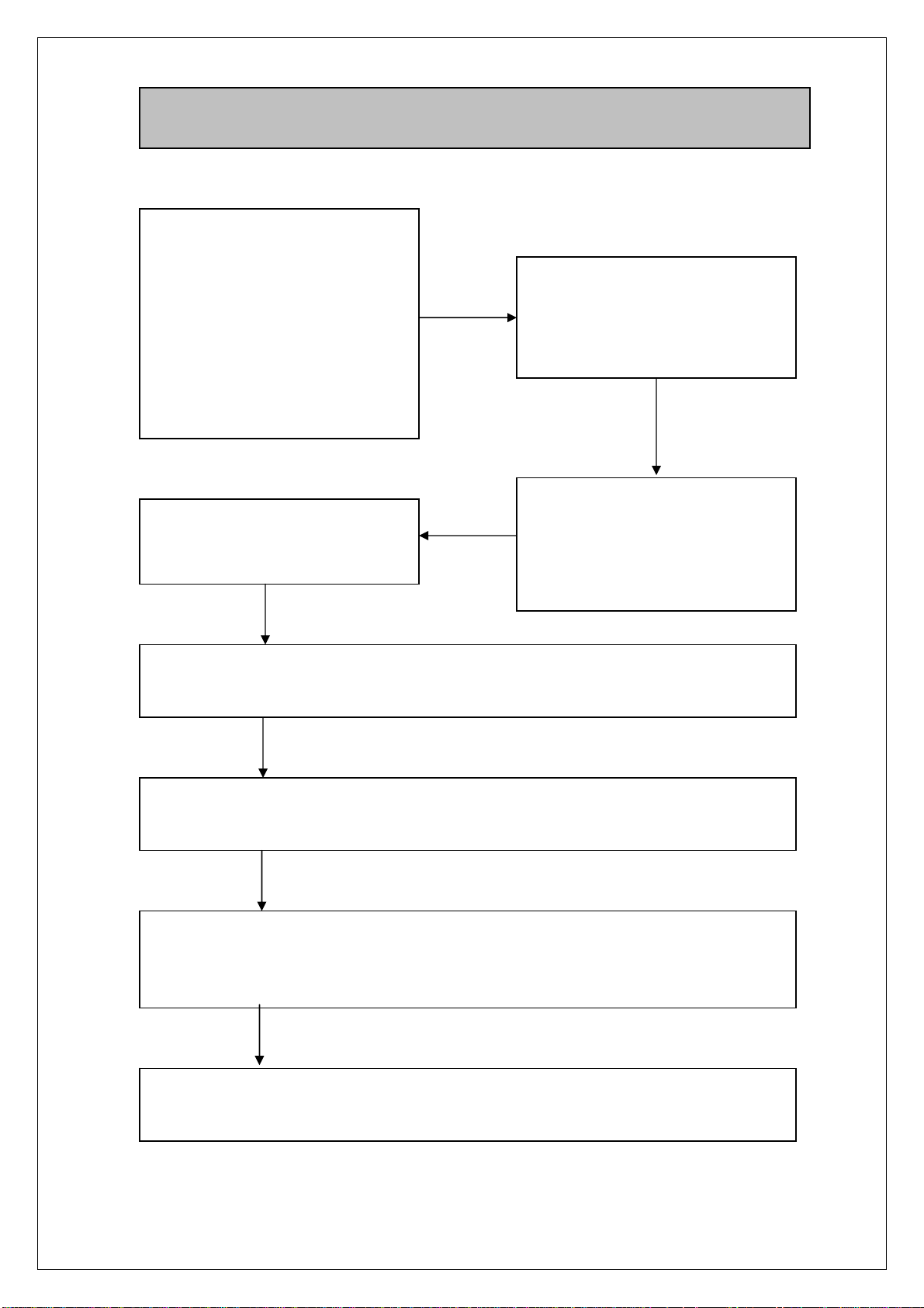
2.
QUICK SET UP
Unpack the unit:
• Remove the foam cap.
• With two people, lift and
remove the unit from the
foam packing base
without tilting the unit.
• Remove the plastic bag.
Test LCDI Plug. (Ref. Section
7, Safety Rules).
Check to see if unit is complete
including all parts and
accessories (Ref. Section 6,
Parts & Accessories).
Place the unit UPRIGHT to
allow the refrigerant and oil to
stabilize. Wait 3 hours before
using. (Ref. Section 7,
Safety).
Attach air inlet and air outlet hose. Follow instructions per Section 8,
Installation.
Plug the unit into a properly grounded 15 Amp, 115V AC, circuit. (Ref.
Section 7, Safety Rules).
Follow Section 9, Operation to set preferred function mode. When
Water-Full indicator illuminates, empty the residual condensate water. (Ref.
Section 10, Drain Excess Condensate Water).
Handle your unit with care. Move it gently. Always keep air filter clean.
Do not cover air inlet grid and air outlet grid.
Heat Controller, Inc.
4
1900 Wellworth Avenue Jackson, MI 49203
Page 5

3.
This Portable Air Conditioner is designed for improving living and working
comfort by adjusting the temperature and humidity in a room. Its mobility
makes it easy to use in various rooms.
This unit is provided with one outside air inlet hose and one hot-air outlet hose
to enhance cooling performance. This unit has an Auto Restart function. In
case of power failure, the unit will restart in the last setting selected when
power resumes.
To ensure the optimal efficiency of the air conditioner, keep doors and windows
closed. In order to optimize the functioning of your air conditioner, close
window coverings to minimize sun load in the room.
INTRODUCTION
This unit has a three-minute compressor delay protection circuit
4.
1. This unit is designed for use indoors only and is not intended for outdoor
use.
2. Do not locate the unit where furniture or other objects can obstruct the
cooling airflow on back or above unit.
3. Prevent any kink or sharp bend in the air inlet and hot-air outlet hoses.
4. Unit must always be used in an upright position.
5. After unpacking, place the unit upright to allow the refrigerant and oil to
stabilize. Wait 3 hours before using.
6. Place the unit on the floor not on a table or other elevated surface.
7. Keep the filter clean.
SUGGESTIONS FOR USE
Heat Controller, Inc.
5
1900 Wellworth Avenue Jackson, MI 49203
Page 6
5.
SPECIFICATIONS
PE-91A / PE-121A
Electrical Supply 115V / 60 Hz
Cooling Capacity (BTUH) 9000 / 12000
Heating Capacity (BTUH) 3412 / 4265
Cooling Amps 10.0 / 11.5
Heating Amps 8.7 / 10.9
Dehumidifying Capacity (Pts/Hr) 2.5 / 2.8
Refrigerant R22
Fan Speeds Low / Med / Hi
Airflow (CFM) 210
Noise Level dB(A) 51 / 52
Net Weight (lb) 85.5 / 87.5
Product Dimension (in) 19.1(W) x 19.4(D) x 31.9(H)
Max. Length of Air Inlet and Outlet Hose (in) 71
Programming Timer (hr) 1 - 24
Heat Controller, Inc.
6
1900 Wellworth Avenue Jackson, MI 49203
Page 7
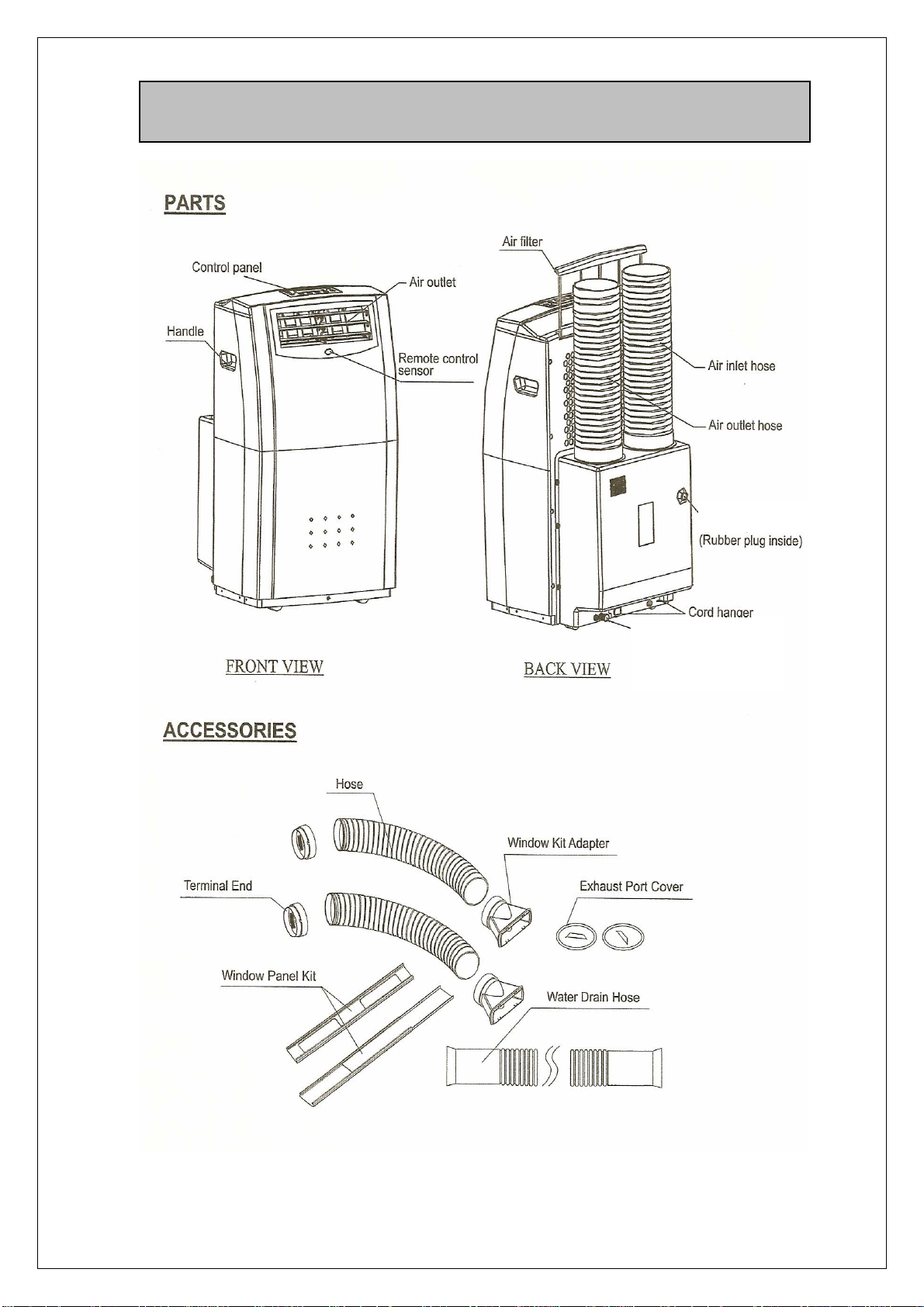
a.
6.
PARTS & ACCESSORIES
Upper drain port
Lower drain port
(Rubber plug inside)
Heat Controller, Inc.
7
1900 Wellworth Avenue Jackson, MI 49203
Page 8

7.
Connection to the main electrical supply must comply with local and national
electrical codes.
1. Do not damage the power cord.
2. Never lay this unit down. Operate in upright position only.
3. Be sure that air inlets and outlets are not blocked or covered up.
4. Never place anything on top of the unit.
5. Do not use this product outdoors.
6. Never connect the unit to a defective outlet.
7. Plug the unit into a properly grounded 15 Amp, 115V AC circuit. Check
your breaker box to determine which circuit the outlet is on. A dedicated
circuit is recommended.
8. Make sure that the unit is correctly connected before turning on the unit.
9. Do not use the plug as a disconnecting means.
10. DO NOT USE AN EXTENSION CORD for this unit.
11. Do not use an adapter plug to a two slot outlet unless proper grounding of
the outlet and/or ground wire is verified. Consult an Electrician.
12. Do not bend or crush the air inlet or air outlet hoses.
13. Do not allow children to play near the unit.
14. Do not place the power cord under a carpet.
15. Keep the area around the exhaust port/air inlet and air outlet hoses
sufficiently clean and make sure that it is not congested.
16. For any repairs, refer directly to our Customer Service Department.
Repairs carried out by unqualified people may cause damage or may
even be dangerous and may void the warranty.
DO NOT:
• Place objects inside the air outlet or air inlet grid.
• Use this unit inside closets or cabinets.
• Repair, disassemble and/or modify the unit by yourself.
• Use this unit in proximity to inflammable and/or explosive substances.
• Operate this unit without filter.
Before cleaning this unit, make sure that it is unplugged. Do not wash the unit
with water, gasoline or solvents of any kind. (See Section 11).
To avoid the risk of shock, the product should never be used in bathrooms,
shower rooms, or in any other steamy or wet areas.
Do not use the unit on a table as the unit is supported by wheels. Place unit on
level floor.
SAFETY
Heat Controller, Inc.
8
1900 Wellworth Avenue Jackson, MI 49203
Page 9
7.
SAFETY (continued)
This unit is provided with Leakage Current Detection and Interruption circuit
(LCDI) built into the plug of the power supply cord. This device provides
protection to reduce the risk of fire due to arcing faults in the power supply
cord. Before use, follow the “Plug Testing Instructions” to ensure that the
LCDI circuit functions properly.
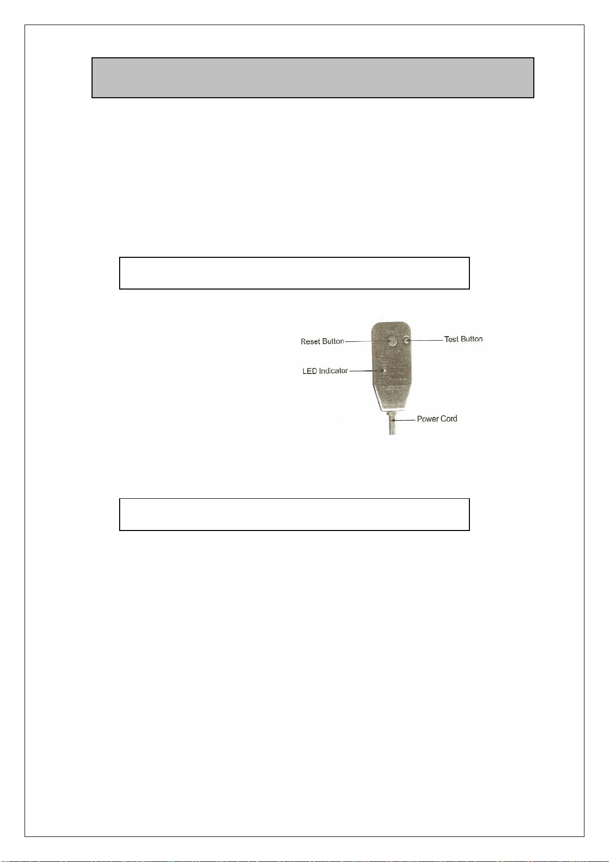
PLUG TESTING INSTRUCTIONS:
1. Press Test Button.
It should trip.
2. Press Reset Button
firmly for use. Reset
Button may require
pressure to engage.
(Plug on unit may vary from picture.)
DO NOT USE IF ABOVE TEST FAILS
Do not use the TEST and RESET buttons as an on/off switch. They are
only meant to be used for periodically checking the LCDI plug.
CALL CUSTOMER SERVICE IF TEST FAILS.
Replace defective cords only with genuine replacement parts from
Heat Controller.
Heat Controller, Inc.
9
1900 Wellworth Avenue Jackson, MI 49203
Page 10

8.
INSTALLATION
When this portable air conditioner operates in the cool mode, fresh outdoor air
must be directed into the unit and hot air must be exhausted out of the room to
complete heat exchange of the condenser. When the unit operates in FAN or
HEAT mode, no outdoor air is used hence it is not necessary to complete
window kit installation.
Installation Kit:
Air Inlet & Air Outlet Hose (2 sets)
Unit with Hoses Attached Cover the Exhaust Port When Unit Not in Use
Telescoping Window Panel Kit
There are two exhaust ports at the back of the unit. Cover the exhaust ports
when unit is not in use. To ready unit for installation, remove the exhaust port
cover by turning in a counter-clockwise direction.
10
Heat Controller, Inc.
1900 Wellworth Avenue Jackson, MI 49203
Page 11
8.
INSTALLATION
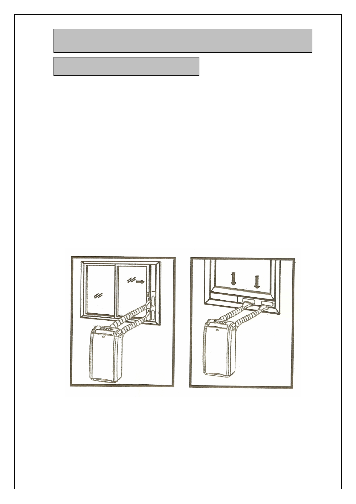
8.1 Installation Procedures
1. Measure the window the unit will be installed into and adjust the telescoping
Window Panels to fit into the window. If window is either too wide or too
tall, fill the remaining space with foam or other appropriate material. Make
sure that the holes on the Window Panel are exposed for connection of
Window Kit Adaptor.
2. Screw the hose clockwise into the Terminal End, and the other end of the
hose to the Window Kit Adaptor. Apply same procedures to both air inlet
hose and air outlet hose.
3. Secure the Terminal End to the Exhaust Port. Apply same procedures to
both air inlet hose and air outlet hose.
4. Connect the Window Kit Adaptor to each of the holes on the Window Panel.
VERTICAL HORIZONTAL
Heat Controller, Inc.
11
1900 Wellworth Avenue Jackson, MI 49203
Page 12

9.
y
9.1 Control Panel and Displa
Dry Mode
OPERATION
NOTE: To toggle the displayed temperature between °C and °F, press the
ON/OFF button for approximately 20 seconds and then release. (The °F printed
on the Control Panel will remain unchanged.)
.
Heat Controller, Inc.
12
1900 Wellworth Avenue Jackson, MI 49203
Page 13

9.
9.2 Remote Controller
OPERATION
ON/ OFF
ON OFF
TI M ER
TIMER
TEMP/ TI M E
TEMP/TIME
FAN SPEED
FAN SPEED
MODE
MODE
Fig. Remote Controller
The buttons on the Remote Controller perform the same functions as the
equivalent button on the Control Panel.
The Remote Controller uses lithium battery Model CR2025. Install battery
before using the Remote Controller.
13
Heat Controller, Inc.
1900 Wellworth Avenue Jackson, MI 49203
Page 14

9.
OPERATION
9.3 Auto, Cool, Heat, Dry, Fan Mode
You can operate the unit using the Control Panel on the unit, or with the
Remote Controller.
Auto Mode:
1. Plug the Power Cord into the power outlet.
2. Turn on the unit by pressing the ON/OFF Button on the Control Panel.
3. Press the Mode Button until the signal “ “ appears on the display.
4. Select the fan speed by using the FAN button.
During the AUTO mode, the unit will operate in HEAT mode when the room
temperature is below 70°F.
The unit will operate in FAN only mode when the room temperature is between
70°F and 80°F.
The unit will operate in COOL mode when the room temperature is above 80°F.
Cool Mode:
1. Plug the Power Cord into the power outlet.
2. Turn on the unit by pressing the ON/OFF Button on the Control Panel.
3. Press the Mode Button until the signal appears on the display.
4. Set the room temperature to your desired room temperature with
Temperature Changing Button.
5. Set temperature range from 64°F to 90°F.
6. Recommended temperature for your comfort: is 82°F to 86°F.
7. Select fan speed by pressing the FAN Button.
Heat Controller, Inc.
14
1900 Wellworth Avenue Jackson, MI 49203
Page 15

9.
OPERATION
9.3 Auto, Cool, Heat, Dry, Fan Mode
Heat Mode:
1. Plug the Power Cord into the power outlet.
2. Turn on the unit by pressing the ON/OFF Button on the Control Panel.
3. Press the Mode Button until signal “ “ appears on the display.
4. Set the room temperature to your desired room temperature with
Temperature Changing Button.
Then set temperature range from 60°F to 82°F.
We recommend temperature for your comfort between 69°F to 75°F.
5. Select the fan speed by pressing the Fan Speed Button. It is
recommended to use a low fan setting.
The Heating Function is provided by an electric heat element. The
compressor will not operate in HEA T Mode. It is not necessary to connect any
of the exhaust hoses to the unit.
Dry Mode:
1. Plug the Power Cord into the power outlet.
2. Turn on the unit by pressing the ON/OFF Button on the Control Panel.
3. Press the Mode Button until the signal “ “ appears on the display.
4. Set the room temperature to your desired room temperature with
temperature change button.
5. Keep the windows and the doors closed to aid the effectiveness.
6. The unit will only operate at low fan speed in Dry Mode. It is
recommended not to install the exhaust hose for the best dehumidifying
effect; however, the room may become too warm for comfort. In this case,
the exhaust hose should be used.
NOTE: The unit will not perform dehumidifying when the room temperature
is lower than 64°F.
Fan Only Mode:
1. Plug the Power Cord into the power outlet.
2. Turn on the unit by pressing the ON/OFF Button on the Control Panel.
3. Press the Mode Button until signal appears on the display.
4. Select the fan speed by pressing the Fan Speed Button.
Heat Controller, Inc.
15
1900 Wellworth Avenue Jackson, MI 49203
Page 16

9.
OPERATION
9.4 Timer Setting Procedure
ON-TIMER Program Setting:
When the unit is OFF, you can program the ON TIMER to start the unit after desired
number of hours. Procedure:
Preset
desired
operation
mode.
Press TIMER
button. Digit
“3” will flash
on LED
display.
TIMER LED
indicator will
illuminate.
Press
or
button to
desired
hours.
Number
of hours
will
appear
on LED
HOW TO CANCEL ON-TIMER Program Setting:
Press TIMER button.
Number of hours will
flash on LED display
Press TIMER button again.
Number of hours will disappear on
LED display. TIMER LED
indicator light will turn off.
10-second
pause after
pressing
or
button
signals
completion of
timer
programming.
Number of hours on LED
display will count down as
time lapses. When the
display shows “0” , meaning
programmed hour expires, the
product will start operation in
the preset
mode. If you do
not preset mode before
setting ON TIMER, the unit
will start in the mode of last
operation.
ON-TIMER program
cancelled.
OFF-TIMER Program Setting:
Press TIMER
button. Digit
“3” will flash on
LED display.
TIMER LED
indicator will
illuminate.
Press or
button to
your desired
hours.
Number of
hours will
appear on LED
display.
10-second pause after
pressing
button signals
completion of timer
programming. Indicator
will illuminate.
HOW TO CANCEL OFF-TIMER Program Setting:
Press TIMER button.
Number of hours will
flash on LED display
Press TIMER button again.
TIMER LED indicator will turn off.
Set temperature will appear on
LED display.
16
Heat Controller, Inc.
1900 Wellworth Avenue Jackson, MI 49203
or
When the
programmed hour
expires, the product
will stop.
OFF-TIMER program
cancelled.
Page 17

9.
OPERATION
9.5 Air Flow Direction Control
Horizontal Swing Strip
Press button. The horizontal swing strip controls the up-down
H-SWING
air direction and will move up and down automatically. Release
H-SWING button when the horizontal strip comes to your desired direction.
Vertical Swing Strip
Press button once. The vertical strip controls left/right air
V-SWING
direction and will swing left and right automatically. Press the V-SWING
button again when the vertical strip comes to your desired direction, the
vertical strip will stop.
Heat Controller, Inc.
17
1900 Wellworth Avenue Jackson, MI 49203
Page 18

10.
DRAIN EXCESS CONDENSATE WATER
Condensate Disposal:
Under normal operating conditions, this unit is designed to dispose of
condensate collected via an internal system that pumps water onto the hot
condenser coil for re-evaporation. It is then expelled to the outdoors via the
air outlet hose. If the unit is operated for prolonged periods during very high
humidity conditions, this system may become overwhelmed and the unit will
shut off. Excess water must be drained from the unit before it will restart.
Lower Drain Port
Upper Drain Port
Drain Water from Upper Drain Port:
Procedures: Connect the Water Drain House to the Upper Drain Port
allowing water to flow to a water bucket. (See above illustration).
Remember to reinstall the cap on Upper Drain Port after draining water . The
Upper Drain Port can be used if a floor drain or some other means of
disposing of condensate is not available.
Drain Water from Lower Drain Port: (Before Long Term Storage Only)
Procedures: Remove the Rubber Drain Plug on Lower Drain Port.
Connect the Water Drain Hose to allow water to drain to a floor drain or other
water outlet. Remember to reinstall the Rubber Drain Plug after draining
water.
Heat Controller, Inc.
18
1900 Wellworth Avenue Jackson, MI 49203
Page 19

11.
A
MAINTENANCE
MAKE SURE POWER SUPPLY IS SWITCHED OFF AND THE PLUG IS
PULLED OUT OF THE POWER OUTLET BEFORE ANY MAINTENANCE IS
PERFORMED.
• Do not immerse the unit in water or other liquids.
• Do not pour liquids onto the unit.
Clean the Filter
If the filter is blocked with dust, the airflow volume will reduce and the cooling
effect will be reduced.
• It is recommended to clean the filter once every two weeks or as
needed.
• Remove the filter from the back of the unit by pulling straight up. Wash
the filter gently with warm water (about 104°F.)
• Dry it thoroughly and then place it back into the product.
• Do not bend the filter.
Clean Exterior Surface of the Unit
• Clean with a damp sponge.
• Dry it with a clean, soft cloth.
• Never use alcohol or any product containing solvents.
Long-Term Storage
t the end of the season, or when you do not plan to use the unit for an
extended period of time, we recommend that you take the following steps:
1. Drain water from the lower drain port.
2. Clean the filter.
3. Store the power cord
Heat Controller, Inc.
Upper Drain Port
Lower Drain Port
19
1900 Wellworth Avenue Jackson, MI 49203
Page 20

11.
MAINTENANCE
11.1 Storing the Power Cord
To avoid damage to the power cord when the unit is not in use, always store the
power cord at the back of the unit in its original location (as shown in the figure
below).
Heat Controller, Inc.
20
1900 Wellworth Avenue Jackson, MI 49203
Page 21

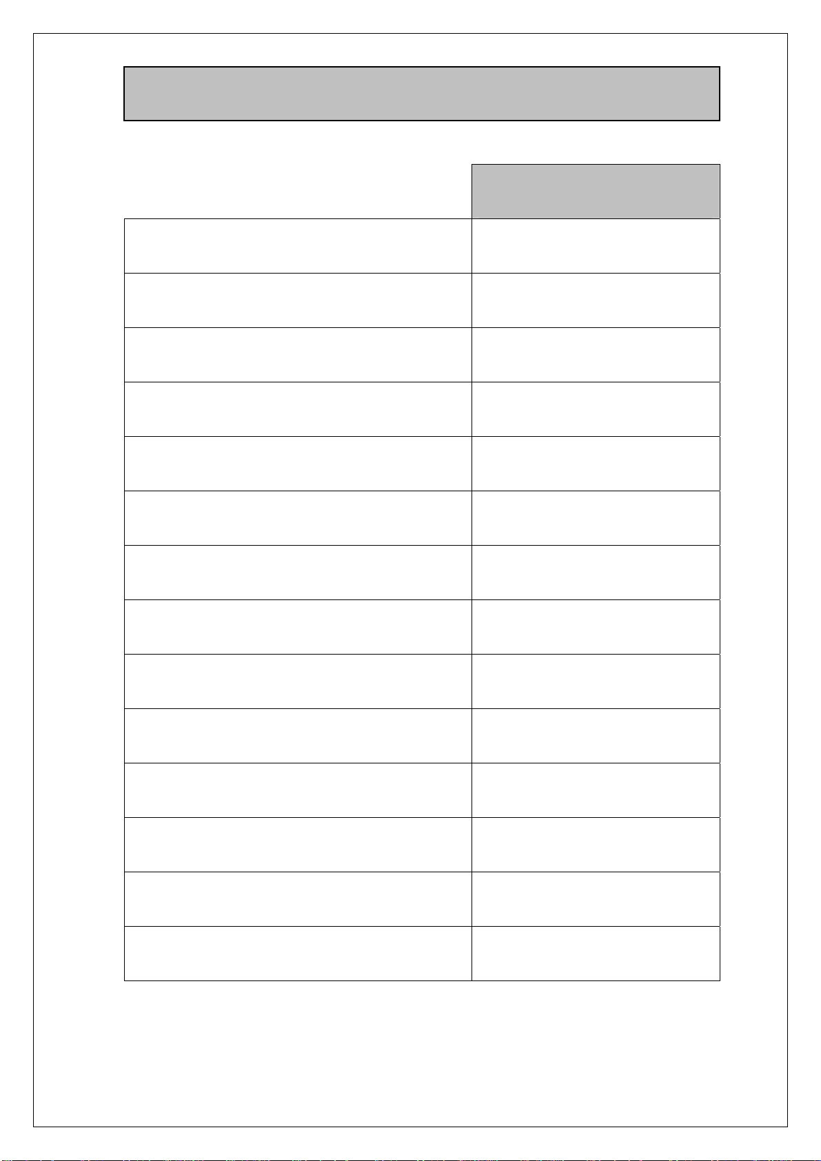
12.
TROUBLE SHOOTING
Problem Cause Solution
The unit doesn’t run
no cooling even
though it is in the
cooling mode
The unit seems to do
little cooling or does
not cool quickly
Power failure or plug is not
correctly inserted in the socket
Circuit breaker or line fuse has
been tripped
Power supply voltage is too low Call your Electrician
The room temperature is not at
working range
The set temperature is too high Re-set the temperature to a lower
The filter is dirty and obstructed Clean the filer
Evaporator air is blocked Remove the blockage
The air intake and outlet ducts of
the condenser side are obstructed
There is direct sunshine into room Close the curtains or blinds
The unit is set on dehumidifying
mode
Set at low fan speed Re-set the fan speed at high
Restore the power supply or
reset LCDI
Call your Electrician
Check your room temperature The unit has only fan,
temperature
Check both of the ducts
Set at cooling mode
speed
The unit has worked
for a long time, but the
room is not cold
enough
Too noisy
The unit stops cooling
suddenly, only the fan
works and the
Water-Full indicator
display on the
control pane is on
Heat Controller, Inc.
Windows or doors are open. Close all of the windows and
doors when the unit is working
Too many people in the room Turn on other cooling unit
Something else in the room
produces heat
The room is not well insulated,
such as sunrooms, garages,
attics, etc.
The unit is not sitting evenly Place the unit on an even surface
The floor underneath the unit is
uneven
The environment is too wet and
the condensate water in the unit is
full
21
1900 Wellworth Avenue Jackson, MI 49203
Turn off these products
Change the position
Empty the water inside the unit.
Connect a pipe to the upper drain
port (refer to drawing in PARTS
Of Unit) at the back of the unit
then restart the unit. Wait for
approximately 1 hour to let
condensor side fan blow out the
water
Page 22

13. WIRING DIAGRAM
Fan Mot or For
C1: Runni ng Capac i t or
For Fan Mot or of
Condens or Si de
C2: Runni ng Capac i t or
For Compr essor
C3: Runni ng Capac i t or
For Fan Mot or of
Evapor at or Si de
POWER
SUPPLY
N
L
G
C1
Condensor Si de
Cut - o f f
Tem perat ur e
Li mit
El ect r i cal
Heat er
Tem perat ur e
Li mit
ELECTRI CAL DI AGRAM FOR
Mobi l e Ai r Condi t i oner
Compressor
S
H
L
NO
WATER
PUM P
Swi n g Mot or
For Hori zont al
Swi n g St r i p
Microchip
Pr oc es s or
Prot ect or
C
R
C2
AC- N
NO
COM
Fuse
COM
3. 15A
Mot or For
Evapor at or Si de
C3
Cut - o f f
LI
MI
HI
WAT ER
Mai n
SM
5C
Swi n g Mot or
For Ver t i c al
Swi n g St r i p
SM
UP/ DOWN
LEFT/ RI GHT
5C
Cont r ol l er PCB
3C
Room
Tem perat ur e
Sensor
Wat er Level
Det ect or
Hr
Cont r ol Panel
PCB
Transf orm er
4C
7C
Si gnal Rec ei ver PCB
Heat Controller, Inc.
22
1900 Wellworth Avenue Jackson, MI 49203
Page 23

01/07
Design, material, performance data and components
subject to change without notice.
1900 Wellworth Ave., Jackson, Michigan 49203 • Ph. 517-787-2100 • Fax 517-787-9341
THE QUALITY LEADER IN CONDITIONING AIR
www.heatcontroller.com
 Loading...