

Page 1
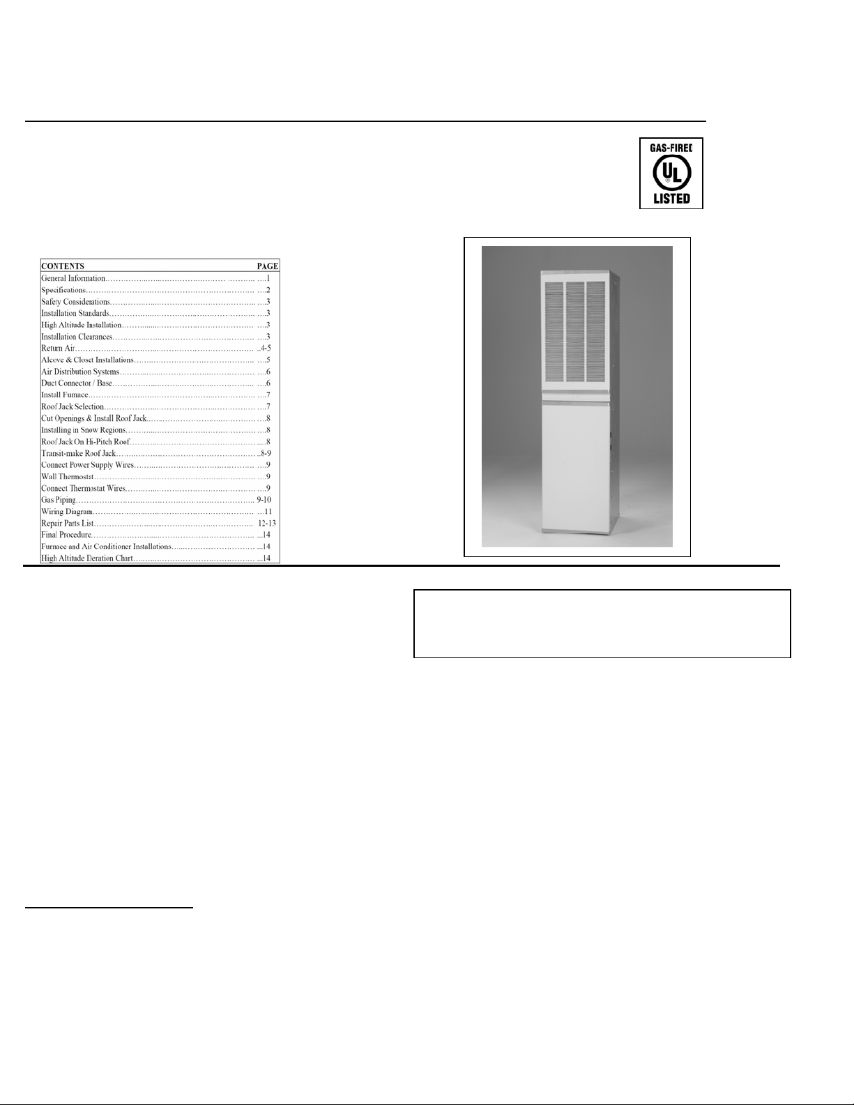
MGD Series Gas Furnace Installation Instructions
INSTALLATION INSTRUCTIONS
SEALED COMBUSTION
DOWNFLOW MGD SERIES
GAS FURNACE SIZES 60, 75, 90
FOR INSTALLATION IN: MANUFACTURED (MOBILE) CAUTION: READ ALL SAFETY GUIDES
HOMES, RECREATIONAL VEHICLES, PARK MODELS, BEFORE INSTALLING THIS FURNACE
MODULAR HOMES AND BUILDINGS
GENERAL INFORMATION
These down flow sealed combustion furnaces install in
Manufactured Homes, Recreational Vehicles or Modular
Construction. The furnaces conform to Part 3280 (a) (2) of
HUD Manufactured Homes Construction and Safety
Standards. They must be installed only with listed RJ-Roof
Jack, Sealed Combustion venting system.
NOTE: These instructions are intended to assist qualified
individuals experienced in the installation of heating
equipment.
Some state and local codes require installation personnel to be
licensed. Read all instructions before starting the installation.
SAVE THIS MANUAL
WARNING-RISK OF FIRE OR ELECTRICAL SHOCK
Only qualified service personnel shall be used to install
and provide maintenance of this furnace.
NOTICE – Furnace set-up and any adjustment needed is
responsibility of the installer/ retailer/ contractor and is not
covered by the furnace manufacturers warranty.
CHECKLIST: FURNACE START-UP
1. Has furnace roof jack crown been correctly installed?
2. Has the furnace gas valve and burner orifice been
cleaned?
3. Is the gas line outlet pressure set for the fuel used?
4. If the home uses a crossover air connector duct, is it
installed per homebuilders installation instructions?
5. Has furnace been operated through complete heating
cycle?
Heat Controller, Inc. Jackson, MI 49203 MGD Installation Instructions 1
Page 2
MGD Series Gas Furnace Installation Instructions
SPECIFICATIONS
80 AFUE- AUTOMATIC HOT SURFACE
IGNITION
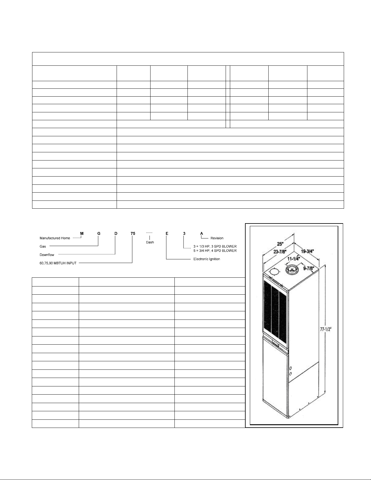
Model No. MGD60-E3A MGD75-E3A MGD90-E3A MGD60-E5A MGD75-E5A MGD90-E5A
Input, BTUH 60,000 75,000 90,000 60,000 75,000 90,000
Output, BTUH 48,000 60,000 72,000 48,000 60,000 72,000
AFUE, % 80.0 81.0 80.0 80.0 81.0 80.0
With A-Coil Cabinet YES YES YES YES YES YES
Ignition Type Auto-Elect Auto-Elect Auto-Elect Auto-Elect Auto-Elect Auto-Elect
Air Temperature Rise, Range-F 40-70 45-75 50-80 40-70 45-75 50-80
Blower 10 X 8, 1/3 HP, 3 SPD 10 X 8, 3/4 HP, 4 SPD
Designed Max Outlet Air Temp-F
Max. External SP (Duct),In. W.C. .30 Heating
Factory Equipped Fuel Natural Gas (Factory Equipped) - LP Orfice Furnished
High Altitude For elevations above 2,000 feet, reduce input 4% for each 1,000 ft. elevation above sea level
Furnace Flue Pipe Must Use RJS Roof Jack for Sloped Roof or RJF Roof Jack for Flat Roof
Gas Connection 1/2" FPT
Electric Service 115 VAC, 60 HZ, 1 PH
Fuse or Circuit Breaker 15 Amp
Thermostat Circuit 24VAC, 60Hz, 40VA
Filters 1-16"x40"x1" Washable
PRODUCT CODE
165 °
PART NO. DESCRIPTION NOTES
90-RJF1729-AL Body, Roof Jack, Gas-FLAT Height 94 1/2 X 106 1/2
90-RJF2551-AL Body, Roof Jack, Gas-FLAT Height 102 1/2 X 128 1/2
90-RJS1729-AL Body, Roof Jack, Gas-SLOPE 3/12 Height 94 1/2 X 106 1/2
90-RJS2551-AL Body, Roof Jack, Gas-SLOPE 3/12 Height 102 1/2 X 128 1/2
90-RJS3868-AL Body, Roof Jack, Gas-SLOPE 3/12 Height 115 1/2 X 145 1/2
90-RJS6399-AL Body, Roof Jack, Gas-SLOPE 3/12 Height 140 1/2 X 176 1/2
90-RJCRWN-AL Crown, Roof Jack, Gas Use w/ Gas Roof Jack Body
90-TRN-RNG Ceiling Trim Ring, Roof Jack Trim out to inside RJ - Pipe
90-OUTXT16-AL Roof Jack Outdoor Extension - Gas 16" Extend pipes / crown - 16 in.
90-INXST10-AL Roof Jack Indoor Extension - Gas 10" Extend pipes / crown - 10 in.
90-RJS56 5-6/ 12 Slope, Roof Saddle Adapter Add to RJS 3/12 Roof Jack
90-DCU0-01 86AA0013 Duct Conn + 87FB0005 Flr Base Floor to Duck 1 in. - 4 in.
90-DCU0-02 86AA0014 Duct Conn + 87FB0005 Flr Base Floor to Duck 6 in. - 8 in. STD
90-DCU0-03 86AA0015 Duct Conn + 87FB0005 Flr Base Floor to Duck 8 in. - 12 in.
90-CABEXT4 White, Top, Cabinet Extender Plate Fill alcove 76" top opening
87-1008-3/12A1 A/C Blower, 3 Speed - 1/3 HP 2 - 4 Ton A/C
87-1008-4/16A1 A/C Blower, 3 Speed - 3/4 HP 2 - 5 Ton A/C
Heat Controller, Inc. Jackson, MI 49203 MGD Installation Instructions 2
Page 3
MGD Series Gas Furnace Installation Instructions
SAFETY CONSIDERATIONS INSTALLATION STANDARDS
• ELECTRIC POWER - turn off all electrical
power to furnace before performing any
maintenance or service on unit. Failure to take
this precaution may result in personal injury due
to electrical shock.
• SERVICE - a qualified service technician
should service this unit. Fuel burning appliances
can generate toxic flue products. Modification of
the appliance can cause carbon monoxide in
deadly amounts. To prevent a safety hazard,
maintain this
appliance in a safe operating manner and do not
modify.
• DO NOT modify vent or operate the unit with a
blocked vent or inlet air pipe.
• DO NOT re-drill a burner orifice. If the orifice
size must be changed, use only a new orifice.
• DO NOT use matches, lighters, candles, or
other sources of open flame to check for gas
leaks.
• PROPER maintenance for this unit requires
certain mechanical skills and tools. If you are at
all uncertain, contact your Heating Service Co.
for maintenance and service.
• CONSULT with a service technician for any
problems or questions you may have pertaining
to this appliance.
• ALWAYS inspect the appliance before starting
a new heating season, paying special attention to
vent pipes and fuel lines.
NOTE: The words “Shall” or “Must” indicate a
requirement, which is essential to satisfactory and safe
furnace performance.
The words “Should” or “May” indicate a recommendation
which may be helpful or enhance performance.
CODE COMPLIANCE
The installer shall become familiar with and follow all local
codes and regulations which govern the installation of this
furnace. Where applicable, local codes may take precedence.
• Federal Manufactured Home Construction and Safety
Standards – HUD Title 24, Part 3280.
• National Fuel Gas Code – ANSI-Z223.1/NFPA-54
• Unit electrical wiring and grounding shall comply with
National Electrical Code – ANSI/NFPA-70
• “M anufactured Housing” – NFPA-501 and Fi re Safety Crit eria
for Mobile Home Installations – NFPA 501A
• “Recreational Vehicles” – ANSI – 119/NFPA – 501C
HIGH ALTITUDE INSTALLATION
For elevations above 2,000 feet derate furnace input 4% for each
1,000 feet of elevation above sea level. Furnace deration is
accomplished by reducing the burner orifice size. See
DERATING CHART for orifice size and CONVERSION
INSTRUCTIONS, Page 16.
INSTALLATION CLEARANCES
These furnaces are design certified for the following minimum
clearances from combustible materials in alcove or close
instllations.
Top ……………………………….6 in.
Sides ……………………………...0 in.
Back ………………………………0 in.
Alcove-front of furnace ………….18 in.
Closet-front of furnace ……………6 in.
Duct ……………………………….0 in.
Vent/Roof Jack ……………………0 in.
* If the return air opening is below the top of the
furnace, clearance to the side or rear shall be 6”.
** See Return Air for clearances less than 6”.
Locate furnace to ensure adequate room for service access to all
vent connections, controls and the heat exchanger. A front
clearance of 18” minimum (24” recommended) shall be
provided by a closet door or spacing away from a facing wall or
partition.
For installation on combustible flooring (except carpeting) using
manufacturers supplied floor base P/N 87FB0005 and duct
Connector Series P/N 86AA001, included in 90-DCU0-01/03
kits.
Heat Controller, Inc. Jackson, MI 49203 MGD Installation Instructions 3
Page 4
MGD Series Gas Furnace Installation Instructions
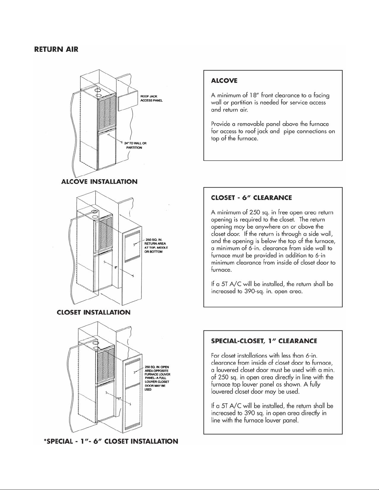
RETURN AIR
ALCOVE INSTRUCTION
The furnace may be installed free standing or in an
alcove with a free flow of air back to the furnace. A
minimum of 18” shall be provided at the front for
return air and service access.
CLOSET INSTALLATION – 6 in.
Note: If return air is through a side wall, there must
be a minimum of 6-in. clearance from side wall to
furnace in addition to 6-in. minimum clearance from
inside of closet door to front of furnace.
If a louvered door complying with the minimum air
requirements is used, the front clearance my be reduced to
1”.
CLOSET INSTALLATIONS
Additional Requirements
Concerning under floor or ceiling return air systems,
the following item (1 – 10) must be adhered to:
1. The return-air opening into the closet, regardless
of location, is to be sized not less than specified
on the appliance rating plate.
2. If the return-air opening is located in the floor of
the closet (versus the vertical front or side wall),
the opening is to be provided with means to
prevent its inadvertent closure by a flat object
placed over the opening.
3. The cross-sectional area of the return system
(when located in the floor or ceiling of the
manufactured home) leading into the closet is to
be not less than that of the opening specified on
the appliances rating plate.
4. The total free area of openings in the floor or
ceiling registers serving the return-air duct
system is to be not less than 150% of the size
opening specified on the appliance rating plate.
At least one such register is to be located where
the likelihood of its being covered by carpeting,
boxes, and other objects is minimized.
5. Materials located in the return duct system have
a flame spread classification of 200 or less.
6. Non-combustible pans having one-inch upturned
flanges are located beneath openings in the floor
return duct system.
7. Wiring materials located in the return d uct system
conform to Article 300-22 (B&C) of the National
Electric Code, ANSI / NFPA-70.
8. Gas piping is not run in or through the return duct
system.
9. The negative pressure in the closet, as determined by
test with the air-circulating fan operating at high
heating speed and the closet door closed, is to be not
more negative than minus 0.05-inch water column.
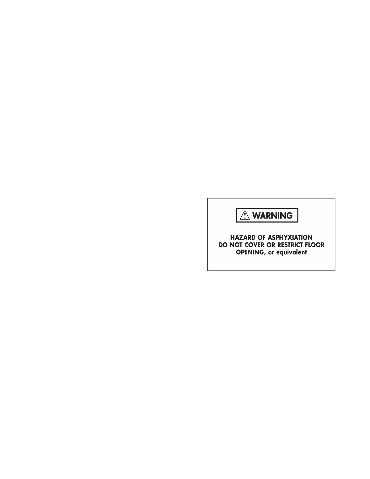
10. For floor return systems, the manufactured home
manufacturer or installer shall affix a prominent
warning where it is easily read when the closet door
is open.
The marking shall read:
Heat Controller, Inc. Jackson, MI 49203 MGD Installation Instructions 4
Page 5
MGD Series Gas Furnace Installation Instructions
Heat Controller, Inc. Jackson, MI 49203 MGD Installation Instructions 5
Page 6

MGD Series Gas Furnace Installation Instructions
Heat Controller, Inc. Jackson, MI 49203 MGD Installation Instructions 6
Page 7

MGD Series Gas Furnace Installation Instructions
SEALED COMBUSTION ROOF JACK – (REQUIRED)
Heat Controller, Inc. Jackson, MI 49203 MGD Installation Instructions 7
Page 8

MGD Series Gas Furnace Installation Instructions
CUTTING ROOF JACK OPENING
A proper installation of the roof jack requires that
openings in roof and ceiling be on the same vertical
centerline as the furnace flue collar. See FIG. 1
Mark the center point on the ceiling and scribe a 4” radius
(8” diameter) around this mark. If furnace is in place
during this step, cover the furnace and flue opening to
prevent debris from entering flue.
INSTALLING ROOF JACK
The roof jack body should be secured to the furnace
before the roof flashing is secured to the roof.
1. Insert roof jack body into opening in the roof.
2. From above, canter the roof jack body aligning with
the furnace collar.
3. From inside the home, pull down 4-3/16” D flue pipe
seating the pipe fully and firmly over the furnace flue
collar.
4. Next pull down the 7” D combustion air pipe seating
it over the mating furnace collar. Rotate the
combustion air pipe lining up to the screw hole on the
7” collar.
5. Check and make sure the combustion air pipe is fully
seated. Then drive a # 10 sheet metal screw, attaching
pipe firmly to furnace collar.
6. Install optional ceiling trim ring, 90-TRM-RNG
7. On the roof, caulk liberally under the roof jack
flashing.
8. Drive nails or screws through the flashing onto the
roof surface about 1 – 11/2” apart. Caulk again to
ensure a leak tight joint.
9. Install roof jack crown and fasten to roof jack body
with three (3) screws (provided) using pre-punched
holes.
.
INSTALLATION IN SNOW REGIONS
When the combustion air inlet to the roof jack is
blocked with snow, the furnace will not operate
properly due to the depleted combustion air supply.
Therefore, if the furnace will be located in regions where
snow accumulation on the roof exceeds 7” or in H.U.D.
Snow Load Zones, a roof jack extension – Part5 No. 90OUTXT16-AL is recommended.
ROOF JACK ON HI-PITCH ROOF
To install the RJS (3/12) Series Roof Jack on roofs which
have a slope between 4.5/12 – 6/12, install a Part No. 90RJS56 Roof Saddle, FIG. J. The combined assembly of
the RJS Roof Jack and Roof Saddle will conform to the
higher roof pitch. If roof pitch is greater than 6/12, field
fabricate a suitable adapter, or consult with factory.
Heat Controller, Inc. Jackson, MI 49203 MGD Installation Instructions 8
Page 9

MGD Series Gas Furnace Installation Instructions
CONNECT POWER SUPPLY
1. Remove the furnace control panel cover.
2. Insert 115 V wiring through a strain relief
bushing on the left side of the furnace.
3. Connect the HOT wire to the black pigtail lead;
connect the NEUTRAL wire to the WHITE
pigtail lead. Secure the connections with suitable
wire nuts and wrap with electrical tape. Refer to
Wiring Diagram on Pg. 11 for connections.
4. Connect the GROUND wire to a grounding screw
in the control panel.
5. Reinstall and secure the control panel cover with
screws.
Heat Controller, Inc. Jackson, MI 49203 MGD Installation Instructions 9
Page 10

MGD Series Gas Furnace Installation Instructions
GAS PIPE AND TUBING-MIN SIZES
MODEL TYPE LENGTH PIPE TUBING
MGD OF SIZE SIZE
GAS (FT.) (IN.) (IN. OD)
to 20 3/8 5/8
Natural to 60 1/2 -
60 to 70 - 3/4
to 40 3/8 Propane to 70 - 5/8
to 80 1/2 to 20 - 5/8
to 50 1/2 Natural to 60 - 3/4
75 to 80 3/4 -
to 30 3/8 Propane to 60 - 5/8
to 80 1/2 to 40 1/2 3/4
Natural to 50 - 3/4
90 to 30 3/8 Propane to 40 - 5/8
to 60 1/2 3/4
Heat Controller, Inc. Jackson, MI 49203 MGD Installation Instructions 10
Page 11

MGD Series Gas Furnace Installation Instructions
WIRING DIAGRAM, MGD
Heat Controller, Inc. Jackson, MI 49203 MGD Installation Instructions 11
Page 12

MGD Series Gas Furnace Installation Instructions
REPLACEMENT PARTS
Heat Controller, Inc. Jackson, MI 49203 MGD Installation Instructions 12
Page 13

MGD Series Gas Furnace Installation Instructions
MGD Gas Furnace Parts List
ITEM NO. USED ON FURNACE MODEL PART NO. QTY DESCRIPTION
1 All R68DD0010 1 Pressure Switch, -0.20 N.O.
2 All R71CA0006 2 ft. Silicon Tubing
3 All R68CA0005 1 Limit Switch, Manual, Upper-180F
4 All R86GF0050 1 Boost Blower Assembly, w/ Air Orifices
5 All R68GF0001 1 Integrated Control Board, HSI
6 All R68GF0006 1 Gas Valve for HSI Electric Ignition
7 All R68BKN007 1 Valve Bracket & Orifice Holder
MGD60 R86GF0051 1 Heat Exchanger & Gaskets
8
MGD75, 90 R86GF0052 1 Heat Exchanger & Gaskets
9 All R68GF0004 1 Flame Sensor
10 All R68DD0009 1 System Switch - SPST
11 All R68GF0002 1 Transformer (115V-24V, 40VA)
12 All R68CA0004 1 Limit Switch - Open 140 F - Close 110 F
13 All R86GF0054 1 Burner Assembly
14 All R68GF0005 1 Hot Surface Igniter
15 All R76AA0002 2 Filter (16" X 20" X 1")
16 All R86GF0055 1 Door Panel - Upper
17 All R86GF0143 1 Door Panel - Lower
MGD60/90-E3A R65GF0002 1 Motor - 1/3 HP
18
19 MGD60/90-E5A R86GF0056 1 Motor Mount Assembly
20
21 All R69AB0001 1 Blower Wheel - 10 x 8
30 All R86GF0058 4 Door Latch, Set
32
33 All R87NNE001 1 Filter Retainer Bracket
MGD60/90-E5A R65GF0003 1 Motor - 3/4 HP
MGD60/90-E3A R68DE0002 1 Capacitor - 15/370M
MGD60/90-E5A R68DE0003 1 Capacitor - 25/370V
MGD60 (Natural Gas) 72AG-144 1 Main Burner Orifice - #27
MGD75 (Natural Gas) 72AG-166 1 Main Burner Orifice - #20
MGD90 (Natural Gas) 72AG-177 1 Main Burner Orifice - #16
MGD60 (Propane) 72AG-089 1 Main Burner Orifice - #43
MGD75 (Propane) 72AG-101 1 Main Burner Orifice - #38
MGD90 (Propane) 72AG-110 1 Main Burner Orifice - #35
Heat Controller, Inc. Jackson, MI 49203 MGD Installation Instructions 13
Page 14

MGD Series Gas Furnace Installation Instructions
Reference: NFPA No. 54, ANSI Z 223.1 National Fuel Gas Code
Table shows 4% Input Reduction per 1,000 feet elevation
For Canadian High Altitude (2,000-4,500 feet), reduce gas pressure to burner manifold (manifold Ps.) to 3.0” W.C. and 9.0” W.C. for LP (Propane) Gas
Heat Controller, Inc. Jackson, MI 49203 MGD Installation Instructions 14
 Loading...