

Page 1
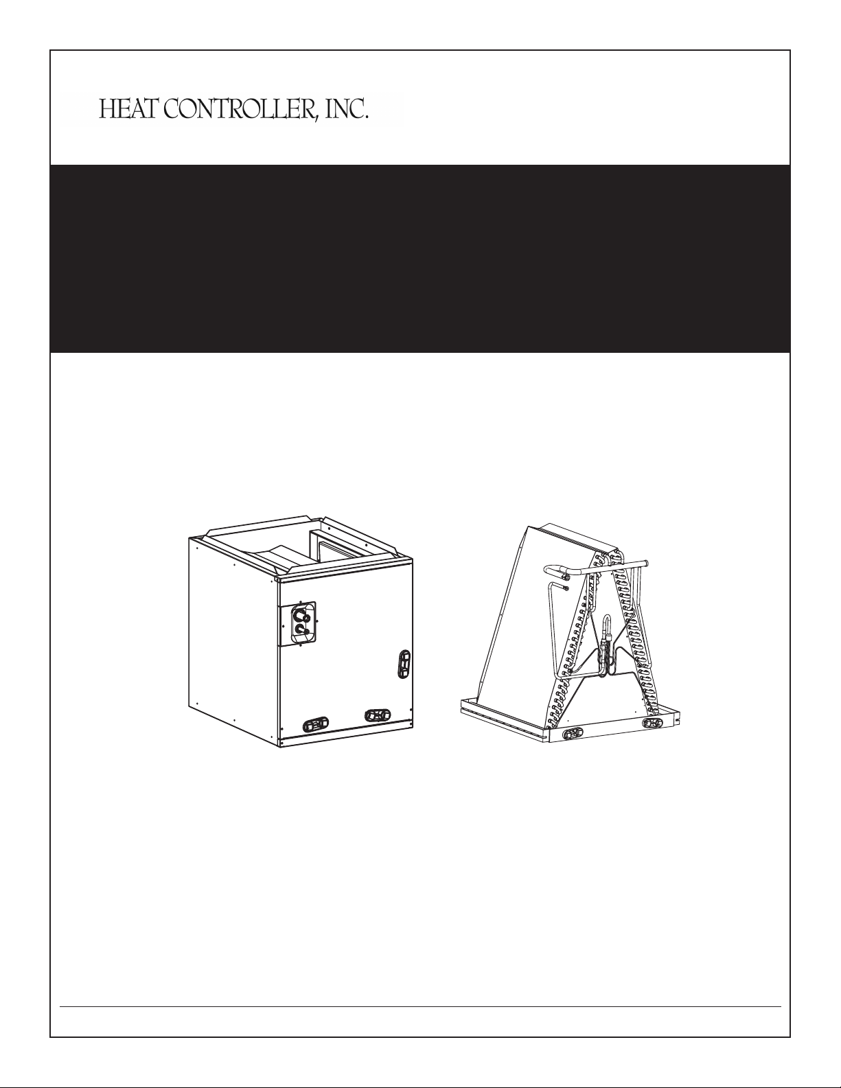
INSTALLATION INSTRUCTIONS
FEATURING R-410A OR R-22 REFRIGERANT
Multi-Position Cased and Uncased Coils for
Cooling / Heat Pumps
INSTALLATION
INSTRUCTIONS
Multi-Position
Cased & Uncased Coils for
Cooling and Heat Pumps
Heat Controller, Inc. • 1900 Wellworth Ave. • Jackson, MI 49203 • (517)787-2100 • www.heatcontroller.com
MDG Series
1.5 to 5 Ton
CDG Series
1.5 to 5 Ton
Page 2

Cased/Uncased Coils INSTALLATION INSTRUCTIONS Heat Controller, Inc.
Table of Contents
1.0 MODEL NOMENCLATURE .....................................................................................2
2.0 SAFETY ...................................................................................................................3
3.0 GENERAL .................................................................................................................4
3.1 CODES & REGULATIONS ...............................................................................................4
3.2 INSPECTION UPON UNIT ARRIVAL ................................................................................4
3.3 CLEARANCES ..................................................................................................................4
3.4 UNIT DIMENSION AND COMPONENT LOCATION .........................................................5
4.0 INSTALLATION INSTRUCTIONS .............................................................................7
4.1 REPLACEMENT PARTS ..................................................................................................7
4.2 PRE-INSTALLATION INSTRUCTIONS .............................................................................7
4.3 INSTALLATION AND TRAP CONNECTION .....................................................................7
5.0 DRAIN APPLICATION ..............................................................................................8
5.1 CONDENSATE DRAIN PIPING ........................................................................................8
5.2 PLASTIC DRAIN PAN INSTALLATION .............................................................................8
6.0 REFRIGERANT CONNECTIONS ...........................................................................10
6.1 FLOWRATOR PISTON CHANGE ...................................................................................10
LIST OF FIGURES AND TABLES
Fig.1 CASED DIMENSIONS AND COMPONENT LOCATION ..................................5
Fig.2 UNCASED DIMENSIONS AND COMPONENT LOCATION ............................6
Fig.3 INSTALLATION AND DRAIN CONNECTIONS ................................................7
Fig.4 UNCASED COIL ...............................................................................................8
Fig.5 DRAIN LINE INSTALLATION ...........................................................................9
Fig.6 DRAIN PIPE ROUTING ....................................................................................9
Fig.7 FLOWRATOR PISTON CHANGE ..................................................................10
TABLE 1 FLOWRATOR PISTON SIZE CHART ......................................................11
1
Page 3
Heat Controller, Inc. INSTALLATION INSTRUCTIONS Cased/Uncased Coils
1.0 Model Nomenclature
C D G 18 F A - A
C = Uncased Coil
V = Vertical Cased Coil
M = Multi Postion Cased Coil
Design Series
R-410A
Refrigerant
A = Revision
Code
A = 14 1/2" Wide Cabinet
B = 17 1/2" Wide Cabinet
C = 21" Wide Cabinet
D = 24 1/2" Wide Cabinet
F = Flowrater (Piston)
T = TXV
18 = 18,000 BTUH
24 = 24,000 BTUH
30 = 30,000 BTUH
36 = 36,000 BTUH
42 = 42,000 BTUH
48 = 48,000 BTUH
60 = 60,000 BTUH
NOTE: Not all model congurations are available. The nomenclature exists for
future product line development. Consult your local distributor or Heat
Controller’s customer service department regarding available options.
2
Page 4
Cased/Uncased Coils INSTALLATION INSTRUCTIONS Heat Controller, Inc.
2.0 Safety
When you see the symbols below on labels or in manual, be alert to the potential or immediate hazards
of personal injury, property and/or product damage. It is the owner’s or installer’s responsibility to comply
with all safety instructions and information accompanying these symbols.
Warning
This is a safety alert symbol indicating a potential hazardous situation, which could
result in personal injury, property and/or product damage or death.
Caution
This is a safety alert symbol indicating a potential hazardous situation, which could
result in moderate personal injury, and/or property and product damage.
Warning
Disconnect all power to the unit before starting any service and maintenance. Failure to
do so could cause severe electrical shock resulting in personal injury or death.
Warning
Installation or servicing of this unit can be hazardous due to parts, components and
system pressure. Qualied and proper trained service personnel should perform
installation and repair. Failure to do so could cause severe electrical shock resulting in
personal injure or death.
3
Page 5

Heat Controller, Inc. INSTALLATION INSTRUCTIONS Cased/Uncased Coils
3.0 General
The unit can be positioned for bottom return air in the upow position, left and right return in the horizontal position, top return in downow position.
3.1 Codes & Regulations
This product is designed and manufactured to comply with national codes. Installation in accordance with
such codes and/or prevailing local codes/regulations is the responsibility of the installer. The manufacturer assumes no responsibility for equipment installed in violation of any codes or regulations.
The United States Environmental Protection Agency(EPA) has issued various regulations regarding the
introduction and disposal of refrigerants. Failure to follow these regulations may harm the environment
and can lead to the imposition of substantial nes. Should you have any questions please contact the
local ofce of the EPA.
3.2 Inspection Upon Unit Arrival
As soon as unit is received, it should be inspected for possible shipping damage during transportation. It
is carrier’s responsibility to cover the cost of shipping damage. Manufacturer or distributor will not accept
a claim for any transportation damage.
3.3 Clearances
Clearances should be provided for the following during installation
a.Maintenance and service access, including coil cleaning and coil assembly removal
b.Refrigerant piping and connections
c.Condensate drain line
4
Page 6

Cased/Uncased Coils INSTALLATION INSTRUCTIONS Heat Controller, Inc.
3.4 Unit Dimension and Component Location
A
19''
VAPOR LINE CONNECTION
COPPER (SWEAT)
LIQUID LINE CONNECTION
COPPER (SWEAT)
COIL ACCESS
PANEL
H
HORIZONTAL DRAIN
CONNECTION
AUXILIARY DRAIN CONNECTION
3/4'' NPT FEMALE PIPE THREAD
20''
W1
21''
W
PRIMARY DRAIN CONNETION
3/4'' NPT FEMALE PIPE THREAD
Fig. 1: Cased Dimensions
and Component Location
Dimensional Data
“H”
Model No.
Height in. [mm]
MDG18FA-A 20” [508] 14 1/2” [368] 13” [330] 13 1/2” [343] 42 [19.1] 45 [20.5]
MDG18FB-A 20” [508] 17 1/2” [445] 16” [407] 16 1/2” [419] 47 [21.5] 50 [23]
MDG24FA-A 20” [508] 14 1/2” [368] 13” [330] 13 1/2” [343] 44 [20.1] 47 [21.5]
MDG24FB-A 20” [508] 17 1/2” [445] 16” [407] 16 1/2” [419] 49 [22.2] 52 [23.8]
MDG30FA-A 20” [508] 14 1/2” [368] 13” [330] 13 1/2” [343] 44 [20.1] 47 [21.5]
MDG30FB-A 20” [508] 17 1/2” [445] 16” [407] 16 1/2” [419] 49 [22.4] 53 [24]
MDG36FA-A 26” [660] 14 1/2” [368] 13” [330] 13 1/2” [343] 57 [26] 61 [27.7]
MDG36FB-A 26” [660] 17 1/2” [445] 16” [407] 16 1/2” [419] 60 [27.3] 64 [29.2]
MDG36FC-A 26” [660] 21” [533] 19 1/2” [495] 20” [508] 64 [28.9] 68 [31]
MDG42FB-A 30” [762] 17 1/2” [445] 16” [407] 16 1/2” [419] 70 [31.9] 75 [34]
MDG42FC-A 30” [762] 21” [533] 19 1/2” [495] 20” [508] 72 [32.6 ] 77 [34.8]
MDG42FD-A 30” [762] 24 1/2” [622] 23” [597] 23 1/2” [597] 75 [34.1] 80 [36.5]
MDG48FB-A 30” [762] 17 1/2” [445] 16” [407] 16 1/2” [419] 78 [35.6] 83 [37.8]
MDG48FC-A 30” [762] 21” [533] 19 1/2” [495] 20” [508] 83 [37.8] 88 [40]
MDG48FD-A 30” [762] 24 1/2” [622] 23” [597] 23 1/2” [597] 87 [39.4] 92 [41.8]
MDG60FC-A 30” [762] 21” [533] 19 1/2” [495] 20” [508] 83 [37.9] 88 [40]
MDG60FD-A 30” [762] 24 1/2” [622] 23” [584] 23 1/2” [597] 87 [39.4] 92 [41.8]
“W”
Width in. [mm]
“A”
Width in. [mm]
W1 Width
in. [mm]
Unit Weight
lbs. [kg]
Shipping Wt
lbs. [kg]
5
Page 7

Heat Controller, Inc. INSTALLATION INSTRUCTIONS Cased/Uncased Coils
TOP AIR STOP
VAPOR LINE CONNECTION
LIQUID LINE CONNECTION
AUXILIARY DRAIN CONNECTION
3/4'' NPT FEMALE PIPE THREAD
PRIMARY DRAIN CONNETION
3/4'' NPT FEMALE PIPE THREAD
H
D
W
Fig. 2: Uncased Dimensions and
Component Location
The Max. pressure resistance of evaporator is up to 2320 PSI (16MPa)
Dimensional Data
“H”
Model No.
CDG18FA-A 16 1/4” [412] 13 3/8” [339] 20 1/2” [521] 20 [9.2] 23 [10.6]
CDG18FB-A 16 3/4” [425] 16 3/8” [415] 20 1/2” [521] 25 [11.2] 28 [12.6]
CDG24FA-A 16 1/4” [412] 13 3/8” [339] 20 1/2” [521] 23 [10.4] 26 [11.8]
CDG24FB-A 16 3/4” [425] 16 3/8” [415] 20 1/2”” [521] 26 [11.8] 30 [13.5]
CDG30FA-A 16 1/4” [412] 13 3/8” [339] 20 1/2” [521] 23 [10.4] 26 [11.8]
CDG30FB-A 16 3/4” [425] 16 3/8” [415] 20 1/2” [521] 26 [11.8] 30 [13.5]
CDG36FA-A 22 3/4” [578] 13 3/8” [339] 20 1/2” [521] 30 [13.8] 34 [15.5]
CDG36FB-A 22 5/8” [576] 16 3/8” [415] 20 1/2” [521] 31 [14.3] 36 [16.2]
CDG36FC-A 22 1/2” [571] 19 3/8” [504] 20 1/2” [521] 32 [14.9] 37 [17]
CDG42FB-A 26 11/16” [678] 16 3/8” [415] 20 1/2” [521] 35 [15.9] 40 [18]
CDG42FC-A 26 9/16” [674] 19 7/8” [504] 20 1/2” [521] 37 [16.8] 42 [19]
CDG42FD-A 26 1/8” [664] 23 3/8” [593] 20 1/2” [521] 39 [17.6] 44 [20]
CDG48FB-A 26 7/8” [682] 16 3/8” [415] 20 1/2” [521] 46 [21] 51 [23.2]
CDG48FC-A 26 3/4” [679] 19 7/8” [504] 20 1/2” [521] 48 [21.8] 53 [24]
CDG48FD-A 28” [670] 23 3/8” [593] 20 1/2” [521] 50 [22.5] 55 [25]
CDG60FC-A 26 3/4” [679] 19 7/8” [504] 20 1/2” [521] 48 [21.8] 53 [24]
CDG60FD-A 28” [670] 23 3/8” [593] 20 1/2” [521] 50 [22.5] 55 [25]
Height in. [mm]
“W”
Width in. [mm]
“D”
Depth in. [mm] Weight lbs. [kg] Shipping Wt. lbs. [kg]
6
Page 8

Cased/Uncased Coils INSTALLATION INSTRUCTIONS Heat Controller, Inc.
Upflow Discharge
Downflow Discharge
4.0 Installation Instructions
4.1 Parts
Contact your distributor for authorized replacement parts.
4.2 Pre-Installation Instructions
Carefully read all instructions for installation prior to installing product. Make sure each step or procedure
is understood and any special considerations are taken into account before starting installation. Assemble all tools, hardware and supplies needed to complete the installation. Some items may need to be
purchased locally. Make sure everything needed to install the product is on hand before starting.
4.3 Installation and Trap Connection
See Fig .3 for coil installation and drain connection for vertical and horizontal applications.
Primary Drain
Alternate Drain
Furnace
Primary Drain
Upflow Drain
Connection
Vertical Drain Conditions
(All other drain connections should be plugged)
Furnace
Trapped
Furnace
Downflow Drain
Connection
Right Hand
Discharge
Alternate Drain
Left Hand
Discharge
Trapped
Horizontal Drain Conditions
(All other drain connections should be plugged)
Furnace
Fig. 3: Installation and Drain Connections
7
Page 9

Heat Controller, Inc. INSTALLATION INSTRUCTIONS Cased/Uncased Coils
5.0 Drain Applications
5.1 Condensate Drain Piping
Consult local codes for special requirements.
To provide extra protection from water damage, install an additional auxiliary drain pan, provided by
installer under the entire unit with a separate drain line. Manufacturer will not be responsible for any
damages due to the failure to follow these requirements.
5.2 Plastic Drain Pan Installation
Warning
Do not use the coil pan shipped with the unit on OIL furnaces or any application where the
temperature of the drain pan may exceed 275°F. A eld fabricated metal drain pan can be
used for these type of applications. Fallure to follow this warning may result in property
damage and/or personal injury.
If the uncased coil is to be installed on top of a gas furnace, allow enough space between the top of the
furnace and the bottom of the plastic coil drain pan to have a free ow of air. A minimum of 2.0” distance
from the top of the furnace and the bottom of the coil pan is required. The coil should be installed with
the line set and drain openings to the front of the furnace.
W
Fig. 4: Uncased Coil
W=Coil Pan Width + Insulation Thickness x2
Bottom flange detail
can be typical of the
details below
2''
GAS FURNACE
The coil drain pan has a primary and an optional secondary drain with 3/4” NPT female connections; use
either PVC or metal pipe and hand tighten to a torque of approximately 37 in-lbs. to prevent damage to
the drain pan connection. An insertion depth between 3/8'' to 1/2" inches (3-5 turns) should be expected
at this torque setting.
Use male 3/4” NPT threaded tting for outside connection and make sure the drain holes are not blocked.
Insulation may be needed for drain line to prevent sweating.
or
8
Page 10

Cased/Uncased Coils INSTALLATION INSTRUCTIONS Heat Controller, Inc.
Drain pan has two drain connections on each side to provide exibility of connection and drainage. Make
sure pan has proper pitch and plugged if second connection is not used.
It is highly recommended to use the secondary drain line to prevent overow when the primary drain is
plugged.
NOTE: Water coming from this line means the coil primary drain is plugged and needs clearing.
Install a trap in the drain line below the bottom of the drain pan (required). If using a copper drain line,
solder a short piece of pipe to the connector before installing a drain tting. DO NOT over torque the 3/4”
copper connector to the plastic drain connection. Use a wet rag or heatsink material on the short piece to
protect plastic drain pan, complete the drain line installation (Fig.5). Use (Fig.6) as a template for typical
drain pipe routing. This gure shows how to avoid interference with vent piping.
CONDENSATE DRAIN TRAP
DO NOT OPERATE UNIT WITHOUT
CONDENSATE DRAIN TRAP.
Unit
DO NOT OVERTIGHTEN DRAIN FITTING
UNIT MUST BE SLIGHTLY INCLINED
TOWARD DRAIN CONNECTION
Fig. 5: Drain Line Installation
secondary
primary
3"
3"
TO APPROVED DRAIN
secondary
primary
Fig. 6: Drain Pipe Routing
9
Page 11

Heat Controller, Inc. INSTALLATION INSTRUCTIONS Cased/Uncased Coils
6.0 Refrigerant Connections
To prevent refrigerant leak, use proper tools to ensure clean, burr-free cut.
Use brazing shield when welding close to the cabinet surface and wet rag to protect rubber grommet.
Brazing alloy should be at least 5% silver content.
6.1 Flowrator Piston Change
In most applications, there is no need to change the piston (orice). However, in some applications,
changing the piston size is required. If the application requires a different piston/owrator, change the
piston in the distributor of indoor coil before installing the coil. See Table 1 for orice size.
To change the piston, use following steps:
1. Remove cover panel.
2. Use Two wrenches.
Loosen one turn to release pressure. (High pressure gas)
3. After releasing pressure.
Loosen and carefully pull a part the two ttings to expose piston.
4. Remove factory installed piston and replace with recommended piston from Table 1 as shown in Fig.7.
5. Carefully reassemble assembly. (Hand tighten)
Be sure to use teon tape on thread for a complete seal.
6. Hand tighten and make sure assembly is properly connected and then torque to 10-30 ft/lb.
NOTE: Be careful not to bend tubing
LIQUID LINE
PISTON
NUT
(MOMENT:15±2N.m)
Fig. 7: Flowrator Piston Change
10
Page 12

Cased/Uncased Coils INSTALLATION INSTRUCTIONS Heat Controller, Inc.
Table 1: Flowrator Piston Size Chart
NOTE: Pistons are factory installed for use with RSG-1D series condenser. To use the
coil with a HRG-1D series heat pump, a piston change may be required. Refer to Table 1.
Condensing Unit
Model No.
RSG18S-1D
RSG18R-1D
RSG24S-1D
RSG24R-1D
RSG30S-1D
RSG30R-1D
RSG36S-1D
RSG42S-1D
RSG48S-1D
RSG60S-1D
HCI Indoor Coil
MDG18FA-A CDG18FA-A
MDG18FB-A CDG18FB-A
MDG24FA-A CDG24FA-A
MDG24FB-A CDG24FB-A
MDG30FA-A CDG30FA-A
MDG30FB-A CDG30FB-A
MDG36FA-A CDG36FA-A
MDG36FC-A CDG36FC-A
MDG42FB-A CDG42FB-A
MDG42FD-A CDG42FD-A
MDG48FB-A CDG48FB-A
MDG48FD-A CDG48FD-A
MDG60FC-A CDG60FC-A
MDG60FD-A CDG60FD-A
PISTON SIZECased Coil Uncased Coil
0.050
0.053
0.059
0.070MDG36FB-A CDG36FB-A
0.072MDG42FC-A CDG42FC-A
0.088MDG48FC-A CDG48FC-A
0.098
Heat Pump
Model No.
HRG18S-1D
HRG24S-1D
HRG30S-1D
HRG36S-1D
HRG42S-1D
HRG48S-1D
HCI Indoor Coil
PISTON SIZECased Coil Uncased Coil
MDG18FA-A CDG18FA-A
0.050
MDG18FB-A CDG18FB-A
MDG24FA-A CDG24FA-A
0.053
MDG24FB-A CDG24FB-A
MDG30FA-A CDG30FA-A
0.064
MDG30FB-A CDG30FB-A
MDG36FA-A CDG36FA-A 0.071
MDG36FB-A CDG36FB-A 0.066
MDG36FC-A CDG36FC-A 0.068
MDG42FB-A CDG42FB-A 0.079
MDG42FC-A CDG42FC-A 0.078
MDG42FD-A CDG42FD-A 0.080
MDG48FB-A CDG48FB-A 0.088
MDG48FC-A CDG48FC-A 0.092
MDG48FD-A CDG48FD-A 0.096
HRG60S-1D
MDG60FC-A CDG60FC-A 0.118
MDG60FD-A CDG60FD-A 0.111
11
Page 13

04/2011
 Loading...