

Page 1

INSTALLATION, OPERATION
& MAINTENANCE MANUAL
CCG / VCG / MCG Coils
Heat Controller • 1900 Wellworth Ave. • Jackson, MI 49203 • (517)787-2100 • www.heatcontroller.com
Page 2
CCG / VCG / MCG Coils Heat Controller
Safety Instruction
Potential safety hazards are alerted using symbol. The
symbol is used in conjunction with terms that indicate the
intensity of the hazard.
!
WARNING
This symbol indicates a potentially hazardous situation,
which if not avoided, could result in serious injury,
property damage, product damage or death.
!
CAUTION
This symbol indicates a potentially hazardous situation,
which if not avoided, may result in moderate injury or
property damage.
!
WARNING
Certied technicians or those individuals meeting
the requirements specied by NATE may use this
information. Property and product damage or
personal injury hazard may occur without such
background.
!
needed for successful installation of the unit prior to
beginning the installation.
Condensate Drain Preparation
An auxiliary drain pan must be provided by the installer
and placed under the entire unit with a separate drain
line that is properly sloped and terminated in an area
visible to the home owner. The auxiliary pans provide
extra protection to the area under the unit should the
primary and secondary drain plug up and overow. As
expressed in our product warranty; MANUFACTURER
WILL NOT BE BILLED FOR ANY STRUCTURAL
DAMAGES CAUSE BY FAILURE TO FOLLOW THIS
INSTALLATION REQUIRMENT. The drains from the
auxiliary drain pan must be installed according to the local
building codes.
!
CAUTION
The drain lines from the Auxiliary should NOT be
connected to the primary drain line of the coil.
!
WARNING
All power sources should be disconnected prior to
servicing. Failure to do so may cause personal injury or
property damage.
!
WARNING
Product designed and manufactured to permit installation
in accordance with local and national building codes.
It is the installer’s responsibility to ensure that product
is installed in strict compliance with national and local
codes. Manufacturer takes no responsibility for damage
(personal, product or property) caused due to installations
violating regulations.
Inspection
Upon receiving the product, visually inspect it for any
major shipping related damages. Shipping damages are
the carrier’s responsibility. Inspect the product labels to
verify the model number and options are in accordance
with your order. Manufacturer will not accept damage
claims for incorrectly shipped product.
!
WARNING
Do NOT install coils with plastic drain pans on any OIL or
DRUM type furnaces or applications where temperature
of the drain pan might exceed 260±5 ºF (126.6±5 ºC). A
metal pan should be specied in these applications.
Install cased coils with plastic drain pans on a level, at
surface. Incase of coils with metal drain pans slop the coil
¼” towards the drain. No such pitch is necessary in case
of plastic drain pans. Condensate drain lines must be
installed in accordance with local building codes.
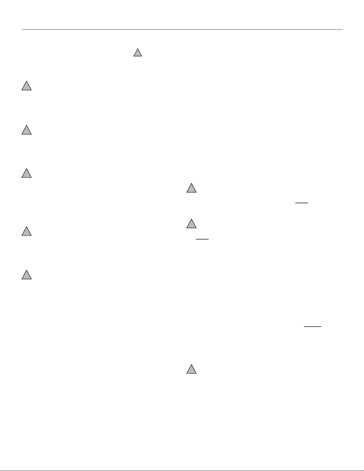
The drain lines must be installed with ¼” per foot pitch
to provide free drainage. A condensate trap MUST be
installed on the primary drain line to ensure proper
drainage of the condensate. The trap must be installed in
the drain line below the bottom of the drain pan. Figure 1
illustrates the typical drain trap installation
!
CAUTION
If the drain pan is constructed of nylon or plastic; use
Teon tape to connect the drain lines to the threads in the
drain pan. DO NOT USE SOLVENT BASED PIPE DOPE.
THIS WILL REDUCE THE LIFE OF THE PAN.
Installation Preparation
Read all the instructions in this guideline carefully while
paying special attention to the WARNING and CAUTION
alerts. If any of the instructions are unclear
clarify with certied technicians. Gather all the tools
2
Page 3
Heat Controller CCG / VCG / MCG Coils
CAUTION
Some Aspen coils may include a
Schrader valve on the suction manifold. Ensure that the
Schrader valve and valve core (where present) are
protected from heat to prevent leakage.
Metering Device
Aspen coils are available with two kinds of metering
devices a) flowrator or b) TXV. Instructions below are
separated in sections according to the metering device.
Ensure that the applicable section is thoroughly read
and understood.
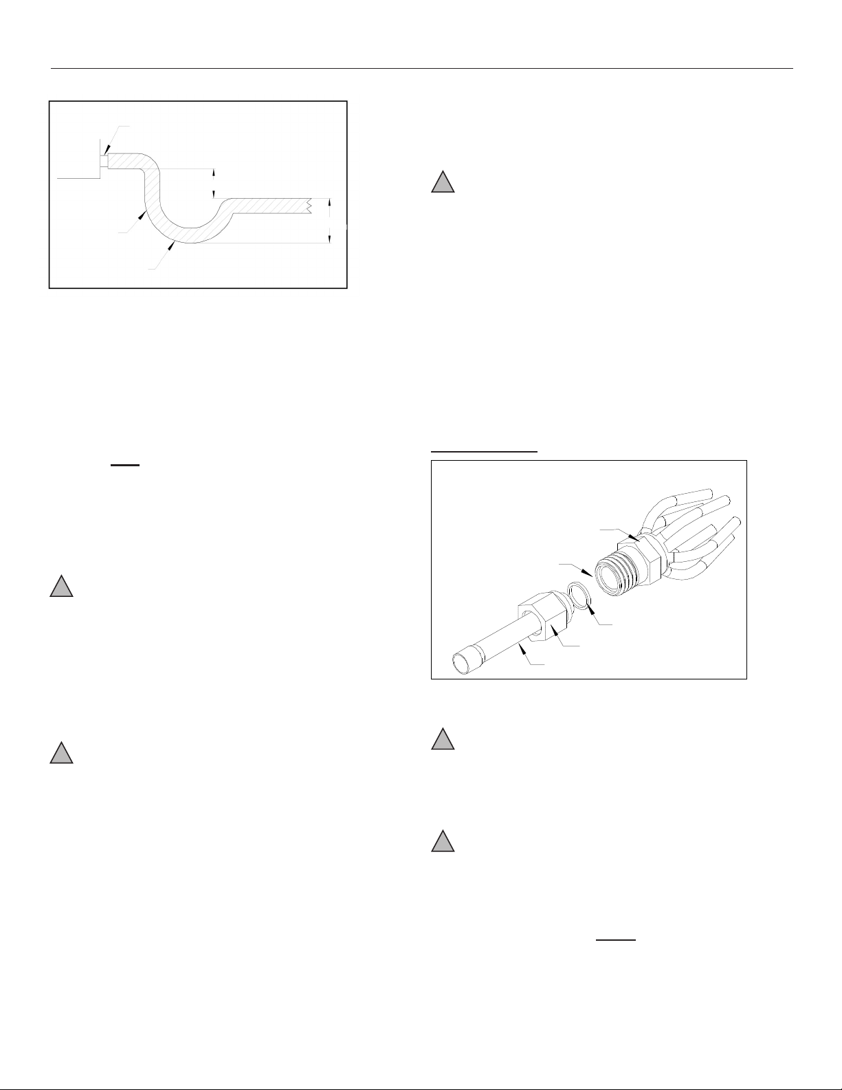
Flowrator Coils:
PISTON
DISTRIBUTOR
3/4"
TAIL PIECE
13/16" NUT
TEFLON O-RING
DRAIN
CONNECTION
UNIT
2” MINIMUM
FLEXIBLE
TUBING-HOSE
OR PIPE
A POSITIVE
LIQUID SEAL IS
REQUIRED
3” MINIMUM
Figure. 1. Typical drain line trap set up
The drain pan has primary and secondary drain
connections. If a secondary drain line is required it should
be run separately from the primary and should terminate in
a highly visible location. Condensate disposal through the
secondary drain line indicates that the primary drain line is
plugged and needs cleaning. If a secondary drain line will
not be provided plug the secondary drain. The red drain
plugs are NOT to be reused without plumbers tape or putty.
The drain line connectors should be hand tightened to a
torque of approximately 35-40 lb (4-5 turns).
Use of wet rags/quenching cloth is highly recommended
to prevent weld-related damages to the casing and
Schrader valve (if present).
!
CAUTION
Some coils may include a Schrader valve on the suction
manifold. Ensure that the Schrader valve and valve
core (where present) are protected from heat to prevent
leakage.
Metering Device
Coils are available with two kinds of metering devices a)
owrator or b) TXV. Instructions below are separated in
sections according to the metering device. Ensure that the
applicable section is thoroughly read and understood.
Flowrator Coils:
Coil Installation
!
WARNING
The coil was manufactured with dry nitrogen pre-charge.
Release the pressure through the Schrader valve test
port prior to installation. If holding pressure is not present,
return coil to distributor for exchange.
Clean coil ns with degreasing agent or mild detergent
and rinse ns clean prior to installation.
!
CAUTION
Coil should be installed on the discharge side of the furnace
The refrigerant line sizes should be selected according to
the recommendations of the outdoor unit manufacturer.
All connection joints should be burr free and clean. Not
removing burr and cleaning may increase chances of a
leak. It is recommended to use a pipe cutter to remove
the spun closed end of the suction line.
To avoid damage to grommets (where present); remove
these prior to brazing by sliding over the lines. Use a
quenching cloth or allow the lines to cool down before
reinstalling the grommets.
Figure. 2. Flowrator assy components
!
CAUTION
Use Piston sizes recommended by the outdoor unit
manufacturer whenever possible. The piston should be
sized according to the capacity of the outdoor unit.
!
WARNING
Failure to install the proper piston can lead to poor system
performance and possible compressor damage.
During some installations a piston change may be
required. If so the installer MUST change the piston.
As stated earlier, use piston sizes recommended by
the outdoor unit manufacturer. If a sizing chart is not
available, use the piston size chart provided below to size
the required piston. The size of the piston is stamped on
the piston body. Use this chart when matching coil with an
outdoor unit with a different nominal capacity than the coil.
3
Page 4

CCG / VCG / MCG Coils Heat Controller
Outdoor
Capacity
12,000
0.041
N/A
18,000
0.055
0.049
24,000
0.059
0.055
30,000
0.068
0.059
36,000
0.074
0.068
42,000
0.080
0.074
48,000
0.084
0.080
60,000
0.092
0.089
TXV Coils:
WARNING
The sensing bulb and TXV body
MUST be protected from overheating during brazing.
The sensing bulb and TXV body must be covered using
a quench cloth or wet cloth when brazing. Pointing the
brazing flame away from the valve and sensing bulb
provide partial protection only.
Orifice Size–R22 Orifice Size-R410A
Table. 1. Piston Size Chart
Instruction for piston change
1. Turn the 13/16 nut once to release any residual
pressure in the coil.
2. After ensuring that the coil is free of any residual
pressure, disassemble the owrator body completely
using two wrenches. Distortion of the feeder tubes
SHOULD be avoided.
3. The wrench used to clasp the nut should be turned in
counter-clockwise direction to unscrew the nut.
9. Slide the grommet back to position to prevent air leakage.
TXV Coils:
!
WARNING
The sensing bulb and TXV body MUST be protected from
overheating during brazing. The sensing bulb and TXV
body must be covered using a quench cloth or wet cloth
when brazing. Pointing the brazing ame away from the
valve and sensing bulb provide partial protection only.
!
CAUTION
Ensure that the TXV selected is compatible with the
refrigerant used in the outdoor system (R22 or R410A).
TXV caps are painted green for R22 or pink for R410A.
In absence of color, the caps will be marked with the
compatible refrigerant.
!
CAUTION
The valves should be sized according to the capacity of
the outdoor unit. Failure to install the right valve can lead
to poor performance and possible compressor damage.
Pay close attention to the Teon O-ring. Be sure to
replace the O-ring to attain a proper seal. (The Teon
O-ring is located between the two halves of the owrator)
Pay close attention to the piston orientation. The pointed
end of the piston MUST go into the distributor body/
towards the coil. Failure to ensure this orientation will
cause the piston to be bypassed during operation which
might damage the outdoor unit.
4. Slide the 13/16 nut over the line set and separate the
two halves of the owrator.
!
CAUTION
5. Pull the piston out using a small wire or pick. Verify
the piston size (size is typically stamped on the body
of the piston). If a different piston size is required
by the outdoor unit manufacturer replace the piston
using the small wire provided with the piston kit.
!
CAUTION
6. Assemble the two halves correctly and ensure that the
white Teon O-ring is present between the two halves.
7. Slide the 13/16 nut onto the distributor body.
8. Tighten the nut to a torque of approximately 10-30 ftlbs. Do NOT over tighten the nut. This will hamper the
piston movement during operation.
TXV Bulb Mounting
The orientation and location of the TXV bulb has a major
inuence on the system performance.
!
CAUTION
Ensure that the TXV bulb is in direct contact with the
suction/vapor line. Gap between the bulb and tube
should be avoided. Failure to do so will impair the proper
functioning of the TXV valve.
It is recommended that the TXV bulb be installed parallel
to the ground (in a horizontal plane). The bulb position
should be above and between 4 o’clock and 8 o’clock.
Fig. 3 shows the recommended position for the TXV bulb
installation in the horizontal plane.
The TXV sensing bulb SHOULD be mounted using
the metal clamp provided. In order to obtain a good
temperature reading and correct superheat control, the
TXV sensing bulb must conform to ALL of the following
criteria:
1) The sensing bulb MUST be in direct and continuous
contact with the suction line
2) The sensing bulb should be mounted horizontally on
the suction line.
3) The sensing bulb MUST be in direct and continuous
contact with the suction line
4) The sensing bulb should be mounted horizontally on
the suction line.
4
Page 5
Heat Controller CCG / VCG / MCG Coils
When installing an expansion valve, it is not necessary
to remove all the access panels and slide the coil out of
the housing.
1) Disassemble the flowrator body using two
wrenches. Unscrew the body with a counter-
clockwise motion.
2) Replace the white Teflon seal in place (located
between the halves).
3) Remove the existing flowrator piston using a
small wire or pick.
4) Inspect the TXV box to confirm that the valve is
TXV BULB POSI TION
4 O'CLOCK OR
8 O'CLOCK
METAL STRAP
SUCTION/VAPOR LINE
Fig.3. Recommended location of the TXV bulb in a
horizontal orientation
5) The sensing bulb MUST be mounted above and
between the 4 and 8 o’clock position on the
circumference of the suction line.
6) The sensing bulb MUST be insulated from
outside air.
The mounting location and insulation guards THE
sensing bulb from false reading due to hot outside air or
liquid refrigerant formed inside the suction/vapor line.
As recommended earlier, the TXV sensing bulb should
be mounted in a horizontal plane in relation to the
suction/vapor line. However, in case such a mounting is
not feasible and the sensing bulb has to be mounted
vertically; then place the bulb as shown in Fig.4.
When installing an expansion valve, it is not necessary
to remove all the access panels and slide the coil out of
the housing.
1) Disassemble the flowrator body using two
wrenches. Unscrew the body with a counter-
clockwise motion.
2) Replace the white Teflon seal in place (located
between the halves).
3) Remove the existing flowrator piston using a
small wire or pick.
4) Inspect the TXV box to confirm that the valve is
compatible with the refrigerant in the system.
5) Remove the valve from the box and note the
location of the inlet side (threaded male port)
and the outlet side (female swivel nut port).
6) After ensuring that the white Teflon seal is still
in place inside the flowrator body, screw the
female swivel nut onto the flowrator body.
7) Place the attachment nut on the liquid line.
8) Braze the stub-out portion to the liquid line and
let cool.
WARNING
Do not attempt to touch the braze
joint while hot. Touching it may cause sever burns.
9) Remove the additional white Teflon seal ring
from the box and place on the shoulder just
inside the inlet port. Screw the nut attached to
the stub-out portion of the flowrator body onto
the inlet port of the TXV.
10) Tighten all connections taking care to use
proper back up.
Some Aspen coils come with a Schrader valve on the
suction line. If a Schrader port is present
11) Remove valve stem from the Schrader port
mounted on the suction line
12) Screw flare nut on TXV equalization tube in to
the Schrader valve stem
Typical expansion valve assembly is shown below in
Fig. 5.
CAUTION
Field – Installed Expansion Valve Coils
SUCTION/VAPOR LINE
Remove the valve identication sticker from the valve and
METAL STRAP
place it adjacent to the model number on unit name plate.
When installing an expansion valve, it is not necessary to
remove all the access panels and slide the coil out of the
housing.
TXV BULB POSI TION
4 O'CLOCK OR
8 O'CLOCK
Fig. 3. Recommended location of the TXV bulb in a
horizontal orientation
5) The sensing bulb MUST be mounted above and between the 4 and 8 o’clock position on the circumference of the suction line.
6) The sensing bulb MUST be insulated from outside air.
The mounting location and insulation guards THE sensing bulb from false reading due to hot outside air or liquid
refrigerant formed inside the suction/vapor line.
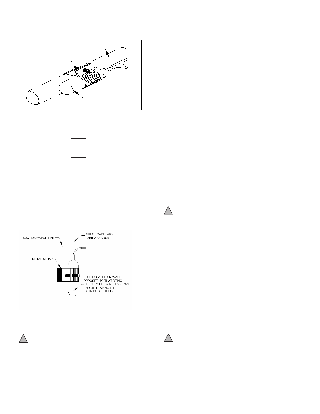
As recommended earlier, the TXV sensing bulb should be
mounted in a horizontal plane in relation to the suction/vapor line. However, in case such a mounting is not feasible
place the bulb as shown in Fig. 4.
Fig. 4. Figure showing the sensing bulb mounted in a
vertical orientation
!
CAUTION
If the TXV sensing bulb is mounted vertically; the capillary
and the sensing bulb has to be mounted vertically; then
MUST be directed upwards. The bulb must be mounted
on the wall opposite to that being directly hit by the refrigerant and oil leaving the distributor tubes.
1) Disassemble the owrator body using two wrenches.
Unscrew the body with a counter-clockwise motion.
2) Replace the white Teon seal in place (located between the halves).
3) Remove the existing owrator piston using a small
wire or pick.
4) Inspect the TXV box to conrm that the valve is compatible with the refrigerant in the system.
5) Remove the valve from the box and note the location
of the inlet side (threaded male port) and the outlet
side (female swivel nut port).
6) After ensuring that the white Teon seal is still in
place inside the owrator body, screw the female
swivel nut onto the owrator body.
7) Place the attachment nut on the liquid line.
8) Braze the stub-out portion to the liquid line and let
cool.
!
WARNING
Do not attempt to touch the braze joint while hot. Touching
it may cause sever burns.
9) Remove the additional white Teon seal ring from the
box and place on the shoulder just inside the inlet
port. Screw the nut attached to the stub-out portion of
the owrator body onto the inlet port of the TXV.
10) Tighten all connections taking care to use proper
back up.
Some coils come with a Schrader valve on the suction
line. If a Schrader port is present
11) Remove valve stem from the Schrader port mounted
on the suction line
12) Screw are nut on TXV equalization tube in to the
Schrader valve stem
Typical expansion valve assembly is shown below in Fig. 5.
!
CAUTION
Using a non-bleed expansion valve may require the use
of a hard-start kit. Follow the outdoor unit manufacturer’s
guidelines.
5
Page 6

CCG / VCG / MCG Coils Heat Controller
Note:
To set up a multi-position (CE) and or upflow/downflow
(CC) coils for downflow application, install a 3” wide by
16” long galvanized metal plates on the outside of the
coil, against the fins as shown in FIG.7.
WARNING
As mentioned elsewhere in this
document in an application involving oil furnace a metal
drain pan MUST be used. Coils installed on an oil
furnace must have a minimum of six inches clearance
between the top of the furnace and bottom of the drain
pan.
TXV BULB
DISTRIBUTOR
TEFLON O- RINGS
TAIL PIECE
Fig. 5. Components of a typical TXV assembly
Coil Application
Vertical
CCG (Uncased Coils), VCG (Cased Upow/ Downow)
and MCG (Multi-Position) can be installed in either an
upow or a downow application. Fig 6 shows the typical
conguration for the same.
Note:
To set up a multi-position (MCG) and or upow/downow
(VCG) coils for downow application, install a 3” wide by
16” long galvanized metal plates on the outside of the coil,
against the ns as shown in FIG.7.
!
WARNING
As mentioned elsewhere in this document in an
application involving oil furnace a metal drain pan MUST
be used. Coils installed on an oil furnace must have a
minimum of six inches clearance between the top of the
furnace and bottom of the drain pan.
!
CAUTION
When installing in conjunction with a gas furnace in a
vertical orientation, ensure that there is 2” gap between
the bottom of the drain pan and the outlet of the furnace.
Fig. 6. Typical Vertical Application of Coils
!
CAUTION
To position the coil on a furnace:
1) Locate the air outlet of the furnace
2) Position the coil over/under the outlet after adjusting
the anges accordingly.
3) Place ductwork over the casing anges
3" X 16" Metal Plate
Fig. 7. Metal Plate location for a Downow/
Counterow Application
Horizontal
Multi-position coils (MCG) are shipped from the factory
such that they can be installed in both vertical and
horizontal application without any change to the coil.
Cautions, warnings and instructions to install these in the
vertical application are mentioned in the relevant section
above. When installing these coils in the horizontal
application, the details mentioned in this section must be
followed.
Fig. 8 shows horizontal right and left application of
the CE coils.
!
CAUTION
Coils are shipped from the factory for specic horizontal
applications viz. horizontal right or horizontal left. Installer
must ensure that the coil is installed in the orientation for
which it was intended (horizontal drain pan side down).
Failure to follow these instructions might lead to property
and equipment damage.
Multiposition (MCG) coils come equipped with a horizontal
drain pan (Plastic/Metal). The plastic drain pan is
protected using a metal clip at the apex of the coil.
6
Page 7

Heat Controller CCG / VCG / MCG Coils
SUPERHEAT AND SUBCOOL CHART
Outdoor Temp
°F D.B.
Superheat °F Subcooling °F
Min Nom Max Min Nom Max
65 35 40 45 12 14 15
70 31 35 39 12 14 15
75 26 30 34 12 14 15
80 22 25 28 12 14 15
85 17 20 23 12 14 15
90 13 15 17 12 14 15
95 8 10 12 12 14 15
100 4 5 6 12 14 15
When installing in horizontal applications with airow
directed into the apex ensure the presence of a metal
plate as shown in Fig 8. Absence of the plate in such
an application might increase the chances of property
damage due to re or electric hazard.
System Charging
!
CAUTION
An improperly charged system might cause degradation
in system performance and may damage the compressor.
After installation of the coil, refer to the outdoor unit
manufacturer for charging techniques and amount of
charge.
1) For a downow application do NOT exceed 350 cfm/
ton of airow
2) Flowrator coils – Add refrigerant until the superheat
measured at the outdoor unit suction/vapor line
matches the superheat from the chart below
3) Expansion valve coils – Add refrigerant until the
subcooling measured at the outdoor unit liquid line
matches the subcooling recommendation of the
outdoor manufacturer (typically 7º – 10º F). If chart is
unavailable refer to chart below
Metal Bracket
Fig. 8. Horizontal right application of a MCG coil
SUPERHEAT AND SUBCOOL CHART
Outdoor Temp
°F D.B. (°C)
65 (18.3) 35 (-1.7) 40 (4.4) 45 (7.2) 12 (-11.1) 14 (-10) 15 (-9.4)
70 (21.1) 31 (-0.6) 35 (1.7) 39 (3.9) 12 (-11.1) 14 (-10) 15 (-9.4)
75 (23.9) 26 (-3.3) 30 (-1.1) 34 (1.1) 12 (-11.1) 14 (-10) 15 (-9.4)
80 (26.7) 22 (-5.6) 25 (-3.9) 28 (-2.2) 12 (-11.1) 14 (-10) 15 (-9.4)
85 (29.4) 17 (-8.3) 20 (-6.7) 23 (-5) 12 (-11.1) 14 (-10) 15 (-9.4)
90 (32.2) 13 (-10.6) 15 (-9.4) 17 (-8.3) 12 (-11.1) 14 (-10) 15 (-9.4)
95 (35.0) 8 (-13.3) 10 (-12.2) 12 (-11.11) 12 (-11.1) 14 (-10) 15 (-9.4)
100 (37.8) 4 (-15.6) 5 (-15) 6 (-14.4) 12 (-11.1) 14 (-10) 15 (-9.4)
Min. Nom. Max. Min. Nom. Max.
Superheat °F (°C) Subcooling°F (°C)
7
Page 8

CCG / VCG / MCG Coils Heat Controller
'XHWRRQJRLQJSURGXFWLPSURYHPHQWVVSHFLILFDWLRQVDQGGLPHQVLRQVDUH
VXEMHFWWRFKDQJHDQGFRUUHFWLRQZLWKRXWQRWLFHRULQFXUULQJREOLJDWLRQV'HWHUPLQLQJWKH
DSSOLFDWLRQDQGVXLWDELOLW\IRUXVHRIDQ\SURGXFWLVWKHUHVSRQVLELOLW\RIWKHLQVWDOOHU
$GGLWLRQDOO\WKHLQVWDOOHULVUHVSRQVLEOHIRUYHULI\LQJGLPHQVLRQDOGDWDRQWKHDFWXDOSURGXFW
SULRUWREHJLQQLQJDQ\LQVWDOODWLRQSUHSDUDWLRQV
,QFHQWLYHDQGUHEDWHSURJUDPVKDYHSUHFLVHUHTXLUHPHQWVDVWRSURGXFWSHUIRUPDQFH
DQGFHUWLILFDWLRQ$OOSURGXFWVPHHWDSSOLFDEOHUHJXODWLRQVLQHIIHFWRQGDWHRIPDQXIDFWXUH
KRZHYHUFHUWLILFDWLRQVDUHQRWQHFHVVDULO\JUDQWHGIRUWKHOLIHRIDSURGXFW
7KHUHIRUHLWLVWKHUHVSRQVLELOLW\RIWKHDSSOLFDQWWRGHWHUPLQHZKHWKHUDVSHFLILF
PRGHOTXDOLILHVIRUWKHVHLQFHQWLYHUHEDWHSURJUDPV
:HOOZRUWK$YH-DFNVRQ0,3KZZZKHDWFRQWUROOHUFRP
6/2014
8
 Loading...