

Page 1
INSTALLATION &
OPERATION MANUAL
Glass Panel
Convection Heater
Portable or Wall Mount
IRGPH15B
For Indoor Use only
Heat Controller • 1900 Wellworth Ave. • Jackson MI 49203 • 517-787-2100 • www.heatcontroller.com
Page 2
WARNINGS
This electric appliance produces convection heat and failure to
follow warnings and instructions can cause a re or injury.
READ AND SAVE THESE INSTRUCTIONS!
WARNING
FIRE OR EXPLOSION HAZARD
• Failure to follow safety warnings exactly could
result in serious injury or property damage.
• For indoor use only.
• Do not use the heater close to furniture, curtains or
other ammable items. Allow at least 36 inches (1
meter) between the heater and ammable items.
• Do not cover or otherwise obstruct the heater.
• Do not cover or obstruct the heater outlet slots on
the top of the unit or the air inlet slots on the bottom
of the unit.
• Do not use in bathrooms, laundry rooms or other
areas that are damp or have standing water.
WARNING
PERSONAL INJURY HAZARD
• Do not touch the heater during operation. Burn or
scald injury could result.
• Keep children away from the heater. Never leave
an unsupervised child near the heater.
• Because of injury risk, the heater should be
operated only by individuals knowledgeable about
the operation and familiar with the warnings and
cautions listed in this manual.
• Because of injury risk, this heater is not intended
for use by persons with reduced physical, sensory
or mental capabilities.
WARNING
PERSONAL INJURY HAZARD–SERVICE
• To avoid property damage, personal injury or death
due to electrical shock, do not service the unit
without rst unplugging the unit from the wall outlet
and allowing adequate time for the unit to cool down.
• Service must be performed only by a qualed
service technician.
• Do not use the heater if the power cord is
damaged. Contact an authorized servicer or
electrician to replace the cord prior to use.
WARNING
INSTALLATION & USE
To avoid property damage, personal injury or death
due to electrical shock, follow all the instructions in
this Installation and Operation manual.
• All local, regional and national electric codes and
local construction codes must be observed in the
installation of the heater.
• The power outlet must be properly polarized and
grounded. Use of a ground fault circuit interrupter
(GFCI) is always recommended.
• Be sure the voltage listed on the heater’s
nameplate is the same as the voltage at the
installation site.
• The room where the heater is being used should
have a working smoke detector installed.
• Do not place the heater behind a door or other
obstacle and operate it.
• Do not place the power cord under a carpet or rug.
• Wall mount option: do not alter power cable.
• Remove the plug from the power outlet and wait
until the heater is sufciently cool before cleaning it.
CAUTION•
• Use an extension cord with extreme caution,
making sure the extension cord is rated to handle
the heater’s amp and watt load.
• Use extreme caution whenever the heater is left
operating and unattended.
• Wall mount option: Do not install the heater
immediately below or in front of an electrical wall
outlet.
• Do not use a timer or other device that automatically
turns on the unit.
• Do not use the heater with an external voltage
regulator such as a dimmer or speed controller.
• Unplug the heater from the power source when not
in use.
2
Page 3
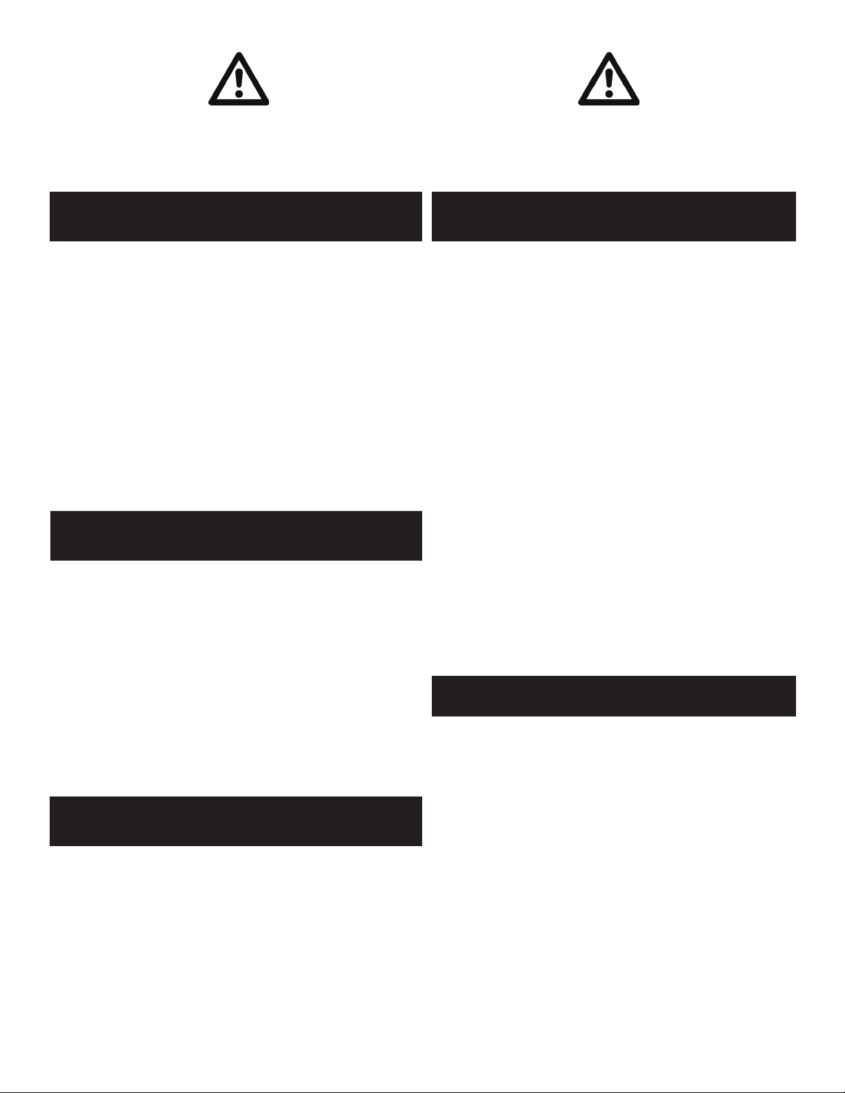
FIXED WALL MOUNT LOCATION
• This heater is designed for indoor use only.
• Do not locate the heater in front of or below a xed
socket outlet.
• Comply with the minimum clearance in front of or
below a xed socket outlet as shown in Figure 1.
• Do not install the heater where a draft is likely to
affect the temperature setting.
FIXED WALL MOUNT OPTION–INSTALLATION
INSTALL ON THE WALL
MINIMUM CLEARANCES
10" (250mm)
2
18" (450mm)
2
FIG. 1
2
6" (150mm)
STEP 3
STEP 1 STEP 2
Refer to directions
on following page
STEP 4
3
Page 4

Owner’s Manual Glass Panel Heater Heat Controller
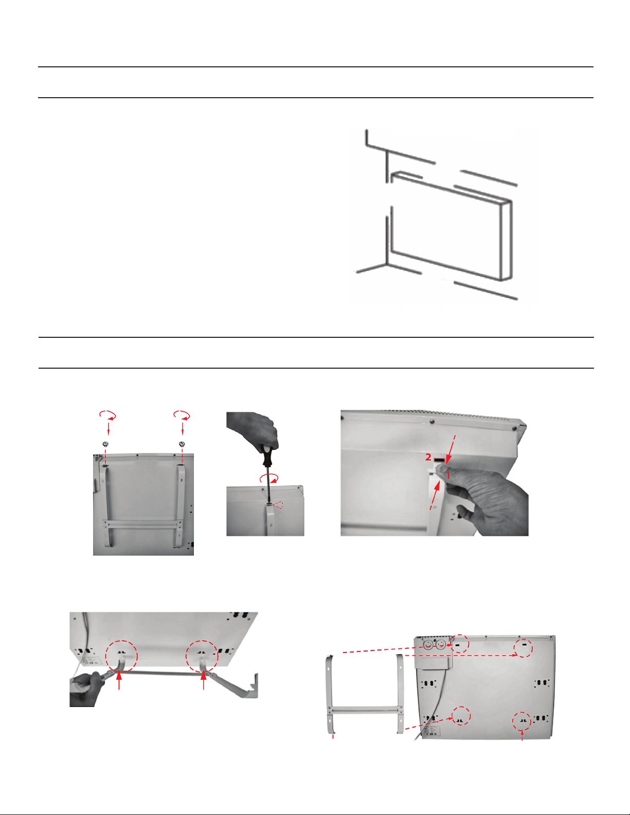
FIXED WALL MOUNT OPTION–INSTALLATION
1. The wall brackets supplied with the heater must be
used for the wall mount option
2. The heater should be positioned observing the
minimum clearances stated around the heater:
MINIMUM CLEARANCES (SEE FIG 1) :
From top surface of heater 18” (450mm)
From side of heater 10” (250mm)
From bottom of heater 6” (150mm)
Do not locate the heater where a draft may affect
the ambient temperature readings, and thus the
controll setting.
3. First remove the wall bracket from the rear housing
of the heater. Unscrew the (2) screws located on
the top of the two vertical bars of the wall bracket
(see Step1 on page 3).
4. Pull out the top of the bar by pressing rmly on both
upper tabs slotted into the rear housing (Step 2).
PORTABLE FLOOR MOUNT OPTION–INSTALL SUPPORT FEET
5. Slide the wall bracket down to remove it from the
rear housing (Step 3).
6. Fix the wall bracket securely to the wall through
the (4) screw holes provided. Use wall anchors if
necessary (not provided).
7. Hold the heater in the upright (vertical) position.
and position the top of heater against the wall
bracket. Push the bottom slots on the heater’s
back enclosure onto bottom tabs on the vertical
bracket bars. Pull up on the heater to seat the
heater onto the bracket.
8. Push the heater toward the top of the bracket’s
vertical bars, rmly seating the bracket tabs into
the top slots on the back of the heater enclosure.
Tighten the (2) screws on the top of the bracket’s
vertical bars to lock the heater to the mounting
bracket (Step 4).
1. Turn the heater upside down begin assembly of the
two support feet by unscrewing the wing-nuts.
2. Position the support feet with the longer section at
the rear of the heater as shown (Fig.1-2)..
3. Reinstall the wing nuts and be sure both wing-nuts
are tightened rmly and the casters on the feet are
secure.
4. Turn the heater upright before operating it.
REAR
ELECTRICAL CONNECTION
• The heater must be powered with 120V 60Hz
single phase current.
• The power outlet must be properly polarized and
grounded. Use of a ground fault circuit interrupter
(GFCI) is always recommended
• The proper electrical outlet, circuit breaker, etc.,
must be installed by a qualied electrician.
• Use of an extension cord is not recommended.
4
Page 5

Heat Controller Glass Panel Heater Owner’s Manual
OPERATION
POWER
SWITCH
CONTROL
PANEL
LED
DISPLAY
• MODE BUTTON: There are four modes: LO, HI,
AUTO, and STANDBY. Press the MODE button
to scroll through the functions in the following
sequence:
• LO → HI → AUTO → STANDBY
The power switch and control panel are located on
the right side of the heater enclosure.
The LED display shows in the upper right corner of
the glass panel on the front of the heater.
STANDBY: The unit does not generate any heat
when in STANDBY mode. All settings are saved
while in STANDBY mode.
To exit the STANDBY mode, press the Mode button
until the desired mode is displayed.
LO: low-power heating.
HI: high-power heating.
AUTO: In the automatic mode, the desired
temperature can be set using the TEMP button.
When the ambient temperature reaches (or
exceeds) the set temperature, the heater will stop
heating. When the ambient temperature is below
the set temperature, the heater automatically
will switch to HI power to bring the ambient
temperature up to the set temperature.
• TEMP BUTTON: The temperature setting range is
41°F to 95°F (5°C to 35°C).To set the temperature,
press the TEMP button and the LED display will
show either the default temperature setting value of
75°F (24°C) or the last set temperature.
Press the TEMP button again to set the desired
temperature value. Once the desired temperature
is set, the display will show the set temperature for
5 seconds, then will display the current ambient
temperature.
5
Page 6

Owner’s Manual Glass Panel Heater Heat Controller
TIMER FUNCTION
The user can set a specic time in the standby mode
using the TIMER OFF and TIMER ON buttons.
• TIMER OFF button: When the heater is working,
press the TIMER OFF button to set the time off.
The time range is 1hr to 24hr, in 1 hour increments.
When TIMER OFF is pressed, the LED display
shows either the default timing (0hr, 0hr meaning
no timer setting) or the last regular timer setting.
Continue to press the TIMER OFF button to set the
timing. When set, the display will show the TIMER
OFF setting for 5 seconds, and then display the
ambient temperature.
When the timer setting expires, the heater will
automatically stop heating—if the timer is set
for 3hr, for instance, the heater will turn off after
operating for three hours.
TIMER ON button: In standby mode, the TIMER
ON button is used to set a time delay for the unit
to start heating. The time range is 1hr to 24hr, in
1 hour increments. Press and hold the TIMER
ON button and the LED display shows either the
default timing (0hr, 0hr meaning no timer setting) or
the last TIMER ON setting. Continue to press the
TIMER ON button to set the timing. The heater will
automatically start to heat in the AUTO mode when
the set time on is reached.
• Temperature unit selection: Pressing the TEMP
and the MODE buttons at the same time shifts the
temperature unit between Fahrenheit and Celsius.
If the power is turned off either by using the ON/
OFF switch or disconnecting the power source, the
display will automatically revert to Celsius scale.
Putting the unit in STANDBY mode will not change
the setting.
• Alarm indicator: When the thermostat is
disconnected, the red indicator will light up, nothing
will display on the screen, and the heater will
stop working. When the machine cools down, the
thermostat and the heater will restart.
• Remote control: The remote
control operates in the same
manner as the control panel on
the heater. For safety reasons, the
remote control does not offer the
TIMER ON feature.
OPERATION SAFETY FEATURES
1. If the heater overheats for any reason, a thermal
cut-out switch discontinues power to the heater,
preventing excessively high heat hazards.
MAINTENANCE & SERVICE
1. Before you clean the appliance, switch the heater
to OFF and wait until it has cooled down.
2. Use a soft cloth to wipe off the panel heater
housing.
3. Clean the upper and lower grilles of the unit
periodically.
4. Do not use water, detergents, abrasive cleaning
liquids or chemical agents (alcohol, gasoline, etc.)
to clean the heater.
2. The heater also is equipped with a tip-over switch
which turns OFF power to the heater in the event
that the heater falls over or is knocked over.
5. Periodically check that there is no dust blocking the
vent slots on the top or bottom of the heater. Clean
the vent slots as necessary.
Note on Initial Start Up : There may be a trace of
smoke or slight odor when unit is rst operated. Do
not be alarmed as this will quickly dissipate.
For service, contact an authorized servicer or
qualied electrician. There are no parts of the
heater that are user serviceable.
6
Page 7

Limited Express Warranty
Comfort-Aire® Convection Heater
LIMITED ONE (1) YEAR PARTS EXPRESS WARRANTY
Heat Controller warrants all parts of the Infrared Heater
to be free from defects in workmanship and materials for
normal residential use and maintenance for one (1) year
from the date of purchase by the original consumer. This
Express Limited Warranty applies only when the Infrared
Heater is installed and operated per Heat Controller
installation and operating instructions for normal use.
EXCEPTIONS
The Limited Express Warranty does not cover normal
maintenance—Heat Controller recommends that regular
inspection/maintenance be performed according to the
Installation and Operation Manual. Additionally, labor
charges, diagnostic charges, transportation charges for
replacement parts, or any other service calls/repairs are
not covered by this Limited Warranty. It also does not cover
any portion or component of the system that is not supplied
by Heat Controller, regardless of the cause of failure of
such portion or component.
CONDITIONS FOR WARRANTY COVERAGE
• Unit must be operated according to Heat Controller
operating instructions included with the unit and cannot
have been subjected to accident, alteration, improper
repair, neglect or misuse, or an act of God (such as a
ood)
• Installation must be according to Heat Controller
installation instructions
• Rating plate has not been altered or removed
• Unit is not operated in a corrosive environment
• Performance cannot be impaired by use of any product
not authorized by Heat Controller, or by any adjustments
or adaptations to components
• Damage has not been a result of inadequate wiring or
voltage conditions, use during brown-out conditions, or
circuit interruptions
DURATION OF WARRANTY & REGISTRATION
The warranty begins on the date of purchase by the
orginal consumer. The consumer must register at www.
heatcontroller.com within 90 days of purchase. The
consumer must retain a receipted bill of sale as proof of
warranty period. Without this proof, the express warranty
begins on the date of shipment from the factory.
REMEDY PROVIDED BY THE LIMITED EXPRESS
WARRANTY
The sole remedy under the Limited Warranty is replacement
of the unit. If for any reason the replacement product is no
longer available during the warranty period, Heat Controller
shall have the right to allow a credit in the amount of the
current suggested retail price of the product instead of
providing replacement.
LIMITATION OF LIABILITY
1. There are no other express or implied warranties. Heat
Controller makes no warranty of merchantability. We
do not warrant that the unit is suitable for any particular
purpose or can be used in buildings or rooms of any
particular size or condition except as specifically
provided in this Installation and Operation document.
There are no other warranties, express or implied, which
extend beyond the description in this document.
2. All warranties implied by law are limited in duration to
the one-year term of the Parts Warranty. Your exclusive
remedy is limited to the replacement of defective parts.
We will not be liable for any consequential or incidental
damages caused by any defect in this unit.
3. This warranty gives you specic legal rights and you
may also have other rights which vary from state to
state. Some states do not allow limitation on how long
an implied warranty lasts or do not allow the exclusion
or limitation of incidental or consequential damages, so
the above limitations or exclusions may not apply to you.
4. No warranties are made for units sold outside the
continental United States and Canada. Your distributor
or nal seller may provide a warranty on units sold
outside these areas.
5. Heat Controller will not be liable for damages if our
performance regarding warranty resolution is delayed by
events beyond our control including accident, alteration,
abuse, war, government restrictions, strikes, re, ood,
or other acts of God.
HOW TO OBTAIN WARRANTY SERVICE OR PARTS
If you have a warranty claim, contact Heat Controller
at 517-787-2100. Have the model number and date of
purchase available for this call. Do not return your unit to
the store where it was purchased.
Owner responsibilities are set forth in the instruction manual—read it carefully.
7
Page 8

Design, material, performance specications and components
subject to change without notice.
:HOOZRUWK$YH-DFNVRQ0,3KZZZKHDWFRQWUROOHUFRP
07/2013
 Loading...