

Page 1
INSTALLATION, OPERATION
& MAINTENANCE MANUAL
Multi-Position Air Handler
Hydronic Heat with PSC Motor
HWCGxxT0A
Heat Controller • 1900 Wellworth Ave. • Jackson, MI 49203 • (517)787-2100 • www.heatcontroller.com
Page 2
Multi-Position Air Handler with Hydronic Heat with PSC Motor HWCGxxT0A Heat Controller
REQUI RE D
Safety Instruction
Potential safety hazards are alerted using symbol.
The symbol is used in conjunction with terms that
indicate the intensity of the hazard.
WARNING
This symbol indicates a potentially
hazardous situation which if not avoided, could result in
serious injury, property damage, product damage or
death.
CAUTION
This symbol indicates a potentially
hazardous situation which if not avoided, may result in
moderate injury or property damage.
WARNING
individuals meeting the requirements specified by
NATE may use this information. Property and
product damage or personal injury hazard may
occur without such background.
WARNING
disconnected prior to servicing. Failure to do so may
cause personal injury or property damage.
WARNING
ured to permit installation in accordance with local and
national building codes. It is the installer’s responsibility
to ensure that product is installed in strict compliance
with national and local codes. Manufacturer takes no
responsibility for damage (personal, product or property)
caused due to installations violating regulations. In
absence of local/state codes, refer to National Electric
Code NFPA 90A & 90B Uniform Mechanical Code
(CEC or CSA for Canadian Installations).
WARNING
enclosed area, such as a garage or utility room with any
Carbon Monoxide producing devices (i.e. automobile,
space heater, water heater etc.) ensure that the
enclosed area is properly ventilated.
CAUTION
accessories should be used when installing or modifying
this unit unless it is so noted in these instructions. Some
localities may require a licensed installer/service
personnel.
WARNING
installations.
Certified technicians or those
All power sources should be
Product designed and manufact-
When this unit is installed in an
Only factory authorized kits and
Unit is not approved for outdoor
WARNING
The unit is designed for operation
with 108/120 V, single phase, 60 Hz power supply.
Manufacturer will not be reponsible for damages caused
due to modification of the unit to operate with alternative
power sources.
Inspection
On receiving the product, visually inspect it for any major
shipping related damages. Shipping damages are the
carrier’s responsibility. Inspect the product labels to
verify that the model number and options are in
accordance with your order. Manufacturer will not accept
damage claims for incorrectly shipped product.
Installation Preparation
Read all the instructions in this guideline carefully while
paying special attention to the WARNING and CAUTION
alerts. If any of the instructions are unclear; clarify with
certified technicians. Gather all the tools needed for
successful installation of the unit prior to beginning the
installation.
This unit is designed for zero clearance installation on
three sides and adequate clearance to provide access
for serivce in the front. A min of 2.5 – 3.5 feet clearance
is recommended on the front end.
If the unit is to be installed in garages, warehouses or
other areas where they may be subjected to physical
damage, adequate protective barriers must be installed.
Unit MUST be installed 18” away from source of ignition.
If the unit is located in high humidity areas like attics or
unconditioned garage; the air handler casing might
experience nuisance sweating. In such installation
scenarios, wrapping the casing with a 2” fiberglass
insulation with vapor barrier SHOULD be used.
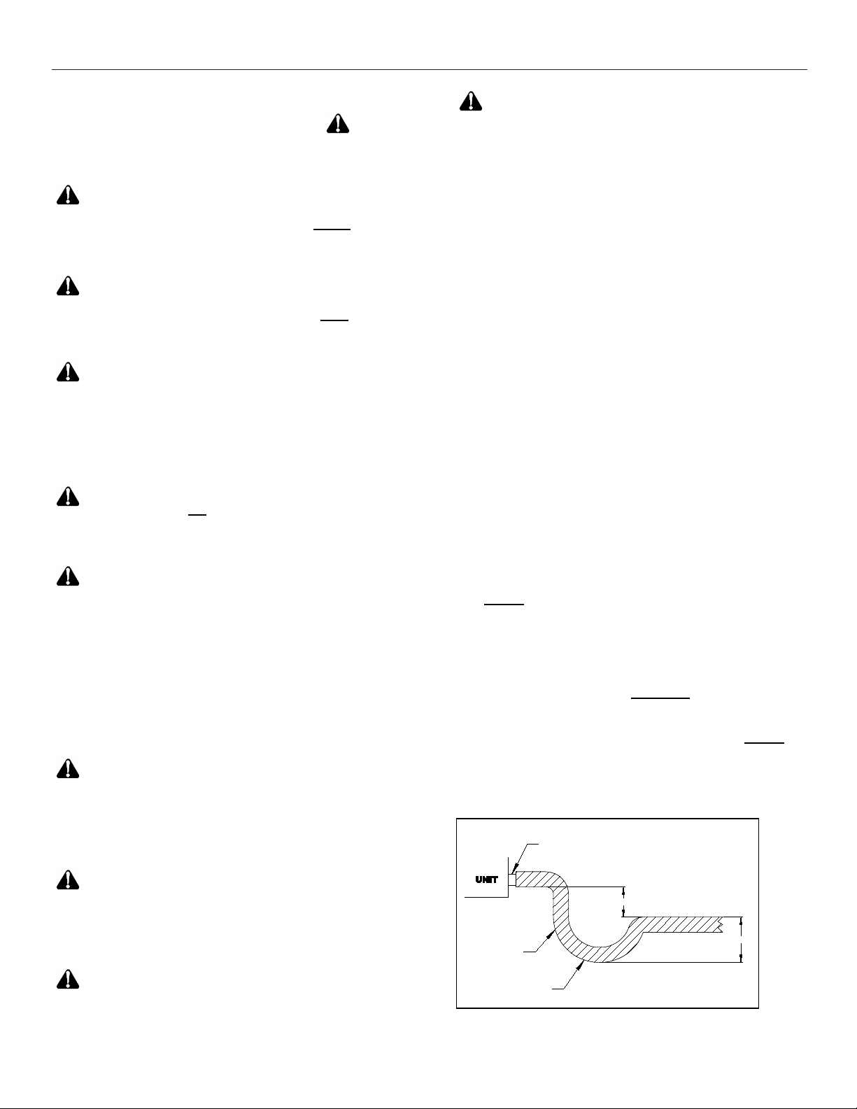
The drain lines must be installed with ¼” per foot pitch to
provide free drainage. A condensate trap MUST be
installed on the primary drain line to ensure proper
drainage of the condensate. The trap must be installed
in the drain line below the bottom of the drain pan.
Figure 1 illustrates the typical drain trap installation
DRAI N
CONNECTI ON
2" MINI MUM
FLEXIBLE
TUBI NG- HOSE
OR PIPE
A POSITIVE
LIQUID SEAL IS
Figure.1. Typical drain line trap set up
3" MINI MU
2
Page 3
Heat Controller Multi-Position Air Handler with Hydronic Heat with PSC Motor HWCGxxT0A
Ductwork
Duct systems should be installed in accordance with
standards for air-conditioning systems, National Fire
Protection Association Pamphlet No. 90A or 90B. They
should be sized in accordance with National
Environmental System Contractors Association Manual
K, or whichever is applicable.
On any job, non-flammable flexible collars should be
used for the return air and discharge connections to
prevent transmission of vibration. Although these units
have been specially designed for quiet vibration-free
operation, air ducts can act as soundboards can, if
poorly installed, amplify the slightest vibration to the
annoyance level.
All main supply and return air drops should be properly
size as determined by the designer of the duct system
and should not necessarily be the size of the duct flange
openings of the unit.
When installing a central air return grille in or near the
living space, it is advisable to design the ductwork so
that the grille is not in direct line with the opening in the
unit. One or two elbows and acoustical duct liner will
also assure a quieter installation and system.
It is recommended that wherever supply and return air
sheet metal duct pass through unconditioned areas, they
be insulated to prevent excessive heat loss during
heating operation. When applied in conjunction with
summer air conditioning, sheet metal duct routed
through unconditioned areas should be insulated and
have an outside vapor barrier to prevent formation of
condensation.
Installation
CAUTION
sized. The tonnage of the outdoor unit should never
exceed the tonnage of this unit.
WARNING
dry nitrogen pre-charge. Release the pressure through
the Schrader valve test port prior to installation. If
holding pressure is not present, return coil to distributor
for exchange.
Clean coil fins with degreasing agent or mild detergent
and rinse fins clean prior to installation.
All connection joints should be burr-free and clean. Not
removing the burr and cleaning may increase chances of
a leak. It is recommended to use a pipe cutter to remove
the spun closed end of the suction line.
To avoid damage to grommets (where present), remove
these prior to brazing by sliding over the lines. Use a
quenching cloth or allow the lines to cool before
reinstalling the grommets.
Ensure that the unit is adequately
The coil was manufactured with
WARNING
Prior to connecting the water
(hydronic) coil, make sure that the hot water supply is
turned off. Water from the heater could be extremely hot
and might result in burns and other personal injury along
with equipment damage. Ensure that proper saftey gear
is being used prior to making connections.
CAUTION
Only lead free solder should be
used to connect water (hydronic) coil to the hot water
source.
CAUTION
Some coils may include a
Schrader valve on the suction manifold. Ensure that the
Schrader valve and valve core (where present) are
protected from heat to prevent leakage.
Metering Device
Coils use a TXV of metering device. Instructions below
are for the metering device. Ensure that the instructions
are thoroughly read and understood.
TXV Coils:
WARNING
MUST be protected from overheating during brazing.
The sensing bulb and TXV body must be covered using
a quench cloth or wet cloth when brazing. Pointing the
brazing flame away from the valve and sensing bulb
provide partial protection only.
CAUTION
compatible with the refrigerant used in the outdoor
system (R22 or R410A). TXV caps are painted green for
R22 or pink for R410A. In absence of color, the caps will
be marked with the compatible refrigerant.
CAUTION
according to the capacity of the outdoor unit. Failure to
install the right valve can lead to poor performance and
possible compressor damage.
TXV Bulb Mounting
The orientation and location of the TXV bulb has a major
influence on the system performance.
CAUTION
direct contact with the suction/vapor line. Gap between
the bulb and tube should be avoided. Failure to eliminate
gaps will impair the proper functioning of the TXV valve.
It is recommended that the TXV bulb be installed parallel
to the ground (in a horizontal plane). The bulb position
should be above and between 4 o’clock and 8 o’clock.
3
The sensing bulb and TXV body
Ensure that the TXV selected is
The valves should be sized
Ensure that the TXV bulb is in
Page 4
Multi-Position Air Handler with Hydronic Heat with PSC Motor HWCGxxT0A Heat Controller
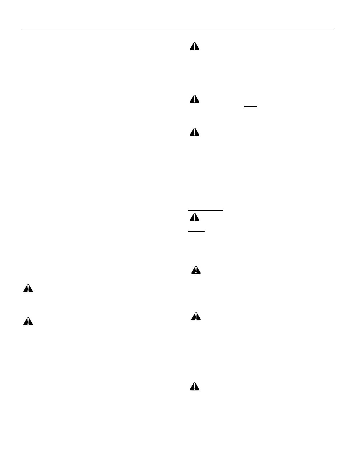
Fig. 2 shows the recommended position for the TXV bulb
installation in the horizontal plane.
The TXV sensing bulb SHOULD be mounted using the
metal clamp provided. In order to obtain a good
temperature reading and correct superheat control, the
TXV sensing bulb must conform to ALL of the following
criteria:
1) The sensing bulb must be in direct and
continous contact with the suction line
2) The sensing bulb should be mounted
horizontally on the suction line.
3) The sensing bulb must be mounted above and
between the 4 and 8 o’clock position on the
circumference of the suction line.
4) The sensing bulb must be insulated from outside
air.
SUCTION/VAPOR LINE
METAL STRAP
TXV BULB POSI TION
4 O'CLOCK OR
8 O'CLOCK
Fig.2. Recommended location of the TXV bulb in a
horizontal orientation
The mounting location and insulation guards the sensing
bulb from false reading due to hot outside air or liquid
refrigerant formed inside the suction/vapor line.
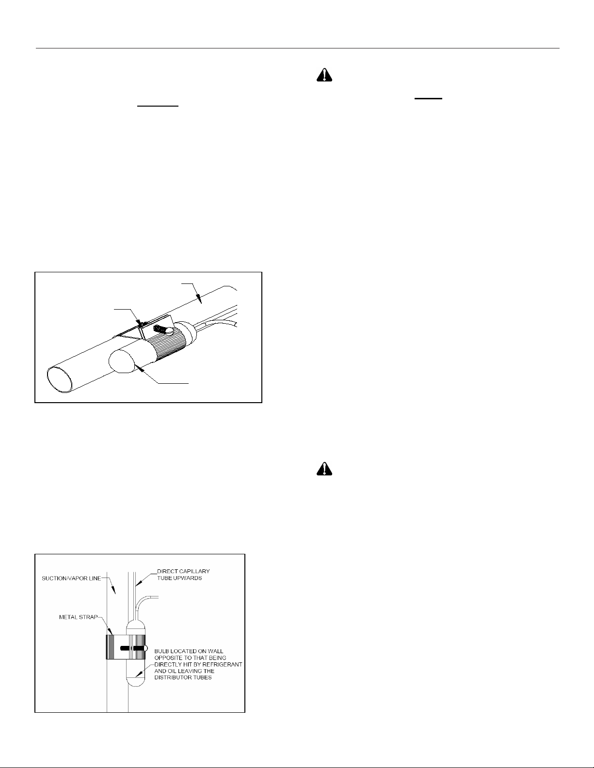
As recommended earlier, the TXV sensing bulb should
be mounted in a horizontal plane in relation to the
suction/vapor line. However, in case such a mounting is
not feasible and the sensing bulb has to be mounted
vertically; then place the bulb as shown in Fig.3.
Fig.3. Sensing bulb mounted in a vertical orientation
4
CAUTION
If the TXV sensing bulb is mounted
vertically; the capillary MUST be directed upwards. The
bulb must be mounted on the wall opposite to that being
directly hit by the refrigerant and oil leaving the
distributor tubes.
Field – Installed Expansion Valve Coils
Remove the valve identification sticker from the valve
and place it adjacent to the model number on unit name
plate.
When installing an expansion valve, it is not necessary
to remove all the access panels and slide the coil out of
the housing.
1) Disassemble the flowrator body using two
wrenches. Unscrew the body with a counterclockwise motion.
2) Replace the white Teflon seal in place (located
between the halves).
3) Remove the existing flowrator piston using a
small wire or pick.
4) Inspect the TXV box to confirm that the valve is
compatible with the refrigerant in the system.
5) Remove the valve from the box and note the
location of the inlet side (threaded male port)
and the outlet side (female swivel nut port).
6) After ensuring that the white Teflon seal is still in
place inside the flowrator body, screw the
female swivel nut onto the flowrator body.
7) Place the attachment nut on the liquid line.
8) Braze the stub-out portion to the liquid line and
let cool.
WARNING
joint while hot. Touching it may cause sever burns.
9) Remove the additional white Teflon seal ring
from the box and place on the shoulder just
inside the inlet port. Screw the nut attached to
the stub-out portion of the flowrator body onto
the inlet port of the TXV.
10) Tighten all connections taking care to use proper
Some coils come with a Schrader valve on the suction
line. If a Schrader port is present
Coils without Schrader Ports
back up.
11) Remove valve stem from the Schrader port
mounted on the suction line
12) Screw flare nut on TXV equalization tube in to
the Schrader valve stem
11) Locate a convenient spot on the suction line
and punch a ¼” hole with a pick or other suitable
tool.
Do not attempt to touch the braze
Page 5
Heat Controller Multi-Position Air Handler with Hydronic Heat with PSC Motor HWCGxxT0A
CAUTION
enter suction manifold.
12) Insert TXV equalizer tube approximately 3/8”
into the hole and apply solder to seal.
Fig.4 shows the components of a typical TXV assembly
TXV BULB
Fig.4. Components of a typical TXV assembly
CAUTION
valve may require the use of a hard-start kit. Follow the
outdoor unit manufacturer’s guidelines.
Do NOT drill a hole as chips will
DISTRIBUTOR
TEFLON O- RINGS
TAIL PIECE
Using a non-bleed expansion
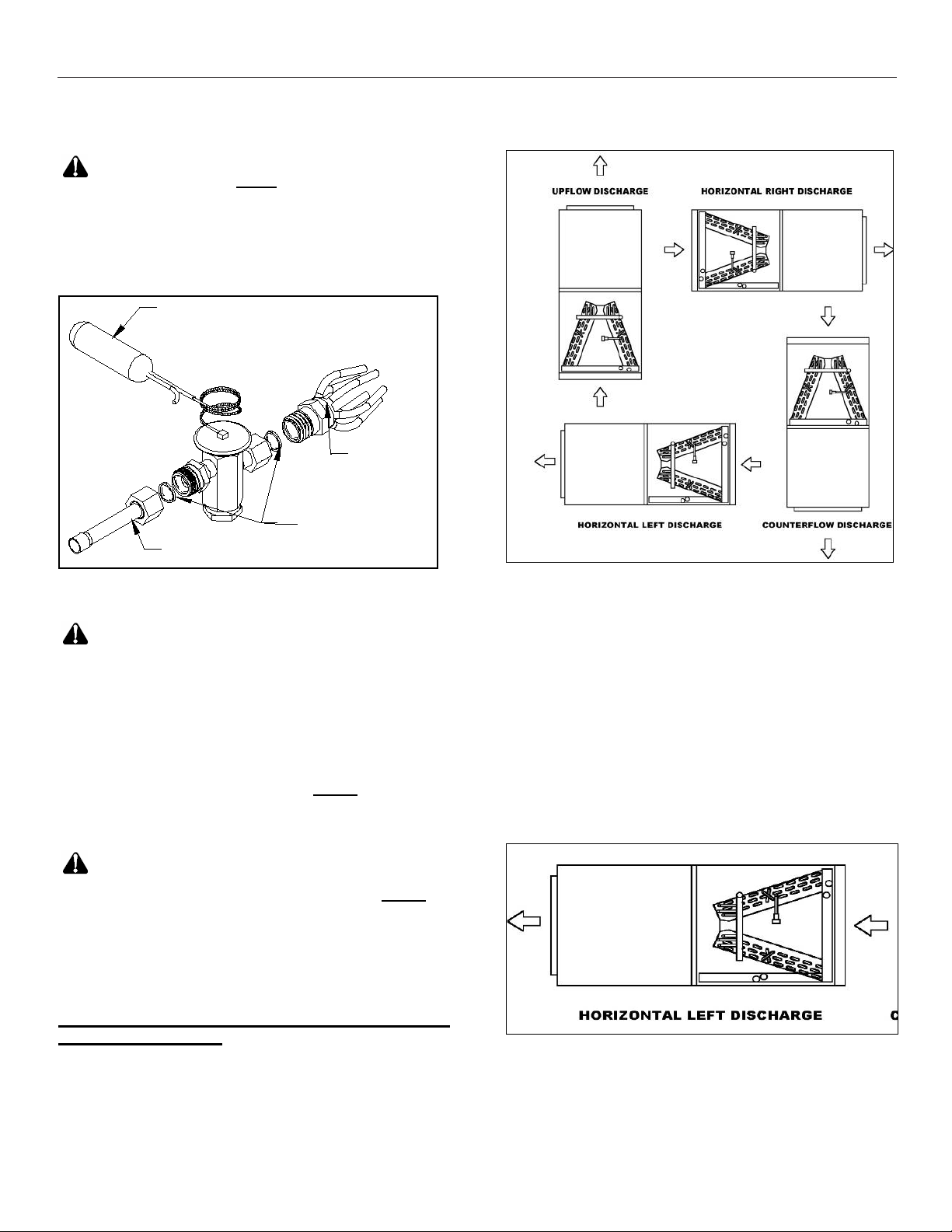
Air handler orientation
This unit can be installed in vertical or right horizontal
position without modifications. In case of a counterflow
application, the horizontal drain pan MUST be removed.
Fig. 5 shows the various orientations this air handler can
be installed in.
CAUTION
horizontal orientation; an auxiliary drain pan MUST be
provided by the installer and placed under the entire unit
with a separate drain line that is properly sloped and
terminated in an area visible to the home owner. The
auxiliary pans provide extra protection to the area under
the unit should the primary and secondary drain plug up
and overflow. As expressed in our product warranty;
failure to follow this installation requirment will void
the product warranty. The drains from the auxiliary
drain pan must be installed according to the local
building codes.
When the unit is used in an
Fig.5. Various airflow orientation
Horizontal Left-hand Installation
• With Air Handler in vertical position remove all
access panels.
• Remove horizontal drain pan from right hand
side. Disconnect any drain connections.
• Relocate the removed horizontal drain pan on to
the left side and reconnect the drain
connections.
• “P” traps must be installed on primary and
secondary drains of the horizontal drain pan.
• Reinstall all access panels to the unit.
Fig.6. Air flow direction in Horizontal Left application
5
Page 6

Multi-Position Air Handler with Hydronic Heat with PSC Motor HWCGxxT0A Heat Controller
Counter Flow Installation
Fig.7. Air Handler parts and changes for Counter flow
• Before positioning the Air Handler in the counter
flow position, remove lower access panels, filter
panel and filter.
• Remove the A-Coil assembly with the horizontal
drain pan; discard the horizontal drain pan (not
required for counter flow application).
• Rotate the Air Handler 180° to the counter flow
position.
• Remove the coil deck and filter channel, rotate
the filter channels 180° and re-attach in the
same location they were removed from.
• Rotate the coil deck 180° and re-attach in the
holes near the center of the cabinet (screws not
provided).
• Slide the A-coil assembly into the cabinet on the
coil deck (without the horizontal drain pan).
Note: Push the coil pan assembly all the way to
the rear of the cabinet until it locks under the
bracket in the rear.
• Place the 3” x 16” counter flow plates at the
outside bottom of the coil as shown in FIG. 8.
• Replace the access panels and filter panel.
Electrical Installation
These units are designed for single or three phase 120
volts, 60 Hz power supply. Wire selection and wiring
must be in accordance with the National Electric Code
(or CEC for Canadian installations) and/or local codes.
Unit terminals are designed to accommodate copper and
aluminum wirings. If aluminum wiring is used; please
observe special precautions relative to sizing, wire
connections and corrosion protection.
Fig.9 shows the typical electrical connections required
for A/C only and heat pump applications.
The unit ships with a micro-processor based board
which controls the electrical functioning of the unit. An
inspection of the controls is recommended prior to startup.
Fig.10 provides a schematic of the control board present
in the unit. The units ship from the factory with the
aquastat jumper in the OFF position (right two pins) and
the heating selector in the HW position (right two pins). If
an aquastat is used in the application; the jumper should
be changed to ON position (left two pins).
Note: Terminals T and N located on the top right side
of the board are not intended for field use and should be
left unconnected.
CAUTION
in the OFF position at all times; except for when an
aquastat is used in the application. If the jumper is
moved to the ON position without installing an aquastat
the blower will not be energized.
When an aquastat is present, the blower will be
energized at the aquastat temperature settings.
The aquastat (AQ) jumper must be
Fig 9. Electric connections
3" X 16" Metal Plate
Fig.8. Position of plates required in counter flow
6
CAUTION
This model is shipped without factory a installed pump,
therefore the two black wires should be connected to the
boiler terminals T T. In applications where a boiler is
used to provide the hot water supply, these wires shouId
Page 7

Heat Controller Multi-Position Air Handler with Hydronic Heat with PSC Motor HWCGxxT0A
be connected to the boiler. Terminals T T are normally
open dry contacts.
In applications where a valve is used to regulate hot
water supply, the two black wires located on the T T
terminals should be removed and placed on the two
terminals reading “VALVE”. The open ends of the wires
should be connected to the valve according to local
requirments and instructions of the valve manufacturer.
On call for heat, 24V will be sent to the field installed
valve or pump relay.
when the sensor sees 40ºF. The pump stays ON for a
minimum of 30 sec.
The board has an built-in timer which circulates hot
water 6 times a day for 60 sec each time to prevent the
coil from freezing.
Start up
WARNING
all water lines MUST be purged of air prior to starting the
pump. Failure to do so could result in pump damage.
Manufacturer will not be responsible for any property or
physical injury caused by failure to follow this instruction.
WARNING
should be in the range of 120º - 180º F. Water at these
temperatures can cause first-degree burns. Use of
proper saftey gear while installing or servicing the
equipment is strongly recommended, as is installation of
a water-tempering valve (for water temperatures of
above 140ºF) to supply lower temperature water to
fixtures in the house. N170L series or equivalent should
be used.
Connect the hydronic coil to the water heater system as
shown in Fig 11. Use flexible piping and insulate all
pipes. Plumbing must be in compliance with state or
local codes (Code CMR248 in Massachusetts). The
units for hydronic heat have different top and heater box
configurations. This configuration is not suitable for
electric heat. DO NOT try to install a hydronic heater in a
unit not equipped for it. Verify connections: hot water to
“in” and cold water to “out”. 7/8” ODstubs are provided
for plumbing connections. Bleed the air flow system
through the bleeder port or optional valve.
The hot water (hydronic) coil and
Hot water flowing to the coil
Purging The System
1) Open air vent and allow water heater to fill with
water. Close air vent when water heater is full and
all air has been purged.
2) Ignite water heater. Set thermostat on water heater
to 140 degrees.
3) Close the valve on the hot water supply from the
water heater ("A") and open the valve on the coldwater return to the water heater ("B"). Then open the
air vent in the fan coil. Use a bucket or hose to
discard water during purging process at air bleed
Fig.10. Micro-processor control board
On call for heat water will circulate through the water
(hydronic) coilfor 60 secs prior to energizing the blower.
After the thermostat is satisfied, the blower will continue
to stay energized for a minimum of 30 sec. This helps
maximize heating efficiency.
The freeze protection sensor is connected to the FP and
R terminals. These are normally open and will close
7
valve. Purge air completely from line.
4) Once air is purged, close return valve ("B") and open
supply valve ("A"). Purge the coil and lines of air
completely.
5) After air is purged from the system and filled with
water, open the return valve ("B") and the supply
valve ("A"). Then close the air vent in the fan coil.
6) Apply power to the fan coil and set the room
thermostat on heat. Raise the temperature setting to
activate the circulating pump
7) Check the pump to ensure proper operation. The
water inlet of the unit should be hot if the water
Page 8

Multi-Position Air Handler with Hydronic Heat with PSC Motor HWCGxxT0A Heat Controller
CFM V. EXTERNAL STATIC
PRESSURE
HWCG24T0A
HWCG36T0A
HWCG48/60T0A
temperature in the water heater has reached the set
point. If water is not being circulated through the coil
but the pump is running, then open the air bleed
valve in the unit and purge any air left in the system.
8) Adjust the water heater thermostat so that the water
temperature entering the hot water coils is 120 –
180ºF depending on the amount of heat required by
the structure. This is done with the unit energized
and operating long enough for all temperatures to
stabalize.
Note: Massachusetts applicable diagram at end of manual
Fig.11. Schematic of hydronic unit set up and typical ‘T”
installation.
After all connections are made, start-up and check-up of
the unit must be performed before proper evaluation of
the entire system can be made. Make sure that heat
anticipator is properly set as noted on thermostat
instructions.
Load requirements can vary in each residence and it
may be necessary for the installer or homeowner to
make slight adjustments to the heat anticipator setting
for longer or shorter cycles. It is recommended to
change the setting no more than plus or minus 0.05
amps at a time. Greater changes can cause the unit to
rapid cycle or remain on excessively. To properly check
the unit's operation, the installer should have an
electrical current measuring device (0-10 amp Amprobe,
Fluke), air pressure measuring device (0-1.0 in slope
gauge), and a temperature-measuring device (0-200ºF
thermometer).
Install the Amprobe to measure blower current, the slope
gauge to measure static air pressure at the units and the
temperature device to measure unit supply and return air
temperature. Before taking measurements, be sure that
all registers, grilles and dampers are open or set to their
proper positions. Be sure that clean filters are in place.
Temperature measuring device must be installed to
obtain average temperature at both inlet and outlet. For
outlet, measure temperature of each main trunk at a
location far enough away to avoid heater radiation and
read the average temperatures. Table 1 below shows
the CFM that should be achieved at various external
static pressures
SPEED
MODEL
ABM18/19,24/25
ABM30/31,36/37
ABM42/43,48/49,60/61
Table 1. CFM delivered at various external statics
MOTOR
TAP
LOW 780 740 700 650 580
HIGH 850 800 740 690 620
LOW 1000 980 920 870 800
HIGH 1210 1190 1160 1130 1070
HIGH 1360 1340 1310 1280 1230
MED 1530 1470 1420 1360 1310
LOW 1730 1670 1600 1540 1480
AMP
0.10 0.20 0.30 0.40 0.50
2.8
5.4
9.5
Electric Heat Controls
• Turn on power supply. Set thermostat fan switch to
on. Set the cooling indicator to maximum, heating to
minimum. System switch may be on heat or cool.
Check slope gauge measurement against
appropriate air flow chart. Make damper, register
and motor speed adjustments to obtain required
airflow.
• Set thermostat fan switch to auto, system to heat
and thermostat heating indicator to maximum heat.
Blower should start and all heat be energized.
• Check air flow using temperature rise method.
8
Page 9

Heat Controller Multi-Position Air Handler with Hydronic Heat with PSC Motor HWCGxxT0A
( )
BTUHOUTPUT
CFM×=
08.1
NOTE: BTUH output should be computed by VOLT x
AMPS x 3.4 = BTUH OUTPUT. Since line volt can vary,
do not use nameplate rating to determine output.
RISETEMP
Operation and Maintainance
Below are brief descriptions of the key components of
the unit and installation. This manual only provides a
general idea of the components and recommended
practices. The installer should use best judgement to
ensure safe installation and operation of the unit.
1) Room Thermostat- This is the device that controls
that operation of your heating and/or cooling unit. It
senses the indoor temperature and signals the
equipment to start or stop maintaining the
temperature you have selected for your comfort. The
room thermostat should be in a central, draft free
inside wall location for best operation. Do not place
any heat producing apparatus such as lights, radio,
etc., near the thermostat as this will cause erratic
operation of the comfort system. The thermostat can
accumulate dust or lint which can affect its accuracy.
It should be cleaned annually.
2) Air Filter(s) - All central air moving comfort systems
must include air filter(s). These filters will be located
either in the equipment or in the return air duct
system upstream of the equipment. The filter(s)
removes dust and debris from the air thus helping to
keep your air-conditioned space clean. More
important, the filter keeps dust and debris from
collecting on the heat transfer surfaces thus
maintaining optimum equipment efficiency and
performance. Inspect and clean or replace filters
every month. This routine maintenance procedure
will pay big dividends in reduced operating cost and
reduced service expense. Never operate comfort
equipment without filter(s).
3) Fuses and/or Circuit Breakers- This comfort
equipment should be connected to the building
electric service in accordance with local and
National Electric codes. This electrical connection
will include over-current protection in the form of
circuit breakers. Have your contractor identify the
circuits and the location of over current protection so
that you will be in a position to make inspections or
replacements in the event the equipment fails to
operate.
4)
WARNING
a) Do not store combustible materials or use
gasoline or other flammable liquids or vapors in
the vicinity of this appliance.
9
b) Do not operate the comfort equipment with
panels removed.
c) Have your contractor point out and identify the
various cut-off devices, switches, etc., that serve
your comfort equipment. There is a main switch
that will cut off energy to your heating system.
Know where they are so that you may cut off the
flow of energy in the event of overheating.
5) Periodic Checkup and Service- This product is
designed to provide many years of dependable,
trouble-free comfort when properly maintained.
Proper maintenance will consist of annual check-ups
and cleaning of the internal electrical and heat
transfer components by a qualified service
technician. Failure to provide periodic checkup and
cleaning can result in excessive operating cost
and/or equipment malfunction.
6) Lubrication- Direct drive blower motors are equipped
with permanently lubricated bearings and do not
require further lubrication.
7) Air filter replacement: An air filter can restrict the
airflow of air to the fan coil if it is not cleaned or
replaced periodically. When replacing the air filter,
always replace with the same type and size as
originally furnished with the unit.
Hydronic Related General Information
1) Equipment Sizing
Select an air handler with a heating output that exceeds
the space heating loss of the structure and that has a
cooling coil sized to match the outdoor condensing unit.
Note: The heating output of the air handler or hot water
coil will not be greater than the output of the selected hot
water heater. Therefore, if the water heater is undersized
the heating BTUH of the air handler will be LESS than its
rated output.
2) Water Heater Selection
The following sizing information should only be used as
a basic guide to adequate water heater sizing because
of variations in each family's domestic hot water
requirements. For additional assistance in water heater
sizing contact a professional engineer.
Proper water heater sizing should consider both the
gallon capacity AND the BTU input of the water heater.
a. To determine water heater GALLON CAPACITY: A
minimum 40-gallon high recovery and/or high efficiency
gas or oil-fired water heater is recommended. The
following volume-sizing guide (Table 2.) is satisfactory in
most areas of the country:
Page 10

Multi-Position Air Handler with Hydronic Heat with PSC Motor HWCGxxT0A Heat Controller
600-800
40 gal
1000-1200
50 gal
2x40 gallons piped together
High input 50 gallons (63-75k Btu)
72-75gallons
2000
105k Btu
Table 2. Volume Sizing Guide
CFM Min Water Heater
1400-1600
b. To determine water heater BTU INPUT (assumes a
water heater recovery efficiency of 76%): For mild
climates: BTU INPUT=structure’s heat loss x 1.51. For
colder climates: BTU INPUT=structure's heat loss x
1.58.
3) Pump Replacement
a. Disconnect electrical power to the unit before
servicing.
b. Remove access door to reveal pump. Close supply
valve ("A") and return valve ("B"). Open the air bleed
valve to de-pressurize the system and drain water.
c. Remove the metal pump housing by loosening the
four screws on the pump. DO NOT UN-SOLDER PUMP.
d. Replace the new pump housing assembly and
reconnect components to the pump. Before assembling,
make sure that the runner on the o-ring is in place on the
pump housing.
e. Purge the system of the air as described earlier and
re-connect the electrical power.
Common Problems and Solutions
1) Noisy Pump
System may not be totally purged of air. Purge the
system again as described in the start up section above.
2) T&P valve on water heater weeps
This nomally occurs when a backflow preventer has been
installed in the cold water supply line to the water heater. An
expansion tank may be necessary to correct this problem.
Please contact a qualified plumbing professional for assitance.
3) Hot water is circulating through the water coil during
cooling cycle
The check valve may be stuck open and allowing hot water to
circulate through the coil.
4) Little or no heat from water coil
a. Purg the system
b. The inlet connections may be reversed at the fan coil
c. Water heater thermostat is not set at proper temp
d. Water heater thermostat is not caliberated
e. Dip tube in the water heater maynot be installed
correctly or could be restricted.
f. Look for restrictions in heating system from water
heater to fan coil. Some water heaters are supplied with
check valves. Remove any extra check valves except for
the one supplied with the fan coil
g. The air handler is undersized for space being heated
h. Water heater is undersized
Note: All units installed in Massachusetts are required to
be in compliance with CMR 248 Massachusetts State
Plumbing Code and/or Massachusetts Fuel Gas Code.
These codes require the use of an optional pump timer
to circulate the hydronic loop independent of the
thermostat.
10
Page 11

Heat Controller Multi-Position Air Handler with Hydronic Heat with PSC Motor HWCGxxT0A
hazard
Wiring diagram
disconnect all power before servicing. Failure to comply may result in property damage/ safety
HIGH VOLTAGE
11
Page 12

Multi-Position Air Handler with Hydronic Heat with PSC Motor HWCGxxT0A Heat Controller
Massachusetts applicable installation diagram
12
Page 13

Heat Controller Multi-Position Air Handler with Hydronic Heat with PSC Motor HWCGxxT0A
This page intentionally left blank.
13
Page 14

Multi-Position Air Handler with Hydronic Heat with PSC Motor HWCGxxT0A Heat Controller
This page intentionally left blank.
14
Page 15

Heat Controller Multi-Position Air Handler with Hydronic Heat with PSC Motor HWCGxxT0A
This page intentionally left blank.
15
Page 16

'XHWRRQJRLQJSURGXFWLPSURYHPHQWVVSHFLILFDWLRQVDQGGLPHQVLRQVDUH
VXEMHFWWRFKDQJHDQGFRUUHFWLRQZLWKRXWQRWLFHRULQFXUULQJREOLJDWLRQV'HWHUPLQLQJWKH
DSSOLFDWLRQDQGVXLWDELOLW\IRUXVHRIDQ\SURGXFWLVWKHUHVSRQVLELOLW\RIWKHLQVWDOOHU
$GGLWLRQDOO\WKHLQVWDOOHULVUHVSRQVLEOHIRUYHULI\LQJGLPHQVLRQDOGDWDRQWKHDFWXDOSURGXFW
SULRUWREHJLQQLQJDQ\LQVWDOODWLRQSUHSDUDWLRQV
,QFHQWLYHDQGUHEDWHSURJUDPVKDYHSUHFLVHUHTXLUHPHQWVDVWRSURGXFWSHUIRUPDQFH
DQGFHUWLILFDWLRQ$OOSURGXFWVPHHWDSSOLFDEOHUHJXODWLRQVLQHIIHFWRQGDWHRIPDQXIDFWXUH
KRZHYHUFHUWLILFDWLRQVDUHQRWQHFHVVDULO\JUDQWHGIRUWKHOLIHRIDSURGXFW
7KHUHIRUHLWLVWKHUHVSRQVLELOLW\RIWKHDSSOLFDQWWRGHWHUPLQHZKHWKHUDVSHFLILF
PRGHOTXDOLILHVIRUWKHVHLQFHQWLYHUHEDWHSURJUDPV
:HOOZRUWK$YH-DFNVRQ0,3KZZZKHDWFRQWUROOHUFRP
3/2014
 Loading...