

Page 1
INSTALLATION, OPERATION
& MAINTENANCE MANUAL
Residential Packaged
Geothermal Heat Pump
HP Series
1
/2 to 5 Tons
1
Heat Controller, Inc. • 1900 Wellworth Ave. • Jackson, MI 49203 • (517)787-2100 • www.heatcontroller.com
Page 2

Installation, Operation & Maintenance HP SerieS Heat Controller, Inc.
Table of Contents
Model Nomenclature ............................................................................................2
Safety Instructions ................................................................................................3
Pre-Installation......................................................................................................4
Physical Data........................................................................................................5
Vertical Unit Dimensions....................................................................................6-7
Vertical Installation.............................................................................................8-9
Water Connection Installation .............................................................................10
Ground-Loop Heat Pump Applications ..........................................................10-12
Ground-Water Heat Pump Applications ..............................................................13
Water Quality Standards ....................................................................................14
Hot Water Generator .....................................................................................15-17
Electrical Data ...............................................................................................18-22
Blower Performance Data ..................................................................................23
Wiring Diagrams ............................................................................................24-25
CXM Controls ................................................................................................26-28
Unit Start-Up and Operating Conditions ........................................................29-36
Preventive Maintenance .....................................................................................37
Troubleshooting .............................................................................................38-42
1
Page 3
Heat Controller, Inc. HP SerieS Installation, Operation & Maintenance
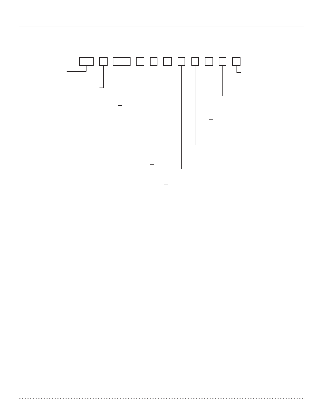
DRAWINGNO:
Decoder HP
S = STRAIGHT DISCHARGE, HORIZONTAL ONLY
Unit Nomenclature
HEAT CONTROLLER SERIES
TRH/TRV HPH/HPV
MODEL TYPE
HP = HEAT CONTROLLER RESIDENTIAL 410A
1 2 3 4 5 6 7
H P H A0 3 6 C1 5 0 A L B
CONFIGURATION
V=VERTICAL
H = HORIZONTAL
V = VERTICAL
V
UNIT SIZE
018
024
030
036
042
048
060
REVISION LEVEL
A = CURRENT REVISION
C = CXM (CSA/NRTL for USA & CANADA)
VOLTAGE
1 = 208-230/60/1
CONTROLS
9 10 11 12 13 14
8
WATER CIRCUIT OPTIONS
0 = NONE
1 = HWG w/ INTERNAL PUMP
CABINET INSULATION
0 = RESIDENTIAL
5 = RESIDENTIAL w/ULTRA QUIET
T
SUPPLY AIR OPTIONS
T=TOP DISCHARGE
B = BACK DISCHARGE, HORIZONTAL ONLY
T = TOP DISCHARGE, VERTICAL ONLY
RETURN AIR OPTIONS
L = LEFT RETURN
R = RIGHT RETURN
HEAT EXCHANGER OPTIONS
A = Copper Water Coil w/E-Coated Air Coil
J = Cupro-Nickel Water Coil w/E-Coated Air Coil
NOTE: Above model nomenclature is a general reference. Consult individual specication catalogs for detailed information.
2
Page 4
Installation, Operation & Maintenance HP SerieS Heat Controller, Inc.
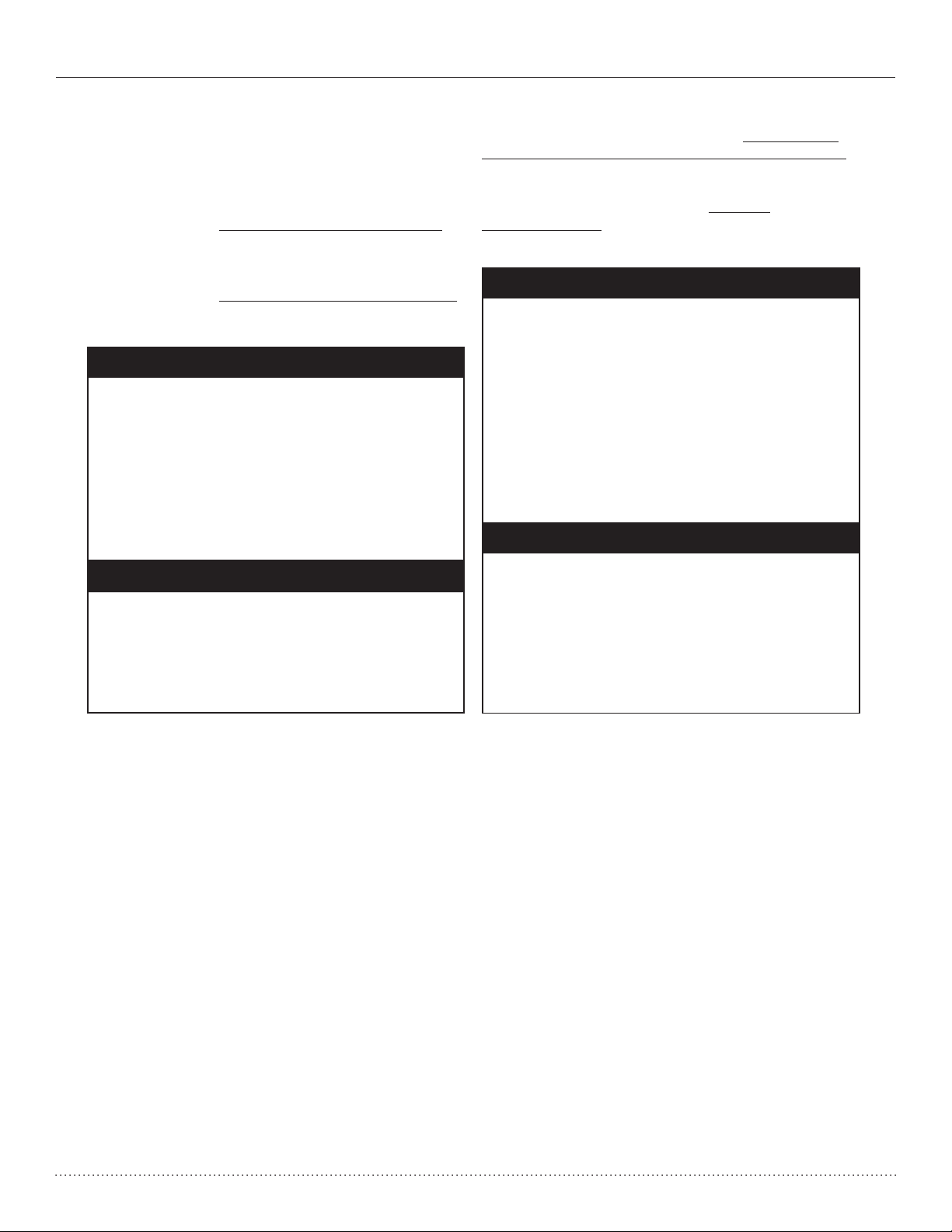
Safety
Warnings, cautions and notices appear throughout this
manual. Read these items carefully before attempting any
installation, service or troubleshooting of the equipment.
DANGER: Indicates an immediate hazardous situation,
which if not avoided will result in death or serious injury.
DANGER labels on unit access panels must be observed.
WARNING: Indicates a potentially hazardous situation,
which if not avoided could result in death or serious injury.
� WARNING! �
WARNING! Verify refrigerant type before
proceeding. Units are shipped with R-22
refrigerant.
R-410A
CAUTION: Indicates a potentially hazardous situation or
an unsafe practice, which if not avoided could result in
minor or moderate injury or product or property damage.
NOTICE: Notification of installation, operation or
maintenance information, which is important, but which is
not hazard-related.
� WARNING! �
WARNING! All refrigerant discharged
from this unit must be recovered WITHOUT
EXCEPTION. Technicians must follow industry
accepted guidelines and all local, state, and
federal statutes for the recovery and disposal of
refrigerants. If a compressor is removed from
this unit, refrigerant circuit oil will remain in the
compressor. To avoid leakage of compressor
oil, refrigerant lines of the compressor must be
sealed after it is removed.
� CAUTION! �
� WARNING! �
WARNING! To avoid the release of
refrigerant into the atmosphere, the
refrigerant circuit of this unit must be
serviced only by technicians who meet local,
state, and federal proficiency requirements.
CAUTION!
To avoid equipment damage,
DO NOT use these units as a source of
heating or cooling during the construction
process. The mechanical components and
filters will quickly become clogged with
construction dirt and debris, which may
cause system damage.
3
Page 5

Heat Controller, Inc. HP SerieS Installation, Operation & Maintenance
6. Loosen compressor bolts on units equipped with
compressor spring vibration isolation until the
compressor rides freely on the springs. Remove
shipping restraints.
7.
REMOVE COMPRESSOR SUPPORT PLATE 1/4”
SHIPPING BOLTS (2 on each side) TO MAXIMIZE
VIBRATION AND SOUND ATTENUATION.
GENERAL INFORMATION
Inspection
Upon receipt of the equipment, carefully check the shipment
against the bill of lading. Make sure all units have been
received. Inspect the packaging of each unit, and inspect
each unit for damage. Insure that the carrier makes proper
notation of any shortages or damage on all copies of the
freight bill and completes a common carrier inspection
report. Concealed damage not discovered during unloading
must be reported to the carrier within 15 days of receipt of
shipment. If not filed within 15 days, the freight company
can deny the claim without recourse. Note: It is the
responsibility of the purchaser to file all necessary claims
with the carrier. Notify Heat Controller of all damage within
fifteen (15) days of shipment.
Storage
Equipment should be stored in its original packaging in
a clean, dry area. Store units in an upright position at all
times. Stack units a maximum of 3 units high.
Unit Protection
Cover units on the job site with either the original packaging
or an equivalent protective covering. Cap the open ends
of pipes stored on the job site. In areas where painting,
plastering, and/or spraying has not been completed, all
due precautions must be taken to avoid physical damage
to the units and contamination by foreign material. Physical
damage and contamination may prevent proper start-up and
may result in costly equipment clean-up.
Examine all pipes, fittings, and valves before installing
any of the system components. Remove any dirt or debris
found in or on these components.
Pre-Installation
Installation, Operation, and Maintenance instructions
Installation, Operation and Maintenance
are provided with each unit. Horizontal equipment is
instructions are provided with each unit. Vertical unit
designed for installation above false ceiling or in a ceiling
congurations are typically installed in a mechanical
plenum. Other unit configurations are typically installed
room. The installation site chosen should include
in a mechanical room. The installation site chosen
adequate ervice clearance around the unit. Before
should include adequate service clearance around the
unit start-up, read all manuals and become familiar
unit. Before unit start-up, read all manuals and become
with the unit and its operation. Thoroughly check the
familiar with the unit and its operation. Thoroughly check
system before operation.
the system before operation.
Prepare units for installation as follows:
1. Compare the electrical data on the unit nameplate
with ordering and shipping information to verify that
the correct unit has been shipped.
2. Keep the cabinet covered with the original packaging
until installation is complete and all plastering,
painting, etc. is finished.
3. Verify refrigerant tubing is free of kinks or dents and
that it does not touch other unit components.
4. Inspect all electrical connections. Connections must
be clean and tight at the terminals.
5. Remove any blower support packaging.
6. Loosen compressor bolts on units equipped with
compressor spring vibration isolation until the
compressor rides freely on the springs. Remove
shipping restraints.
REMOVE COMPRESSOR SUPPORT PLATE 1/4”
7.
7.
8. Some airflow patterns are field convertible (horizontal
SHIPPING BOLTS (2 on each side) TO MAXIMIZE
units only). Locate the airflow conversion section of
VIBRATION AND SOUND ATTENUATION.
this IOM.
8. Some airflow patterns are field convertible (horizontal
9. Locate and verify any hangers, or other accessory
8.
units only). Locate the airflow conversion section of
kits located in the compressor section or blower
this IOM.
section.
9. Locate and verify any hangers, or other accessory
kits located in the compressor section or blower
section.
� CAUTION! �
CAUTION! DO NOT store or install units
in corrosive environments or in locations
subject to temperature or humidity extremes
CAUTION! DO NOT store or install units
(e.g., attics, garages, rooftops, etc.).
in corrosive environments or in locations
Corrosive conditions and high temperature
subject to temperature or humidity extremes
or humidity can significantly reduce
(e.g., attics, garages, rooftops, etc.).
performance, reliability, and service life.
Corrosive conditions and high temperature
Always move units in an upright position.
or humidity can significantly reduce
Tilting units on their sides may cause
performance, reliability, and service life.
equipment damage.
Always move units in an upright position.
� CAUTION! �
Tilting units on their sides may cause
equipment damage.
NOTICE! Failure to remove shipping brackets
from spring-mounted compressors will cause
excessive noise, and could cause component
NOTICE! Failure to remove shipping brackets
failure due to added vibration.
from spring-mounted compressors will cause
excessive noise, and could cause component
failure due to added vibration.
� CAUTION! �
CAUTION! CUT HAZARD - Failure to follow
this caution may result in personal injury.
Sheet metal parts may have sharp edges
CAUTION! CUT HAZARD - Failure to follow
or burrs. Use care and wear appropriate
this caution may result in personal injury.
protective clothing, safety glasses and
Sheet metal parts may have sharp edges
gloves when handling parts and servicing
or burrs. Use care and wear appropriate
heat pumps.
protective clothing, safety glasses and
gloves when handling parts and servicing
heat pumps.
� CAUTION! �
4
Page 6
Installation, Operation & Maintenance HP SerieS Heat Controller, Inc.
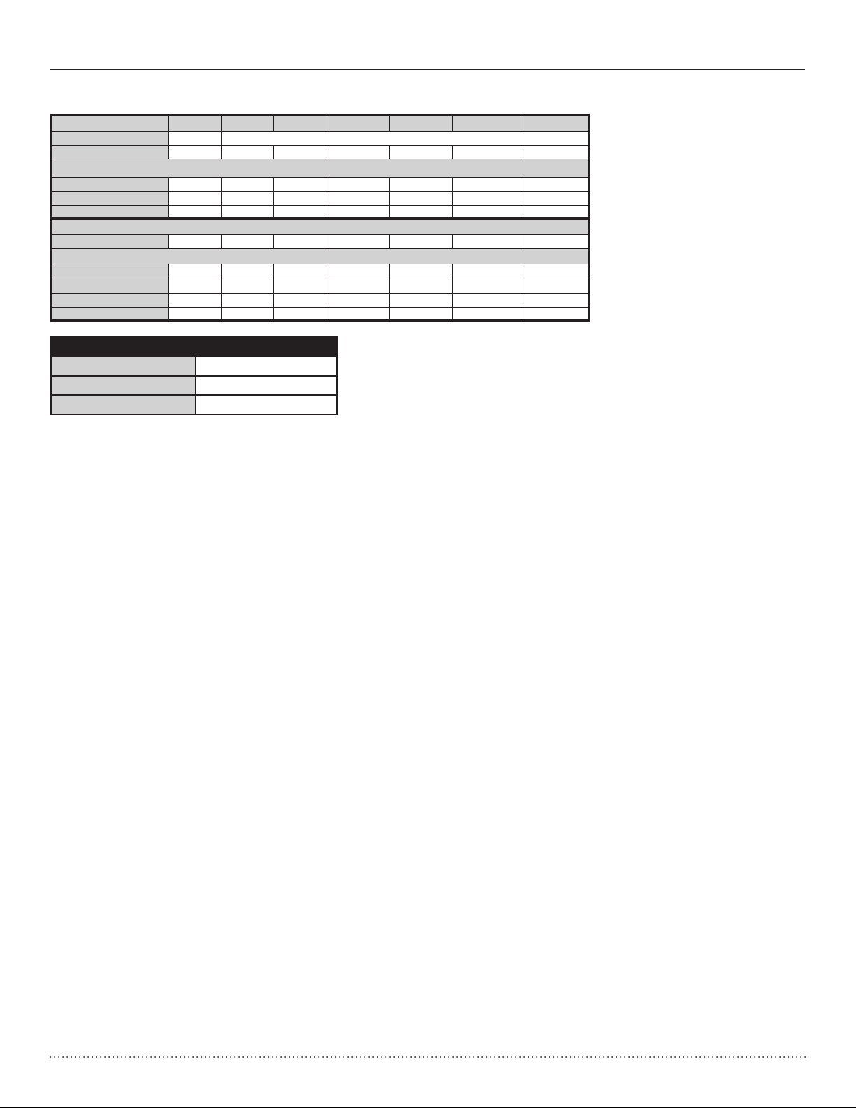
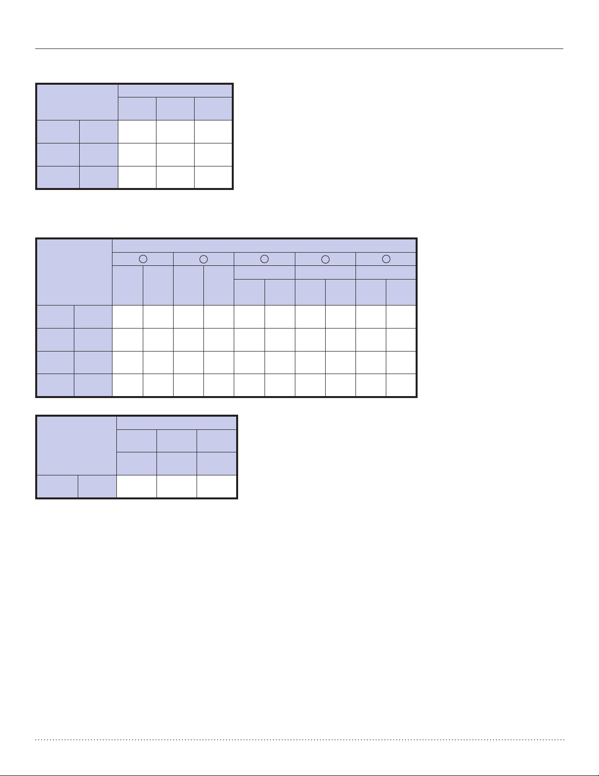
Physical Data
HP Series
Compressor (1 Each) Rotary Scroll
Factory Charge R410A (oz) 43 43 48 50 70 74 82
PSC Fan Motor & Blower
Fan Motor Type/Speeds PSC/3 PSC/3 PSC/3 PSC/3 PSC/3 PSC/3 PSC/3
Fan Motor (hp) 1/6 1/4 3/4 1/2 3/4 3/4 1
Blower Wheel Size (Dia x w) 8x7 9x7 9x7 9x8 9x8 10x10 11x10
Water Connection Size 1” Swivel
Hx Water Volume (gal.) .45 .286 .323 .323 .890 .738 .939
Vertical
Air Coil Dimensions (H x W) 20x17.25 20x17.25 20x17.25 24x21.75 24x21.76 28x25 28x25
Filter Standard - 1" Throwaway 20x20 20x20 20x20 24x24 24x24 28x28 28x28
Weight - Operating (lbs.) 168 184 192 213 228 283 298
Weight - Packaged (lbs.) 173 194 197 219 234 290
018 024 030 036 042 048 060
305
Maximum Working Water Pressure
Pressure PSIG (kPa)
Unit Source Circuit 500 (3,447)
HWG Circuit 125 (862)
5
Page 7
Heat Controller, Inc. HP SerieS Installation, Operation & Maintenance
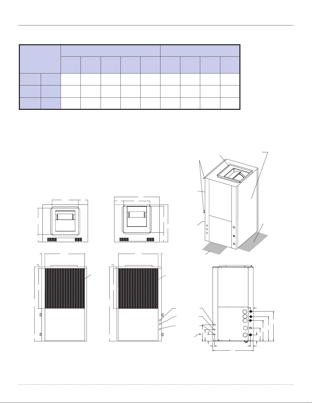
HP - Vertical Upow Dimensional Data
Vertical
uplow
Model
018 - 030
036 - 042
048 - 060
Vertical
Upow
Model
018
024 -
030
036 -
042
048 -
060
in
cm
in
cm
in
cm
in
cm
in
cm
in
cm
in
cm
Overall Cabinet
A
WidthBDepthCHeight
22.4
56.9
22.4
56.9
25.4
64.5
Loop
In
D
3.7
9.4
3.7
9.4
3.7
9.4
3.7
9.4
22.4
56.9
25.4
64.5
29.1
73.9
1 2 3 4 5
Loop
In
E
1.9
4.8
1.9
4.8
1.8
4.6
1.8
4.6
40.5
102.9
46.5
118.1
50.5
128.3
Water Connections - Standard Units
Loop
Out
F
9.7
24.6
9.7
24.6
12.7
32.3
12.7
32.3
Loop
Out
E
1.9
4.8
1.9
4.8
1.8
4.6
1.8
4.6
Cond. 3/4” HWG In HWG Out
H I DD EE FF EE
7.0
17.8
7.0
17.8
8.0
20.3
8.0
20.3
1.9
4.8
1.9
4.8
1.8
4.6
1.8
4.6
11.7
29.7
12.4
31.5
15.2
38.6
15.2
38.6
1.6
4.1
1.6
4.1
1.6
4.1
1.6
4.1
14.9
37.8
15.7
39.9
18.4
46.7
18.4
46.7
1.6
4.1
1.6
4.1
1.6
4.1
1.6
4.1
Electrical Knockouts
Vertical
018 - 060
Model
in
cm
J
1/2”
Low
Voltage
4.0
10.2
K
1/2”
Low
Voltage
7.0
17.8
L
3/4”
Power
Supply
10.0
25.4
Notes:
1. While clear access to all removable panels is not required, installer should take care to comply with all building codes and allow
adequate clearance for future eld service.
2. Front & Side access is preferred for service access. However, all components may be serviced from the front access panel if side
access is not available.
3. Discharge ange is eld installed.
4. Condensate is 3/4” socket.
5. Source water and optional HWG connections are 1” swivel.
6
Page 8
Installation, Operation & Maintenance HP SerieS Heat Controller, Inc.
HP - Vertical Upow Dimensional Data
Vertical
Model
018 - 030
036 - 042
048 - 060
in
cm
in
cm
in
cm
Duct Flange Installed (+/- 0.10 in, +/- 2.5mm)
M N
7.2
18.3
7.2
18.3
8.2
20.8
Legend:
CAP = Control Access Panel
BSP = Blower Service Panel
CSP = Compressor Access Panel
ASP = Alternative Service Panel
P
Discharge Connection
Supply
Width
4.2
10.7
6.0
15.2
5.7
14.5
14.0
35.6
14.0
35.6
16.0
40.6
N
Return Connection
Using Return Air Opening
O
N
P
Supply
Depth
14.0
35.6
14.0
35.6
18.0
45.7
B
P
Q R
5.4
13.7
5.2
13.2
5.2
13.2
2.2
5.6
2.1
5.3
2.1
5.3
S
Return
Depth
Return
Height
18.4
46.7
22.9
58.2
26.2
66.5
Standard Filter Bracket
Air Coil
T
20.3
51.6
24.3
61.7
28.3
71.9
Field Installed
Discharge Flange
U
1.1
2.8
1.1
2.8
1.1
2.8
Access Panels
BSP
ASP
Front
O
Q
Top View-Right Return
R
U
T
C
Right Return Right View
- Air Coil Opening
Air Coil Side
S
Opptional
2' [61cm]
Service
Access
Left Rtn
(Right Rtn
Opposite
Side)
Air Coil Side
Top View-Left Return
S
O
Front
M
R
A
CSP
2' [61cm]
Service
CAP
Isometric
View
U
Air Coil
Air Coil
T
C
Power Supply
3/4" [19.1 mm] HV
Knockout
Low Voltage
1/2" [12.7 mm] LV
Knockout
CSPCSP
BackFront
Left Return Left View
- Air Coil Opening
FrontBack
Low Voltage
1/2" [12.7 mm] LV
Knockout
CSP
L
K
J
U
A
EE
5
4
3
2
2
3
1
D
FF
DD
F
H
E
7
Page 9
Heat Controller, Inc. HP SerieS Installation, Operation & Maintenance
VERTICAL INSTALLATION
Vertical Unit Location
Units are not designed for outdoor installation. Locate
the unit in an INDOOR area that allows enough space
for service personnel to perform typical maintenance or
repairs without removing unit from the mechanical room/
closet. Vertical units are typically installed in a mechanical
room or closet. Never install units in areas subject to
freezing or where humidity levels could cause cabinet
condensation (such as unconditioned spaces subject
to 100% outside air). Consideration should be given to
access for easy removal of the filter and access panels.
Provide sufficient room to make water, electrical, and
duct connection(s).
If the unit is located in a confined space, such as a closet,
provisions must be made for return air to freely enter
the space by means of a louvered door, etc. Any access
panel screws that would be difficult to remove after the
unit is installed should be removed prior to setting the
unit. Refer to Figures 7 and 8 for typical installation
illustrations. Refer to unit specifications catalog for
dimensional data.
1. Install the unit on a piece of rubber, neoprene or
other mounting pad material for sound isolation. The
pad should be at least 3/8” [10mm] to 1/2” [13mm] in
thickness. Extend the pad beyond all four edges of the
unit.
2. Provide adequate clearance for filter replacement
and drain pan cleaning. Do not block filter access
with piping, conduit or other materials. Refer to unit
specifications for dimensional data.
3. Provide access for fan and fan motor maintenance
and for servicing the compressor and coils without
removing the unit.
4. Provide an unobstructed path to the unit within the
closet or mechanical room. Space should be sufficient
to allow removal of the unit, if necessary.
5. Provide access to water valves and fittings and
screwdriver access to the unit side panels, discharge
collar and all electrical connections.
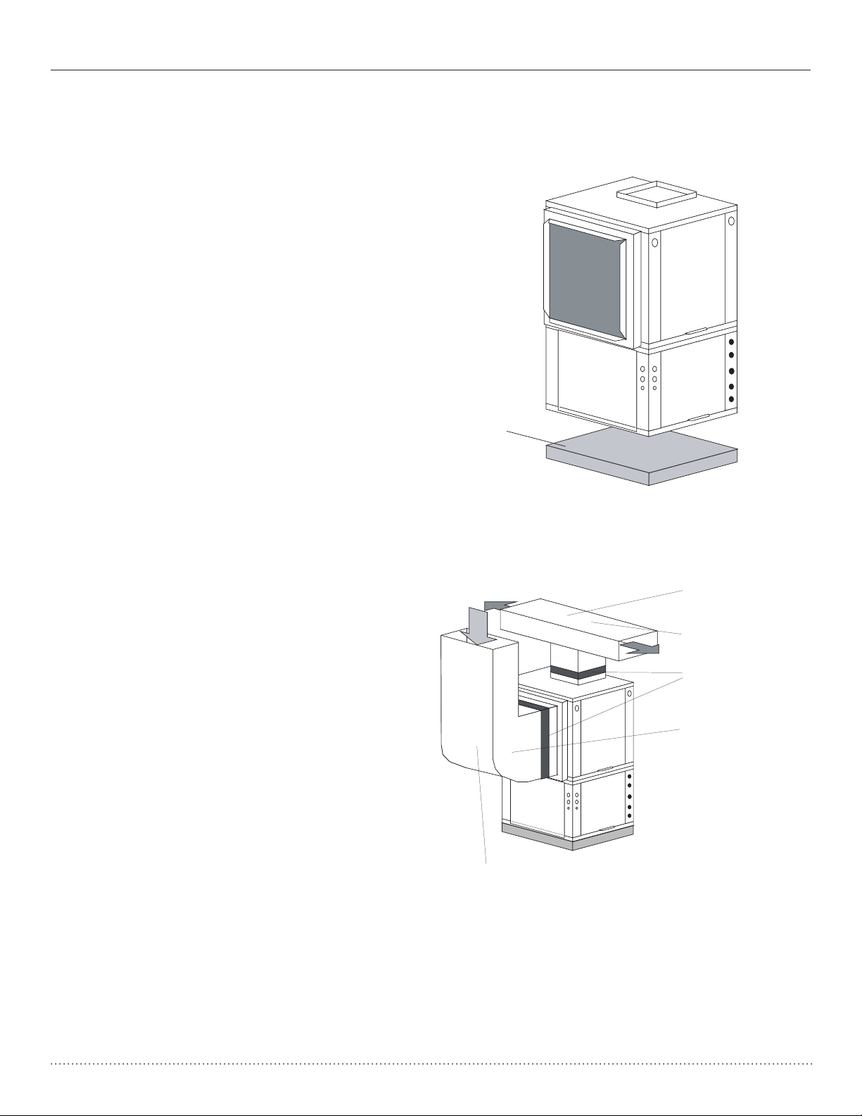
Figure 7: Vertical Unit Mounting
Air Pad or Extruded
polystyrene insulation board
Figure 8: Typical Vertical Unit Installation
Using Ducted Return Air
Internally insulate supply
duct for first 4’ [1.2m] each
way to reduce noise
Use turning vanes in
supply transition
Flexible canvas duct
connector to reduce
noise and vibration
Rounded return
transition
The installation of water source heat pump units and all
associated components, parts and accessories which
make up the installation shall be in accordance with
the regulations of ALL authorities having jurisdiction
and MUST conform to all applicable codes. It is the
responsibility of the installing contractor to determine and
comply with ALL applicable codes and regulations.
Internally insulate return
transition duct to reduce
noise
8
Rev 3/27/00
Page 10
Installation, Operation & Maintenance HP SerieS Heat Controller, Inc.
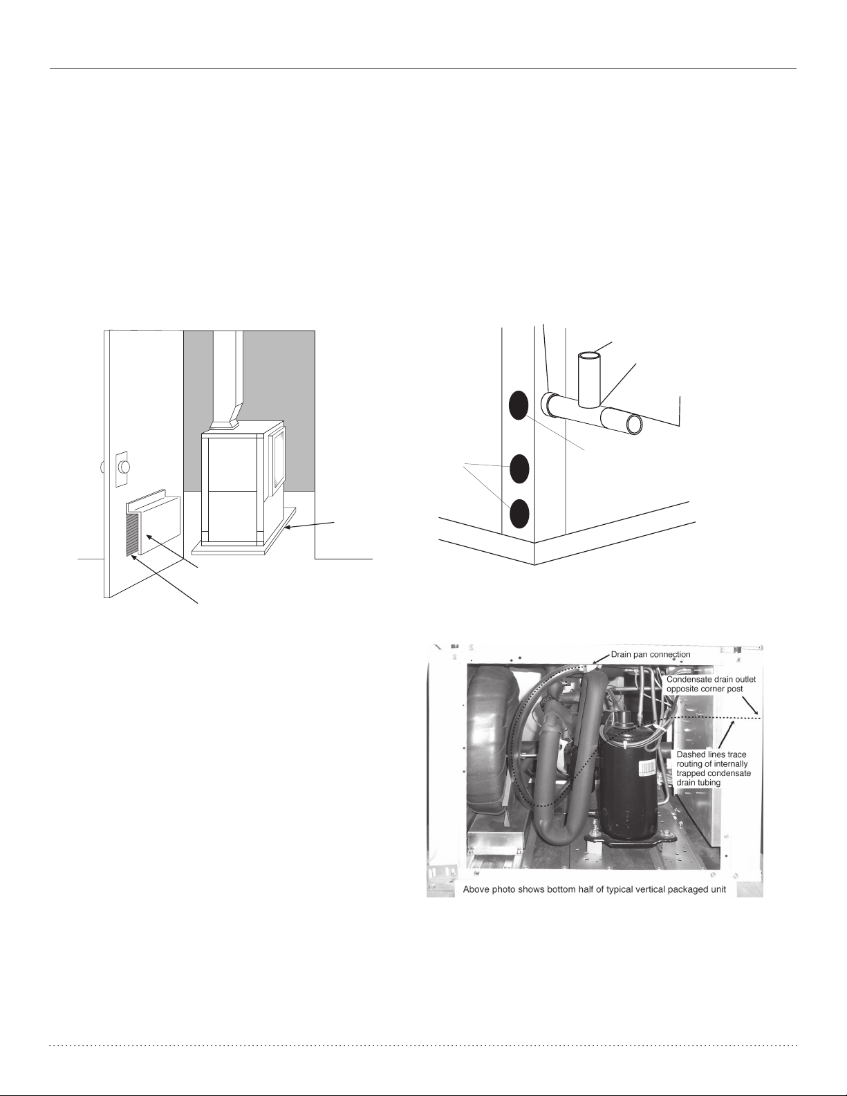
VERTICAL INSTALLATION
Sound Attenuation for Vertical Units
Sound attenuation is achieved by enclosing the unit
within a small mechanical room or a closet. Additional
measures for sound control include the following:
1. Mount the unit so that the return air inlet is 90° to
the return air grille. Refer to Figure 9. Install a sound
baffle as illustrated to reduce line-of sight sound
transmitted through return air grilles.
2.
Mount the unit on a rubber or neoprene isolation pad to
minimize vibration transmission to the building structure.
Figure 9: Vertical Sound Attenuation
Condensate Piping – Vertical Units
Vertical units utilize a condensate hose inside the
cabinet as a trapping loop; therefore an external trap
is not necessary. Figure 10a shows typical condensate
connections. Figure 10b illustrates the internal trap for
a typical vertical heat pump. Each unit must be installed
with its own individual vent and a means to flush or blow
out the condensate drain line. Do not install units with a
common trap and/or vent.
Figure 10a: Vertical Condensate Drain
1/4” per foot (21mm per m)
slope to drain
Figure 10b: Vertical Internal Condensate Trap
9
Page 11
Heat Controller, Inc. HP SerieS Installation, Operation & Maintenance
WATER CONNECTION INSTALLATION
External Flow Controller Mounting
The Flow Controller can be mounted beside the unit
as shown in Figure 12. Review the Flow Controller
installation manual for more details.
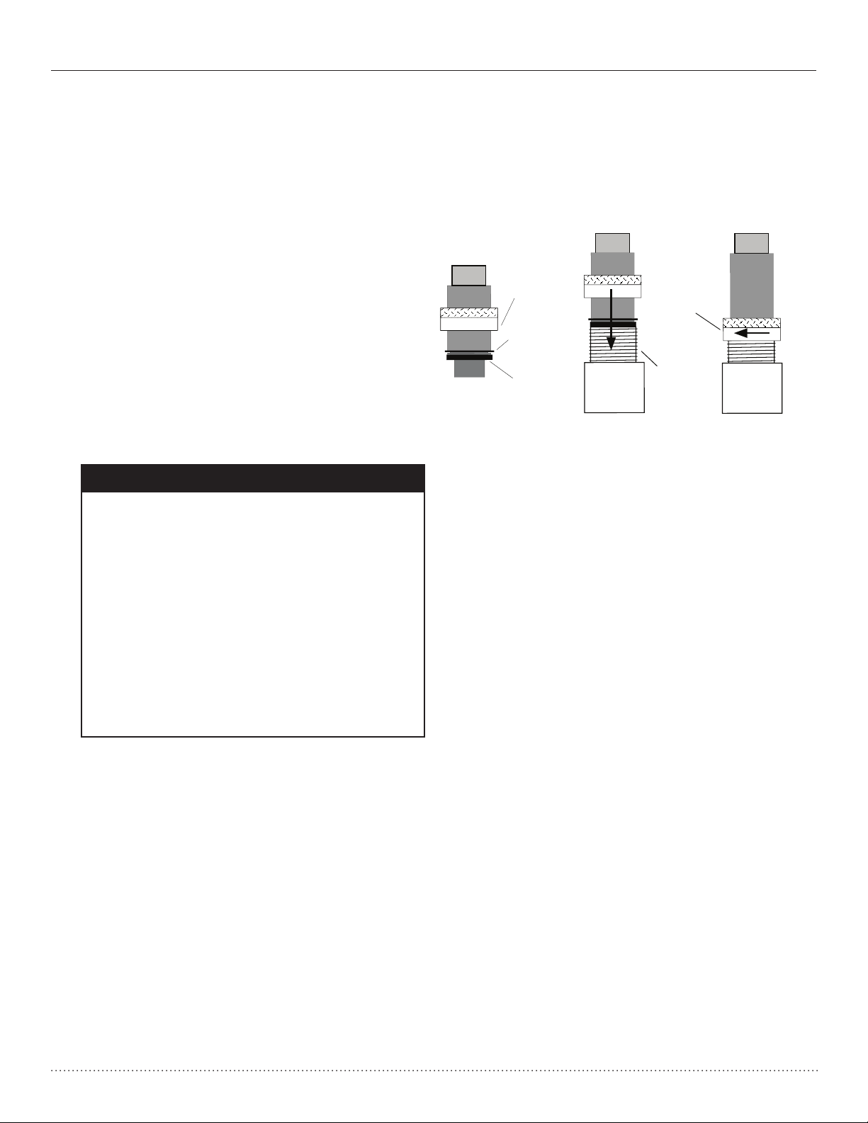
Water Connections-Residential HR Models
Models utilize swivel piping fittings for water connections
that are rated for 450 psi (3101 kPa) operating pressure.
The connections have a rubber gasket seal similar to a
garden hose gasket, which when mated to the flush end
of most 1” threaded male pipe fittings provides a leakfree seal without the need for thread sealing tape or joint
compound. Insure that the rubber seal is in the swivel
connector prior to attempting any connection (rubber
seals are shipped attached to the swivel connector). DO
NOT OVER TIGHTEN or leaks may occur.
The female locking ring is threaded onto the pipe threads
HP
GROUND-LOOP HEAT PUMP APPLICATIONS
� CAUTION! �
CAUTION! The following instructions
represent industry accepted installation
practices for closed loop earth coupled heat
pump systems. Instructions are provided
to assist the contractor in installing trouble
free ground loops. These instructions are
recommendations only. State/provincial
and local codes MUST be followed and
installation MUST conform to ALL applicable
codes. It is the responsibility of the installing
contractor to determine and comply with ALL
applicable codes and regulations.
Pre-Installation
Prior to installation, locate and mark all existing
underground utilities, piping, etc. Install loops for new
construction before sidewalks, patios, driveways, and other
construction has begun. During construction, accurately
mark all ground loop piping on the plot plan as an aid in
avoiding potential future damage to the installation.
Piping Installation
The typical closed loop ground source system is shown
in Figure 12. All earth loop piping materials should be
limited to polyethylene fusion only for in-ground sections
of the loop. Galvanized or steel fittings should not be
used at any time due to their tendency to corrode. All
plastic to metal threaded fittings should be avoided due
to their potential to leak in earth coupled applications. A
flanged fitting should be substituted. P/T plugs should be
used so that flow can be measured using the pressure
drop of the unit heat exchanger.
which holds the male pipe end against the rubber
gasket, and seals the joint. HAND TIGHTEN ONLY! DO
NOT OVERTIGHTEN!
Figure 11: Water Connections
Hand Tighten
Only!
Swivel Nut
Stainless steel
snap ring
Gasket
Earth loop temperatures can range between 25 and
110°F [-4 to 43°C]. Flow rates between 2.25 and 3 gpm
per ton [2.41 to 3.23 l/m per kW] of cooling capacity
recommended in these applications.
Test individual horizontal loop circuits before backfilling.
Test vertical U-bends and pond loop assemblies prior to
installation. Pressures of at least 100 psi [689 kPa] should
be used when testing. Do not exceed the pipe pressure
rating. Test entire system when all loops are assembled.
Flushing the Loop
Once piping is completed between the unit, Flow
Controller and the ground loop (Figure 12), the loop is
ready for final purging and charging. A flush cart with
at least a 1.5 hp [1.1 kW] pump is required to achieve
enough fluid velocity in the loop piping system to purge
air and dirt particles. An antifreeze solution is used in
most areas to prevent freezing. All air and debris must
be removed from the earth loop piping before operation.
Flush the loop with a high volume of water at a minimum
velocity of 2 fps (0.6 m/s) in all piping. The steps below
must be followed for proper flushing.
1. Fill loop with water from a garden hose through the
flush cart before using the flush cart pump to insure
an even fill.
2. Once full, the flushing process can begin. Do not
allow the water level in the flush cart tank to drop
below the pump inlet line to avoid air being pumped
back out to the earth loop.
3. Try to maintain a fluid level in the tank above the
return tee so that air cannot be continuously mixed
back into the fluid. Surges of 50 psi (345 kPa) can
be used to help purge air pockets by simply shutting
off the return valve going into the flush cart reservoir.
This “dead heads” the pump to 50 psi (345 kPa). To
purge, dead head the pump until maximum pumping
Do Not
Overtighten!
Brass Adaptor
10
Page 12
Installation, Operation & Maintenance HP SerieS Heat Controller, Inc.
GROUND-LOOP HEAT PUMP APPLICATIONS
pressure is reached. Open the return valve and a
pressure surge will be sent through the loop to help
purge air pockets from the piping system.
4. Notice the drop in fluid level in the flush cart tank
when the return valve is shut off. If air is adequately
purged from the system, the level will drop only 1-2
inches (2.5 - 5 cm) in a 10” (25 cm) diameter PVC
flush tank (about a half gallon [2.3 liters]), since
liquids are incompressible. If the level drops more
than this, flushing should continue since air is still
being compressed in the loop fluid. Perform the “dead
head” procedure a number of times.
Note: This fluid level drop is your only indication of air in
the loop.
Antifreeze may be added before, during or after the
flushing procedure. However, depending upon which time
is chosen, antifreeze could be wasted when emptying the
flush cart tank. See antifreeze section for more details.
Loop static pressure will fluctuate with the seasons.
Pressures will be higher in the winter months than during
the cooling season. This fluctuation is normal and should
be considered when charging the system initially. Run the
unit in either heating or cooling for a number of minutes to
condition the loop to a homogenous temperature. This is
a good time for tool cleanup, piping insulation, etc. Then,
perform final flush and pressurize the loop to a static
pressure of 50-75 psi [345-517 kPa] (winter) or 35-40 psi
[241-276 kPa] (summer). After pressurization, be sure
to loosen the plug at the end of the Grundfos loop pump
motor(s) to allow trapped air to be discharged and to insure
the motor housing has been flooded. This is not required
for Taco circulators. Insure that the Flow Controller provides
adequate flow through the unit by checking pressure drop
across the heat exchanger and compare to the pressure
drop tables at the back of the manual.
Antifreeze
In areas where minimum entering loop temperatures drop
below 40°F [5°C] or where piping will be routed through
areas subject to freezing, antifreeze is required. Alcohols
and glycols are commonly used as antifreeze; however
your local sales manager should be consulted for the
antifreeze best suited to your area. Freeze protection
should be maintained to 15°F [9°C] below the lowest
expected entering loop temperature. For example, if
30°F [-1°C] is the minimum expected entering loop
temperature, the leaving loop temperature would be 25 to
22°F [-4 to -6°C] and freeze protection should be at 15°F
[-10°C]. Calculation is as follows:
30°F - 15°F = 15°F [-1°C - 9°C = -10°C].
All alcohols should be premixed and pumped from
a reservoir outside of the building when possible or
introduced under the water level to prevent fumes.
Calculate the total volume of fluid in the piping system.
Then use the percentage by volume shown in Table
1 for the amount of antifreeze needed. Antifreeze
concentration should be checked from a well mixed
sample using a hydrometer to measure specific gravity.
Low Water Temperature Cutout Setting
CXM Control
When antifreeze is selected, the FP1 jumper (JW3)
should be clipped to select the low temperature (antifreeze 13°F [-10.6°C]) set point and avoid nuisance
faults (see “Low Water Temperature Cutout Selection” in
this manual). NOTE: Low water temperature operation
requires extended range equipment.
Table 1: Approximate Fluid Volume (gal.)
per 100' of Pipe
Fluid Volume (gal [L]/100’ Pipe)
Pipe Size Volume (gal) [L]
1” 4.1 [15.5]
Copper
Rubber Hose 1” 3.9 [14.8]
Polyethylene
Unit Heat Exchanger Typical 1.0 [3.8]
Flush Cart Tank
1.25” 6.4 [24.2]
2.5” 9.2 [34.8]
3/4” IPS SDR11 2.8 [10.6]
1” IPS SDR11
1.25” IPS SDR11 8.0 [30.3]
1.5” IPS SDR11 10.9 [41.3]
2” IPS SDR11 18.0 [68.1]
1.25” IPS SCH40 8.3 [31.4]
1.5” IPS SCH40 10.9 [41.3]
2” IPS SCH40 17.0 [64.4]
10” Dia x 3ft
[254mm x 0.9m]
4.5 [17.0]
10 [37.9]
Table 2: Antifreeze Percentages by Volume
Table 3. Antifreeze Percentages by Volume
Type Minimum Temperature for Freeze Protection
10°F [-12.2
Methanol 25% 21% 16% 10%
100% USP food grade Propylene Glycol 38% 30% 22% 15%
°C] 15°F [-9.4°C] 20°F [-6.7°C] 25°F [-3.9°C]
11
Page 13
Heat Controller, Inc. HP SerieS Installation, Operation & Maintenance
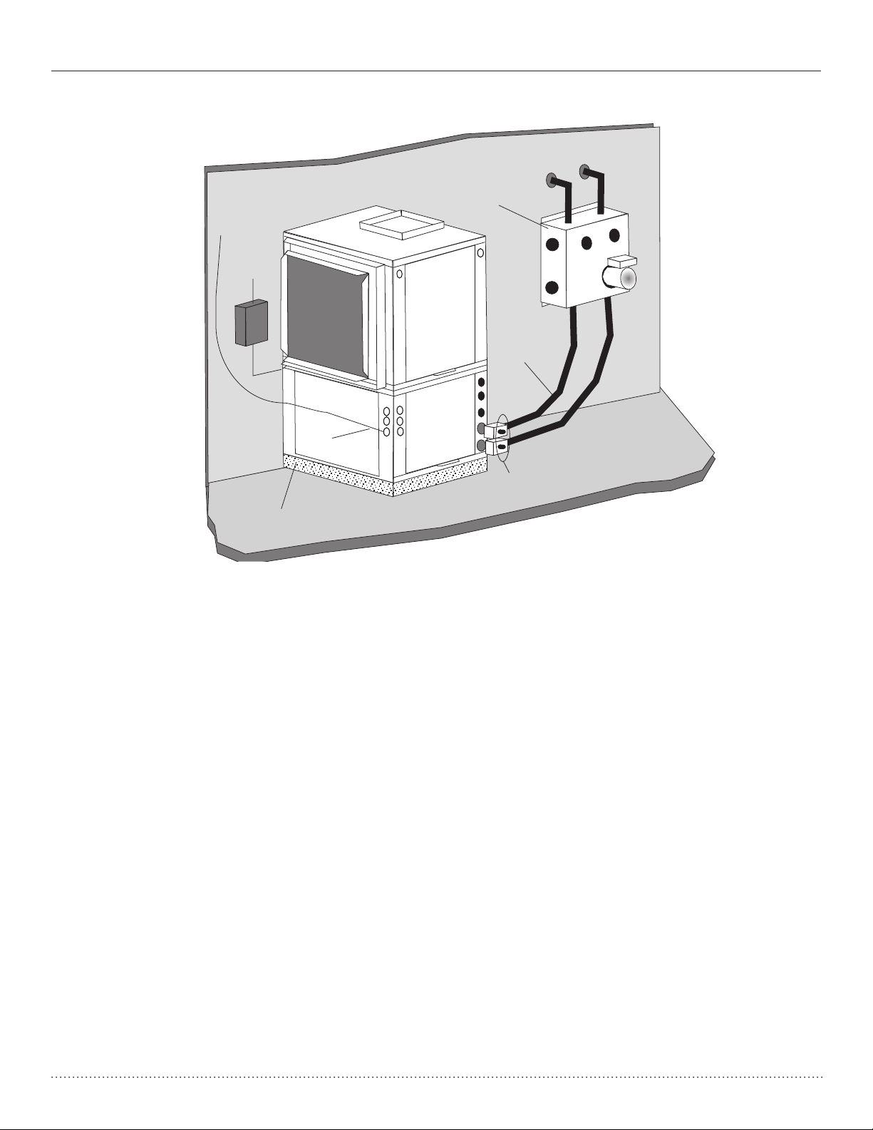
GROUND-LOOP HEAT PUMP APPLICATIONS
Figure 12: Typical Ground-Loop Application
Flow
Controller
Unit Power
Disconnect
Insulated
Hose Kit
Thermostat
Wiring
Air Pad or Extruded
polystyrene insulation
board
GROUND-WATER HEAT PUMP APPLICATIONS
Open Loop - Ground Water Systems
Typical open loop piping is shown in Figure 14. Shut off
valves should be included for ease of servicing. Boiler
drains or other valves should be “tee’d” into the lines to
allow acid flushing of the heat exchanger. Shut off valves
should be positioned to allow flow through the coax via
the boiler drains without allowing flow into the piping
system. P/T plugs should be used so that pressure drop
and temperature can be measured. Piping materials
should be limited to copper or PVC SCH80. Note: Due to
the pressure and temperature extremes, PVC SCH40
is not recommended.
Water quantity should be plentiful and of good quality.
Consult table 3 for water quality guidelines. The unit can
be ordered with either a copper or cupro-nickel water
heat exchanger. Consult Table 3 for recommendations.
Copper is recommended for closed loop systems and
open loop ground water systems that are not high
in mineral content or corrosiveness. In conditions
anticipating heavy scale formation or in brackish water, a
cupro-nickel heat exchanger is recommended. In ground
water situations where scaling could be heavy or where
biological growth such as iron bacteria will be present, an
open loop system is not recommended. Heat exchanger
coils may over time lose heat exchange capabilities due
to build up of mineral deposits. Heat exchangers must
13.
P/T Plugs
only be serviced by a qualified technician, as acid and
special pumping equipment is required. Desuperheater
coils can likewise become scaled and possibly plugged.
In areas with extremely hard water, the owner should be
informed that the heat exchanger may require occasional
acid flushing. In some cases, the desuperheater option
should not be recommended due to hard water conditions
and additional maintenance required.
Water Quality Standards
Table 3 should be consulted for water quality
requirements. Scaling potential should be assessed using
the pH/Calcium hardness method. If the pH <7.5 and the
calcium hardness is less than 100 ppm, scaling potential
is low. If this method yields numbers out of range of those
listed, the Ryznar Stability and Langelier Saturation
indecies should be calculated. Use the appropriate
scaling surface temperature for the application, 150°F
[66°C] for direct use (well water/open loop) and
desuperheater; 90°F [32°F] for indirect use. A monitoring
plan should be implemented in these probable scaling
situations. Other water quality issues such as iron fouling,
corrosion prevention and erosion and clogging should be
referenced in Table 3.
12
Page 14
Installation, Operation & Maintenance HP SerieS Heat Controller, Inc.
GROUND-WATER HEAT PUMP APPLICATIONS
Expansion Tank and Pump
Use a closed, bladder-type expansion tank to minimize
mineral formation due to air exposure. The expansion
tank should be sized to provide at least one minute
continuous run time of the pump using its drawdown
capacity rating to prevent pump short cycling. Discharge
water from the unit is not contaminated in any manner
and can be disposed of in various ways, depending on
local building codes (e.g. recharge well, storm sewer,
drain field, adjacent stream or pond, etc.). Most local
codes forbid the use of sanitary sewer for disposal.
Consult your local building and zoning department to
assure compliance in your area.
Water Control Valve
Note the placement of the water control valve in
13.
Figure 14. Always maintain water pressure in the heat
exchanger by placing the water control valve(s) on the
discharge line to prevent mineral precipitation during
the off-cycle. Pilot operated slow closing valves are
recommended to reduce water hammer. If water hammer
persists, a mini-expansion tank can be mounted on the
piping to help absorb the excess hammer shock. Insure
that the total ‘VA’ draw of the valve can be supplied by
the unit transformer. For instance, a slow closing valve
can draw up to 35VA. This can overload smaller 40 or
50 VA transformers depending on the other controls in
the circuit. A typical pilot operated solenoid valve draws
approximately 15VA.
Flow Regulation
Flow regulation can be accomplished by two methods.
One method of flow regulation involves simply adjusting
the ball valve or water control valve on the discharge
line. Measure the pressure drop through the unit heat
exchanger, and determine flow rate from Tables 8. Since
Table 10C. Since
the pressure is constantly varying, two pressure gauges
may be needed. Adjust the valve until the desired flow of
1.5 to 2 gpm per ton [2.0 to 2.6 l/m per kW] is achieved.
A second method of flow control requires a flow control
device mounted on the outlet of the water control valve.
The device is typically a brass fitting with an orifice of
rubber or plastic material that is designed to allow a
specified flow rate. On occasion, flow control devices may
produce velocity noise that can be reduced by applying
some back pressure from the ball valve located on the
discharge line. Slightly closing the valve will spread the
pressure drop over both devices, lessening the velocity
noise. NOTE: When EWT is below 50°F [10°C], 2 gpm
per ton (2.6 l/m per kW) is required.
Water Coil Low Temperature Limit Setting
For all open loop systems the 30°F [-1.1°C] FP1 setting
(factory setting-water) should be used to avoid freeze
damage to the unit. See “Low Water Temperature Cutout
Selection” in this manual for details on the low limit setting.
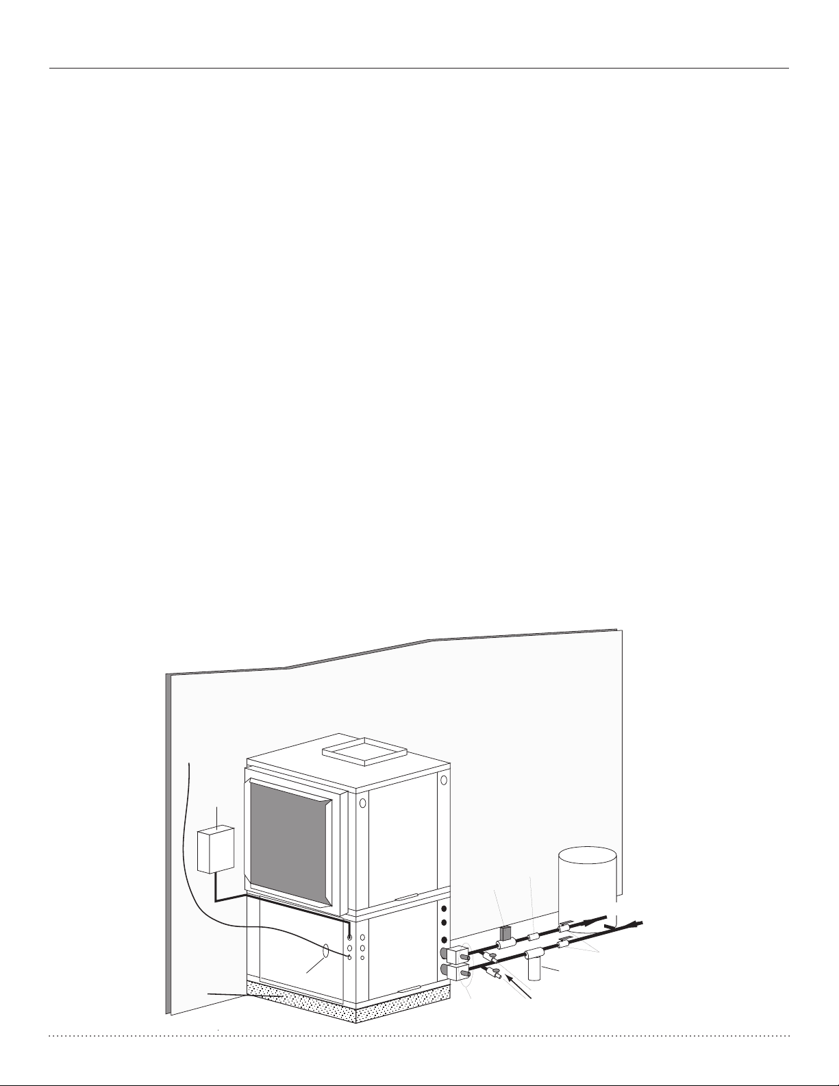
Figure 13: Typical Open Loop/Well Application
Unit Power
Disconnect
Air Pad or
Extruded
polystyrene
insulation board
Thermostat
Wiring
Water
Control
Valve
P/T Plugs
Flow
Regulator
Boiler
Drains
Pressure
Tank
Water Out
Optional
Filter
Water In
Shut-Off
Valve
13
Page 15

Heat Controller, Inc. HP SerieS Installation, Operation & Maintenance
WATER QUALITY STANDARDS
Table 3: Water Quality Standards
Water Quality
Parameter
Heat
Exchanger
Closed Loop
Recirculating
Open Loop and Recirculating Well
Material
Scaling Potential - Primary Measurement
Above the given limits, scaling is likely to occur. Scaling indexes should be calculated using the limits below.
pH/Calcium Hardness All - pH < 7.5 and Ca Hardness <100ppm
Method
Index Limits for Probable Scaling Situations -
Scaling indexes should be calculated at 150°F for direct use and Hot water generator applications,
and at 90°F for indirect HX use. A monitoring plan should be implemented.
Ryznar All - 6.0 - 7.5
Stability Index If >7.5 minimize steel pipe use.
Langelier All - -0.5 to +0.5
Saturation Index
(Operation outside these limits is not recommended)
If <-0.5 minimize steel pipe use. Based upon 150 °F HWG and Direct
well, 85°F Indirect Well HX
Iron Fouling
Iron Fe2+(Ferrous)
(Bacterial Iron potential)
Iron Fouling All - <0.5 ppm of Oxygen
All - <0.2 ppm (Ferrous)
2+
(ferrous)>0.2 ppm with pH 6 - 8, O2<5 ppm check for iron bacteria
If Fe
Above this level deposition will occur.
Corrosion Prevention
pH All 6 - 8.5 6 - 8.5
Monitor/treat as
needed
Hydrogen Sulfide (H2S) All - <0.5 ppm
Ammonia ion All - <0.5 ppm
as hydroxide, chloride,
nitrate and sulfate
compounds
Maximum Maximum Allowable at maximum water temperature.
Chloride Levels
Copper - <20ppm NR NR
CuproNickel - <150 ppm NR NR
304 SS - <400 ppm <250 ppm <150 ppm
316 SS - <1000 ppm <550 ppm < 375 ppm
Titanium - >1000 ppm >550 ppm >375 ppm
Minimize steel pipe below 7 and no open tanks with pH <8
At H2S>0.2 ppm, avoid use of copper and copper nickel piping or HX's.
Copper alloy (bronze or brass) cast components are OK to <0.5 ppm.
50°F (10°C) 75°F (24°C) 100°F (38°C)
Rotten egg smell appears at 0.5 ppm level.
Erosion and Clogging
<10 ppm of particles
Particulate Size and
Erosion
Notes:
• Closed Recirculating system is identified by a
• NR - Application not recommended.
• "-" No design Maximum.
All
and a maximum
velocity of 6 fps.
Filtered for maximum
800 micron size.
closed pressurized piping system. Recirculating open wells should observe the open recirculating design considerations.
<10 ppm (<1 ppm "sandfree" for reinjection) of particlesand a maximum
velocity of 6 fps. Filtered for maximum 800 micron size. Any particulate
that is not removed can potentially clog components.
Rev.: 04/04/04
14
Page 16

Installation, Operation & Maintenance HP SerieS Heat Controller, Inc.
Dual element electric water heaters are recommended.
If a gas, propane, oil or electric water heater with a
single element is used, a second preheat storage tank
is recommended to insure a usuable entering water
temperature for the HWG.
15
Page 17

Heat Controller, Inc. HP SerieS Installation, Operation & Maintenance
SCALD VALVE AT THE HOT WATER STORAGE TANK
WITH SUCH VALVE PROPERLY SET TO CONTROL
WATER TEMPERATURES DISTRIBUTED TO ALL HOT
WATER OUTLETS AT A TEMPERATURE LEVEL THAT
PREVENTS SCALDING OR BURNS.
16
Page 18

Installation, Operation & Maintenance HP SerieS Heat Controller, Inc.
!
WARNING!
The HWG pump is fully wired from the factory. Use extreme
caution when working around the mircoprocessor control as it
contains line voltage connections that presents a shock hazard
that can cause severe injury or death!
!
17
Page 19

Heat Controller, Inc. HP SerieS Installation, Operation & Maintenance
ELECTRICAL - LINE VOLTAGE
� WARNING! �
WARNING! To avoid possible injury or death
due to electrical shock, open the power
supply disconnect switch and secure it in an
open position during installation.
� CAUTION! �
CAUTION!
Use only copper conductors for field
All field installed wiring, including electrical ground, must
comply with the National Electrical Code as well as all
applicable local codes. Refer to the unit electrical data for
fuse sizes. Consult wiring diagram for field connections
that must be made by the installing (or electrical)
contractor.
All final electrical connections must be made with a
length of flexible conduit to minimize vibration and sound
transmission to the building.
installed electrical wiring. Unit terminals are not
Electrical - Line Voltage
designed to accept other types of conductors.
General Line Voltage Wiring
Be sure the available power is the same voltage and
phase shown on the unit serial plate. Line and low voltage
wiring must be done in accordance with local codes or the
National Electric Code, whichever is applicable.
Electrical Data -
HP
Model
018 G 208-230/60/1 197/254 7.2 33.0 1 0.4 1.00 4.0 12.6 14.4 20
024 G 208-230/60/1 197/254 12.8 58.3 1 0.4 1.50 4.0 18.7 21.9 30
030 G 208-230/60/1 197/254 14.1 73.0 1 0.4 3.00 4.0 21.5 25.0 35
036 G 208-230/60/1 197/254 16.7 79.0 1 0.4 1.80 4.0 22.9 27.1 40
042 G 208-230/60/1 197/254 17.9 112.0 1 0.4 3.00 4.0 25.3 29.8 45
048 G 208-230/60/1 197/254 21.8 117.0 1 0.4 3.40 4.0 29.6 35.1 50
060 G 208-230/60/1 197/254 26.3 134.0 1 0.4 4.90 4.0 35.6 42.2 60
Volt
Code
Rated
Voltage
Voltage
Min/Max RLA LRA Qty
HWG
Pump
Amp
Fan
Motor
FLA
Loop
Pump
Amp
Total
Unit
FLA
Min
Circ
Amp
Max
Fuse/
HACR
HACR circuit break in U.S. only Wire length based on one way measurement with 2% voltage drop
All fuses Class RK-5 Wire sizes based on 140°F (60°C) copper conductor
18
Page 20

Installation, Operation & Maintenance HP SerieS Heat Controller, Inc.
ELECTRICAL - POWER WIRING
Blower Speed Selection
Power Connection
Line voltage connection is made by connecting the
incoming line voltage wires to the “L” side of the contactor
as shown in Figures 18. Consult Table 4 for correct fuse
size.
208 Volt Operation
All residential 208-230 Volt units are factory wired for
230 Volt operation. The transformer may be switched
to the 208V tap as illustrated on the wiring diagram by
switching the red (208V) and the orange (230V) wires at
Figure 18: HR Single Phase Line Voltage
Figure 18: HP Single Phase Line Voltage
Field Wiring
Field Wiring
Capacitor
Contactor -CC
PSC (Permanent Split Capacitor) blower fan speed can
be changed by moving the blue wire on the fan motor
terminal block to the desired speed as shown in Figure
19. Units are shipped on the medium speed tap. Consult
engineering design guide for specific unit airflow tables.
Typical unit design delivers rated airflow at nominal
static (0.15 in. w.g. [37Pa]) on medium speed and rated
airflow at a higher static (0.4 to 0.5 in. w.g. [100 to 125
Pa]) on high speed for applications where higher static
is required. Low speed will deliver approximately 85% of
rated airflow at 0.10 in. w.g. [25 Pa].
Special Note for ARI Testing: To achieve rated
airflow for ARI testing purposes on all PSC products,
it is necessary to change the fan speed to “HI” speed.
When the heat pump has experienced less than 100
operational hours and the coil has not had sufficient time
to be “seasoned”, it is necessary to clean the coil with a
mild surfactant such as Calgon to remove the oils left by
manufacturing processes and enable the condensate to
properly “sheet” off of the coil.
Unit Power Supply
See electrical table for
breaker size
CB
Transformer
Grnd
L1
L2
BR
CXM
Control
Low
Voltage
Connector
Figure 19: PSC Motor Speed Selection
Connect the blue wire to:
H for High speed fan
M for Medium speed fan
L for Low speed fan
Medium is factory setting
Fan Motor
HWG Wiring
The hot water generator pump power wiring is disabled
at the factory to prevent operating the HWG pump “dry.”
After all HWG piping is completed and air purged from
the water piping, the pump power wires should be applied
to terminals on the HWG power block PB2 as shown in
the unit wiring diagram. This connection can also serve
as a HWG disable when servicing the unit.
19
Page 21

Heat Controller, Inc. HP SerieS Installation, Operation & Maintenance
ELECTRICAL - LOW VOLTAGE WIRING
Thermostat Connections
The thermostat should be wired directly to the CXM
board. See “Electrical – Thermostat” for specific terminal
connections.
Figure 21: Low Voltage Field Wiring
Capacitator
Circ Brkr
Loop PB1 HWG PB2
Grnd
Contactor - CC
BR
Transformer
CXM Control
Low Water Temperature Cutout Selection
The CXM control allows the field selection of low water
(or water-antifreeze solution) temperature limit by clipping
jumper JW3, which changes the sensing temperature
associated with thermistor FP1. Note that the FP1
thermistor is located on the refrigerant line between the
coaxial heat exchanger and expansion device (TXV).
Therefore, FP1 is sensing refrigerant temperature, not water
temperature, which is a better indication of how water flow
rate/temperature is affecting the refrigeration circuit.
The factory setting for FP1 is for systems using water
(30°F [-1.1°C] refrigerant temperature). In low water
temperature applications with antifreeze (most ground
loops), jumper JW3 should be clipped as shown in Figure
22 to change the setting to 10°F [-12.2°C] refrigerant
temperature, a more suitable temperature when using
an antifreeze solution. All residential units include
water/refrigerant circuit insulation to prevent internal
condensation, which is required when operating with
entering water temperatures below 59°F [15°C].
Figure 22: FP1 Limit Setting
CB
Low Voltage
Connector
Rev.: 3/24/00
JW3-FP1
jumper should
be clipped for
low temperature
operation
CXM PCB
20
Page 22

Installation, Operation & Maintenance HP SerieS Heat Controller, Inc.
ELECTRICAL - LOW VOLTAGE WIRING
Accessory Connections
A terminal paralleling the compressor contactor coil
has been provided on the CXM control. Terminal “A” is
designed to control accessory devices, such as water
valves. Note: This terminal should be used only with 24
Volt signals and not line voltage. Terminal “A” is energized
with the compressor contactor. See Figure 23 or the
specific unit wiring diagram for details.
Figure 23: Accessory Wiring
Water Solenoid Valves
An external solenoid valve(s) should be used on ground
water installations to shut off flow to the unit when the
compressor is not operating. A slow closing valve may
be required to help reduce water hammer. Figure 23
shows typical wiring for a 24VAC external solenoid valve.
Figures 24 and 25 illustrate typical slow closing water
control valve wiring for Taco 500 series and Taco ESP
series valves. Slow closing valves take approximately
60 seconds to open (very little water will flow before 45
seconds). Once fully open, an end switch allows the
compressor to be energized. Only relay or triac based
electronic thermostats should be used with slow closing
valves. When wired as shown, the slow closing valve will
operate properly with the following notations:
SBV
Figure 24: Taco Series 500 Valve Wiring
2
Y1
SBV
SBV
Y1
3
Taco Valve
AVM
C
1
Heater Switch
C
Thermostat
Figure 25: Taco ESP Valve Wiring
1. The valve will remain open during a unit lockout.
2. The valve will draw approximately 25-35 VA through
Note: This valve can overheat the anticipator of an
electromechanical thermostat. Therefore, only relay or
triac based thermostats should be used.
the “Y” signal of the thermostat.
21
Page 23

Heat Controller, Inc. HP SerieS Installation, Operation & Maintenance
ELECTRICAL - THERMOSTAT WIRING
Thermostat Installation
The thermostat should be located on an interior wall in
a larger room, away from supply duct drafts. DO NOT
locate the thermostat in areas subject to sunlight, drafts
or on external walls. The wire access hole behind the
thermostat may in certain cases need to be sealed to
prevent erroneous temperature measurement. Position
the thermostat back plate against the wall so that it
appears level and so the thermostat wires protrude
through the middle of the back plate. Mark the position of
the back plate mounting holes and drill holes with a 3/16”
(5mm) bit. Install supplied anchors and secure plate to
the wall. Thermostat wire must be 18 AWG wire. Wire the
appropriate thermostat as shown in Figures 27 and 28
to the low voltage terminal strip on the CXM. Practically
any heat pump thermostat will work with Heat Controller
units, provided it has the correct number of heating and
cooling stages.
Figure 28
Figure 28: Typical Thermostat 2 Heat / 1 Cool
Unit
Y
W
Typical T-Stat
Y
W
O
G
R
C
AL1
O
G
R
C
L
Note:
- Thermostat must be configured to call for "G"
when electric heat ("W") is energized
22
Page 24

Installation, Operation & Maintenance HP SerieS Heat Controller, Inc.
Blower Performance Data
Fan
Model
HPV018
HPV024
HPV030
HPV036
HPV042
HPV048
HPV060
Black areas denote ESP where operation is not recommended.
Units factory shipped on medium speed. Other speeds require eld selection.
All airow is rated and shown above at the lower voltage if unit is dual voltage rated, e.g. 208V for 208-230V units.
Performance stated is at the rated power supply, performance may vary as the power supply varies from the rated.
Speed
Rated
Airow
HI
MED 686 676 666 657 647 637 617 608 588 549 510
LOW 608 598 588 578 568 559 549 529 510 480 451
HI
MED 960 950 941 931 912 893 874 855 836 817 789 732 665
LOW 779 770 760 751 741 732 722 713 694 684 665 618
HI
MED 1188 1169 1140 1121 1093 1064 1036 1017 988 960 922 846
LOW 1064 1045 1017 998 979 960 931 912 884 855 827 751
HI
MED 1174 1164 1106 1106 1096 1096 1086 1077 1067 1038 1009 912
LOW 980 980 970 970 960 960 951 951 941 922 902
HI
MED 1416 1397 1368 1349 1321 1302 1273 1245 1207 1169 1131 1064
LOW 1083 1083 1074 1074 1064 1055
HI
MED 1843 1824 1805 1786 1767 1729 1682 1653 1625 1577 1520 1340
LOW 1682 1663 1644 1625 1606 1587 1568 1530 1492 1435 1378 1264
HI
MED 2009 2009 1999 1980 1950 1931 1901 1882 1852 1823 1793 1744 1676 1588
LOW 1813 1813 1803 1793 1774 1764 1744 1725 1695 1666 1637 1568
Min
CFM
600 450
800 600
1000 750
1200 900
1350 1050
1600 1200
2000 1500
0.00 0.05 0.10 0.15 0.20 0.25 0.30 0.35 0.40 0.45 0.50 0.60 0.70 0.80 0.90 1.00
745 725 706 696 686 666 637 588 539 451
1474 1455 1436 1416 1387 1358 1329 1310 1280 1232 1174 1077 931
1558 1530 1501 1473 1444 1416 1378 1340 1302 1264 1226 1131
2195 2195 2185 2176 2156 2117 2078 2048 2019 1999 1970 1921 1842 1754 1627
Airow (cfm) at External Static Pressure (in. wg)
1881 1853 1815 1767 1710 1653 1596 1416 1216 1216
950 922 884 827 732 656
1102 1074 1045 1017 979 903 798
23
Page 25

Heat Controller, Inc. HP SerieS Installation, Operation & Maintenance
Wiring Diagram
24
Page 26

Installation, Operation & Maintenance HP SerieS Heat Controller, Inc.
Wiring Diagram
25
Page 27

Heat Controller, Inc. HP SerieS Installation, Operation & Maintenance
CXM CONTROLS
CXM Control
For detailed control information, see CXM Electronic Heat
Pump Control Application, Operation and Maintenance
Guide.
Field Selectable Inputs
Test mode: Test mode allows the service technician to
check the operation of the control in a timely manner. By
momentarily shorting the test terminals, the CXM control
enters a 20 minute test mode period in which all time
delays are sped up 15 times. Upon entering test mode,
the status LED will flash a code representing the last fault.
For diagnostic ease at the thermostat, the alarm relay will
also cycle during test mode. The alarm relay will cycle
on and off similar to the status LED to indicate a code
representing the last fault, at the thermostat. Test mode
can be exited by shorting the test terminals for 3 seconds.
Retry Mode: If the control is attempting a retry of a fault,
the status LED will slow flash (slow flash = one flash
every 2 seconds) to indicate the control is in the process
of retrying.
Field Configuration Options
Note: In the following field configuration options, jumper
wires should be clipped ONLY when power is removed
from the CXM control.
Water coil low temperature limit setting: Jumper 3 (JW3FP1 Low Temp) provides field selection of temperature
limit setting for FP1 of 30°F or 10°F [-1°F or -12°C]
(refrigerant temperature).
Not Clipped = 30°F [-1°C]. Clipped = 10°F [-12°C].
Air coil low temperature limit setting: Jumper 2 (JW2-FP2
Low Temp) provides field selection of temperature limit
setting for FP2 of 30°F or 10°F [-1°F or -12°C] (refrigerant
temperature). Note: This jumper should only be clipped
under extenuating circumstances, as recommended by
technical services.
Not Clipped = 30°F [-1°C]. Clipped = 10°F [-12°C].
Alarm relay setting: Jumper 1 (JW1-AL2 Dry) provides
field selection of the alarm relay terminal AL2 to be
jumpered to 24VAC or to be a dry contact (no connection).
Not Clipped = AL2 connected to R. Clipped = AL2 dry
contact (no connection).
DIP switch 3: Not Used.
DIP switch 4: DDC Output at EH2 - provides selection for
DDC operation. If set to “DDC Output at EH2,” the EH2
terminal will continuously output the last fault code of
the controller. If set to “EH2 normal,” EH2 will operate as
standard electric heat output.
On = EH2 Normal. Off = DDC Output at EH2.
DIP switch 5: Factory Setting - Normal position is “On.”
Do not change selection unless instructed to do so by
the factory.
Table 6a: CXM LED And Alarm
Relay Operations
Description of Operation LED Alarm Relay
Normal Mode On Open
Normal Mode with UPS Warning On Cycle (closed 5 sec., Open 25 sec.)
CXM is non-functional Off Open
Fault Retry Slow Flash Open
Lockout Fast Flash Closed
Over/Under Voltage Shutdown Slow Flash Open (Closed after 15 minutes)
Test Mode - No fault in memory Flashing Code 1 Cycling Code 1
Test Mode - HP Fault in memory Flashing Code 2 Cycling Code 2
Test Mode - LP Fault in memory Flashing Code 3 Cycling Code 3
Test Mode - FP1 Fault in memory Flashing Code 4 Cycling Code 4
Test Mode - FP2 Fault in memory Flashing Code 5 Cycling Code 5
Test Mode - CO Fault in memory Flashing Code 6 Cycling Code 6
Test Mode - Over/Under
shutdown in memory
Test Mode - UPS in memory Flashing Code 8 Cycling Code 8
Test Mode - Swapped Thermistor Flashing Code 9 Cycling Code 9
-Slow Flash = 1 flash every 2 seconds
-Fast Flash = 2 flashes every 1 second
-Flash code 2 = 2 quick flashes, 10 second pause, 2 quick
flashes, 10 second pause, etc.
-On pulse 1/3 second; off pulse 1/3 second
Flashing Code 7 Cycling Code 7
DIP Switches
Note: In the following field configuration options, DIP
switches should only be changed when power is removed
from the CXM control.
DIP switch 1: Unit Performance Sentinel Disable provides field selection to disable the UPS feature.
On = Enabled. Off = Disabled.
DIP switch 2: Stage 2 Selection - provides selection of
whether compressor has an “on” delay. If set to stage
2, the compressor will have a 3 second delay before
energizing. Also, if set for stage 2, the alarm relay will
NOT cycle during test mode.
On = Stage 1. Off = Stage 2
26
Page 28

Installation, Operation & Maintenance HP SerieS Heat Controller, Inc.
CXM CONTROLS
Safety Features – CXM Control
The safety features below are provided to protect
the compressor, heat exchangers, wiring and other
components from damage caused by operation outside of
design conditions.
Anti-short cycle protection: The control features a 5
minute anti-short cycle protection for the compressor.
Note: The 5 minute anti-short cycle also occurs at power up.
Random start: The control features a random start upon
power up of 5-80 seconds.
Fault Retry: In Fault Retry mode, the Status LED begins
slowly flashing to signal that the control is trying to
recover from a fault input. The control will stage off the
outputs and then “try again” to satisfy the thermostat
input call. Once the thermostat input call is satisfied,
the control will continue on as if no fault occurred. If 3
consecutive faults occur without satisfying the thermostat
input call, the control will go into “lockout” mode. The last
fault causing the lockout will be stored in memory and
can be viewed by going into test mode. Note: FP1/FP2
faults are factory set at only one try.
Lockout: In lockout mode, the status LED will begin fast
flashing. The compressor relay is turned off immediately.
Lockout mode can be “soft” reset by turning off the
thermostat (or satisfying the call). A “soft” reset keeps
the fault in memory but resets the control. A “hard” reset
(disconnecting power to the control) resets the control
and erases fault memory.
Lockout with emergency heat: While in lockout mode, if W
becomes active (CXM), emergency heat mode will occur.
High pressure switch: When the high pressure switch opens
due to high refrigerant pressures, the compressor relay is
de-energized immediately since the high pressure switch
is in series with the compressor contactor coil. The high
pressure fault recognition is immediate (does not delay for 30
continuous seconds before de-energizing the compressor).
High pressure lockout code = 2
Example: 2 quick flashes, 10 sec pause, 2 quick flashes,
10 sec. pause, etc.
Low pressure switch: The low pressure switch must be open
and remain open for 30 continuous seconds during “on” cycle
to be recognized as a low pressure fault. If the low pressure
switch is open for 30 seconds prior to compressor power up
it will be considered a low pressure (loss of charge) fault.
The low pressure switch input is bypassed for the initial 60
seconds of a compressor run cycle.
Low pressure lockout code = 3
Water coil low temperature (FP1): The FP1 thermistor
temperature must be below the selected low temperature
limit setting for 30 continuous seconds during a
compressor run cycle to be recognized as a FP1 fault.
The FP1 input is bypassed for the initial 60 seconds of a
compressor run cycle. FP1 is set at the factory for one try.
Therefore, the control will go into lockout mode once the
FP1 fault has occurred.
FP1 lockout code = 4
Air coil low temperature (FP2): The FP2 thermistor
temperature must be below the selected low temperature
limit setting for 30 continuous seconds during a
compressor run cycle to be recognized as a FP2 fault.
The FP2 input is bypassed for the initial 60 seconds of a
compressor run cycle. FP2 is set at the factory for one try.
Therefore, the control will go into lockout mode once the
FP2 fault has occurred.
FP2 lockout code = 5
Condensate overflow: The condensate overflow sensor
must sense overflow level for 30 continuous seconds to
be recognized as a CO fault. Condensate overflow will be
monitored at all times.
CO lockout code = 6
Over/under voltage shutdown: An over/under voltage
condition exists when the control voltage is outside the
range of 19VAC to 30VAC. Over/under voltage shut
down is a self-resetting safety. If the voltage comes back
within range for at least 0.5 seconds, normal operation is
restored. This is not considered a fault or lockout. If the
CXM is in over/under voltage shutdown for 15 minutes,
the alarm relay will close.
Over/under voltage shut down code = 7
Unit Performance Sentinel-UPS (patent pending): The
UPS feature indicates when the heat pump is operating
inefficiently. A UPS condition exists when:
a) In heating mode with compressor energized, FP2 is
greater than 125°F [52°C] for 30 continuous seconds,
or:
b) In cooling mode with compressor energized, FP1 is
greater than 125°F [52°C] for 30 continuous seconds,
or:
c) In cooling mode with compressor energized, FP2 is
less than 40°F [4.5°C] for 30 continuous seconds. If a
UPS condition occurs, the control will immediately go
to UPS warning. The status LED will remain on as if
the control is in normal mode. Outputs of the control,
excluding LED and alarm relay, will NOT be affected
by UPS. The UPS condition cannot occur during a
compressor off cycle. During UPS warning, the alarm
relay will cycle on and off. The cycle rate will be “on”
for 5 seconds, “off” for 25 seconds, “on” for 5 seconds,
“off” for 25 seconds, etc.
UPS warning code = 8
Swapped FP1/FP2 thermistors: During test mode, the
control monitors to see if the FP1 and FP2 thermistors
are in the appropriate places. If the control is in test
mode, the control will lockout, with code 9, after 30
seconds if:
a) The compressor is on in the cooling mode and the
FP1 sensor is colder than the FP2 sensor, or:
b) The compressor is on in the heating mode and the
FP2 sensor is colder than the FP1 sensor.
Swapped FP1/FP2 thermistor code = 9.
Diagnostic Features
The LED on the CXM board advises the technician of the
current status of the CXM control. The LED can display
either the current CXM mode or the last fault in memory
if in test mode. If there is no fault in memory, the LED will
flash Code 1 (when in test mode).
27
Page 29

Heat Controller, Inc. HP SerieS Installation, Operation & Maintenance
CXM CONTROLS
CXM Control Start-up Operation
The control will not operate until all inputs and safety
controls are checked for normal conditions. The
compressor will have a 5 minute anti-short cycle delay
at power-up. The first time after power-up that there is a
call for compressor, the compressor will follow a 5 to 80
second random start delay. After the random start delay
and anti-short cycle delay, the compressor relay will
be energized. On all subsequent compressor calls, the
random start delay is omitted.
Table 6b: Unit Operation
HRH/HRV
T-stat signal
G Fan only
G, Y or Y1 Stage 1 heating
G, Y1, Y2 Stage 2 heating
G, Y1, Y2, W N/A
G, W Emergency heat
G, Y or Y1, O Cooling
G, Y1, Y2, O N/A
HP
PSC fan
1
5
1
5
2
6
1 Stage 1 = compressor, fan
Stage 2 = compressor, auxiliary electric heat, fan
2 Cooling = compressor, fan, reversing valve
28
Page 30

Installation, Operation & Maintenance HP SerieS Heat Controller, Inc.
Table 9a: Operating Limits
Operating Limits
Air Limits
Min. ambient air, DB
Rated ambient air, DB
Max. ambient air, DB
Min. entering air, DB/WB
Rated entering air, DB/WB
Max. entering air, DB/WB
Water Limits
Min. entering water
Normal entering water
Max. entering water
Normal Water Flow
Cooling Heating
45°F [7°C]
80.6° [27°C]
110° [43°C]
65/50°F [18/10°C]
80.6/66.2°F [27/19°C]
95/75°F [35/24°C]
30°F [-1°C]
50-110°F [10-43°C]
120°F [49°C]
HP Series
39°F [4°C]
68° [20°C]
85° [29°C]
45°F [7.2°C]
68°F [20°C]
80°F [27°C]
20°F [-6.7°C]
30-70°F [-1 to 21°C]
90°F [32°C]
1.5 to 3.0 gpm/ton
[1.6 to 3.2 l/m per KWI
29
Page 31

Heat Controller, Inc. HP SerieS Installation, Operation & Maintenance
Starting/Commissioning Conditions
Table 9b: Commissioning Limits
Commissioning Limits
Air Limits
Min. ambient air, DB
Rated ambient air, DB
Max. ambient air, DB
Min. entering air, DB/WB
Rated entering air, DB/WB
Max. entering air, DB/WB
Water Limits
Min. entering water
Normal entering water
Max. entering water
Normal Water Flow
Cooling Heating
45°F [7°C]
80.6° [27°C]
110° [43°C]
50/45°F [10/7°C]
80.6/66.2°F [27/19°C]
110/83°F [43/28°C]
30°F [-1°C]
50-110°F [10-43°C]
120°F [49°C]
HP Series
39°F [4°C]
68° [20°C]
85° [29°C]
40°F [4.5°C]
68°F [20°C]
80°F [27°C]
20°F [-6.7°C]
30-70°F [-1 to 21°C]
90°F [32°C]
1.5 to 3.0 gpm/ton
[1.6 to 3.2 l/m per KWI
30
Page 32

Installation, Operation & Maintenance HP SerieS Heat Controller, Inc.
UNIT STARTING AND OPERATING CONDITIONS
Unit and System Checkout
BEFORE POWERING SYSTEM, please check the following:
UNIT CHECKOUT
Balancing/shutoff valves: Insure that all isolation
valves are open and water control valves are wired.
Line voltage and wiring: Verify that voltage is within an
acceptable range for the unit and wiring and fuses/
breakers are properly sized. Verify that low voltage
wiring is complete.
Unit control transformer: Insure that transformer
has the properly selected voltage tap. Residential
208-230V units are factory wired for 230V operation
unless specified otherwise.
Loop/water piping is complete and purged of air.
Water/piping is clean.
Antifreeze has been added if necessary.
Entering water and air: Insure that entering water and
air temperatures are within operating limits of Table 7.
Low water temperature cutout: Verify that low water
temperature cut-out on the CXM control is properly
set.
Unit fan: Manually rotate fan to verify free rotation and
insure that blower wheel is secured to the motor shaft.
Be sure to remove any shipping supports if needed.
DO NOT oil motors upon start-up. Fan motors are
pre-oiled at the factory. Check unit fan speed selection
and compare to design requirements.
Condensate line: Verify that condensate line is open
and properly pitched toward drain.
HWG pump is disconnected unless piping is
completed and air has been purged from the system.
Water flow balancing: Record inlet and outlet water
temperatures for each heat pump upon startup. This
check can eliminate nuisance trip outs and high
velocity water flow that could erode heat exchangers.
Unit air coil and filters: Insure that filter is clean and
accessible. Clean air coil of all manufacturing oils.
Unit controls: Verify that CXM field selection options
are properly set. Low voltage wiring is complete.
Blower speed is set.
Service/access panels are in place.
SYSTEM CHECKOUT
System water temperature: Check water temperature
for proper range and also verify heating and cooling
set points for proper operation.
System pH: Check and adjust water pH if necessary
to maintain a level between 6 and 8.5. Proper pH
promotes longevity of hoses and fittings (see Table 3).
System flushing: Verify that all air is purged from the
system. Air in the system can cause poor operation
or system corrosion. Water used in the system must
be potable quality initially and clean of dirt, piping
slag, and strong chemical cleaning agents. Some
antifreeze solutions may require distilled water.
Flow Controller pump(s): Verify that the pump(s) is
wired and in operating condition.
limits of Table 9A-B.
System controls: Verify that system controls function
and operate in the proper sequence.
Low water temperature cutout: Verify that low water
temperature cut-out controls are set properly
(FP1 - JW3).
Miscellaneous: Note any questionable aspects of
the installation.
CAUTION!
CAUTION! Verify that ALL water control
valves are open and allow water flow prior
to engaging the compressor. Freezing of the
coax or water lines can permanently damage
the heat pump.
NOTICE! Failure to remove shipping brackets
from spring-mounted compressors will cause
excessive noise, and could cause component
failure due to added vibration.
CAUTION!
CAUTION! To avoid equipment damage, DO
NOT leave system filled in a building without
heat during the winter unless antifreeze is
added to the water loop. Heat exchangers
never fully drain by themselves and will freeze
unless winterized with antifreeze.
Unit Start-up Procedure
1. Turn the thermostat fan position to “ON.” Blower
should start.
2. Balance air flow at registers.
3. Adjust all valves to their full open position. Turn on the
line power to all heat pump units.
4. Room temperature should be within the minimummaximum ranges of Table 7. During start-up checks,
loop water temperature entering the heat pump
should be between 30°F [-1°C] and 95°F [35°C].
5.
Two factors determine the operating limits of Heat
Controller heat pumps, (a) return air temperature,
and (b) water temperature. When any one of these
factors is at a minimum or maximum level, the other
factor must be at normal level to insure proper unit
operation.
a. Adjust the unit thermostat to the warmest setting.
Place the thermostat mode switch in the “COOL”
position. Slowly reduce thermostat setting until the
compressor activates.
b. Check for cool air delivery at the unit grille within a
few minutes after the unit has begun to operate.
Table 9A-B. During start-up checks,
31
Page 33

Heat Controller, Inc. HP SerieS Installation, Operation & Maintenance
UNIT START-UP PROCEDURE
Note: Units have a five minute time delay in the
control circuit that can be eliminated on the CXM
control board as shown below in Figure 30. See
controls description for details.
c. Verify that the compressor is on and that the water
flow rate is correct by measuring pressure drop
through the heat exchanger using the P/T plugs
and comparing to Table 8.
d. Check the elevation and cleanliness of the
condensate lines. Dripping may be a sign of a
blocked line. Check that the condensate trap is
filled to provide a water seal.
e. Refer to Table 9. Check the temperature of both
entering and leaving water. If temperature is within
range, proceed with the test. If temperature is
outside of the operating range, check refrigerant
pressures and compare to Tables 10 through
12. Verify correct water flow by comparing unit
pressure drop across the heat exchanger versus
the data in Table 8. Heat of rejection (HR) can be
calculated and compared to catalog data capacity
pages. The formula for HR for systems with water
is as follows:
HR = TD x GPM x 500, where TD is the
temperature difference between the entering and
leaving water, and GPM is the flow rate in U.S.
GPM, determined by comparing the pressure drop
across the heat exchanger to Table 8.
f.
Check air temperature drop across the air coil when
compressor is operating. Air temperature drop
should be between 15°F and 25°F [8°C and 14°C].
g. Turn thermostat to “OFF” position. A hissing noise
indicates proper functioning of the reversing valve.
6. Allow five (5) minutes between tests for pressure to
equalize before beginning heating test.
a. Adjust the thermostat to the lowest setting. Place
the thermostat mode switch in the “HEAT” position.
b. Slowly raise the thermostat to a higher
temperature until the compressor activates.
c. Check for warm air delivery within a few minutes
after the unit has begun to operate.
d. Refer to Table 9. Check the temperature of both
entering and leaving water. If temperature is within
range, proceed with the test. If temperature is
outside of the operating range, check refrigerant
pressures and compare to Tables 10 through
12. Verify correct water flow by comparing unit
correct water ow by comparing unit
pressure drop across the heat exchanger versus
the data in Table 8. Heat of extraction (HE) can
be calculated and compared to submittal data
capacity pages. The formula for HE for systems
with water is as follows:
HE = TD x GPM x 500, where TD is the
temperature difference between the entering and
leaving water, and GPM is the flow rate in U.S.
GPM, determined by comparing the pressure drop
across the heat exchanger to Table 8.
e.
Check air temperature rise across the air coil when
Table 10C. Heat of extraction (HE) can
10C.
10C. Heat of rejection (HR) can be
10C.
Table 13. Verify
compressor is operating. Air temperature rise should
be between 20°F and 30°F [11°C and 17°C].
f. Check for vibration, noise, and water leaks.
7. If unit fails to operate, perform troubleshooting
analysis (see troubleshooting section). If the check
described fails to reveal the problem and the unit
still does not operate, contact a trained service
technician to insure proper diagnosis and repair of
the equipment.
8. When testing is complete, set system to maintain
desired comfort level.
9. BE CERTAIN TO FILL OUT AND FORWARD ALL
WARRANTY REGISTRATION PAPERS TO HEAT
CONTROLLER.
Note: If performance during any mode appears abnormal,
refer to the CXM section or troubleshooting section of
this manual. To obtain maximum performance, the air
coil should be cleaned before start-up. A 10% solution of
dishwasher detergent and water is recommended.
� WARNING! �
WARNING! When the disconnect switch is
closed, high voltage is present in some areas
of the electrical panel. Exercise caution when
working with energized equipment.
� CAUTION! �
CAUTION! Verify that ALL water control
valves are open and allow water flow prior
to engaging the compressor. Freezing of the
coax or water lines can permanently damage
the heat pump.
Figure 30: Test Mode Pins
Short test pins
together to enter Test
Mode and speed-up
timing and delays for
20 minutes.
32
Page 34

Installation, Operation & Maintenance HP SerieS Heat Controller, Inc.
Table 9: Water Temperature Change Through
Heat Exchanger
Unit Operating Conditions
Table 9: Water Temperature Change Through Heat Exchanger
Table 10c: HP Coax Water Pressure Drop
Model
018
024
030
036
042
048
060
U.S.
GPM
2.3 0.14 2.1 (14.5) 1.4 (9.9) 1.1 (7.6) 0.9 (6.2)
3.4 0.21 3.4 (23.4) 2.6 (17.6) 2.1 (14.7) 1.8 (12.4)
4.5 0.28 5.9 (40.6) 4.6 (31.5) 3.9 (26.9) 3.4 (23.4)
3.0 0.19 2.2 (15.2) 1.7 (11.6) 1.4 (9.6) 1.2 (8.3)
4.5 0.28 4.0 (27.6) 3.2 (22.2) 2.8 (19.3) 2.5 (17.2)
6.0 0.38 7.2 (49.6) 5.9 (40.6) 5.2 (35.8) 4.7 (32.4)
3.8 0.24 1.3 (9.0) 0.9 (8.1) 0.7 (4.8) 0.6 (4.1)
5.6 0.35 2.3 (15.8) 1.8 (12.5) 1.5 (10.3) 1.4 (9.6)
7.5 0.47 4.2 (28.9) 3.4 (23.2) 2.9 (20) 2.6 (17.9)
4.5 0.28 1.6 (12.4) 1.4 (9.6) 1.2 (8.3) 1.0 (6.9)
8.8 0.43 3.1 (21.4) 2.4 (16.8) 2.1 (14.7) 1.9 (13.1)
9.0 0.57 5.4 (37.2) 4.4 (30.0) 3.8 (26.2) 3.4 (23.4)
5.3 0.33 2.3 (15.8) 1.8 (12.1) 1.5 (10.3) 1.3 (9.0)
7.9 0.50 4.3 (29.6) 3.5 (24.2) 3.1 (26.4) 2.8 (19.3)
10.5 0.66 7.9 (54.4) 6.5 (44.8) 5.7 (39.3) 5.2 (35.8)
6.0 .038 1.8 (12.4) 1.5 (10.1) 1.3 (9.0) 1.2 (8.3)
9.0 0.57 3.4 (23.4) 3.0 (20.4) 2.7 (18.6) 2.6 (17.9)
12.0 0.76 6.2 (42.7) 5.5 (37.9) 5.1 (35.1) 4.8 (35.1)
7.5 0.47 3.4 (23.4) 2.8 (19.2) 2.4 (16.5) 2.2 (15.2)
11.3 0.71 6.8 (46.9) 5.9 (40.8) 5.4 (37.2) 5.0 (34.5)
15.0 0.95 12.6 (86.8) 11.1 (76.8) 10.3 (71.0) 9.6 (66.1)
l/s
30°F [-1°C] 50°F [10°C] 70°F [21°C] 90°F [32°C]
Pressure Drop, psi [kPa]*
33
Page 35

Heat Controller, Inc. HP SerieS Installation, Operation & Maintenance
Unit Operating Conditions
Table 13: HP Series Typical Unit Operating Pressures and Temperatures
34
Page 36

Installation, Operation & Maintenance HP SerieS Heat Controller, Inc.
Unit Operating Conditions
Table 13: HP Series Typical Unit Operating Pressures and Temperatures continued
35
Page 37

Heat Controller, Inc. HP SerieS Installation, Operation & Maintenance
Unit Operating Conditions
Table 13: HP Series Typical Unit Operating Pressures and Temperatures continued
36
Page 38

Installation, Operation & Maintenance HP SerieS Heat Controller, Inc.
PREVENTIVE MAINTENANCE
Water Coil Maintenance
(Direct ground water applications only)
If the system is installed in an area with a known high
mineral content (125 P.P.M. or greater) in the water, it is
best to establish a periodic maintenance schedule with
the owner so the coil can be checked regularly. Consult
the well water applications section of this manual for
a more detailed water coil material selection. Should
periodic coil cleaning be necessary, use standard coil
cleaning procedures, which are compatible with the heat
exchanger material and copper water lines. Generally,
the more water flowing through the unit, the less chance
for scaling. Therefore, 1.5 gpm per ton [2.0 l/m per kW]
is recommended as a minimum flow. Minimum flow rate
for entering water temperatures below 50°F [10°C] is 2.0
gpm per ton [2.6 l/m per kW].
Water Coil Maintenance
(All other water loop applications)
Generally water coil maintenance is not needed for
closed loop systems. However, if the piping is known to
have high dirt or debris content, it is best to establish a
periodic maintenance schedule with the owner so the
water coil can be checked regularly. Dirty installations are
typically the result of deterioration of iron or galvanized
piping or components in the system. Open cooling
towers requiring heavy chemical treatment and mineral
buildup through water use can also contribute to higher
maintenance. Should periodic coil cleaning be necessary,
use standard coil cleaning procedures, which are
compatible with both the heat exchanger material and
copper water lines. Generally, the more water flowing
through the unit, the less chance for scaling. However,
flow rates over 3 gpm per ton (3.9 l/m per kW) can
produce water (or debris) velocities that can erode the
heat exchanger wall and ultimately produce leaks.
Hot Water Generator Coils
See water coil maintenance for ground water units. If the
potable water is hard or not chemically softened, the high
temperatures of the desuperheater will tend to scale even
quicker than the water coil and may need more frequent
inspections. In areas with extremely hard water, a HWG is
not recommended.
Filters
Filters must be clean to obtain maximum performance.
Filters should be inspected every month under normal
operating conditions and be replaced when necessary.
Units should never be operated without a filter.
Condensate Drain
In areas where airborne bacteria may produce a “slimy”
substance in the drain pan, it may be necessary to treat
the drain pan chemically with an algaecide approximately
every three months to minimize the problem. The
condensate pan may also need to be cleaned periodically
to insure indoor air quality. The condensate drain can pick
up lint and dirt, especially with dirty filters. Inspect the
drain twice a year to avoid the possibility of plugging and
eventual overflow.
Compressor
Conduct annual amperage checks to insure that amp
draw is no more than 10% greater than indicated on the
serial plate data.
Fan Motors
All units have lubricated fan motors. Fan motors should
never be lubricated unless obvious, dry operation
is suspected. Periodic maintenance oiling is not
recommended, as it will result in dirt accumulating in the
excess oil and cause eventual motor failure. Conduct
annual dry operation check and amperage check to
insure amp draw is no more than 10% greater than
indicated on serial plate data.
Air Coil
The air coil must be cleaned to obtain maximum
performance. Check once a year under normal operating
conditions and, if dirty, brush or vacuum clean. Care must
be taken not to damage the aluminum fins while cleaning.
CAUTION: Fin edges are sharp.
Cabinet
Do not allow water to stay in contact with the cabinet for
long periods of time to prevent corrosion of the cabinet
sheet metal. Generally, vertical cabinets are set up from
the floor a few inches [7 - 8 cm] to prevent water from
entering the cabinet. The cabinet can be cleaned using a
mild detergent.
Refrigerant System
To maintain sealed circuit integrity, do not install service
gauges unless unit operation appears abnormal.
Reference the operating charts for pressures and
temperatures. Verify that air and water flow rates are at
proper levels before servicing the refrigerant circuit.
Washable, high efficiency, electrostatic filters, when dirty,
can exhibit a very high pressure drop for the fan motor
and reduce air flow, resulting in poor performance. It is
especially important to provide consistent washing of
these filters (in the opposite direction of the normal air
flow) once per month using a high pressure wash similar
to those found at self-serve car washes.
37
Page 39

Heat Controller, Inc. HP SerieS Installation, Operation & Maintenance
TROUBLESHOOTING
General
If operational difficulties are encountered, perform
the preliminary checks below before referring to the
troubleshooting charts.
• Verify that the unit is receiving electrical supply power.
• Make sure the fuses in the fused disconnect switches
are intact.
After completing the preliminary checks described
above, inspect for other obvious problems such as
leaking connections, broken or disconnected wires, etc.
If everything appears to be in order, but the unit still fails
to operate properly, refer to the “CXM Troubleshooting
Process Flowchart” or “Functional Troubleshooting Chart.”
CXM Board
CXM board troubleshooting in general is best summarized
as simply verifying inputs and outputs. After inputs and
outputs have been veried, board operation is conrmed
and the problem must be elsewhere. Below are some
general guidelines for troubleshooting the CXM control.
Field Inputs
All inputs are 24VAC from the thermostat and can be
veried using a volt meter between C and Y, G, O, W.
24VAC will be present at the terminal (for example,
between “Y” and “C”) if the thermostat is sending an input
to the CXM board.
Sensor Inputs
All sensor inputs are ‘paired wires’ connecting each
component to the board. Therefore, continuity on
pressure switches, for example can be checked at the
board connector.
Test Mode
Test mode can be entered for 20 minutes by shorting
the test pins. The CXM board will automatically exit test
mode after 20 minutes.
CXM Troubleshooting Process Flowchart / Functional
Troubleshooting Chart
The “CXM Troubleshooting Process Flowchart” is a quick
overview of how to start diagnosing a suspected problem,
using the fault recognition features of the CXM board. The
“Functional Troubleshooting Chart” on the following page is
a more comprehensive method for identifying a number of
malfunctions that may occur, and is not limited to just the
CXM controls. Within the chart are ve columns:
• The “Fault” column describes the symptoms.
• Columns 2 and 3 identify in which mode the fault is likey
to occur, heating or cooling.
• The “Possible Cause column” identies the most likely
sources of the problem.
• The “Solution” column describes what should be done to
correct the problem.
� WARNING! �
WARNING! HAZARDOUS VOLTAGE!
DISCONNECT ALL ELECTRIC POWER
INCLUDING REMOTE DISCONNECTS
BEFORE SERVICING.
Failure to disconnect power before servicing
can cause severe personal injury or death.
The thermistor resistance should be measured with
the connector removed so that only the impedance of
the thermistor is measured. If desired, this reading can
be compared to the thermistor resistance chart shown
in the CXM manual. An ice bath can be used to check
calibration of the thermistor.
Outputs
The compressor relay is 24VAC and can be veried using
a voltmeter. The fan signal is passed through the board
to the external fan relay (units with PSC motors only).
The alarm relay can either be 24VAC as shipped or dry
contacts for use with DDC controls by clipping the JW1
jumper. Electric heat outputs are 24VDC “ground sinking”
and require a volt meter set for DC to verify operation.
The terminal marked “24VDC” is the 24VDC supply to the
electric heat board; terminal “EH1” is stage 1 electric heat;
terminal “EH2” is stage 2 electric heat. When electric heat
is energized (thermostat is sending a “W” input to the CXM
controller), there will be 24VDC between terminal “24VDC”
and “EH1” (stage 1 electric heat) and/or “EH2” (stage 2
electric heat). A reading of 0VDC between “24VDC” and
“EH1” or “EH2” will indicate that the CXM board is NOT
sending an output signal to the electric heat board.
38
Page 40

Installation, Operation & Maintenance HP SerieS Heat Controller, Inc.
CXM Functional
CXM PROCESS FLOW CHART
� WARNING! �
WARNING! HAZARDOUS VOLTAGE!
DISCONNECT ALL ELECTRIC POWER
INCLUDING REMOTE DISCONNECTS
BEFORE SERVICING.
Failure to disconnect power before servicing
can cause severe personal injury or death.
Start
Troubleshooting Chart
See “Unit
short
cycles”
See “Only
Fan Runs”
See “Only
Comp
Runs”
See “Does
not Operate
in Clg”
Attempt to
Lockout at
Start-up?
Yes
Yes
Yes
No
Unit Short
Compressor
Did unit lockout
after a period of
operation?
Does unit
operate in
Did Unit
Start?
Yes
Did Unit
No
power (see power
Yes
No
Cycles?
No
Only Fan
Runs?
No
Only
Runs?
No
Yes
No
cooling?
Yes
See HP
Fault
Check Main
problems)
Check fault LED code
on control board
LP/LOC
See FP2
Fault
See
Fault
Condensate
Fault
See
See FP1
Fault
See Over/
No fault
shown
Replace
CXM
Under
Voltage
Unit is OK!
‘See Performance
Troubleshooting’ for
further help
39
Page 41

Heat Controller, Inc. HP SerieS Installation, Operation & Maintenance
FUNCTIONAL TROUBLESHOOTING
Fault Htg Clg Possible Cause Solution
Main power Problems X X Green Status LED Off Check Line Voltage circuit breaker and disconnect
HP Fault-Code 2 X Reduced or no water flow Check pump operation or valve operation/setting
High pressure in cooling
LP/LOC Fault-Code 3 X X Insufficient charge Check for refrigerant leaks
Low Pressure/Loss of Charge X
FP1 Fault - Code 4 X Reduced or no water flow Check pump operation or water valve operation/setting
Water Coil low
temperature limit
FP2 fault - Code 5 X Reduced or no Air flow Check for dirty air filter and clean or replace
Air Coil low
temperature limit
Condensate Fault-Code
Over/Under VoltageCode 7
(Auto resetting) Check power supply wire size
Unit Performance
Sentinel-Code 8
No Fault Code Shown X X No compressor operation See "Only fan operates"
Unit Short Cycles X X Dirty Air Filter Check and Clean air filter
Only Fan Runs X X Thermostat position Insure thermostat set for heating or cooling operation
6
X
Water Temperature out of range in
cooling
X Reduced or no Air flow Check for dirty air filter and clean or replace
in heating Check fan motor operation and airflow restrictions
X
Air Temperature out of range in
heating
X X
Overcharged with refrigerant
X X
Bad HP Switch Check switch continuity and operation. Replace
Compressor pump down at startup
in heating Plugged strainer or filter. Clean or replace.
X Inadequate anti-freeze level Check antifreeze density with hydrometer
Improper temperature limit setting
X
(30°F vs 10°F)
X Water Temperature out of range Bring water temp within design parameters
X X Bad thermistor Check temp and impedance correlation per chart
in cooling Check fan motor operation and airflow restrictions
X Air Temperature out of range
Improper temperature limit setting
X
(30°F vs 10°F)
X X Bad thermistor Check temp and impedance correlation per chart
X X Blocked Drain Check for blockage and clean drain
X X Improper trap Check trap dimensions and location ahead of vent
X Poor Drainage Check for piping slope away from unit
X Moisture on sensor Check for moisture shorting to air coil
X X Under Voltage
X X
Over Voltage
X Heating mode FP2>125°F Check for poor air flow or overcharged unit.
Cooling Mode FP1>125°F OR
X
FP2< 40°F
X X Compressor Overload Check and Replace if necessary
X X Control board Reset power and check operation
X X Unit in "Test Mode" Reset power or wait 20 minutes for auto exit.
X X Unit selection
X X Compressor Overload Check and Replace if necessary
X X Unit locked out Check for lockout codes. Reset power.
X X Compressor Overload Check compressor overload. Replace if necessary.
X X Thermostat wiring
Check for line voltage between L1 and L2 on the contactor
Check for 24VAC between R and C on CXM
Check primary/secondary voltage on transformer
Check water flow adjust to proper flow rate
Bring water temp within design parameters
Dirty Air Coil- construction dust etc.
Too high of external static. Check static vs blower table
Bring return air temp within design parameters
Check superheat/subcooling vs typical operating condition
table
Check charge and start-up water flow
Check water flow adjust to proper flow rate
Clip JW3 jumper for antifreeze (10°F) use
Too high of external static. Check static vs blower table
Too much cold vent air? Bring entering air temp within
design parameters
Normal airside applications will require 30°F only
Check slope of unit toward outlet
Poor venting. Check vent location
Check power supply and 24VAC voltage before and during
operation.
Check compressor starting. Need hard start kit?
Check 24VAC and unit transformer tap for correct power
supply voltage
Check power supply voltage and 24VAC before and during
operation.
Check 24VAC and unit transformer tap for correct power
supply voltage
Check for poor water flow, or air flow
Unit may be oversized for space. Check sizing for actual
load of space.
Check thermostat wiring at heat pump. Jumper Y and R
for compressor operation in test mode.
40
Page 42

Installation, Operation & Maintenance HP SerieS Heat Controller, Inc.
FUNCTIONAL TROUBLESHOOTING
Only Compressor Runs X X Thermostat wiring
X X Fan motor relay
X X Fan motor Check for line voltage at motor. Check capacitor
X X Thermostat wiring
Unit Doesn't Operate in
Cooling
X Reversing Valve
X Thermostat setup Check for 'O' RV setup not 'B'
X Thermostat wiring
Thermostat wiring
X
Check G wiring at heat pump. Jumper G and R for fan
operation.
Jumper G and R for fan operation. Check for Line voltage
across BR contacts.
Check fan power enable relay operation (if present)
Check thermostat wiring at heat pump. Jumper Y and R for
compressor operation in test mode.
Set for cooling demand and check 24VAC on RV coil and at
CXM board.
If RV is stuck, run high pressure up by reducing water flow
and while operating engage and disengage RV coil voltage
to push valve.
Check O wiring at heat pump. Jumper O and R for RV coil
'Click'.
Put thermostat in cooling mode. Check for 24VAC on O
(check between C and O); check for 24VAC on W (check
between W and C). There should be voltage on O, but not
on W. If voltage is present on W, thermostat may be bad
or wired incorrectly.
PERFORMANCE TROUBLESHOOTING
Performance
Troubleshooting
Insufficient capacity/ X X Dirty Filter Replace or clean
Not cooling or heating X Reduced or no Air flow Check for dirty air filter and clean or replace
properly in heating Check fan motor operation and airflow restrictions
Htg Clg Possible Cause Solution
X Reduced or no Air flow Check for dirty air filter and clean or replace
in cooling Check fan motor operation and airflow restrictions
X X Leaky duct work
X X Low refrigerant charge Check superheat and subcooling per chart
X X Restricted metering device Check superheat and subcooling per chart. Replace.
X Defective Reversing Valve Perform RV touch test
X X Thermostat improperly located Check location and for air drafts behind stat
X X Unit undersized
X X Scaling in water heat exchanger Perform Scaling check and clean if necessary
Too high of external static. Check static vs blower table
Too high of external static. Check static vs blower table
Check supply and return air temperatures at the unit and at
distant duct registers if significantly different, duct leaks
are present
Recheck loads & sizing check sensible clg load and heat
pump capacity
X X Inlet Water too Hot or Cold Check load, loop sizing, loop backfill, ground moisture.
High Head Pressure X Reduced or no Air flow Check for dirty air filter and clean or replace
Low Suction Pressure X Reduced water flow Check pump operation or water valve operation/setting
Low discharge air
temperature in heating
High humidity X Too high of air flow Check fan motor speed selection and airflow chart
in heating Check fan motor operation and airflow restrictions
Too high of external static. Check static vs blower table
X Reduced or no water flow Check pump operation or valve operation/setting
in cooling Check water flow adjust to proper flow rate
X Inlet Water too Hot Check load, loop sizing, loop backfill, ground moisture.
X
Air Temperature out of range in
heating
X Scaling in water heat exchanger Perform Scaling check and clean if necessary
X X Unit Overcharged Check superheat and subcooling. Reweigh in charge
X X Non-condensables insystem Vacuum system and reweigh in charge
X X Restricted metering device Check superheat and subcooling per chart. Replace.
in heating Plugged strainer or filter. Clean or replace.
X Water Temperature out of range Bring water temp within design parameters
X Reduced Air flow Check for dirty air filter and clean or replace
in cooling Check fan motor operation and airflow restrictions
X Air Temperature out of range
X X Insufficient charge Check for refrigerant leaks
X Too high of air flow Check fan motor speed selection and airflow chart
X Poor Performance See 'Insufficient Capacity'
X Unit oversized
Bring return air temp within design parameters
Check water flow adjust to proper flow rate
Too high of external static. Check static vs blower table
Too much cold vent air? Bring entering air temp within
design parameters
Recheck loads & sizing check sensible clg load and heat
pump capacity
41
Page 43

Packaged Unit Refrigeration Schematic Rev. 3/04
Customer: _____________________________________
Antifreeze: ________________________
Model#: ________________________ Serial#: ________________ Loop type: _______________
Complaint: _______________________________________________________________________
_
Heat Controller, Inc. HP SerieS Installation, Operation & Maintenance
TROUBLESHOOTING FORM
HEATING CYCLE ANALYSIS -
PSI
°F
AIR
Refrigerant Type :
R-410A
R22
COIL
°F °F
EXPANSION
VALVE
°F
FP2: HEATING
LIQUID LINE
FLASH
GAS LINE
°F
FP1
SENSOR
COAX
°F
°F °F
PSI PSI
WATER IN WATER OUT
HWG
PSI
Look up pressure drop in
I.O.M. or spec. catalog to
determine flow rate.
COOLING CYCLE ANALYSIS -
PSI
°F
AIR
COIL
°F °F
SAT
SUCTION
COMPRESSOR
DISCHARGE
°F
SAT
SAT
SUCTION
COMPRESSOR
FP2: FLASH
GAS LINE
EXPANSION
°F
OTHER SIDE
OF FILTR DR
VALVE
°F
°F
FP1: CLG
LIQ LINE
COAX
°F °F
PSI PSI
WATER IN WATER OUT
DISCHARGE
HWG
°F
PSI
Look up pressure drop in
SAT
I.O.M. or spec. catalog to
determine flow rate.
Heat of Extraction (Absorption) or Heat of Rejection =
________ flow rate ( diff. ( factor = _____________
Superheat
Subcooling
=
=
gpm) x ________ temp. deg. F) x ________ fluid
Suction temperature - suction saturation temp.
Discharge saturation temp. - liquid line temp.
=
=
†
Use 500 for water, 485 for antifreeze.
†
(Btu/hr)
(deg F)
(deg F)
Note: Never connect refrigerant gauges during startup procedures. Conduct water-side analysis
using P/T ports to determine water flow and temperature difference. If water-side analysis shows
poor performance, refrigerant troubleshooting may be required. Connect refrigerant gauges as a
last resort.
42
Page 44

09/2011
 Loading...