

Heat Controller GLUA90-E4B, GLUA60-E3B, GLUA75-E3C, GLUA75-E4C, GLUA90-E5B Installation Instructions Manual
...Page 1

ISO 9001:2008
HEAT CONTROLLER
INSTALLATION INSTRUCTIONS
FOR HIGH EFFICIENCY CONDENSING GAS FURNACES
GLUA UPFLOW SERIES
GLDH DOWNFLOW/HORIZONTAL SERIES
Upflow Models Downflow/Horizontal Models
Model Number Input (Btu) Tons Model Number Input (Btu) Tons
GLUA45-E3B 45,000 3 GLDH45-E3B 45,000 3
GLUA60-E3B 60,000 3 GLDH60-E3B 60,000 3
GLUA75-E3C 75,000 3 GLDH75-E3B 75,000 3
GLUA75-E4C 75,000 4 GLDH75-E4B 75,000 4
GLUA90-E4B 90,000 4 GLDH90-E4B 90,000 4
GLUA90-E5B 90,000 5 GLDH90-E5B 90,000 4.5
GLUA105-E5B 105,000 4.5 GLDH105-E5B 105,000 4.5
GLUA120-E5B 120,000 5 GLDH120-E5B 120,000 5
U.L. recognized fuel gas and CO (carbon monoxide) detectors are recommended in all
applications, and their installation should be in accordance with the manufacturer’s
recommendations and/or local laws, rules, regulations, or customs.
SUPERSEDES 92-24161-70-06
92-24161-70-07
Page 2

INSTALLATION CHECK LIST
REFER TO INSTALLATION INSTRUCTIONS
GAS SUPPLY
Adequate pipe size
orrect supply pressure (during furnace operation)
C
Manifold pressure
No gas leaks
L.P. Kit Number (if applicable)
ELECTRICAL
115 V.A.C. supply (Single Circuit)
Polarity observed
Furnace properly grounded
Adequate wire size
FURNACE INSTALLATION
Adequate clearance to combustibles
Adequate clearance for service (at front)
DUCT STATIC PRESSURE
in. w.c. on heating speed
in. w.c. on cooling speed
Air temperature rise
TERMINATIONS – DIRECT VENT
VERTICAL
Intake – 12" min. above roof/snow level
orrect relationship – exhaust to intake
C
HORIZONTAL/VERTICAL – CONCENTRIC (RXGY-E03A)
Intake – 12" min. above roof/snow level
Intake “Y” rotated above center
Exhaust sloped toward furnace
HORIZONTAL – STANDARD (RXGY-D02, -D02A, -D03,
-D03A)
Correct relationship – exhaust to intake
12" min. above grade/snow level
HORIZONTAL – ALTERNATE (RXGY-D02, -D02A, -D03,
-D03A, -D04 OR -D04A)
Correct relationship – exhaust to intake
Above anticipated snow level
VENTING – NON-DIRECT VENT
in. diameter – exhaust pipe
ft. of pipe – exhaust
CONDENSATE LINE
Trap filled with water
Vented
Sloped toward drain
Condensate drain line hoses connected
and clamped
Freeze protection (if necessary)
VENTING – DIRECT VENT
in. diameter – intake pipe
in. diameter – exhaust pipe
ft. of pipe – intake air
no. of elbows – intake air
ft. of pipe – exhaust pipe
no. of elbows – exhaust pipe
Exhaust vent temp.
no. of elbows
TERMINATION – NON-DIRECT VENT
VERTICAL
12" min. above roof/snow level
HORIZONTAL – STANDARD
12" min. above grade/snow level
HORIZONTAL – ALTERNATE
Above anticipated snow level
Model Number
Serial #
Date of Installation
2
Page 3

IMPORTANT: All manufacturer
products meet current Federal OSHA
Guidelines for safety. California
Proposition 65 warnings are required
for certain products, which are not
covered by the OSHA standards.
California's Proposition 65 requires
arnings for products sold in California
w
that contain, or produce, any of over
600 listed chemicals known to the State
f California to cause cancer or birth
o
defects such as fiberglass insulation,
lead in brass, and combustion products
rom natural gas.
f
All “new equipment” shipped for sale in
California will have labels stating that
the product contains and/or produces
Proposition 65 chemicals. Although we
have not changed our processes,
having the same label on all our
products facilitates manufacturing and
shipping. We cannot always know
“when, or if” products will be sold in the
California market.
You may receive inquiries from
customers about chemicals found in, or
produced by, some of our heating and
air-conditioning equipment, or found in
natural gas used with some of our
products. Listed below are those
chemicals and substances commonly
associated with similar equipment in
our industry and other manufacturers.
• Glass Wool (Fiberglass) Insulation
• Carbon Monoxide (CO)
• Formaldehyde
• Benzene
More details are available at the
Websites for OSHA (Occupational
Safety and Health Administration), at
www.osha.gov
California's OEHHA (Office of
Environmental Health Hazard
Assessment), at www.oehha.org.
Consumer education is important since
the chemicals and substances on the
list are found in our daily lives. Most
consumers are aware that products
present safety and health risks, when
improperly used, handled and
maintained.
and the State of
CONTENTS
afety Precautions ...................................................................................................1
S
Installation Check List ............................................................................................2
Safety Information ..................................................................................................4
General Information ...............................................................................................9
Location Requirements and Considerations ........................................................11
Ducting.................................................................................................................16
Venting and Combustion Air Piping .....................................................................17
Combustion and Ventilation Air............................................................................19
Vent Pipe Installation ...........................................................................................22
Condensate Drain/Neutralizer..............................................................................35
Gas Supply and Piping ........................................................................................40
Electrical Wiring ...................................................................................................45
Accessories..........................................................................................................46
Furnace Twinning ................................................................................................46
High Altitude Instructions .....................................................................................47
Start-Up Procedures ............................................................................................50
Air Flow ................................................................................................................52
Maintenance ........................................................................................................55
Troubleshooting ...................................................................................................58
Wiring Diagram ...............................................................................................59-60
IMPORTANT: TO INSURE PROPER INSTALLATION AND OPERATION OF
THIS PRODUCT, COMPLETELY READ ALL INSTRUCTIONS PRIOR TO
ATTEMPTING TO ASSEMBLE, INSTALL, OPERATE, MAINTAIN OR REPAIR
THIS PRODUCT. UPON UNPACKING OF THE FURNACE, INSPECT ALL
PARTS FOR DAMAGE PRIOR TO INSTALLATION AND START-UP.
3
Page 4

SAFETY INFORMATION
WARNING
!
USE ONLY WITH TYPE OF GAS
APPROVED FOR THIS FURNACE.
REFER TO THE FURNACE RATING
PLATE.
WARNING
!
NSTALL THIS FURNACE ONLY IN
I
LOCATION AND POSITION AS
A
PECIFIED IN THE LOCATION
S
EQUIREMENTS AND
R
ONSIDERATIONS SECTION OF
C
HESE INSTRUCTIONS. PROVIDE
T
DEQUATE COMBUSTION AND
A
VENTILATION AIR TO THE
FURNACE SPACE AS SPECIFIED
IN THE VENTING SECTION OF
THESE INSTRUCTIONS.
WARNING
!
PROVIDE ADEQUATE
COMBUSTION AND VENTILATION
AIR TO THE FURNACE SPACE AS
SPECIFIED IN THE COMBUSTION
AND VENTILATION AIR SECTION
OF THESE INSTRUCTIONS.
WARNING
!
COMBUSTION PRODUCTS MUST
BE DISCHARGED OUTDOORS.
CONNECT THIS FURNACE TO AN
APPROVED VENT SYSTEM ONLY,
AS SPECIFIED IN VENT PIPE
INSTALLATION SECTION OF
THESE INSTRUCTIONS.
WARNING
!
DO NOT OPERATE THE SYSTEM
FOR EXTENDED PERIODS
WITHOUT FILTERS. A PORTION
OF THE DUST ENTRAINED IN THE
AIR MAY TEMPORARILY LODGE
IN THE AIR DUCT RUNS AND AT
THE SUPPLY REGISTERS. ANY
CIRCULATED DUST PARTICLES
WILL BE HEATED AND CHARRED
BY CONTACT WITH THE
FURNACE HEAT EXCHANGER.
THIS SOOTY RESIDUE WILL SOIL
CEILINGS, WALLS, DRAPES,
CARPETS AND OTHER
HOUSEHOLD ARTICLES. SOOT
DAMAGE MAY ALSO RESULT
WITH, OR WITHOUT, FILTERS IN
PLACE, WHEN CERTAIN TYPES
OF CANDLES ARE BURNED, OR
CANDLEWICKS ARE LEFT
UNTRIMMED.
WARNING
!
NEVER TEST FOR GAS LEAKS
WITH AN OPEN FLAME. USE A
COMMERCIALLY AVAILABLE
SOAP SOLUTION MADE
SPECIFICALLY FOR THE
DETECTION OF LEAKS TO CHECK
ALL CONNECTIONS, AS
SPECIFIED IN GAS SUPPLY AND
PIPING SECTION OF THESE
INSTRUCTIONS.
WARNING
!
ALWAYS INSTALL FURNACE TO
OPERATE WITHIN THE
FURNACE'S INTENDED
TEMPERATURE-RISE RANGE
WITH A DUCT SYSTEM WHICH
HAS AN EXTERNAL STATIC
PRESSURE WITHIN THE
ALLOWABLE RANGE, AS
SPECIFIED IN DUCTING SECTION
OF THESE INSTRUCTIONS. SEE
ALSO FURNACE RATING PLATE.
WARNING
!
WHEN A FURNACE IS INSTALLED
SO THAT SUPPLY DUCTS CARRY
AIR CIRCULATED BY THE
FURNACE TO AREAS OUTSIDE
THE SPACE CONTAINING THE
FURNACE, THE RETURN AIR
SHALL ALSO BE HANDLED BY
DUCT(S) SEALED TO THE
FURNACE CASING AND
TERMINATING OUTSIDE THE
SPACE CONTAINING THE
FURNACE.
WARNING
!
DO NOT INSTALL THIS FURNACE
IN A MOBILE HOME!! THIS
FURNACE IS NOT APPROVED
FOR INSTALLATION IN A MOBILE
HOME. DOING SO COULD CAUSE
FIRE, PROPERTY DAMAGE,
PERSONAL INJURY OR DEATH.
WARNING
!
WHEN A FURNACE IS INSTALLED
SO THAT SUPPLY DUCTS CARRY
AIR CIRCULATED BY THE
FURNACE TO AREAS OUTSIDE
THE SPACE CONTAINING THE
FURNACE, THE RETURN AIR
SHALL ALSO BE HANDLED BY
DUCT(S) SEALED TO THE
FURNACE CASING AND
TERMINATING OUTSIDE THE
SPACE CONTAINING THE
FURNACE.
WARNING
!
WHEN THIS FURNACE IS
INSTALLED IN A RESIDENTIAL
GARAGE, IT MUST BE INSTALLED
SO THE BURNERS AND IGNITION
SOURCE ARE LOCATED NO LESS
THAN 18 INCHES ABOVE THE
FLOOR. THIS IS TO REDUCE THE
RISK OF IGNITING FLAMMABLE
VAPORS WHICH MAY
BE PRESENT IN A GARAGE.
ALSO, THE FURNACE MUST BE
LOCATED OR PROTECTED TO
AVOID PHYSICAL DAMAGE BY
VEHICLES. FAILURE TO FOLLOW
THESE WARNINGS CAN CAUSE A
FIRE OR EXPLOSION, RESULTING
IN PROPERTY DAMAGE,
PERSONAL INJURY OR DEATH.
WARNING
!
INSTALLATION MUST COMPLY
WITH ALL INSTALLATION
INSTRUCTIONS INCLUDING:
• PROPER VENT INSTALLATION;
• FURNACE OPERATING UNDER
THERMOSTATIC CONTROL;
• RETURN AIR DUCT SEALED TO
THE FURNACE;
• AIR FILTERS IN PLACE;
• SET FURNACE INPUT RATE
AND TEMPERATURE RISE PER
RATING PLATE MARKING;
• MEANS FOR PROVIDING
OUTDOOR AIR REQUIRED FOR
COMBUSTION;
• RETURN AIR TEMPERATURE
MAINTAINED BETWEEN 55°F
(13°C) AND 80°F (27°C); AND
• CLEAN FURNACE, DUCT WORK
AND COMPONENTS UPON
SUBSTANTIAL COMPLETION OF
THE CONSTRUCTION
PROCESS, AND VERIFY
FURNACE OPERATING
CONDITIONS INCLUDING
IGNITION, INPUT RATE,
TEMPERATURE RISE AND
VENTING, ACCORDING TO THE
INSTRUCTIONS.
4
Page 5

WARNING
!
IF THE INFORMATION IN THESE
INSTRUCTIONS IS NOT
FOLLOWED EXACTLY, A FIRE OR
EXPLOSION MAY RESULT,
CAUSING PROPERTY DAMAGE,
PERSONAL INJURY OR DEATH.
WARNING
!
THESE INSTRUCTIONS ARE
INTENDED AS AN AID TO
QUALIFIED SERVICE PERSONNEL
FOR PROPER INSTALLATION,
ADJUSTMENT AND OPERATION
OF THIS UNIT. READ THESE
INSTRUCTIONS THOROUGHLY
BEFORE ATTEMPTING
INSTALLATION OR OPERATION.
FAILURE TO FOLLOW THESE
INSTRUCTIONS MAY RESULT IN
IMPROPER INSTALLATION,
ADJUSTMENT, SERVICE OR
MAINTENANCE, POSSIBLY
RESULTING IN FIRE, ELECTRICAL
SHOCK, CARBON MONOXIDE
POISONING, EXPLOSION,
PROPERTY DAMAGE, PERSONAL
INJURY OR DEATH.
WARNING
!
PROPOSITION 65 WARNING: THIS
PRODUCT CONTAINS CHEMICALS
KNOWN TO THE STATE OF
CALIFORNIA TO CAUSE CANCER,
BIRTH DEFECTS OR OTHER
REPRODUCTIVE HARM.
WARNING
!
– DO NOT STORE OR USE
GASOLINE OR OTHER
FLAMMABLE VAPORS AND
LIQUIDS, OR OTHER
COMBUSTIBLE MATERIALS IN
THE VICINITY OF THIS OR ANY
OTHER APPLIANCE.
– WHAT TO DO IF YOU SMELL GAS
• DO NOT TRY TO LIGHT ANY
APPLIANCE.
• DO NOT TOUCH ANY
ELECTRICAL SWITCH; DO NOT
USE ANY PHONE IN YOUR
BUILDING.
• IMMEDIATELY CALL YOUR GAS
SUPPLIER FROM A
NEIGHBOR’S PHONE. FOLLOW
THE GAS SUPPLIER’S
INSTRUCTIONS.
• IF YOU CANNOT REACH YOUR
GAS SUPPLIER, CALL THE FIRE
DEPARTMENT.
• DO NOT RETURN TO YOUR
HOME UNTIL AUTHORIZED BY
THE GAS SUPPLIER OR FIRE
DEPARTMENT.
– DO NOT RELY ON SMELL ALONE
TO DETECT LEAKS. DUE TO
VARIOUS FACTORS, YOU MAY
NOT BE ABLE TO SMELL FUEL
GASES.
• U.L. RECOGNIZED FUEL GAS
AND CO (CARBON MONOXIDE)
DETECTORS ARE
RECOMMENDED IN ALL
APPLICATIONS, AND THEIR
INSTALLATION SHOULD BE IN
ACCORDANCE WITH THE
MANUFACTURER’S
RECOMMENDATIONS AND/OR
LOCAL LAWS, RULES,
REGULATIONS, OR CUSTOMS.
– IMPROPER INSTALLATION,
ADJUSTMENT, ALTERATION,
SERVICE OR MAINTENANCE
CAN CAUSE INJURY, PROPERTY
DAMAGE OR DEATH. REFER TO
THIS MANUAL. INSTALLATION
AND SERVICE MUST BE
PERFORMED BY A QUALIFIED
INSTALLER, SERVICE AGENCY
OR THE GAS SUPPLIER. IN THE
COMMONWEALTH OF
MASSACHUSETTS,
INSTALLATION MUST BE
PERFORMED BY A LICENSED
PLUMBER OR GAS FILTER FOR
APPROPRIATE FUEL.
WARNING
!
DUCT LEAKS CAN CREATE AN
UNBALANCED SYSTEM AND
DRAW POLLUTANTS SUCH AS
DIRT, DUST, FUMES AND ODORS
INTO THE HOME CAUSING
PROPERTY DAMAGE. FUMES AND
ODORS FROM TOXIC, VOLATILE
OR FLAMMABLE CHEMICALS, AS
WELL AS AUTOMOBILE EXHAUST
AND CARBON MONOXIDE (CO),
CAN BE DRAWN INTO THE LIVING
SPACE THROUGH LEAKING
DUCTS AND UNBALANCED DUCT
SYSTEMS CAUSING PERSONAL
INJURY OR DEATH (SEE FIGURE
3).
• IF AIR-MOVING EQUIPMENT OR
DUCTWORK IS LOCATED IN
GARAGES OR OFF-GARAGE
STORAGE AREAS - ALL JOINTS,
SEAMS, AND OPENINGS IN THE
EQUIPMENT AND DUCT MUST
BE SEALED TO LIMIT THE
MIGRATION OF TOXIC FUMES
AND ODORS INCLUDING
CARBON MONOXIDE FROM
MIGRATING INTO THE LIVING
SPACE.
• IF AIR-MOVING EQUIPMENT OR
DUCTWORK IS LOCATED IN
SPACES CONTAINING FUEL
BURNING APPLIANCES SUCH AS
WATER HEATERS OR BOILERS ALL JOINTS, SEAMS, AND
OPENINGS IN THE EQUIPMENT
AND DUCT MUST ALSO BE
SEALED TO PREVENT
DEPRESSURIZATION OF THE
SPACE AND POSSIBLE
MIGRATION OF COMBUSTION
BYPRODUCTS INCLUDING
CARBON MONOXIDE INTO THE
LIVING SPACE.
NOTICE
!
IN COMPLIANCE WITH
RECOGNIZED CODES, IT IS
RECOMMENDED THAT AN
AUXILIARY DRAIN PAN BE
INSTALLED UNDER ALL
EVAPORATOR COILS OR UNITS
CONTAINING EVAPORATOR COILS
OR GAS FURNACES USED WITH
EVAPORATOR COILS THAT ARE
LOCATED IN ANY AREA OF A
STRUCTURE WHERE DAMAGE TO
THE BUILDING OR BUILDING
CONTENTS MAY OCCUR AS A
RESULT OF AN OVERFLOW OF
THE COIL DRAIN PAN OR A
STOPPAGE IN THE PRIMARY
CONDENSATE DRAIN PIPING.
5
Page 6

NOTICE
!
IMPROPER INSTALLATION, OR
INSTALLATION NOT MADE IN
ACCORDANCE WITH THE CSA
INTERNATIONAL (CSA)
CERTIFICATION OR THESE
INSTRUCTIONS, CAN RESULT IN
UNSATISFACTORY OPERATION
AND/OR DANGEROUS CONDITIONS AND ARE NOT COVERED
BY THE UNIT WARRANTY.
WARNING
!
DO NOT USE THIS FURNACE
DURING CONSTRUCTION IF AIR
LADEN CORROSIVE COMPOUNDS
ARE PRESENT SUCH AS
CHLORINE AND FLUORINE.
OTHERWISE, PROVISIONS MUST
BE TAKEN TO PROVIDE CLEAN,
UNCONTAMINATED COMBUSTION
AND VENTILATION AIR TO THE
FURNACE. FURNACE
COMBUSTION AND VENTILATION
AIR CONTAMINATED WITH THESE
COMPOUNDS FORMS ACIDS
DURING COMBUSTION WHICH
CORRODES THE HEAT
EXCHANGER AND COMPONENT
PARTS. SOME OF THESE
CONTAMINANTS ARE FOUND IN,
BUT NOT LIMITED TO, PANELING,
DRY WALL, ADHESIVES, PAINTS,
STAINS, VARNISHES, SEALERS,
AND MASONRY CLEANING
MATERIALS.
WARNING
!
DO NOT INSTALL THIS FURNACE
IN A MOBILE HOME!! This furnace
is not approved for installation in a
mobile home. Doing so could cause
FIRE, PROPERTY DAMAGE,
PERSONAL INJURY OR DEATH.
WARNING
!
WHEN THIS FURNACE IS
INSTALLED IN A RESIDENTIAL
GARAGE, IT MUST BE INSTALLED
SO THE BURNERS AND IGNITION
SOURCE ARE LOCATED NO LESS
THAN 18 INCHES ABOVE THE
FLOOR. THIS IS TO PREVENT
THE RISK OF IGNITING
FLAMMABLE VAPORS WHICH
MAY BE PRESENT IN A GARAGE.
ALSO, THE FURNACE MUST BE
LOCATED OR PROTECTED TO
AVOID PHYSICAL DAMAGE BY
VEHICLES. FAILURE TO FOLLOW
THESE WARNINGS CAN CAUSE A
FIRE OR EXPLOSION, RESULTING
IN PROPERTY DAMAGE,
PERSONAL INJURY OR DEATH.
WARNING
!
PFLOW AND HORIZONTAL
U
URNACES ARE DESIGN-
F
ERTIFIED FOR INSTALLATION
C
N COMBUSTIBLE FLOORS.
O
OTE, HOWEVER, THAT
N
URNACES MUST NOT BE
F
NSTALLED DIRECTLY ON
I
ARPETING, TILE OR OTHER
C
OMBUSTIBLE MATERIAL OTHER
C
HAN WOOD FLOORING.
T
NSTALLATION ON A
I
OMBUSTIBLE MATERIAL CAN
C
ESULT IN FIRE, CAUSING
R
ROPERTY DAMAGE, PERSONAL
P
NJURY OR DEATH.
I
WARNING
!
DO NOT LIFT THE UNIT BY THE
HEAT EXCHANGER TUBES.
DOING SO CAN CRACK THE HEAT
EXCHANGER ASSEMBLY AND
CAUSE CO2 TO BE RELEASED
INTO THE ENVIRONMENT, WHICH
CAN RESULT IN PERSONAL
INJURY OR DEATH.
WARNING
!
COMBUSTIBLE MATERIAL MUST
NOT BE PLACED ON OR AGAINST
THE FURNACE JACKET. THE AREA
AROUND THE FURNACE MUST BE
KEPT CLEAR AND FREE OF ALL
COMBUSTIBLE MATERIALS
INCLUDING GASOLINE AND
OTHER FLAMMABLE VAPORS AND
LIQUIDS. PLACEMENT OF
COMBUSTIBLE MATERIALS ON,
AGAINST OR AROUND THE
FURNACE JACKET CAN CAUSE
AN EXPLOSION OR FIRE
RESULTING IN PROPERTY
DAMAGE, PERSONAL INJURY OR
DEATH. THE HOMEOWNER
SHOULD BE CAUTIONED THAT
THE FURNACE AREA MUST NOT
BE USED AS A BROOM CLOSET
OR FOR ANY OTHER STORAGE
PURPOSES.
WARNING
!
EVER ALLOW THE PRODUCTS
N
F COMBUSTION FROM THE
O
LUE TO ENTER THE RETURN AIR
F
UCTWORK OR THE CIRCULATED
D
IR SUPPLY. ALL RETURN
A
UCTWORK MUST BE
D
DEQUATELY SEALED AND
A
ECURED TO THE FURNACE
S
ITH SHEET METAL SCREWS;
W
ND JOINTS, TAPED. ALL OTHER
A
UCT JOINTS MUST BE SECURED
D
ITH APPROVED CONNECTIONS
W
ND SEALED AIRTIGHT. WHEN
A
N UPFLOW FURNACE IS
A
OUNTED ON A PLATFORM WITH
M
ETURN THROUGH THE BOTTOM,
R
T MUST BE SEALED AIRTIGHT
I
ETWEEN THE FURNACE AND
B
THE RETURN AIR PLENUM. THE
FLOOR OR PLATFORM MUST
PROVIDE SOUND PHYSICAL
SUPPORT OF THE FURNACE
WITHOUT SAGGING, CRACKS, OR
GAPS, AROUND THE BASE,
PROVIDING A SEAL BETWEEN
THE SUPPORT AND THE BASE.
FAILURE TO PREVENT
PRODUCTS OF COMBUSTION
FROM BEING CIRCULATED INTO
THE LIVING SPACE CAN CREATE
POTENTIALLY HAZARDOUS
CONDITIONS, INCLUDING
CARBON MONOXIDE POISONING
THAT COULD RESULT IN
PERSONAL INJURY OR DEATH.
DO NOT, UNDER ANY
CIRCUMSTANCES, CONNECT
RETURN OR SUPPLY DUCTWORK
TO OR FROM ANY OTHER HEAT
PRODUCING DEVICE SUCH AS A
FIREPLACE INSERT, STOVE, ETC.
DOING SO MAY RESULT IN FIRE,
CARBON MONOXIDE POISONING,
EXPLOSION, PERSONAL INJURY
OR PROPERTY DAMAGE.
WARNING
!
UPFLOW FURNACE: A SOLID
METAL BASE PLATE MUST BE
INSTALLED IN THE FURNACE
BOTTOM WHEN USING SIDE
RETURN. FAILURE TO INSTALL A
BASE PLATE COULD CAUSE THE
PRODUCTS OF COMBUSTION TO
CIRCULATE INTO THE LIVING
SPACE AND CREATE POTENTIALLY HAZARDOUS CONDITIONS,
INCLUDING CARBON MONOXIDE
POISONING OR DEATH.
CAUTION
!
If this furnace is installed in a
garage, attic and/or any
unconditioned space, install a selfregulating heat tape around the
condensate trap and along the
entire length of the condensate
drain in the unconditioned space.
See Figure 4.
6
Page 7

WARNING
!
THE DOWNFLOW FURNACE
DESIGN IS CERTIFIED FOR
INSTALLATION ON A NONCOMBUSTIBLE FLOOR. USE THE
SPECIAL BASE SPECIFIED ON
THE FURNACE CLEARANCE
LABEL. FAILURE TO INSTALL THE
SPECIAL BASE MAY RESULT IN
FIRE, PROPERTY DAMAGE,
PERSONAL INJURY OR DEATH.
THIS SPECIAL BASE IS SHIPPED
FROM THE FACTORY AS AN
ACCESSORY.
WARNING
!
READ AND FOLLOW ALL
INSTRUCTIONS IN THIS SECTION.
FAILURE TO PROPERLY VENT
THIS FURNACE CAN CAUSE
CARBON MONOXIDE POISONING
OR AN EXPLOSION OR FIRE,
RESULTING IN PROPERTY
DAMAGE, PERSONAL INJURY
OR DEATH.
WARNING
!
IN CANADA, PRODUCTS CERTIFIED
FOR INSTALLATION AND
INTENDED TO BE VENTED WITH
PLASTIC VENT SYSTEMS (PVC,
CPVC) MUST USE VENT SYSTEMS
THAT ARE CERTIFIED TO THE
STANDARD FOR TYPE BH GAS
VENTING SYSTEMS, ULC S636.
THE COMPONENTS OF THE
CERTIFIED MATERIAL MUST NOT
BE INTERCHANGED WITH OTHER
VENT SYSTEMS OR UNLISTED
PIPE/FITTINGS.
PLASTIC COMPONENTS AND
SPECIFIED PRIMERS AND GLUES
OF THE CERTIFIED SYSTEM MUST
BE FROM A SINGLE SYSTEM
MANUFACTURER AND NOT
INTERMIXED WITH OTHER SYSTEM
MANUFACTURER’S PARTS.
WARNING
!
DO NOT JUMPER THESE DEVICES!
IF ONE OF THESE SWITCHES
SHOULD TRIP, A QUALIFIED
INSTALLER, SERVICE AGENCY OR
THE GAS SUPPLIER MUST BE
CALLED TO CHECK AND/OR
CORRECT FOR ADEQUATE
COMBUSTION AIR SUPPLY. DO
NOT RESET THE SWITCHES
WITHOUT TAKING CORRECTIVE
ACTION TO ASSURE THAT AN
ADEQUATE SUPPLY OF
COMBUSTION AIR IS MAINTAINED
UNDER ALL CONDITIONS OF
OPERATION. FAILURE TO DO SO
CAN RESULT IN CARBON
MONOXIDE POISONING OR
DEATH. IF THIS UNIT IS MOUNTED
IN A CLOSET, THE DOOR MUST BE
CLOSED WHEN MAKING THIS
CHECK.
REPLACE THESE SWITCHES
ONLY WITH THE IDENTICAL
REPLACEMENT PART.
WARNING
!
VC SOLVENT CEMENTS AND
P
RIMERS ARE HIGHLY
P
LAMMABLE. PROVIDE
F
DEQUATE VENTILATION AND DO
A
OT ASSEMBLE NEAR HEAT
N
OURCE OR AN OPEN FLAME. DO
S
OT SMOKE. AVOID SKIN OR EYE
N
ONTACT. OBSERVE ALL
C
AUTIONS AND WARNINGS
C
RINTED ON MATERIAL
P
ONTAINERS. FAILURE TO
C
OLLOW THESE GUIDELINES MAY
F
ESULT IN FIRE, EXPLOSION OR
R
SPHYXIATION CAUSING
A
ERSONAL INJURY OR DEATH.
P
WARNING
!
THE FURNACE AND ANY OTHER
FUEL-BURNING APPLIANCE MUST
BE PROVIDED WITH ENOUGH
FRESH AIR FOR PROPER
COMBUSTION AND VENTILATION
OF THE FLUE GASES. MOST
HOMES WILL REQUIRE THAT
OUTSIDE AIR BE SUPPLIED INTO
THE FURNACE AREA. FAILURE
TO DO SO CAN CAUSE
PERSONAL INJURY OR DEATH
FROM CARBON MONOXIDE
POISONING.
WARNING
!
ALL FURNACE INSTALLATIONS
MUST COMPLY WITH THE
NATIONAL FUEL GAS CODE AND
LOCAL CODES TO PROVIDE
ADEQUATE COMBUSTION AND
VENTILATION AIR FOR THE
FURNACE. FAILURE TO DO SO
CAN RESULT IN EXPLOSION,
FIRE, PROPERTY DAMAGE,
CARBON MONOXIDE POISONING,
PERSONAL INJURY OR DEATH.
CAUTION
!
MOISTURE IN THE COMBUSTION
PRODUCTS CONDENSES AS IT
LEAVES THE TERMINATION. THIS
CONDENSATE CAN FREEZE ON
EXTERIOR WALLS, UNDER THE
EAVES, AND ON SURROUNDING
OBJECTS. SOME DISCOLORATION
IS TO BE EXPECTED. HOWEVER,
IMPROPER LOCATION OR
INSTALLATION CAN CAUSE
STRUCTURAL OR EXTERIOR
FINISH DAMAGE TO THE
BUILDING.
WARNING
!
READ AND FOLLOW ALL
INSTRUCTIONS IN THIS SECTION.
FAILURE TO PROPERLY VENT
THIS FURNACE CAN CAUSE
CARBON MONOXIDE POISONING
OR AN EXPLOSION OR FIRE,
RESULTING IN PROPERTY
DAMAGE, PERSONAL INJURY
OR DEATH.
CAUTION
!
THE COMBUSTION PRODUCTS
AND MOISTURE IN THE FLUE
GASES WILL CONDENSE AS THEY
LEAVE THE TERMINATION. THE
CONDENSATE CAN FREEZE ON
THE EXTERIOR WALL, UNDER THE
EAVES AND ON SURROUNDING
OBJECTS. SOME DISCOLORATION
TO THE EXTERIOR OF THE
BUILDING IS TO BE EXPECTED.
HOWEVER, IMPROPER LOCATION
OR INSTALLATION CAN RESULT IN
STRUCTURAL OR EXTERIOR
FINISH DAMAGE TO THE BUILDING
AND MAY RECIRCULATE
PRODUCTS OF COMBUSTION INTO
THE COMBUSTION AIR TERMINAL
AND FREEZE.
CAUTION
!
DO NOT RUN DRAIN OUTDOORS.
FREEZING OF CONDENSATE CAN
CAUSE PROPERTY DAMAGE.
WARNING
!
THIS FURNACE IS EQUIPPED AT
THE FACTORY FOR USE ON
NATURAL GAS ONLY.
CONVERSION TO LP GAS
REQUIRES A SPECIAL KIT
SUPPLIED BY THE DISTRIBUTOR
OR MANUFACTURER. MAILING
ADDRESS IS LISTED ON THE
WARRANTY. FAILURE TO USE
THE PROPER CONVERSION KIT
CAN CAUSE FIRE, CARBON
MONOXIDE POISONING,
EXPLOSION, PROPERTY
DAMAGE, PERSONAL INJURY OR
DEATH. See the conversion kit
index supplied with the furnace.
This index identifies the proper LP
Gas Conversion Kit required for
each particular furnace.
CAUTION
!
ELEVATIONS ABOVE 2000 FT
REQUIRE THAT THE FURNACE
INPUT RATING BE ADJUSTED
AND THAT THE SIZE OF THE
BURNER ORIFICES BE RECALCULATED BASED ON
ELEVATION AND GAS HEATING
VALUE. THE BURNER ORIFICES
MAY (OR MAY NOT) NEED TO BE
CHANGED. SEE THE SECTION
TITLED “HIGH ALTITUDE
INSTALLATIONS” OF THIS BOOK
FOR INSTRUCTIONS.
WARNING
!
NEVER PURGE A GAS LINE INTO
THE COMBUSTION CHAMBER.
NEVER USE MATCHES, FLAME OR
ANY IGNITION SOURCE FOR
CHECKING LEAKAGE. FAILURE
TO ADHERE TO THIS WARNING
CAN CAUSE A FIRE OR
EXPLOSION RESULTING IN
PROPERTY DAMAGE, PERSONAL
INJURY OR DEATH.
7
Page 8
CAUTION
!
LEVATIONS ABOVE 2000 FT
E
EQUIRE THAT THE FURNACE
R
NPUT RATING BE ADJUSTED
I
ND THAT THE SIZE OF THE
A
URNER ORIFICES BE RE-
B
ALCULATED BASED ON
C
LEVATION AND GAS HEATING
E
ALUE. THE BURNER ORIFICES
V
AY (OR MAY NOT) NEED TO BE
M
HANGED. SEE THE SECTION
C
ITLED “HIGH ALTITUDE
T
NSTALLATIONS” OF THIS BOOK
I
OR INSTRUCTIONS.
F
WARNING
!
TURN OFF ELECTRIC POWER AT
FUSE BOX OR SERVICE PANEL
BEFORE MAKING ANY
ELECTRICAL CONNECTIONS.
FAILURE TO DO SO CAN CAUSE
ELECTRICAL SHOCK RESULTING
IN PERSONAL INJURY OR DEATH.
WARNING
!
THE CABINET MUST HAVE AN
UNINTERRUPTED GROUND
ACCORDING TO THE LATEST
EDITION OF THE NATIONAL
ELECTRICAL CODE, ANSI/
NFPA70- OR IN CANADA, THE
CANADIAN ELECTRICAL CODE,
CSA-C221 OR LOCAL CODES
THAT APPLY. DO NOT USE GAS
PIPING AS AN ELECTRICAL
GROUND. A GROUND SCREW IS
PROVIDED IN THE JUNCTION
BOX. FAILURE TO DO SO CAN
CAUSE ELECTRICAL SHOCK
RESULTING IN PERSONAL
INJURY OR DEATH.
WARNING
!
THIS FURNACE IS EQUIPPED
WITH A BLOWER DOOR SAFETY
SWITCH. DO NOT DISABLE THIS
SWITCH. FAILURE TO FOLLOW
THIS WARNING CAN RESULT IN
ELECTRICAL SHOCK, PERSONAL
INJURY OR DEATH.
CAUTION
!
INSTALLATION OF THIS FURNACE
AT ALTITUDES ABOVE 2000 FT
(610 m) SHALL BE IN
ACCORDANCE WITH LOCAL
CODES, OR IN THE ABSENCE OF
LOCAL CODES, THE NATIONAL
FUEL GAS CODE, ANSI
Z223.1/NFPA 54 OR NATIONAL
STANDARD OF CANADA,
NATURAL GAS AND PROPANE
INSTALLATION CODE, CAN
B149.1.
INSTALLATION OF THIS
APPLIANCE AT OR ABOVE 5000
FT (1525 M) SHALL BE MADE IN
ACCORDANCE WITH THE LISTED
HIGH ALTITUDE CONVERSION KIT
AVAILABLE WITH THIS FURNACE.
CAUTION
!
ELEVATIONS ABOVE 2000 FT
REQUIRE THAT THE FURNACE
INPUT RATING BE ADJUSTED
AND THAT THE SIZE OF THE
BURNER ORIFICES BE RECALCULATED BASED ON
ELEVATION AND GAS HEATING
VALUE. THE BURNER ORIFICES
MAY (OR MAY NOT) NEED TO BE
CHANGED. THE FOLLOWING
EXAMPLES SHOW HOW TO
DETERMINE IF AN ORIFICE
CHANGE WILL BE NECESSARY
AND HOW TO DETERMINE THE
NEW ORIFICE SIZE.
IN CANADA, AS AN ALTERNATE
TO ADJUSTING THE BURNER
ORIFICE SIZE, THE MANIFOLD
GAS PRESSURE MAY BE
ADJUSTED. THIS METHOD IS
COVERED LATER IN THIS
SECTION. THIS METHOD OF
ADJUSTING MANIFOLD
PRESSURE MAY ONLY BE USED
IN CANADIAN INSTALLATIONS.
WARNING
!
SHOULD OVERHEATING OCCUR
OR THE GAS SUPPLY FAIL TO
SHUT OFF, CLOSE THE MANUAL
GAS VALVE FOR THE APPLIANCE
BEFORE SHUTTING OFF THE
ELECTRICAL SUPPLY. FAILURE
TO DO SO CAN CAUSE AN
EXPLOSION OR FIRE RESULTING
IN PROPERTY DAMAGE,
PERSONAL INJURY OR DEATH.
CAUTION
!
IT IS IMPORTANT THAT EACH
DUCT SYSTEM BE SIZED AND
INSTALLED FOR THE SPECIFIC
APPLICATION BY PROPERLY
APPLYING THE APPROPRIATE
INDUSTRY ACCEPTED
STANDARD. IF LESS THAN
MINIMUM STANDARDS ARE
APPLIED, THE EQUIPMENT USER
COULD EXPECT TO EXPERIENCE
HIGHER UTILITY BILLS, MAJOR
COMPONENT FAILURE, VARYING
DEGREES OF AIR NOISE OR
OTHER UNSATISFACTORY
ISSUES, OVER WHICH THE
MANUFACTURER HAS NO
CONTROL.
CAUTION
!
DO NOT OPERATE THE SYSTEM
FOR EXTENDED PERIODS
WITHOUT FILTERS. A PORTION OF
THE DUST ENTRAINED IN THE AIR
MAY TEMPORARILY LODGE IN
THE AIR DUCT RUNS AND AT THE
SUPPLY REGISTERS. ANY
RECIRCULATED DUST PARTICLES
WILL BE HEATED AND CHARRED
BY CONTACT WITH THE FURNACE
HEAT EXCHANGER. THIS RESIDUE
WILL SOIL CEILINGS, WALLS,
DRAPES, CARPETS AND OTHER
HOUSEHOLD ARTICLES.
WARNING
!
THE MEASURED TEMPERATURE
RISE SHOULD BE AS CLOSE TO
THE MIDDLE OF THE STATED
RANGE AS POSSIBLE. FOR
EXAMPLE, IF THE RISE RANGE IS
40 TO 70 DEGREES, THE MOST
IDEAL RISE WOULD BE 55
DEGREES (THE MIDDLE OF THE
RISE RANGE). IN ALL
APPLICATIONS, THE INSTALLER
MUST ADJUST THE
TEMPERATURE RISE TO THIS
"MIDDLE" POINT AS CLOSELY AS
POSSIBLE. ALSO, THE
TEMPERATURE RISE SHOULD
NEVER BE ABOVE OR FALL
BELOW THE STATED RANGE.
DOING SO COULD CAUSE
DAMAGE TO THE HEAT
EXCHANGER OR INTERMITTENT
OPERATION WHICH COULD CAUSE
INJURY OR DEATH AND WILL VOID
THE MANUFACTURER'S
WARRANTY FOR THIS PRODUCT.
WARNING
!
DISCONNECT THE ELECTRICAL
SUPPLY TO THE FURNACE
BEFORE ATTEMPTING TO
CHANGE THE BLOWER SPEED.
FAILURE TO DO SO CAN CAUSE
ELECTRICAL SHOCK RESULTING
IN PERSONAL INJURY OR DEATH.
WARNING
!
THESE INSTRUCTIONS ARE
INTENDED AS AN AID TO
QUALIFIED SERVICE
PERSONNEL FOR PROPER
INSTALLATION, ADJUSTMENT
AND OPERATION OF THIS UNIT.
READ THESE INSTRUCTIONS
THOROUGHLY BEFORE
ATTEMPTING INSTALLATION OR
OPERATION. FAILURE TO
FOLLOW THESE INSTRUCTIONS
MAY RESULT IN IMPROPER
INSTALLATION, ADJUSTMENT,
SERVICE OR MAINTENANCE,
POSSIBLY RESULTING IN FIRE,
ELECTRICAL SHOCK, CARBON
MONOXIDE POISONING,
EXPLOSION, PROPERTY
DAMAGE, PERSONAL INJURY
OR DEATH.
DISCONNECT MAIN ELECTRICAL
POWER TO THE UNIT BEFORE
ATTEMPTING ANY MAINTENANCE. FAILURE TO DO SO CAN
CAUSE ELECTRICAL SHOCK
RESULTING IN PERSONAL INJURY
OR DEATH.
WARNING
!
HOLES IN THE VENT PIPE OR
HEAT EXCHANGER CAN CAUSE
TOXIC FUMES TO ENTER THE
HOME, RESULTING IN CARBON
MONOXIDE POISONING OR
DEATH. THE VENT PIPE OR HEAT
EXCHANGER MUST BE
REPLACED IF THEY LEAK.
8
Page 9

IMPORTANT!
THE COMMONWEALTH OF
MASSACHUSETTS REQUIRES
COMPLIANCE WITH REGULATION
248 CMR 4.00 AND 5.00 FOR
INSTALLATION OF THROUGH-THE-
ALL VENTED GAS APPLIANCES
W
AS FOLLOWS:
(a) For all side wall horizontally vented
gas fueled equipment installed in every
dwelling, building or structure used in
hole or in part for residential purposes,
w
including those owned or operated by
the Commonwealth and where the side
wall exhaust vent termination is less
than seven (7) feet above finished
grade in the area of the venting,
including but not limited to decks and
porches, the following requirements
shall be satisfied:
1. INSTALLATION OF CARBON
MONOXIDE DETECTORS. At the time
of installation of the side wall horizontal
vented gas fueled equipment, the
installing plumber or gasfitter shall
observe that a hard wired carbon
monoxide detector with an alarm and
battery back-up is installed on the floor
level where the gas equipment is to be
installed. In addition, the installing
plumber or gasfitter shall observe that a
battery operated or hard wired carbon
monoxide detector with an alarm is
installed on each additional level of the
dwelling, building or structure served by
the side wall horizontal vented gas
fueled equipment. It shall be the
responsibility of the property owner to
secure the services of qualified licensed
professionals for the installation of hard
wired carbon monoxide detectors.
a. In the event that the side wall
horizontally vented gas fueled
equipment is installed in a crawl space
or an attic, the hard wired carbon
monoxide detector with alarm and
battery back-up may be installed on the
next adjacent floor level.
b. In the event that the requirements of
this subdivision can not be met at the
time of completion of installation, the
owner shall have a period of thirty (30)
days to comply with the above
requirements; provided, however, that
during said thirty (30) day period, a
battery operated carbon monoxide
detector with an alarm shall be installed.
2. APPROVED CARBON MONOXIDE
DETECTORS. Each carbon monoxide
detector as required in accordance with
he above provisions shall comply with
t
NFPA 720 and be ANSI/UL 2034 listed
and IAS certified.
3. SIGNAGE. A metal or plastic
identification plate shall be permanently
ounted to the exterior of the building
m
at a minimum height of eight (8) feet
above grade directly in line with the
exhaust vent terminal for the
horizontally vented gas fueled heating
appliance or equipment. The sign shall
read, in print size no less than one-half
(1/2) inch in size, “GAS VENT
DIRECTLY BELOW. KEEP CLEAR OF
ALL OBSTRUCTIONS”.
4. INSPECTION. The state or local gas
inspector of the side wall horizontally
vented gas fueled equipment shall not
approve the installation unless, upon
inspection, the inspector observes
carbon monoxide detectors and
signage installed in accordance with the
provisions of 248 CMR 5.08(2)(a) 1
through 4.
(b) EXEMPTIONS: The following
equipment is exempt from 248 CMR
5.08(2)(a)1 through 4:
1. The equipment listed in Chapter 10
entitled “Equipment Not Required To Be
Vented” in the most current edition of
NFPA 54 as adopted by the Board; and
2. Product Approved side wall
horizontally vented gas fueled
equipment installed in a room or
structure separate from the dwelling,
building or structure used in whole or in
part for residential purposes.
(c) MANUFACTURER
REQUIREMENTS – GAS EQUIPMENT
VENTING SYSTEM PROVIDED. When
the manufacturer of Product Approved
side wall horizontally vented gas
equipment provides a venting system
design or venting system components
with the equipment, the instructions
provided by the manufacturer for
installation of the equipment and the
venting system shall include:
1. Detailed instructions for the
installation of the venting system
design or the venting system
components; and
. A complete parts list for the venting
2
system design or venting system.
(d) MANUFACTURER
REQUIREMENTS – GAS
EQUIPMENT VENTING SYSTEM
NOT PROVIDED. When the
manufacturer of a Product Approved
ide wall horizontally vented gas
s
fueled equipment does not provide
the parts for venting the flue gases,
but identifies “special venting
systems”, the following requirements
shall be satisfied by the manufacturer:
1. The referenced “special venting
system” instructions shall be included
with the appliance or equipment
installation instructions; and
2. The “special venting systems” shall
be Product Approved by the Board,
and the instructions for that system
shall include a parts list and detailed
installation instructions.
(e) A copy of all installation
instructions for all Product Approved
side wall horizontally vented gas
fueled equipment, all venting
instructions, all parts lists for venting
instructions, and/or all venting design
instructions shall remain with the
appliance or equipment at the
completion of the installation.
9
Page 10
GENERAL INFORMATION
These 90% Condensing Gas
Furnaces are design-certified by CSA
for use with natural and propane
gases as follows:
. As non-direct vent central forced
1
air furnaces taking combustion
air from the installation area or
using air ducted from the outside.
2. As direct vent central forced air
furnaces with all combustion air
supplied directly to the furnace
urners through a special air
b
intake system outlined in these
instructions.
Install this furnace in accordance with
the American National Standard
Z223.1 – latest edition entitled
“National Fuel Gas Code” (NFPA54)
and requirements or codes of the
local utilities or other authorities
having jurisdiction. This is available
rom the following:
f
National Fire Protection
Association, Inc.
Batterymarch Park
Quincy, MA 02269
CSA-INTERNATIONAL
8501 East Pleasant Valley Road
Cleveland, Ohio 44131-5575
Install units in Canada in accordance
with CSA-B149, local installation
codes and authorities having
jurisdiction. CSA-B149 is available
from:
SA-INTERNATIONAL
C
178 Rexdale Blvd.
Toronto, Ontario
Canada M9W, 1R3
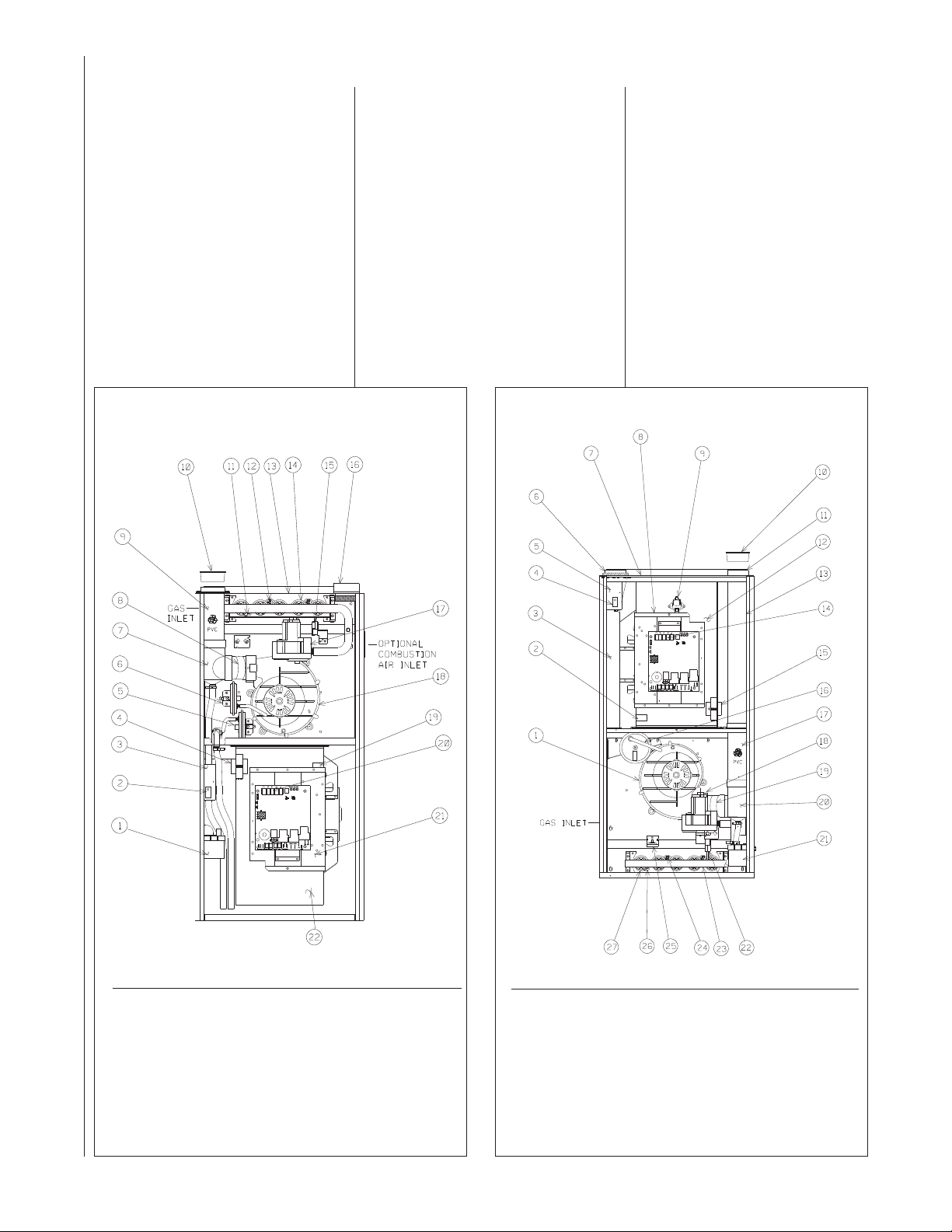
FIGURE 1
PFLOW FURNACE
U
FIGURE 2
OWNFLOW/HORIZONTAL FURNACE
D
ITEM ITEM
NO. PART NAME NO. PART NAME
1 CONDENSATE TRAP 13 TOP PLATE
2 DOOR SWITCH 14 BURNER
3 JUNCTION BOX 15 IGNITER (HSI ONLY)
4 TRANSFORMER 16 COMBUSTION AIR INLET
5 BLOCKED DRAIN PRESSURE SWITCH 17 GAS VALVE
6 MAIN PRESSURE SWITCH 18 INDUCED DRAFT BLOWER
7 EXHAUST TRANSITION 19 CAPACITOR
8 CONNECTOR 20 LOW VOLTAGE (THERMOSTAT)
9 OUTLET AIR PIPE TERMINAL
10 SHIPPING PLUG 21 CONTROL MOUNTING PLATE
11 FLAME SENSOR 22 BLOWER
12 OVERTEMPERATURE SWITCH
10
I409 I409
ITEM ITEM
NO. PART NAME NO. PART NAME
1 INDUCED DRAFT BLOWER 14 LOW VOLTAGE TERMINAL (THERMOSTAT)
2 CAPACITOR 15 TRANSFORMER
3 INLET AIR CHASE 16 PRESSURE SWITCH
4 DOOR SWITCH 17 OUTLET AIR PIPE
5 JUNCTION BOX 18 GAS VALVE
6 INLET PIPE CONNECTOR 19 CONNECTOR
7 TOP PLATE 20 EXHAUST TRANSITION
8 CONTROL MOUNTING PLATE 21 CONDENSATE TRAP
9 AUXILIARY LIMIT 22 IGNITER (HSI)
10 SHIPPING PLUG 23 MANIFOLD
11 EXHAUST CONNECTION 24 OVERTEMPERATURE SWITCH
12 BLOWER 25 ROLLOUT SWITCH
13 EXHAUST PIPE EXTENSION 26 FLAME SENSOR
27 BURNER
Page 11

IMPORTANT INFORMATION
ABOUT EFFICIENCY AND
INDOOR AIR QUALITY
Central cooling and heating equipment
is only as efficient as the duct system
that carries the cooled or heated air. To
maintain efficiency, comfort and good
indoor air quality, it is important to have
he proper balance between the air
t
being supplied to each room and the air
returning to the cooling and heating
equipment.
Proper balance and sealing of the duct
system improves the efficiency of the
heating and air conditioning system
and improves the indoor air quality of
the home by reducing the amount of
airborne pollutants that enter homes
from spaces where the ductwork and /
or equipment is located. The
manufacturer and the U.S.
Environmental Protection Agency’s
Energy Star Program recommend that
central duct systems be checked by a
qualified contractor for proper balance
and sealing.
WARNING
!
DUCT LEAKS CAN CREATE AN
UNBALANCED SYSTEM AND DRAW
POLLUTANTS SUCH AS DIRT,
DUST, FUMES AND ODORS INTO
THE HOME CAUSING PROPERTY
DAMAGE. FUMES AND ODORS
FROM TOXIC, VOLATILE OR
FLAMMABLE CHEMICALS, AS
WELL AS AUTOMOBILE EXHAUST
AND CARBON MONOXIDE (CO),
CAN BE DRAWN INTO THE LIVING
SPACE THROUGH LEAKING DUCTS
AND UNBALANCED DUCT
SYSTEMS CAUSING PERSONAL
INJURY OR DEATH (SEE FIGURE 3).
• IF AIR-MOVING EQUIPMENT OR
DUCTWORK IS LOCATED IN
GARAGES OR OFF-GARAGE
STORAGE AREAS - ALL JOINTS,
SEAMS, AND OPENINGS IN THE
EQUIPMENT AND DUCT MUST BE
SEALED TO LIMIT THE
MIGRATION OF TOXIC FUMES
AND ODORS INCLUDING CARBON
MONOXIDE FROM MIGRATING
INTO THE LIVING SPACE.
• IF AIR-MOVING EQUIPMENT OR
DUCTWORK IS LOCATED IN
SPACES CONTAINING FUEL
BURNING APPLIANCES SUCH AS
WATER HEATERS OR BOILERS ALL JOINTS, SEAMS, AND
OPENINGS IN THE EQUIPMENT
AND DUCT MUST ALSO BE
SEALED TO PREVENT
DEPRESSURIZATION OF THE
SPACE AND POSSIBLE
MIGRATION OF COMBUSTION
BYPRODUCTS INCLUDING
CARBON MONOXIDE INTO THE
LIVING SPACE.
FIGURE 3
IGRATION OF DANGEROUS SUBSTANCES, FUMES, AND ODORS INTO LIVING SPACES
M
NOTICE
IMPROPER INSTALLATION, OR
INSTALLATION NOT MADE IN
ACCORDANCE WITH THE CSA
INTERNATIONAL (CSA)
CERTIFICATION OR THESE
INSTRUCTIONS, CAN RESULT IN
UNSATISFACTORY OPERATION
AND/OR DANGEROUS CONDITIONS AND ARE NOT COVERED BY
THE UNIT WARRANTY.
NOTICE
IN COMPLIANCE WITH RECOGNIZED
CODES, IT IS RECOMMENDED THAT
AN AUXILIARY DRAIN PAN BE
INSTALLED UNDER ALL
EVAPORATOR COILS OR UNITS
CONTAINING EVAPORATOR COILS
OR GAS FURNACES USED WITH
EVAPORATOR COILS THAT ARE
LOCATED IN ANY AREA OF A
STRUCTURE WHERE DAMAGE TO
THE BUILDING OR BUILDING
CONTENTS MAY OCCUR AS A
RESULT OF AN OVERFLOW OF THE
COIL DRAIN PAN OR A STOPPAGE
IN THE PRIMARY CONDENSATE
DRAIN PIPING.
RECEIVING
Immediately upon receipt, all cartons
and contents should be inspected for
transit damage. Units with damaged
cartons should be opened immediately.
If damage is found, it should be noted
on the delivery papers, and a damage
claim filed with the last carrier.
• After unit has been delivered to job
site, remove carton taking care not to
damage unit.
• Check the unit rating plate for unit
size, electric heat, coil, voltage,
phase, etc. to be sure equipment
matches what is required for the job
specification.
• Read the entire instructions before
starting the installation.
• Some building codes require extra
cabinet insulation and gasketing
when unit is installed in attic
applications.
• If installed in an unconditioned
space, apply caulking around the
power wires, control wires,
refrigerant tubing and condensate
line where they enter the cabinet.
Seal the power wires on the inside
where they exit conduit opening.
Caulking is required to prevent air
leakage into and condensate from
forming inside the unit, control box,
and on electrical controls.
• Install the unit in such a way as to
allow necessary access to the
coil/filter rack and blower/control
compartment.
• Install the unit in a level position to
ensure proper condensate
drainage. Make sure unit is level in
both directions within 1/8”.
• Install the unit in accordance with
any local code which may apply
and the national codes. Latest
editions are available from:
“National Fire Protection
Association, Inc., Batterymarch
Park, Quincy, MA 02269.” These
publications are:
• ANSI/NFPA No. 70-(Latest Edition)
National Electrical Code.
• NFPA90A Installation of Air
Conditioning and Ventilating
Systems.
• NFPA90B Installation of warm air
heating and air conditioning
systems.
• The equipment has been
evaluated in accordance with the
Code of Federal Regulations,
Chapter XX, Part 3280.
11
Page 12
LOCATION REQUIREMENTS AND CONSIDERATIONS
GENERAL INFORMATION
WARNING
!
DO NOT USE THIS FURNACE
DURING CONSTRUCTION IF AIR
LADEN CORROSIVE COMPOUNDS
ARE PRESENT SUCH AS
CHLORINE AND FLUORINE.
OTHERWISE, PROVISIONS MUST
BE TAKEN TO PROVIDE CLEAN,
UNCONTAMINATED COMBUSTION
AND VENTILATION AIR TO THE
FURNACE. FURNACE
COMBUSTION AND VENTILATION
AIR CONTAMINATED WITH THESE
COMPOUNDS FORMS ACIDS
DURING COMBUSTION WHICH
CORRODES THE HEAT
EXCHANGER AND COMPONENT
PARTS. SOME OF THESE
CONTAMINANTS ARE FOUND IN,
BUT NOT LIMITED TO, PANELING,
DRY WALL, ADHESIVES, PAINTS,
STAINS, VARNISHES, SEALERS,
AND MASONRY CLEANING
MATERIALS.
WARNING
!
DO NOT INSTALL THIS FURNACE
IN A MOBILE HOME!! This furnace
is not approved for installation in a
mobile home. Doing so could cause
FIRE, PROPERTY DAMAGE,
PERSONAL INJURY OR DEATH.
WARNING
!
WHEN THIS FURNACE IS
INSTALLED IN A RESIDENTIAL
GARAGE, IT MUST BE INSTALLED
SO THE BURNERS AND IGNITION
SOURCE ARE LOCATED NO LESS
THAN 18 INCHES ABOVE THE
FLOOR. THIS IS TO PREVENT
THE RISK OF IGNITING
FLAMMABLE VAPORS WHICH
MAY BE PRESENT IN A GARAGE.
ALSO, THE FURNACE MUST BE
LOCATED OR PROTECTED TO
AVOID PHYSICAL DAMAGE BY
VEHICLES. FAILURE TO FOLLOW
THESE WARNINGS CAN CAUSE A
FIRE OR EXPLOSION, RESULTING
IN PROPERTY DAMAGE,
PERSONAL INJURY OR DEATH.
1. IMPORTANT: If installing the unit
over a finished ceiling or living
rea, be certain to install an
a
auxiliary condensate drain pan
under the entire unit. This
uxiliary drain pan should extend
a
under any evaporator coil
installed with the furnace and the
pen portion of the condensate
o
drain assembly. See
“Condensate Drain/Neutralizer”
section for more details.
2. IMPORTANT: If using a cooling
evaporator coil with this furnace:
a. be sure the air passes over
the heat exchanger before
passing over the cooling
coil. The cooled air passing
over the warm ambient air
inside the heat exchanger
tubes can cause
condensation inside the tubes
resulting in corrosion and
eventual failure.
b. install a parallel duct system
to divert all the air from the
furnace allowing it to pass
over the cooling coil only. Use
dampers or other means to
prevent chilled air from
passing over the heat
exchanger.
If these are manual dampers, they
must be equipped to prevent heating
or cooling operation unless the
damper is in the full heat or cool
position.
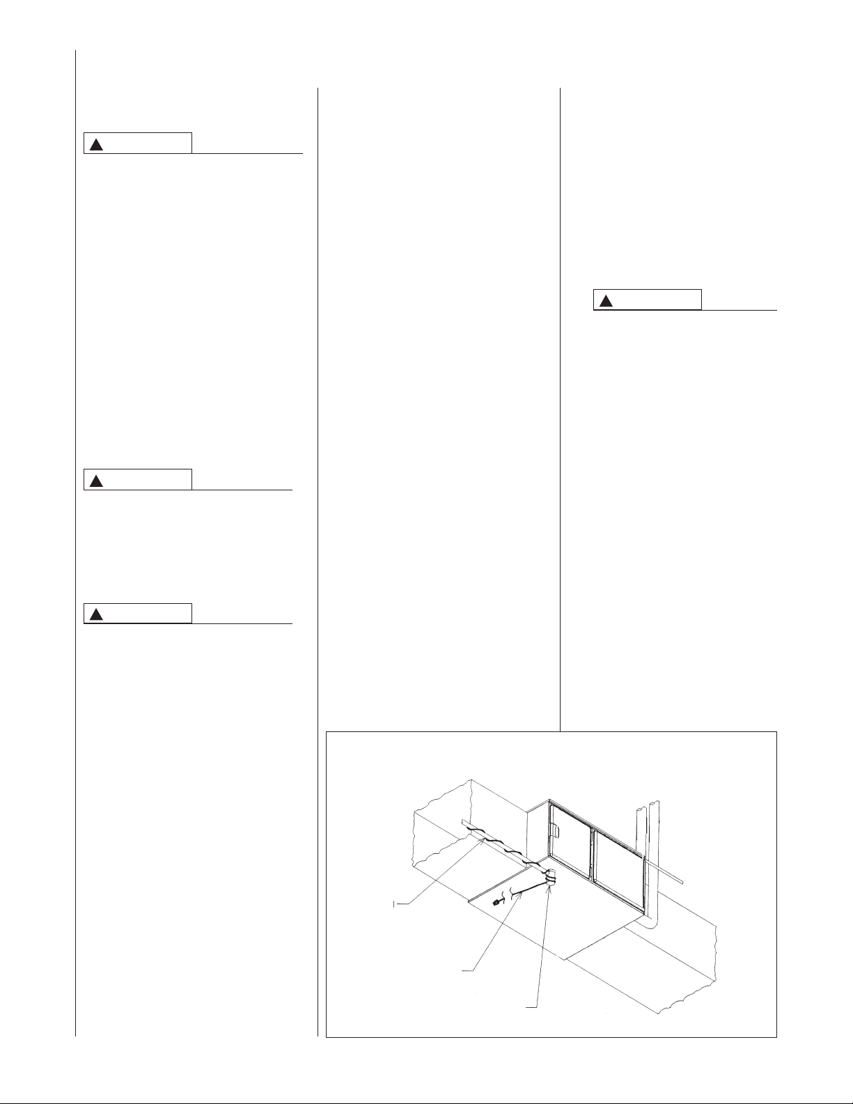
FIGURE 4
HORIZONTAL FURNACE W/HEAT TAPE ON CONDENSATE TRAP
DRAIN
PIPE
3. IMPORTANT: Install the furnace
level. If it is not level, condensate
annot drain properly, possibly
c
causing furnace shut down.
NOTE: These furnaces are approved
for installation in attics, as well as
alcoves, utility rooms, closets and
crawlspaces. Provisions must be
made to prevent freezing of
condensate.
4.
!
If this furnace is installed in a
garage, attic and/or any
unconditioned space, install a
self-regulating heat tape
around the condensate trap
and along the entire length of
the condensate drain in the
unconditioned space. See
Figure 4.
When the condensing horizontal
gas furnace is installed in an
unconditioned space where the
temperature would be capable of
reaching close to or below 32°F
(0°C). a self-regulating heat tape
is required on the condensate
drain, along with an insulation
wrap. The heat tape should meet
the following requirements:
a. The heat tape must be UL
b. The heat tape must be
CAUTION
listed.
installed per the
manufacturer’s instructions for
the entire length of drain pipe
in the unconditioned space.
12
HEAT
TAPE
TRAP
I526
Page 13
c. The heat tape should be rated
at 5 or 6 watts per foot at
20V.
1
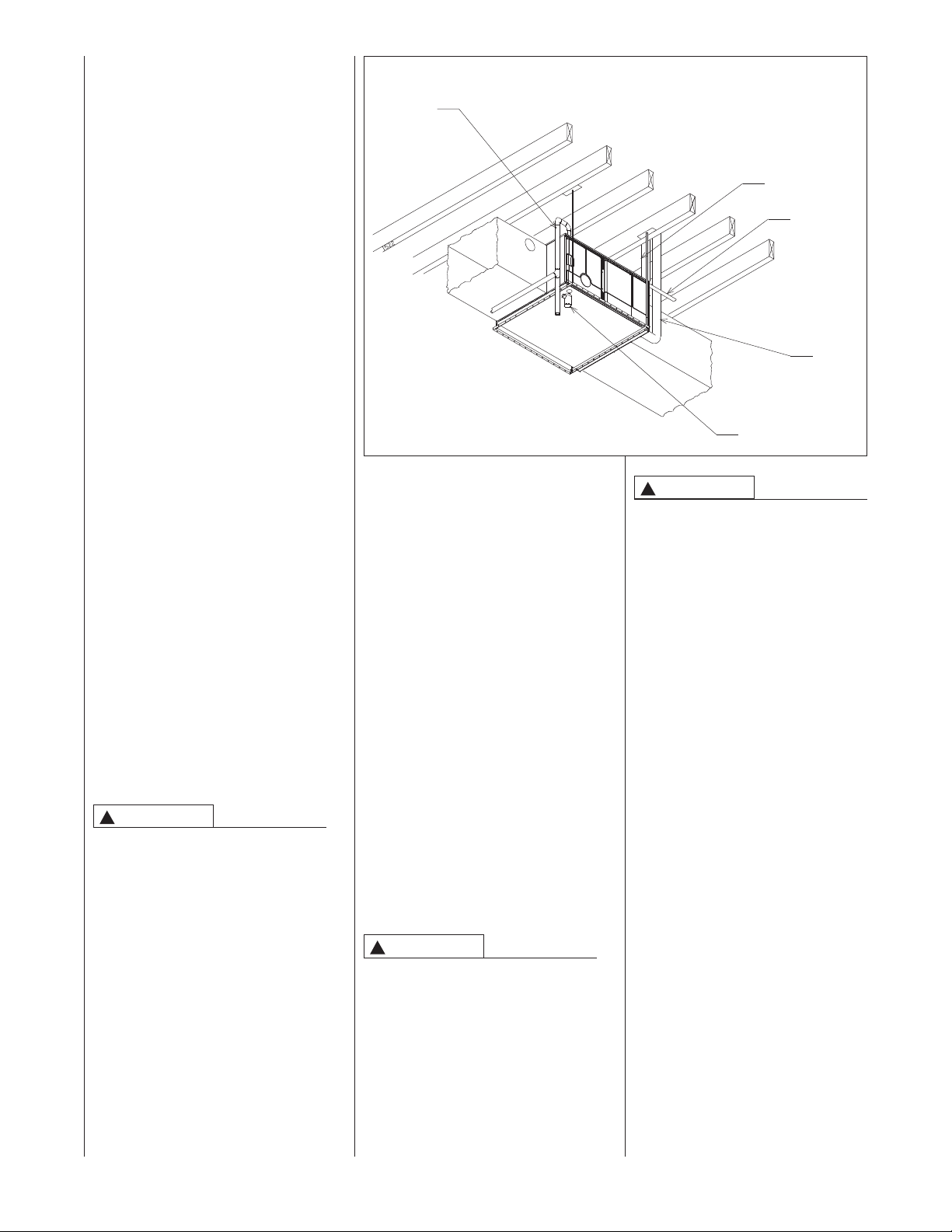
IMPORTANT: Support this unit
when installed. Since this furnace
is suitable for attic or crawl space
installation, it may be installed on
combustible wood flooring or by
using support brackets. See
Figure 5.
5. IMPORTANT: If installing in a
utility room, be sure the door
is wide enough to:
a. allow the largest part of the
furnace to pass; or
b. allow any other appliance
(such as a water heater)
to pass.
6. IMPORTANT: This furnace is not
approved or recommended for
installation on its back, with
access doors facing upwards.
IGURE 5
F
ORIZONTAL FURNACE INSTALLED W/SUPPORT BRACKETS
H
AS
G
IPE
P
T
RAP
NTAKE
I
ENT
V
ELECTRICAL
CONDUIT
XHAUST
E
AN
F
I522
CLEARANCE ACCESSIBILITY
The design of forced air furnaces with
input ratings as listed in the tables
under Figures 6, 7, and 8 are certified
by CSA-International for the
clearances to combustible materials
shown in inches.
See name/rating plate and clearance
label for specific model number and
clearance information.
Service clearance of at least 24
inches is recommended in front of
all furnaces.
NOTE: Use recommended 24”
clearance if accessibility clearances
are greater than fire protection
clearances.
WARNING
!
UPFLOW AND HORIZONTAL
FURNACES ARE DESIGNCERTIFIED FOR INSTALLATION
ON COMBUSTIBLE FLOORS.
NOTE, HOWEVER, THAT
FURNACES MUST NOT BE
INSTALLED DIRECTLY ON
CARPETING, TILE OR OTHER
COMBUSTIBLE MATERIAL OTHER
THAN WOOD FLOORING.
INSTALLATION ON A
COMBUSTIBLE MATERIAL CAN
RESULT IN FIRE, CAUSING
PROPERTY DAMAGE, PERSONAL
INJURY OR DEATH.
Upflow furnaces are shipped with a
bottom closure panel installed.
When bottom return air is used,
remove the panel by removing the
two screws attaching the panel to
the front base angle.
SITE SELECTION
1. Select a site in the building near
the center of the proposed, or
existing, duct system.
2. Give consideration to the vent
system piping when selecting the
furnace location. Be sure the
venting system can get from the
furnace to the termination with
minimal length and elbows.
3. Locate the furnace near the
existing gas piping. Or, if running
a new gas line, locate the
furnace to minimize the length
and elbows in the gas piping.
4. Locate the furnace to maintain
proper clearance to combustibles
as shown in the following tables.
WARNING
!
DO NOT LIFT THE UNIT BY THE
HEAT EXCHANGER TUBES.
DOING SO CAN CRACK THE HEAT
EXCHANGER ASSEMBLY AND
CAUSE CO2 TO BE RELEASED
INTO THE ENVIRONMENT, WHICH
CAN RESULT IN PERSONAL
INJURY OR DEATH.
WARNING
!
COMBUSTIBLE MATERIAL MUST
NOT BE PLACED ON OR AGAINST
THE FURNACE JACKET. THE
AREA AROUND THE FURNACE
MUST BE KEPT CLEAR AND FREE
OF ALL COMBUSTIBLE
MATERIALS INCLUDING
GASOLINE AND OTHER
FLAMMABLE VAPORS AND
LIQUIDS. PLACEMENT OF
COMBUSTIBLE MATERIALS ON,
AGAINST OR AROUND THE
FURNACE JACKET CAN CAUSE
AN EXPLOSION OR FIRE
RESULTING IN PROPERTY
DAMAGE, PERSONAL INJURY OR
DEATH. THE HOMEOWNER
SHOULD BE CAUTIONED THAT
THE FURNACE AREA MUST NOT
BE USED AS A BROOM CLOSET
OR FOR ANY OTHER STORAGE
PURPOSES.
13
Page 14
IGURE 6
F
LEARANCE TO COMBUSTIBLES, UPFLOW UNITS
C
WGTS
BACK TOP FRONT VENT
SIDE SIDE
LEFT RIGHT SHIP
⁄32 0 0 0 1 2* 0 111
⁄32 0 0 0 1 2* 0 117
⁄32 0 0 0 1 2* 0 123
⁄32 0 0 0 1 2* 0 123
25
⁄8 2 15 13
5
9
25
25
⁄2 17
1
⁄8 2 15 13
⁄8 2 15 13
⁄8 2 18
5
5
1
⁄32 0 0 0 1 2* 0 160
⁄32 0 0 0 1 2* 0 148
⁄32 0 0 0 1 2* 0 152
9
9
25
⁄2 17
⁄2 17
1
1
⁄8 2 18
⁄8 2 18
⁄8 2 22 20
1
1
5
2 DIA.
GAS CONNECTION
⁄32 15
⁄32 15
⁄32 15
⁄32 19
⁄32 19
⁄32 19
11
11
11
27
UPFLOW MODELS MINIMUM CLEARANCE (IN.)
⁄2 16
⁄2 16
⁄2 16
1
1
1
kBtu
INPUT
2 45 17
3 75 17
4 75 21 19
2.5 60 17
TONS A B C D E F
⁄32 22
27
27
11
⁄2 23
1
5 120 24
4.5 105 21 19
4 & 5 90 21 19
AIR
*A service clearance of at least 24 inches is recommended in front of all furnaces.
A - Narrow Cabinet
B - Wide Cabinet
AIRFLOW
⁄8
3
27
RETURN
2 DIA.
AIR
SUPPLY
GAS CONNECTION
⁄16
7
26
14
I392
Page 15

IGURE 7
F
LEARANCE TO COMBUSTIBLES, DOWNFLOW UNITS
C
WGTS
BACK TOP FRONT VENT
SIDE SIDE
LEFT RIGHT SHIP
⁄8 0 0 0 1 2* 0 111
⁄8 0 0 0 1 2* 0 117
⁄8 0 0 0 1 2* 0 123
⁄8 0 0 0 1 2* 0 123
⁄8 0 0 0 1 2* 0 148
⁄8 0 0 0 1 2* 0 152
7
7
7
3
⁄8 13
⁄8 13
⁄8 13
5
⁄8 2 16
5
⁄8 17
5
5
1
⁄8 2 16
⁄8 2 16
⁄16 2 20
5
5
3
⁄8 0 0 0 1 2* 0 160
3
3
7
⁄8 17
⁄8 17
⁄8 20
1
1
5
⁄8 2 23
⁄16 2 20
⁄16 2 20
5
3
3
⁄16
13
25
2 DIA.
ALT. GAS
CONNECTION
⁄8
3
4
⁄32 15
⁄32 15
⁄32 15
⁄32 19
⁄32 19
⁄32 19
11
11
11
DOWNFLOW MODELS MINIMUM CLEARANCE (IN.)
⁄2 16
1
A B C D E F
45 17
kBtu
INPUT
2
TONS
11
⁄2 16
⁄2 16
1
1
60 17
75 17
75 21 19
3
4
2.5
⁄32 22
11
11
11
⁄2 23
1
90 21 19
105 21 19
120 24
5
4.5
4 & 4.5
AIR
SUPPLY
*A service clearance of at least 24 inches is recommended in front of all furnaces.
NOTE: RXGY-H01 is required for left-hand alternate condensate drain.
AIRFLOW
AIR
RETURN
GAS CONNECTION
2 DIA.
NOTE: IN DOWNFLOW CONFIGURATION, OPTIONAL AIR CUTOUT IS NOT PERMITTED.
I393
15
Page 16

IGURE 8
F
LEARANCE TO COMBUSTIBLES, HORIZONTAL UNITS
C
WGTS
BACK TOP FRONT VENT
SIDE SIDE
LEFT RIGHT SHIP
⁄8 0 0 0 1 2* 0 111
⁄8 0 0 0 1 2* 0 117
⁄8 0 0 0 1 2* 0 123
⁄8 0 0 0 1 2* 0 123
⁄8 0 0 0 1 2* 0 148
⁄8 0 0 0 1 2* 0 152
7
7
7
3
⁄8 13
⁄8 13
⁄8 13
5
⁄8 2 16
5
⁄32 15
11
HORIZONTAL MODELS MINIMUM CLEARANCE (IN.)
⁄2 16
1
A B C D E F
⁄8 17
5
5
1
⁄8 2 16
⁄8 2 16
⁄16 2 20
5
5
3
⁄32 15
⁄32 15
⁄32 19
11
11
27
⁄2 16
⁄2 16
1
1
⁄8 0 0 0 1 2* 0 160
3
3
5
⁄8 17
⁄8 17
⁄8 20
1
1
5
⁄8 2 23
⁄16 2 20
⁄16 2 20
5
3
3
⁄32 19
⁄32 19
⁄32 22
27
27
11
⁄2 23
1
IMPORTANT: This furnace is not approved or recommended for
installation on its back, with access doors facing upwards.
45 17
60 17
75 17
75 21 19
90 21 19
105 21 19
kBtu
INPUT
2
3
4
2.5
TONS
120 24
5
4.5
4 & 4.5
GAS
2 DIA.
CONNECTION
*A service clearance of at least 24 inches is recommended in front of all furnaces.
⁄16
13
25
2 DIA.
ALT. GAS
CONNECTION
⁄8
3
4
16
I520
Page 17

DUCTING
JACKET
DRILL (2)
3/16" DIA.
HOLES
8.000
4.875
1.531
roper air flow is required for the
P
orrect operation of this furnace.
c
oo little air flow can cause erratic
T
peration and can damage the heat
o
xchanger. The duct system must
e
arry the correct amount of air for
c
eating and cooling if summer air
h
onditioning is used.
c
Size the ducts according to
acceptable industry standards and
methods. The total static pressure
drop of the air distribution system
should not exceed 0.5" w.c.
NOTE: Return air grilles and warm air
registers must not be obstructed
WARNING
!
NEVER ALLOW THE PRODUCTS
OF COMBUSTION FROM THE
FLUE TO ENTER THE RETURN AIR
DUCTWORK OR THE CIRCULATED
AIR SUPPLY. ALL RETURN
DUCTWORK MUST BE
ADEQUATELY SEALED AND
SECURED TO THE FURNACE
WITH SHEET METAL SCREWS;
AND JOINTS, TAPED. ALL OTHER
DUCT JOINTS MUST BE SECURED
WITH APPROVED CONNECTIONS
AND SEALED AIRTIGHT. WHEN
AN UPFLOW FURNACE IS
MOUNTED ON A PLATFORM WITH
RETURN THROUGH THE BOTTOM,
IT MUST BE SEALED AIRTIGHT
BETWEEN THE FURNACE AND
THE RETURN AIR PLENUM. THE
FLOOR OR PLATFORM MUST
PROVIDE SOUND PHYSICAL
SUPPORT OF THE FURNACE
WITHOUT SAGGING, CRACKS, OR
GAPS, AROUND THE BASE,
PROVIDING A SEAL BETWEEN
THE SUPPORT AND THE BASE.
FAILURE TO PREVENT
PRODUCTS OF COMBUSTION
FROM BEING CIRCULATED INTO
THE LIVING SPACE CAN CREATE
POTENTIALLY HAZARDOUS
CONDITIONS, INCLUDING
CARBON MONOXIDE POISONING
THAT COULD RESULT IN
PERSONAL INJURY OR DEATH.
DO NOT, UNDER ANY
CIRCUMSTANCES, CONNECT
RETURN OR SUPPLY DUCTWORK
TO OR FROM ANY OTHER HEAT
PRODUCING DEVICE SUCH AS A
FIREPLACE INSERT, STOVE, ETC.
DOING SO MAY RESULT IN FIRE,
CARBON MONOXIDE POISONING,
EXPLOSION, PERSONAL INJURY
OR PROPERTY DAMAGE.
IMPORTANT: Some high efficiency
filters have a greater than normal
resistance to air flow. This can
adversely affect furnace operation.
BE SURE TO CHECK AIR FLOW.
IMPORTANT: When using outside
air, design and adjust the system to
maintain a return air temperature
ABOVE 55° F during the heating
season.
UPFLOW UNITS
1. Position the unit to minimize long
runs of duct or runs of duct with
any turns and elbows.
m
2. Open the return air compartment.
WARNING
!
UPFLOW FURNACE: A SOLID
METAL BASE PLATE MUST BE
INSTALLED IN THE FURNACE
BOTTOM WHEN USING SIDE
RETURN. FAILURE TO INSTALL A
BASE PLATE COULD CAUSE THE
PRODUCTS OF COMBUSTION TO
CIRCULATE INTO THE LIVING
PACE AND CREATE POTENTIAL-
S
LY HAZARDOUS CONDITIONS,
INCLUDING CARBON MONOXIDE
POISONING OR DEATH.
a. Cut an opening in the side.
The opening should
be cut the full width of the
knockouts on the unit. See
Figure 9.
NOTE: Where the maximum air flow
is 1800 CFM or more, both sides or
the bottom must be used for return
air.
3. Connect the return duct or return
air cabinet to the unit. Make the
connection air tight to prevent
entraining combustion gases
from an adjacent fuel-burning
appliance.
4. Be sure to have adequate
space for the unit filter.
NOTE: DO NOT take return air
from bathrooms, kitchens,
furnace rooms, garages, utility or
laundry rooms, or cold areas.
NOTE: DO NOT use a rear air
return.
FIGURE 9
CUTOUT AND DRILL INFORMATION
5. If summer air conditioning is
desired, position the indoor coil
on the top of the unit. Insure that
no air can bypass this coil.
. Connect the supply air plenum to
6
the furnace plenum opening.
IMPORTANT: If a flexible duct
connector must be used, it
MUST
be rated for a minimum
temperature of 250°F
continuous.
.
DOWNFLOW UNITS
1. Position the unit to minimize long
uns of duct or runs of duct with
r
many turns and elbows.
2. If summer air conditioning is
desired, position the indoor coil
on the bottom of the unit. Insure
that no air can bypass this coil.
3. If installing on a combustible floor
and not using an air
conditioning plenum, install the
special non-combustible floor
base. See Figure 10.
WARNING
!
THE DOWNFLOW FURNACE
DESIGN IS CERTIFIED FOR
INSTALLATION ON A NONCOMBUSTIBLE FLOOR. USE THE
SPECIAL BASE SPECIFIED ON
THE FURNACE CLEARANCE
LABEL. FAILURE TO INSTALL THE
SPECIAL BASE MAY RESULT IN
FIRE, PROPERTY DAMAGE,
PERSONAL INJURY OR DEATH.
THIS SPECIAL BASE IS SHIPPED
FROM THE FACTORY AS AN
ACCESSORY.
17
Page 18

4. Connect the furnace to the
supply air plenum.
5. Connect the return air ducting to
the return air opening at the top
of the unit. Make the connection
air tight to prevent entraining
combustion gases from an
adjacent fuel-burning appliance.
6. Be sure to have adequate
space for the unit filter.
NOTE: DO NOT take return air
from bathrooms, kitchens,
furnace rooms, garages, utility or
laundry rooms, or cold areas.
HORIZONTAL UNIT
IMPORTANT: This furnace may only
be installed so as when facing the
front of the furnace, supply air is
discharged on the left hand side.
1. Position the unit to minimize long
runs or runs with many turns and
elbows.
2. If summer air conditioning is
desired, position the indoor coil
on the left end of the unit. Insure
that no air can bypass this coil.
3. Connect the furnace to the
supply air plenum.
4. Connect the return air ducting to
the return air opening at the right
end of the unit. Make the
connection air tight to prevent
pulling combustion gases from
an adjacent fuel-burning
appliance.
FIGURE 10
OMBUSTIBLE FLOOR BASE
C
5. Be sure to have adequate
space for the unit filter.
NOTE: DO NOT take return air
from bathrooms, kitchens,
furnace rooms, garages, utility or
laundry rooms, or cold areas.
VENTING AND COMBUSTION AIR PIPING
VENTING AND COMBUSTION AIR PIPING
GENERAL INFORMATION
WARNING
!
READ AND FOLLOW ALL
INSTRUCTIONS IN THIS SECTION.
FAILURE TO PROPERLY VENT
THIS FURNACE CAN CAUSE
CARBON MONOXIDE POISONING
OR AN EXPLOSION OR FIRE,
RESULTING IN PROPERTY
DAMAGE, PERSONAL INJURY
OR DEATH.
This furnace removes both sensible
and latent heat from the combustion
flue gases. Removal of latent heat
results in condensation of flue gas
water vapor. This condensed water
vapor drains from the secondary heat
exchanger and out of the unit into a
drain trap.
When installed as a non-direct vent
furnace, only exhaust piping is
required and inside combustion air
may be used. Refer to section on
“
COMBUSTION & VENTILATION AIR
FOR FURNACE INSTALLATIONS.”
Direct vent installations require a
dedicated combustion air and venting
system. All air for combustion is taken
from the outside atmosphere and all
combustion products are discharged
to the outdoors.
The combustion air and vent pipe
fittings must conform to American
National Standards Institute (ANSI)
and American Society for Testing
Materials (ASTM) standards as
shown below:
WARNING
!
IN CANADA, PRODUCTS
CERTIFIED FOR INSTALLATION
AND INTENDED TO BE VENTED
WITH PLASTIC VENT SYSTEMS
(PVC, CPVC) MUST USE VENT
SYSTEMS THAT ARE CERTIFIED
TO THE STANDARD FOR TYPE BH
GAS VENTING SYSTEMS, ULC
S636.
THE COMPONENTS OF THE
CERTIFIED MATERIAL MUST NOT
BE INTERCHANGED WITH OTHER
PIPE & FITTING MATERIAL
Schedule 40 PVC (Pipe) D1785
Schedule 40 PVC (Cellular Core Pipe) F891
Schedule 40 PVC (Fittings) D2466
SDR-21PVC (Pipe) D2241
SDR-26 PVC (Pipe) D2241
Schedule 40 ABS Cellular Core DWV (Pipe) F628
Schedule 40 ABS (Pipe) D1527
Schedule 40 ABS (Fittings) D2468
ABS-DWV (Drain Waste & Vent)
(Pipe & Fittings)
PVC-DWV (Drain Waste & Vent)
(Pipe & Fittings)
VENT SYSTEMS OR UNLISTED
PIPE/FITTINGS.
PLASTIC COMPONENTS AND
SPECIFIED PRIMERS AND GLUES
OF THE CERTIFIED SYSTEM MUST
BE FROM A SINGLE SYSTEM
MANUFACTURER AND NOT
INTERMIXED WITH OTHER
SYSTEM MANUFACTURER’S
PARTS.
NOTE: INLET AIR PIPING IS NOT
CONSIDERED TO BE A PART OF
THE “VENTING SYSTEM”. THE
REQUIREMENT THAT VENT
MATERIAL BE CERTIFIED TO ULC
S636 DOES NOT APPLY TO INLET
AIR PIPING.
ASTM
SPECIFICATION
D2661
D2665
18
Page 19

OVERTEMPERATURE
SAFETY SWITCHES
Furnaces are equipped with safety
switches in the control compartment to
protect against overtemperature
conditions caused by inadequate
combustion air supply. The switches for
the upflow and downflow models are
located in the burner compartment. If a
switch is tripped it must be manually
reset.
WARNING
!
DO NOT JUMPER THESE DEVICES!
IF ONE OF THESE SWITCHES
SHOULD TRIP, A QUALIFIED
INSTALLER, SERVICE AGENCY OR
THE GAS SUPPLIER MUST BE
CALLED TO CHECK AND/OR
CORRECT FOR ADEQUATE
COMBUSTION AIR SUPPLY. DO NOT
RESET THE SWITCHES WITHOUT
TAKING CORRECTIVE ACTION TO
ASSURE THAT AN ADEQUATE
SUPPLY OF COMBUSTION AIR IS
MAINTAINED UNDER ALL
CONDITIONS OF OPERATION.
FAILURE TO DO SO CAN RESULT IN
CARBON MONOXIDE POISONING
OR DEATH. IF THIS UNIT IS
MOUNTED IN A CLOSET, THE DOOR
MUST BE CLOSED WHEN MAKING
THIS CHECK.
REPLACE THESE SWITCHES ONLY
WITH THE IDENTICAL
REPLACEMENT PART.
EXISTING VENT SYSTEMS
When the installation of this furnace
replaces an existing furnace that is
removed from a vent system serving
other appliances, the vent system is
likely to be too large to properly vent the
remaining attached appliances.
The following steps should be followed
with each appliance remaining
connected to the original common vent
system. Place the appliance to be tested
in operation, while the other appliances
remaining connected to the common
vent system are not in operation. Test
the operation of each appliance
individually by the following method.
1. Permanently seal any unused
openings in the common venting
system.
2. Visually inspect the venting system
for proper size and horizontal pitch
and determine that there is no
blockage, restriction, leakage,
corrosion or other deficiencies
which could cause an unsafe
condition.
3. If practical, close all building doors,
windows and all doors between the
space where the appliances
remaining connected to the
common venting system are
located.
Turn on clothes dryers and any
appliance not connected to the
common venting system. Turn on
any exhaust fans, such as range
hoods and bathroom exhausts, so
they will operate at maximum
speed. Do not operate a summer
exhaust fan. Close fireplace
dampers.
4. Follow the lighting instructions.
Place the appliance being
inspected into operation. Adjust the
thermostat so the appliance will
operate continuously.
5. Test for spillage at the draft hood
relief opening after 5 minutes of
main burner operation. Use the
flame of a match or candle, or
smoke from a cigarette, cigar
or pipe.
6. After it has been determined that
each appliance that remains
connected to the common venting
system properly vents (when tested
as outlined above), return doors,
windows, exhaust fans, fireplace
dampers and any other gas-burning
appliance to their previous
conditions of use.
7. If improper venting is observed
during any of the above tests, the
common venting system must be
resized. See vent tables in these
instructions
When the furnace is installed in the
same space with other gas appliances
such as a water heater, be sure there is
an adequate supply of combustion and
ventilation air for the other appliances.
Do not delete or reduce the combustion
air supply required by the other gas
appliances in this space. See Z223.1,
National Fuel Gas Code (NFPA54) for
determining the combustion air
requirements for gas appliances. An
unconfined space must have at least 50
cubic feet (volume) for each
1,000 BTUH of the total input of all
appliances in the space. If the open
space containing the appliances is in a
building with tight construction
(contemporary construction), outside air
may still be required for the appliances
to burn and vent properly. Outside air
openings should be sized the same as
for a confined space.
JOINING PIPE AND
FITTINGS
WARNING
!
PVC SOLVENT CEMENTS AND
PRIMERS ARE HIGHLY FLAMMABLE.
PROVIDE ADEQUATE VENTILATION
AND DO NOT ASSEMBLE NEAR
HEAT SOURCE OR AN OPEN FLAME.
DO NOT SMOKE. AVOID SKIN OR
EYE CONTACT. OBSERVE ALL
CAUTIONS AND WARNINGS
PRINTED ON MATERIAL
CONTAINERS. FAILURE TO FOLLOW
THESE GUIDELINES MAY RESULT IN
FIRE, EXPLOSION OR
ASPHYXIATION CAUSING
PERSONAL INJURY OR DEATH.
All pipe, fittings, solvent cement, primers
and procedures must conform to
American National Standard Institute
and American Society for Testing and
Materials (ANSI/ASTM) standards in the
U.S.
Pipe and Fittings - ASTM-D1785,
D2466, D2665, D2231, D2661 and
F628.
PVC Primer and Solvent Cement ASTM-D2564
ABS Pipe and Fittings - Use ABS
Primer and Solvent Cement D2235
Procedure for Cementing Joints ASTM-D2855
IMPORTANT: The plastic combustion
air and venting components are of
PVC. If using ABS piping, ensure that
the solvent cement is compatible for
joining PVC to ABS components or
use a mechanical connection that can
withstand the vent temperatures and
are corrosion resistant.
CEMENTING JOINTS
Properly seal all joints in the PVC vent
using the following materials and
procedures.
PVC CLEANER-PRIMER AND
PVC MEDIUM-BODY SOLVENT
CEMENT
IMPORTANT: After cutting pipe,
remove all ragged edges and burrs.
This is important to prevent reduction
in pressure drop throughout the
system.
1. Cut pipe end square. Chamfer
edge of pipe. Clean fitting socket
and pipe joint area of all dirt,
grease and moisture.
2. After checking pipe and socket
for proper fit, wipe socket and
pipe with cleaner-primer. Apply
a liberal coat of primer to inside
surface of socket and outside of
pipe. Read instructions included
with the primer for proper
application.
3. Apply a thin coat of cement
evenly in the socket. Quickly
apply a heavy coat of cement to
the pipe end and insert pipe into
fitting with a slight twisting
movement until it bottoms out.
NOTE: Cement must be fluid; if
not, recoat.
4. Hold the pipe in the fitting for 30
seconds to prevent the tapered
socket from pushing the pipe out
of the fitting.
5. Wipe all excess cement from the
joint with a rag. Allow 15 minutes
before handling. Cure time varies
according to fit, temperature and
humidity.
NOTE: Stir the solvent cement
frequently while using. Use a natural
bristle brush or the dauber supplied
with the can. The proper brush size is
one inch.
IMPORTANT: For Proper Installation
DO NOT use solvent cement that
has become curdled, lumpy or
thickened.
DO NOT thin. Observe shelf
precautions printed on containers.
For application below 32°F, use only
low-temperature-type solvent
cement.
19
Page 20

COMBUSTION AND VENTILATION AIR
NON-DIRECT
Halogen type refrigerants
FURNACE INSTALLATIONS
WARNING
!
THE FURNACE AND ANY OTHER
UEL-BURNING APPLIANCE MUST
F
BE PROVIDED WITH ENOUGH
FRESH AIR FOR PROPER
COMBUSTION AND VENTILATION
OF THE FLUE GASES. MOST
HOMES WILL REQUIRE THAT
OUTSIDE AIR BE SUPPLIED INTO
THE FURNACE AREA. FAILURE
TO DO SO CAN CAUSE
PERSONAL INJURY OR DEATH
FROM CARBON MONOXIDE
POISONING.
Adequate facilities for providing air for
combustion and ventilation must be
provided in accordance with section
5.3, “Air for Combustion and
Ventilation” of the National Fuel Gas
Code, ANSI Z223.1 (latest edition) or
applicable provisions for the local
building codes, and not obstructed so
as to prevent the flow of air to the
furnace.
IMPORTANT: Air for combustion and
ventilation must not come from a
corrosive atmosphere. Any failure
due to corrosive elements in the
atmosphere is excluded from
warranty coverage.
The following types of installation
(but not limited to the following) will
require OUTDOOR AIR for
combustion, due to chemical
exposures:
• Commercial buildings
• Buildings with indoor pools
• Furnaces installed in laundry rooms
• Furnaces in hobby or craft rooms
• Furnaces installed near chemical
storage areas.
Exposure to the following substances
in the combustion air supply (but not
limited to the following) will also
require OUTDOOR AIR for
combustion:
• Permanent wave solutions
• Chlorinated waxes and cleaners
• Chlorine-based swimming pool
chemicals
• Water softening chemicals
• De-icing salts or chemicals
• Carbon tetrachloride
•
• Cleaning solvents (such as
perchloroethylene)
• Printing inks, paint removers,
varnishes, etc.
• Hydrochloric acid
Cements and glues
•
• Antistatic fabric softeners for
clothes dryers
• Masonry curing and acid washing
materials
Combustion air must be free of acidforming chemicals such as sulphur,
fluorine and chlorine. These elements
are found in aerosol sprays,
detergents, bleaches, cleaning
solvents, air fresheners, paint and
varnish removers, refrigerants and
many other commercial and
household products. When burned in
a gas flame, vapors from these
products form acid compounds. The
acid compounds increase the dew
point temperature of the flue products
and are highly corrosive after they
condense.
WARNING
!
ALL FURNACE INSTALLATIONS
MUST COMPLY WITH THE
NATIONAL FUEL GAS CODE AND
LOCAL CODES TO PROVIDE
ADEQUATE COMBUSTION AND
VENTILATION AIR FOR THE
FURNACE. FAILURE TO DO SO
CAN RESULT IN EXPLOSION,
FIRE, PROPERTY DAMAGE,
CARBON MONOXIDE POISONING,
PERSONAL INJURY OR DEATH.
Combustion air requirements are
determined by whether the furnace is
in an open (unconfined) area or in a
confined space such as a closet or
small room.
EXAMPLE 1:
FURNACE LOCATED IN AN
UNCONFINED SPACE
Using indoor air for combustion.
An unconfined space must have at
least 50 cubic feet for each 1,000
BTUH of the total input for all
appliances in the space. Here are a
few examples of the room sizes
required for different inputs. The sizes
are based on 8-foot ceilings.
TUH Minimum Sq. Feet Typical Room Size
B
Input With 8' Ceiling With 8' Ceiling
5,000 281 14' x 20' OR 16' x 18'
4
0,000 375 15' x 25' OR 19' x 20'
6
5,000 469 15' x 31' OR 20' x 24'
7
0,000 563 20’ x 28’ OR 24’ x 24’
9
105,000 657 20' x 33' OR 26' x 25'
120,000 750 25' x 30' OR 24' x 32'
If the open space containing the
furnace is in a building with tight
construction, outside air may still be
required for the furnace to operate
and vent properly. Outside air
openings should be sized the same
as for a confined space.
EXAMPLE 2:
FURNACE LOCATED IN A
CONFINED SPACE
A confined space (any space smaller
than shown above as “unconfined”)
must have openings into the space
which are located in accordance with
the requirements set forth in the
following subsections A and B. Size
the openings by how they are
connected to the heated area or to
the outside,
and by the input of all appliances in
the space.
If confined space is within a building
with tight construction, combustion air
must be taken from outdoors or area
freely communicating with the
outdoors.
A. USING INDOOR AIR FOR
COMBUSTION
IMPORTANT: Air should not be
taken from a heated space with a
fireplace, exhaust fan or other
device that may produce a
negative pressure.
If combustion air is taken from the
heated area, the openings must
each have at least 100 square
inches of free area. Each opening
must have at least one square inch
of free area for each 1,000 BTUH
of total input in the space. Here
are some examples of typical
openings required.
20
Page 21
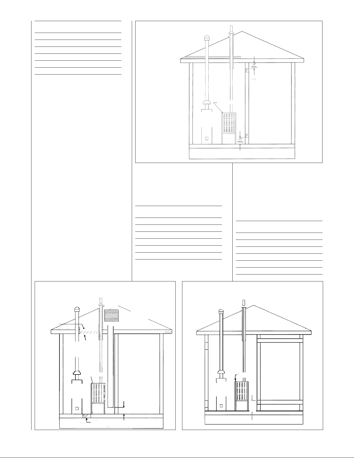
TUH Free Area
B
nput Each Opening
I
5,000 100 square inches
4
0,000 100 square inches
6
5,000 100 square inches
7
90,000 100 square inches
105,000 105 square inches
120,000 120 square inches
B. USING OUTDOOR AIR FOR
COMBUSTION
IMPORTANT: Do not take air from
an attic space that is equipped
with power ventilation.
The confined space must
communicate with the outdoors in
accordance with Methods 1 or 2.
The minimum dimension of air
openings shall not be less than 3
inches. Where ducts are used,
they shall be of the same crosssectional area as the free area of
the openings to which they
connect.
Method 1
Two permanent openings, one
located within 12 inches of the top
and one located within 12 inches
of the bottom of the enclosure,
shall be provided. The openings
shall communicate directly, or by
ducts, with the outdoors or spaces
(crawl or attic) that freely
communicate with the outdoors.
a. Where directly communicating
with the outdoors or where
communicating to the outdoors
IGURE 11
F
IR FROM HEATED SPACE
A
AS
G
WATER
HEATER
through vertical ducts as shown in
Figure 12, each opening shall
have a minimum free area of 1
square inch for each 4,000 BTUH
of total appliance input rating in the
enclosure.
BTUH Free Area Round Pipe
Input Each Opening Size
45,000 11.25 square inches 4"
60,000 15.00 square inches 5"
75,000 18.75 square inches 5"
90,000 22.50 square inches 6"
105,000 26.25 square inches 6"
120,000 30.00 square inches 6"
FURNACE
NOTE:
ACH OPENING SHALL
E
HAVE A FREE AREA OF
NOT LESS THAN ONE
QUARE INCH PER 1,000
S
BTU PER HOUR OF THE
TOTAL INPUT RATING OF
LL EQUIPMENT IN THE
A
ENCLOSURE, BUT NOT
LESS THAN 100 SQUARE
NCHES.
I
b. Where communicating with
outdoors through horizontal ducts,
each opening shall have a
minimum free area of 1 square
inch for each 2,000 BTUH of total
input rating of all equipment in the
enclosure (See Figure 13).
Here are some typical sizes:
BTUH Free Area Round Pipe
Input Each Opening Size
45,000 22.50 square inches 6"
60,000 30.00 square inches 6"
75,000 37.50 square inches 7"
90,000 45.00 square inches 8"
105,000 52.50 square inches 8"
120,000 60.00 square inches 9"
FIGURE 12
AIR FROM ATTIC/CRAWL SPACE
OUTLET AIR
IN ATTIC
MUST BE
ABOVE
INSULATION
1 SQ. INCH PER
4000 BTUH
OUTLET AIR
FURNACE
GAS
WATER
HEATER
1 SQ. INCH PER
4000 BTUH INLET AIR
GABLE
VENT
OPTIONAL 1 SQ. INCH PER 4000 BTUH INLET AIR
VENTILATED
ATTIC GABLE OR
SOFFIT VENTS
12" MAX.
FIGURE 13
OUTSIDE AIR USING A HORIZONTAL DUCT
OUTLET AIR 1 SQ. INCH
FURNACE
GAS
WATER
HEATER
INLET AIR 1 SQ. INCH
12"
MAX.
PER 2000 BTUH
PER 2000 BTUH
21
Page 22
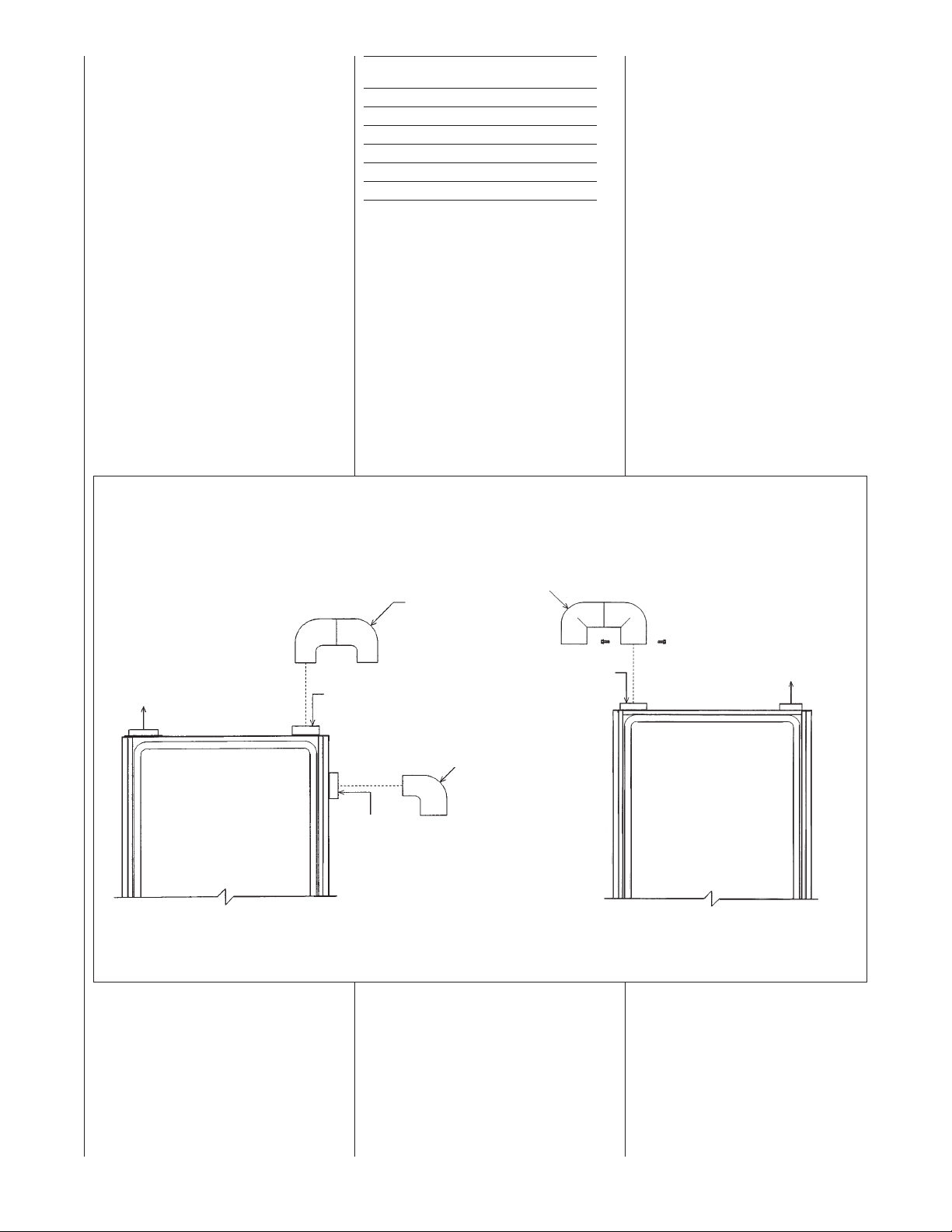
Method 2
(Not Shown)
One permanent opening, located
within 12 inches of the top of the
nclosure, shall be permitted
e
here the equipment has
w
clearances of at least 1 inch from
the sides and back and 6 inches
from the front of the appliance.
The opening shall directly
communicate with the outdoors or
communicate through a vertical or
horizontal duct to the outdoors or
spaces (crawl or attic) that freely
ommunicate with the outdoors,
c
and shall have a minimum free
area of:
a. 1 square inch for each 3,000
BTUH of the total input rating of
all equipment located in the
enclosure and
FIGURE 14
OMBUSTION AIR FITTING
C
TUH Free Area Round Pipe
B
nput Each Opening Size
I
5,000 15.00 square inches 4"
4
0,000 16.67 square inches 5"
6
5,000 25.00 square inches 6"
7
90,000 30.00 square inches 6"
105,000 35.00 square inches 7"
120,000 40.00 square inches 7"
b. Not less than the sum of the
areas of all vent connectors in
the confined space.
f unit is installed where there is an
I
exhaust fan, sufficient ventilation
must be provided to prevent the
exhaust fan from creating a negative
pressure.
Combustion air openings must not be
restricted in any manner.
CONSULT LOCAL CODES FOR
SPECIAL REQUIREMENTS.
CONNECTION TO
FURNACE
IMPORTANT: When indoor
ombustion air is used, the inlet air
c
opening at the furnace must be
protected from accidental blockage.
On upflow models, install a 90° elbow
pointing downward in the side inlet air
opening or a double elbow pointing
downward in the top inlet air opening.
On downflow/horizontal models,
install a double elbow in the top inlet
ir opening. See Figure 14.
a
UPFLOW DOWNFLOW/HORIZONTAL
ATTACH DOUBLE ELBOW TO TOP INLET
AIR OPENING OR 90° ELBOW TO SIDE
NLET AIR OPENING TO PREVENT
I
ACCIDENTAL BLOCKAGE OF INTAKE
OPENING. PLUG OPENING NOT USED.
EXHAUST
" PVC
2
DOUBLE
" PVC
2
DOUBLE
ELBOW
TOP
OPTION
2" PVC ELBOW
SIDE
OPTION
I337 I336
ELBOW*
COMBUSTION AIR
*NOTE: WHEN FURNACE IS INSTALLED IN A
HORIZONTAL POSITION ONLY ONE 90°
ELBOW IS REQUIRED. INSTALL THE ELBOW
SO THE OPEN END IS POINTED DOWNWARD.
TTACH DOUBLE ELBOW TO INTAKE AIR
A
COLLAR AND SECURE WITH TWO SHEET
METAL SCREWS TO PREVENT ACCIDENTAL
LOCKAGE OF INTAKE AIR OPENING.
B
EXHAUST
22
Page 23
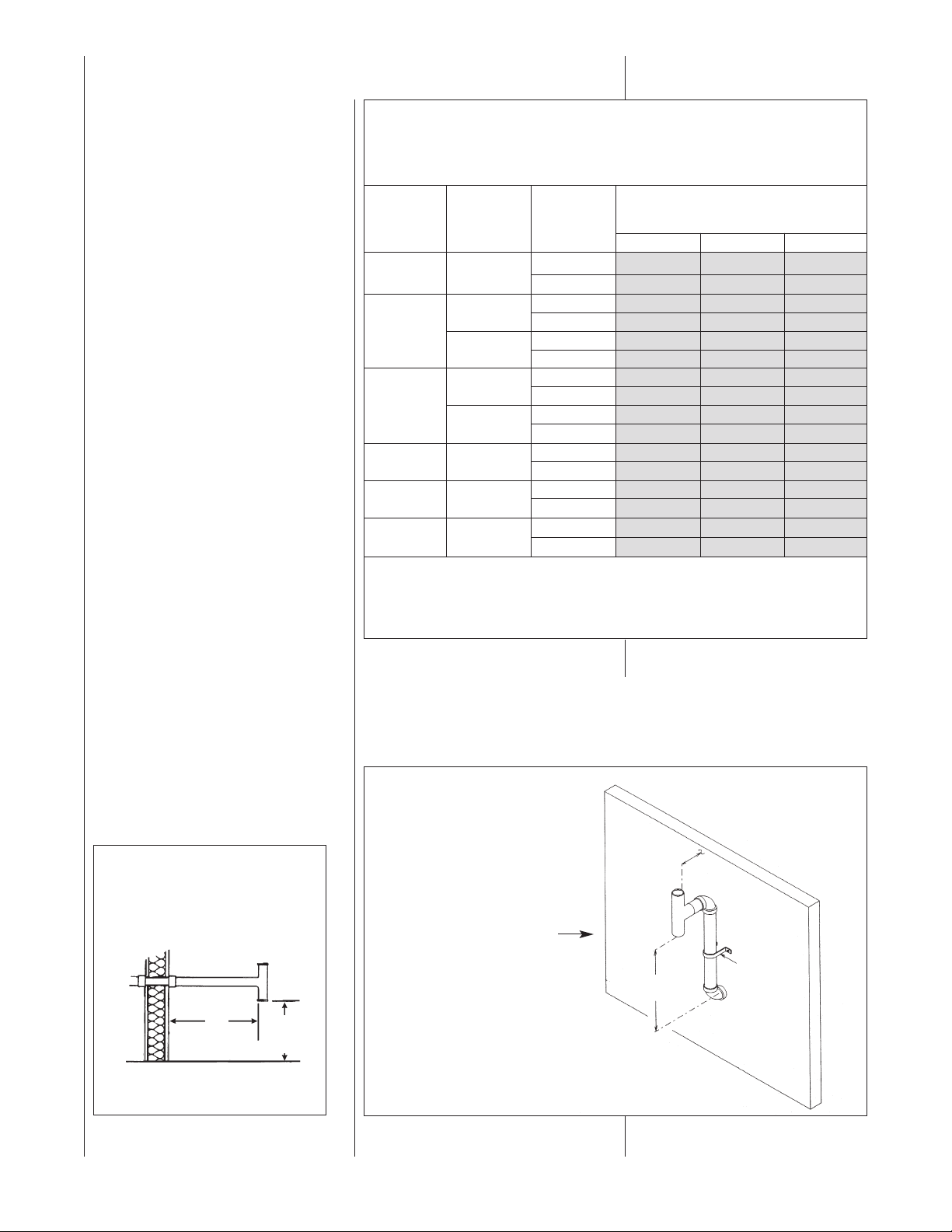
VENT PIPE INSTALLATION
NON-DIRECT VENT
INSTALLATION
GUIDELINES
IMPORTANT: Failure to correctly
follow all venting guidelines may
esult in erratic furnace operation,
r
freeze-up of combustion air or
exhaust air piping or sooting of the
furnace.
All exhaust piping must be installed in
compliance with Part 7, “Venting of
Equipment,” of the latest edition of the
National Fuel Gas Code NPFA54/
ANSI Z223.1-, local codes or
ordinances and these instructions.
1. Vertical piping is preferred.
2. All horizontal piping must slope
upward a minimum of
per foot of run so that
condensate drains toward the
furnace.
3. All horizontal runs must be
supported at least every 4 feet.
No sags or dips are permitted.
4. IMPORTANT: Do not common
vent with any other appliance. Do
not install in the same chase or
chimney with a metal or high
temperature plastic pipe from
another gas or fuel-burning
appliance unless the required
minimum clearances to
combustibles are maintained
between the PVC pipe and other
pipes.
5. All vent runs through
unconditioned spaces where
below-freezing temperatures are
expected should be insulated
with 1-in. thick, medium-density,
foil-faced fiberglass. An
equivalent “arm-a-flex” or
1
/4 inch
TABLE 1
OR NON-DIRECT VENT APPLICATIONS - AIR FOR COMBUSTION
F
ROVIDED FROM INDOORS
P
MAXIMUM ALLOWABLE LENGTH IN FEET OF EACH EXHAUST PIPE AND INTAKE PIPE
NUMBERS OF ELBOWS
FURNACE
INPUT
5,000 2”
4
60,000
5,000
7
0,000 3”
9
105,000 3”
120,000 3”
NOTES:
. *N.R. - NOT RECOMMENDED.
1
2. MAXIMUM OF 6 - 90 DEGREE ELBOWS MAY BE USED. DO NOT COUNT ELBOWS REQUIRED FOR
ALTERNATE TERMINATION. USE ONLY MEDIUM OR LONG SWEEP ELBOWS.
1
3. A 22
⁄2° or 45° DEGREE ELBOW IS CONSIDERED ONE ELBOW.
PIPE
SIZE
2
3”
2
3”
ERMINATION
T
1-2 3-4 5-6
Standard 60 55 50
Alternate 55 50 45
”
”
Standard 35 30 25
Alternate 30 25 20
tandard 120 120 115
S
lternate 120 120 110
A
tandard 30 25 NR
S
Alternate NR NR NR
Standard 110 105 95
Alternate 80 70 65
Standard 90 85 75
lternate 60 50 45
A
tandard 80 75 65
S
lternate 50 40 35
A
Standard 70 65 55
Alternate 40 30 25
45° OR 90°
Medium / Long Radius ONLY
ELEVATED SINGLE PIPE ALTERNATE TEE TERMINATION
See Figure 16. The tee termination may be elevated up to 24 inches above the
wall penetration if required for anticipated snow levels. Use 2 medium-radius, 2-in.
PVC elbows and 2-in. PVC pipe, attaching the tee so it is 12 inches from the wall.
FIGURE 16
ALTERNATE HORIZONTAL TERMINATION
FOR NON-DIRECT VENT
INSTALLATIONS
FIGURE 15
TEE TERMINAL – FOR STANDARD
HORIZONTAL SINGLE PIPE
INSTALLATION
VENT
12"
12" MIN.ABOVE
GRADE OR
SNOW LEVEL
OUTSIDE
WALL
24"
MAX.
12"
ROM
F
PIPE
SUPPORT
STRAP
I198
23
Page 24

“rub-a-tex” insulation may also be
used as long as there is no heat
tape applied to the vent pipe. For
horizontal runs where water may
collect, wrap the vent pipe with
self-regulating 3 or 5 watt heat
tape. The heat tape must be
U.L. listed and installed per the
manufacturer’s instructions.
6. The minimum vent pipe length is
5 feet.
STANDARD INSTALLATIONS
The single-pipe system requires an
exhaust pipe only. Combustion air may
be taken from the furnace installation
area or ducted to the furnace area from
the outside.
Size the exhaust pipe as specified in
Table 1. This table lists the maximum
allowable length in feet of the exhaust
pipe that may be used for all furnace
inputs as related to the number of
elbows required and the termination.
(See shaded area.)
Vertical through-the-roof installations do
not require a vent termination. Use 2-in.
PVC pipe extending a minimum of 12
inches above the anticipated level of
snow accumulation. See exhaust pipe
requirements, Figure 19. When 3-in.
vent pipe is used from furnace to the
roof, reduce it to 2 inches before
penetrating the roof. A maximum of 18
inches of 2-in. pipe may be used below
the roof. Maximum exposed vent length
above the roof line is 30ⴖ.
Horizontal vent terminations require a
2-in. PVC tee positioned 12 inches from
the outside wall. See exhaust pipe
requirements, Figure 22. When 3-in.
pipe is used from the furnace to the
outside wall, reduce it to 2 inches
before penetrating the wall. A maximum
of 18 inches of 2-in. pipe may be used
inside the wall.
An alternate termination may be used
as shown in Figure 16 to clear
anticipated snow levels. The tee may
be raised up to 24 inches above the
wall penetration. Use two mediumradius bend, 2-in. PVC elbows and a
length of 2-in. PVC pipe so that the
elbows are on 24-in. centers.
NSTALLATION CAN CAUSE
I
STRUCTURAL OR EXTERIOR
FINISH DAMAGE TO THE
BUILDING.
Non-direct venting location
equirements are slightly different in
r
some cases than direct venting. Install
a non-direct vent with the following
minimum clearances.
See Figure 17.
. Locate the bottom of the vent
1
terminal at least 12 inches above
grade. Increase the 12-in.
minimum to keep the terminal
openings above the level of snow
accumulation, where applicable.
2. The vent shall not terminate over
public walkways or over an area
where condensate or vapor could
create a nuisance or hazard.
3. 4 feet below, 4 feet horizontally
from, or 1 foot above any door,
window soffit, under eave vent or
gravity air inlet to the building.
4. The vent terminal shall have a
minimum horizontal clearance of
4 feet from electric meters, gas
meters, regulators and relief
equipment.
5. 6 feet from an inside corner
formed by two exterior walls –
10 feet is the recommended
distance.
6. Locate it 3 feet above any forced
air inlet located within 10 feet.
Any fresh air or make-up air inlet,
such as for a dryer or furnace
area, is considered a forced air
inlet.
7. Avoid areas where dripping
condensate may cause problems,
such as above planters, patios, or
adjacent to windows where
steam may cause fogging.
In addition to the minimum clearances
isted above, the vent location should
l
also be governed by the following
guidelines.
1. Do not terminate under any kind
of patio or deck. If running the
ent under a deck, insulate it to
v
insure no condensate freezes
and blocks the pipe.
2. Do not locate on the side of a
building with prevailing winter
inds. This will help prevent
w
moisture from freezing on walls
and overhangs (under eaves).
3. Do not extend vent directly
through brick or masonry
surfaces. Use a rust-resistant
sheet metal or plastic backing
plate behind vent.
4. Do not locate too close to shrubs
as condensate may stunt or kill
them.
5. Minimum vertical clearances of 1
foot are recommended for
overhangs up to 1 foot horizontal.
The vertical clearance should be
increased equally for each
additional increase in horizontal
overhang to a maximum vertical
clearance of 6 feet.
6. Caulk all cracks, seams and
joints within 6 feet horizontally
and above and below vent.
NON-DIRECT VENT TERMINATION
LOCATION REQUIREMENTS
CAUTION
!
MOISTURE IN THE COMBUSTION
PRODUCTS CONDENSES AS IT
LEAVES THE TERMINATION. THIS
CONDENSATE CAN FREEZE ON
EXTERIOR WALLS, UNDER THE
EAVES, AND ON SURROUNDING
OBJECTS. SOME DISCOLORATION
IS TO BE EXPECTED. HOWEVER,
IMPROPER LOCATION OR
24
Page 25
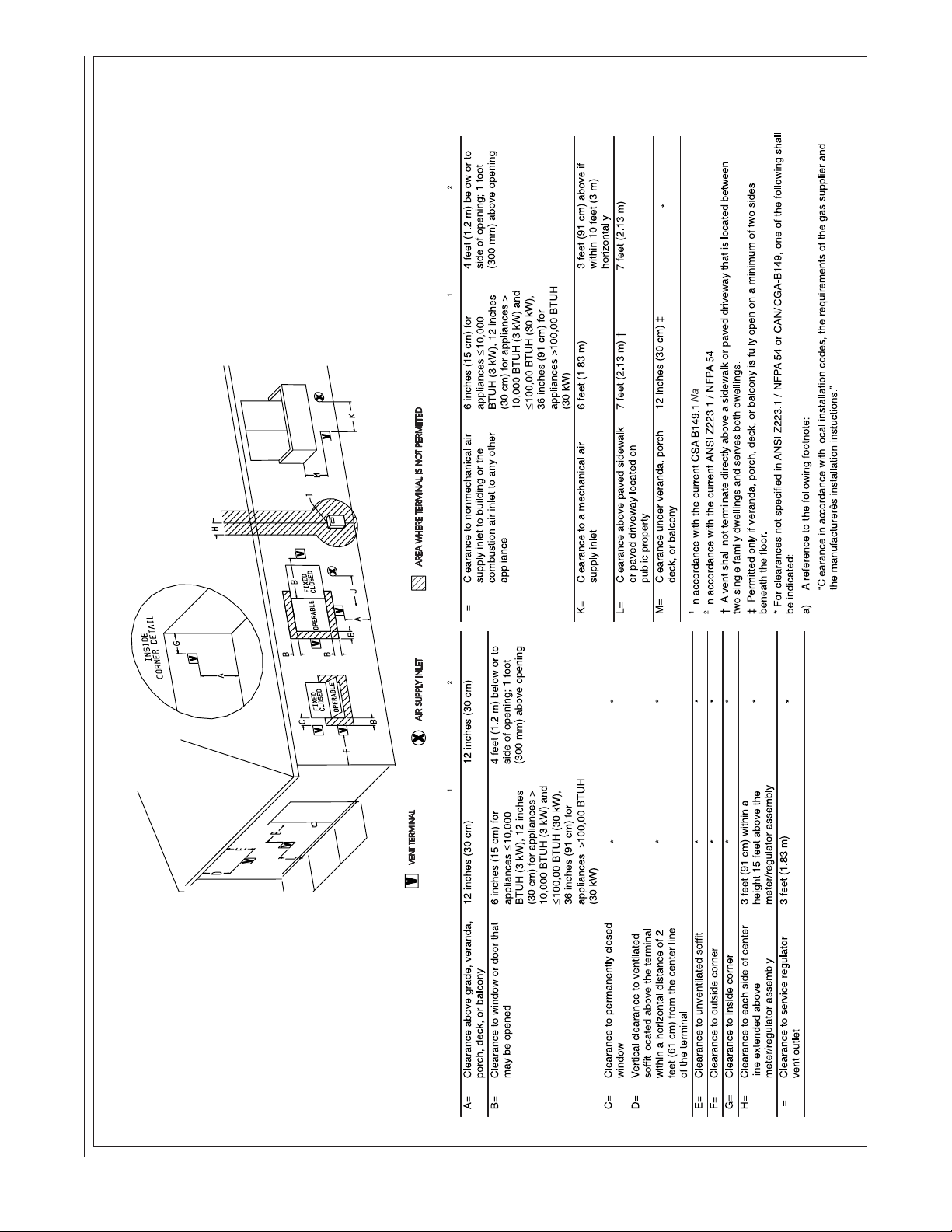
IGURE 17
Natural Gas and Propane Installation Code
National Fuel Gas Code
Canadian Installations
US Installations
Canadian Installations
US Installations
F
OTHER THAN DIRECT VENT TERMINAL CLEARANCES
25
Page 26

DIRECT VENT
INSTALLATIONS
WARNING
!
READ AND FOLLOW ALL
INSTRUCTIONS IN THIS SECTION.
FAILURE TO PROPERLY VENT
HIS FURNACE CAN CAUSE
T
CARBON MONOXIDE POISONING
OR AN EXPLOSION OR FIRE,
RESULTING IN PROPERTY
DAMAGE, PERSONAL INJURY
OR DEATH.
Direct vent installations require a
dedicated combustion air and venting
ystem. All air for combustion is taken
s
from the outside atmosphere and all
combustion products are discharged
to the outdoors. Therefore, no
ventilation or combustion air
openings are required.
IMPORTANT: The plastic combustion
air and venting components are of
Schedule 40 PVC. If using ABS
piping ensure that the solvent cement
is compatible for joining PVC to ABS
components or use a mechanical
connection that can withstand the
vent temperatures and are corrosion
resistant.
INSTALLATION GUIDELINES
All exhaust piping must be installed in
compliance with Part 7, “Venting of
Equipment,” of the latest edition of the
National Fuel Gas Code NPFA54/
ANSI Z223.1-, local codes or
ordinances and these instructions.
1. Vertical piping is preferred.
2. All horizontal piping must slope
upward a minimum of
per foot of run so that condensate
drains toward the furnace.
3. All horizontal runs must be
supported at least every 4 feet.
No sags or dips are permitted.
4. IMPORTANT: Do not common
vent with any other appliance. Do
not install in the same chase or
chimney with a metal or high
temperature plastic pipe from
another gas or fuel-burning
appliance unless the required
minimum clearances to
combustibles are maintained
between the PVC pipe and other
pipes.
1
/4 inch
TABLE 2
OR DIRECT VENT APPLICATIONS - AIR FOR COMBUSTION PROVIDED FROM OUTDOORS
F
MAXIMUM ALLOWABLE LENGTH IN FEET OF EACH EXHAUST PIPE AND INTAKE AIR PIPE
ENT TERMINATION
URNACE
F
NPUT
I
45,000 2”
6
7
9
05,000 3”
1
20,000 3” Alternate RXGY-D03/RXGY-D03A 45 35 30
1
NOTES:
PIPE
S
0,000
75-E*B) Alternate Not Recommended NR NR NR
(
(75-E*C) Alternate Not Recommended NR NR NR
5,000
0,000 3”
1.N.R. - NOT RECOMMENDED.
2.MAXIMUM OF 6 ELBOWS MAY BE USED. DO NOT COUNT ELBOWS IN ALTERNATE TERMINATION KIT.
MEDIUM OR LONG SWEEP ELBOWS MAY BE USED.
3.A 45 DEGREE ELBOW IS CONSIDERED ONE ELBOW.
.CONCENTRIC TERMINATION NO. RXGY-E03/RXGY-E03A IS FOR THRU-THE-ROOF OR THRU-THE-WALL
4
VENTING.
5.USE KITS RXGY-DO2/D02A (2"), RXGY-G02 (2"), OR RXGY-D03/D03A (3") FOR STANDARD OR ALTERNATE
THRU-THE-WALL VENTING.
6.USE KITS RXGY-D04/D04A FOR ALTERNATE VENTING OF 120,000 BTUH UNITS WITH LONG RUNS.
7.KIT NUMBERS CONTAINING SUFFIX “A” ARE APPROVED FOR INSTALLATION IN CANADA.
8.NO SCREENS MAY BE USED TO COVER COMBUSTION AIR AND EXHAUST.
ERMINATION
T
IZE
tandard/Concentric RXGY-D02/RXGY-D02A/RXGY-E03A/RXGY-G02 65 60 55
S
lternate RXGY-D02/RXGY-D02A 55 50 45
A
Standard/Concentric RXGY-D02/RXGY-D02A/RXGY-E03A/RXGY-G02 40 35 30
”
2
”
3
“ Standard/Concentric RXGY-D02/RXGY-D02A/RXGY-E03A 20 15 NR
2
“ Standard/Concentric RXGY-D02/RXGY-D02A/RXGY-E03A 30 25 NR
2
”
3
Alternate RXGY-D02/RXGY-D02A 30 25 20
Standard/Concentric RXGY-D03/RXGY-D03A/RXGY-E03A/RXGY-G02 120 120 120
Alternate RXGY-D03/RXGY-D03A 110 105 100
Standard/Concentric RXGY-D03/RXGY-D03A/RXGY-E03A 120 120 120
Alternate RXGY-D03/RXGY-D03A 100 95 85
Standard/Concentric RXGY-D03/RXGY-D03A/RXGY-E03A/RXGY-G02 110 105 95
Alternate RXGY-D03/RXGY-D03A 50 40 35
Standard/Concentric RXGY-D03/RXGY-D03A/RXGY-E03A/RXGY-G02 110 105 95
Alternate RXGY-D03/RXGY-D03A 50 40 35
tandard/Concentric RXGY-D03/RXGY-D03A/RXGY-E03A/RXGY-G02 45 35 30
S
Alternate RXGY-D04/RXGY-D04A 105 95 90
V
IT RECOMMENDED
K
RXGY-D0* Kits for
(
orizontal Venting Only)
H
NUMBER OF ELBOWS
45 or 90 Degrees
Medium / Long Radius ONLY
1 - 2 3 - 4 5 - 6
5. For horizontal runs where water
may collect, wrap the vent pipe
with self-regulating 3 or 5 watt
heat tape. The heat tape must be
U.L. listed and installed per the
manufacturer’s instructions.
6. The minimum vent pipe length is
5 feet.
Size the exhaust and combustion air
intake pipes as specified in Table 2.
This table lists the maximum allowable length in feet of the exhaust and
combustion air intake pipes that may
be used for all furnace inputs as
related to the number of elbows
required and the termination (see
shaded area).
7. The maximum exposed vent
length (above the roof line) is
30ⴖ.
26
Page 27

COMBUSTION AIR FOR
IRECT VENT
D
INSTALLATIONS
THE COMBUSTION AIR SYSTEM
DESIGNED FOR THIS FURNACE
MUST BE USED.
hen this furnace is installed as a
W
direct vent forced air furnace, all
combustion air is supplied directly to
the burner through a special air inlet
ystem outlined in these instructions.
s
This system consists of field-supplied
Schedule 40 or 26 SDR-PVC pipe
nd one of the following horizontal
a
vent termination kits: RXGY-D02 or
D02A, RXGY-D03 or D03A, RXGYD04 orD04A, or RXGY-E03A.
NOTE: Schedule 40 ABS-DWV pipe
and fittings may be used as an
alternate to PVC pipe for the
combustion air inlet and vent pipes.
The combustion air for this furnace is
supplied directly from the outdoors
through the combustion air inlet
system.
When the furnace is installed in the
same space with other gas
appliances, such as a water heater,
be sure there is an adequate supply
of combustion and ventilation air for
the other appliances. Do not delete or
reduce the combustion air supply
required by the other gas appliances
in this space. See Z223.1, National
Fuel Gas Code (NFPA54) for determining the combustion air
requirements for gas appliances. An
unconfined space must have at least
50 cubic feet (volume) for each
1,000 BTUH of the total input of all
appliances in the space. If the open
space containing the appliances is in
a building with tight construction
(contemporary construction), outside
air may still be required for the
appliances to burn and vent properly.
Outside air openings should be sized
the same as for a confined space.
STANDARD TERMINATIONS
STANDARD VERTICAL
TERMINATIONS
COMBUSTION AIR PIPING
Use two medium-radius sweep
elbows to keep the inlet downward to
prevent entry of rain. See Figure 22
for the proper relationship of
combustion air to exhaust
termination.
STANDARD HORIZONTAL
TERMINATIONS
OMBUSTION AIR PIPING
C
When 3-in. pipe is used between the
furnace and outside wall, reduce it
to 2 inches before penetrating the
wall. Up to 18 inches of 2-in. pipe
may be used inside the wall.
The standard horizontal intake air
termination for all models is a 2-in.
PVC coupling with a wind deflector
ane (provided) attached. Cut a
v
1
2
/4-in. length of 2-in. PVC pipe.
Connect this pipe and another 2-in.
PVC coupling to the coupling at the
all. The outer coupling must
w
terminate 4 inches from the wall. See
Figure 23, Detail B, for vane location.
Attach vane in vertical position with
PVC solvent.
IMPORTANT: To ensure proper
furnace operation, the supplied vane
must be installed in the vertical
position as shown in Figure 23, Detail
B.
The combustion air inlet terminal
must be located with respect to the
exhaust terminal as shown in Figure
23, Detail C.
IMPORTANT: All furnaces with
horizontal air intakes, except those
using concentric vent kit RXGY-E03A,
must have a drain tee assembly and
trap installed as close to the furnace
as possible. This is to drain any water
that may be in the combustion air
pipe to prevent it from entering the
furnace combustion chamber.
These parts are included in kits
RXGY-D02 or D02A (for 2-in. pipe),
RXGY-D03 or D03A (for 3-in. pipe)
and RXGY-D04 or D04A (special for
the 120,000 BTU furnace installed
with the alternate horizontal
termination). Attach the trap to the
bottom of the tee with PVC solvent.
Connect the other end to a suitable
drain, as to the downstream of a
condensate trap on the furnace.
STANDARD VERTICAL
TERMINATIONS
EXHAUST VENT PIPING
Vertical through-the-roof vent
applications do not require an
exhaust terminal. The exhaust vent
must terminate at least 12 inches
above the combustion intake air
termination. The exhaust vent for
models with inputs of 90,000 through
120,000 BTUH is 2-in. PVC pipe
120,000 BTUH models with
excessively long runs require 2
1
/2”.
Refer to Table 2 for proper
application. This must
e reduced to 1” or 1
b
1
/2“
the last
12 inches for models with inputs of
45,000 through 75,000 BTUH.
See Figure 26.
STANDARD HORIZONTAL
TERMINATIONS
EXHAUST PIPING
For direct vent systems the standard
ermination is 2-in. PVC pipe
t
extending 12 inches from the wall for
furnaces with inputs from 105,000 to
120,000 BTUH. Install a 2-in. coupling
at the outside wall to prevent the
termination from being pushed
inward. When 3-in. pipe is used
between the furnace and outside wall,
reduce to 2 inches before penetrating
the wall. The standard termination is
1
/2 -in. PVC pipe extending outward
1
12 inches from the wall for models
with inputs of 45,000 to 75,000
1
BTUH. Install a 2-in. to 1
/2-in.
coupling at the outside wall to prevent
pushing the termination back into the
wall. See Figure 23, Detail B.
The combustion air and exhaust
terminations must be at least 12
inches above grade and must be
oriented with respect to each other as
shown in Figure 23. Refer to section
on alternate venting options when
higher snow levels are anticipated.
ALTERNATE
TERMINATIONS
ALTERNATE HORIZONTAL
DIRECT VENT TERMINATIONS
KIT NOS. RXGY-D02 or D02A,
RXGY-D03 or D03A, AND
RXGY-D04 or D04A
The combustion air and exhaust
terminations may be raised a
maximum of 60 inches above the
wall penetration to maintain the
required 12 inch clearance above
grade or snow level. See Figure 18.
Size the pipe length according to
Table 2.
IMPORTANT: The following
guidelines must be met when
extending beyond 24 inches of pipe
on the exterior of the structure:
• Size the entire vent system
according to the alternate, not
standard, termination shown in
Table 2.
27
Page 28

• Insulate the entire length of vent
pipe, between the elbow where the
pipe exits the wall and the elbow
where the termination is made, with
closed-cell insulation, such as
a
Arm-a-Flex” or “Rub-a-Tex” with a
“
minimum of 1/2” thickness.
• All elbows installed on the exterior
of the building must be of the long
sweep nature.
• As required for the horizontal piping
ran within the structure, any pipe
ran horizontal outside the structure
must slope upward a minimum of
1/4” per foot run so that condensate
drains toward the furnace.
From the top elbow in the exhaust
pipe, extend a length of PVC pipe
outward so that it terminates exactly
12 inches from the wall. See Figure
18. Reduce the termination pipe
extension to is 1
1
/2 inch pipe for
45,000 BTUH through 75,000 BTUH
units.
The 45,000 BTUH unit only uses kit
RXGY-D02 or RXGY-D02A. The
60,000 BTUH and 75,000 BTUH units
may use kits RXGY-D02/-D02A or
RXGY-D03/-D03A depending on pipe
lengths and number of elbows. Use
kit RXGY-D03/-D03A with 90,000
BTUH through 120,000 BTUH units.
The RXGY-D04/-D04A kit only
applies to the 120,000 BTUH unit
using an alternate termination and
long runs. See Table 2.
The following are parts lists for the
RXGY-D02/-D02A, RXGY-D03/-D03A,
and RXGY-D04/-D04A alternate
horizontal direct vent termination kits:
RXGY-D02
1. 2-in. tee with reducer assembly
1
2.
/2-in. PVC 6-in. dia. trap
3. PVC vane
4. 2-in. PVC elbow
1
5. 1
/2-in. PVC nipple with coupling
6. PVC strap
7. vent template
IGURE 18
F
ALTERNATE HORIZONTAL DIRECT VENT TERMINATION
EXHAUST VENT
21/2" PVC FOR MODELS WITH 120,000 BTU INPUT
(KIT NO. RXGY-D04)
2" PVC FOR MODELS WITH INPUTS OF 90,000 AND
120,000 BTU. REDUCE TO 11/2" FOR MODELS WITH
INPUTS OF 45,000 THRU 60,000 BTU (SEE DETAIL A).
ELBOWS AND RISERS ARE 2" PVC.
EE DETAIL A
S
3” MAX.
NOTE: 3-1/2”
AX. WHEN
M
D04 KIT IS
SED.
U
4”
INTAKE
EXHAUST / INTAKE RELATIONSHIP
0” MAX.
6
3”
EXHAUST
DETAIL B
OPTIONAL
INTAKE
IPE
P
UPPORT
S
TRAP
S
1
2
”
F
R
OM
WA
RXGY-D03
1. 3-in. tee with reducer assembly
1
2.
/2-in. PVC 6-in. dia. trap
3. PVC vane
4. 2-in. PVC elbow
5. PVC strap
6. vent template
RXGY-D04
1
1. 2
/2-in. PVC elbow
2. 3" x 2
3. 2
4. 2
5. 2
1
/2" PVC bushing
1
/2" x 61/2" long PVC pipe
1
/2" x 16" long PVC pipe
1
/2" x 21" long PVC pipe
6. PVC vane
7.
3-in. tee with reducer assembly
8. 6-in. dia.1/2-in. PVC trap
9. PVC strap
10. vent template
NOTE: The RXGY-D04/-D04A kit
only applies to the 120,000 BTUH unit
using an alternate termination and
excessively long runs.
NTAKE VENT
I
1
PVC FOR MODELS WITH
/2"
2
20,000 BTU INPUT.
1
2" PVC ELBOWS AND RISER
MODELS WITH INPUTS OF 45,000
THRU 120,000 BTU.
USE KIT NO. RXGY-D02 OR -D02A WHEN 2"
PIPE IS USED BETWEEN FURNACE AND
OUTSIDE WALL. USE KIT NO. RXGY-D03
OR -D03A WHEN 3" PIPE IS USED.
L
L
11/2” PIPE
1
DETAIL A
EXHAUST VENT FOR
MODELS WITH
NPUT OF 45,000 THRU
I
60,000 BTU
RXGY-D02A
1. 2” Tee assembly w/
connection
1
2.
⁄2” PVC-5” diameter trap
1
⁄2” drain
3. Wind deflector vane
4. Vent template
RXGY-D03A
1. 3” Tee assembly w/
connection
1
2.
⁄2” PVC-5” diameter trap
1
⁄2” drain
3. Wind deflector vane
4. Vent Template
RXGY-D04A
1. 3” Tee assembly w/
connection
1
2.
⁄2” PVC-6” diameter trap
1
⁄2” drain
3. Wind deflector vane
4. Vent template
2
”
FR
O
M
WA
LL
I339
28
Page 29

ONCENTRIC
C
ERMINATIONS
T
VERTICAL/HORIZONTAL
CONCENTRIC VENT
KIT NO. RXGY-E03A
This kit is for vertical/horizontal
intake air/vent runs and may be
installed through roofs and
idewalls. One 5” diameter hole is
s
required for the installation. See
Figure 19 for the general layout.
Complete installation instructions
are included with the kit.
NOTE: The following IPEX brand
concentric terminations (System 636)
may be purchased in the field
used in place of factory supplied kits:
3” Concentric Kit – Item # 196006
and
FIGURE 19
CONCENTRIC VENT KIT NO. RXGY-E03A
SIDEWALL ASSEMBLY
FIELD-SUPPLIED
STRAP
C
B
D
ITEM No. DESCRIPTION
A 2.5" PVC PIPE SCHEDULE 40 -- 37.125" LONG
B4" PVC PIPE SCHEDULE 40 -- 24" LONG
C3" x 3" x 4" SPECIAL CONCENTRIC FITTING
D3" x 45° STREET ELBOW (FIELD SUPPLIED)
E
A
1" MAXIMUM
ROOF INSTALLATION
A
E
C
MAINTAIN 12 IN.
MINIMUM CLEARANCE
ABOVE HIGHEST
ANTICIPATED SNOW
LEVEL. MAXIMUM OF
24 IN. ABOVE ROOF.
B
D
E PVC RAINCAP
29
Page 30

RXGY-G02 SIDE WALL VENT
E
XHAUST
AIR
INTAKE
This termination for horizontal venting
only.
IMPORTANT: Do not install on the
prevailing winter wind side of the
tructure. Observe same clearances
s
specified for horizontal, standard
termination.
NOTE: Multi-venting-No common
venting.
FIGURE 20
ENT KIT INSTALLATION OPTIONS
V
NOTE: Install the vent and air intake
piping into the vent plate openings.
Seal all gaps between the pipes and
wall. Be Sure To Use Silicone
Sealant to seal the vent pipe to the
vent cap to permit field disassembly
for annual inspection and cleaning.
Also seal all pipe penetrations in wall.
To prevent possibility of condensate
freeze-up or recirculation, do not
nstall vent kits one above the
i
other.
NOTE: The vent illustration in Figure
21 can be used for Non-direct vent
terminations also.
FIGURE 21
VENT KIT INSTALLATION OPTIONS
For 90000 thru 120000 BTUH modelsreduce to a length between 12 inches
and 30 inches of 2 inch pipe.
for 45000 thru 75000 BTUH modelswhen 3 inch pipe is used: reduce last 30
inches to 18 inches of 2 inch pipe and
12 inches of 1-1/2 inch pipe to maintain
velocity.
Note: Vent should protrude a
maximum of 2-1/4” beyond vent plate.
Air intake should protrude a maximum
of 1 inch beyond vent plate.
Seal all wall cavities
30
Page 31

IGURE 22
F
TANDARD VERTICAL DIRECT VENTING
S
PFLOW MODEL SHOWN (TYPICAL FOR DOWNFLOW MODELS)
U
" MAX.
3
SEPARATION
COMBUSTION AIR
IPE
P
12" MIN.
EPARATION
S
12" MIN. ABOVE
OOF LEVEL
R
EXHAUST
5
ERMINATION
T
EXHAUST PIPE
12”
DETAIL A
30ⴖ MAX
ROOF LINE
3
COMBUSTION AIR PIPE
NOTES:
THE COMBUSTION AIR PIPE MUST
1
TERMINATE IN THE SAME PRESSURE
ONE AS THE EXHAUST PIPE.
Z
NCREASE THE 12-IN. MINIMUM
I
2
TO KEEP TERMINAL OPENING
ABOVE ANTICIPATED LEVEL OF
NOW ACCUMULATION WHERE
S
APPLICABLE.
HEN 3-IN. DIAM. PIPE IS USED,
W
3
REDUCE TO 2-IN. DIAMETER BEFORE
ENETRATING ROOF. A MAXIMUM OF
P
18 IN. OF 2-IN. PIPE MAY BE USED
BEFORE PASSING THROUGH ROOF.
SUPPORT VERTICAL PIPE EVERY 6
4
FEET.
EXHAUST TERMINATION - TERMINATE
5
HE LAST 12 INCHES WITH 2” PVC PIPE
T
ON 90,000 AND 120,000 BTUH MODELS.
REDUCE AND TERMINATE THE LAST
2 INCHES WITH 1
1
45,000 THROUGH 75,000 BTUH
MODELS. SEE DETAIL A.
30” MAXIMUM EXPOSED VENT
6
ENGTH.
L
1
PVC PIPE ON
/2”
4
SUPPLY AIR
2
RETURN AIR
"
EXHAUST
ENT
V
12"
"
3
1
COMBUSTION
IR PIPE
A
MAX.
EXHAUST
V
12"
MIN.
MIN.
ENT
3
MAX.
COMBUSTION
A
IR PIPE
12" MIN.
5
12" MIN.
OOF LINE
R
ANTICIPATED
NOW LEVEL
S
5
"
3
X.
EXHAUST VENT
30ⴖ MAX
.
N
I
M
"
12
PITCHED ROOF INSTALLATIONS
A
M
O
B
A
.
ED SN
N
I
T
M
PA
"
I
2
C
1
I
T
N
A
EVEL
W L
VE
O
5
407
I
FIGURE 23
STANDARD HORIZONTAL DIRECT VENTING
UPFLOW MODEL SHOWN (TYPICAL FOR DOWNFLOW MODELS)
1
SUPPLY AIR
EXHAUST PIPE
COMBUSTION AIR PIPE
NOTES:
SUPPORT HORIZONTAL PIPE
1
EVERY FOUR FEET.
WHEN 3 IN. PIPE IS USED REDUCE TO 2 IN.
2
BEFORE PENETRATING OUTSIDE WALL.
18 IN. MAXIMUM. 2 IN. DIAMETER PIPE MAY
3
BE USED INSIDE THE WALL.
DETAIL “A” - EXHAUST TERMINATION
4
TERMINATE THE LAST 12 INCHES WITH 2”
PVC PIPE ON 90,000 AND 120,000 BTUH
MODELS. REDUCE AND TERMINATE THE
LAST 12 INCHES WITH 1
45,000 THROUGH 75,000 BTUH MODELS.
INCREASE THE 12 IN. MINIMUM ABOVE
5
GRADE TO KEEP TERMINAL OPENINGS
ABOVE ANTICIPATED LEVEL OF SNOW
ACCUMULATION WHERE APPLICABLE.
DETAIL “B”, INSTALL WIND DEFLECTOR
6
VANE IN 2 IN. PVC COUPLING IN VERTICAL
POSITION USING PVC SOLVENT.
THE COMBUSTION AIR TERMINATION MUST
BE IN THE SAME PRESSURE ZONE AS THE
EXHAUST TERMINATION.
1
/2” PVC PIPE ON
2” OR 3” TEE
W/DRAIN TRAP
COMBUSTION AIR TERMINATION
DETAIL B
CONNECT
TO DRAIN
RETURN AIR
VANE
6
TRAP
2
2” PVC
COUPLING
12”
3
12”
4”
12” MIN. ABOVE
GRADE LEVEL
SEE DETAIL B
SEE DETAIL A
4”
5
4”
EXHAUST / INTAKE RELATIONSHIP
4
EXHAUST TERMINATION
DETAIL A
3”
EXHAUST
INTAKE
DETAIL C
OPTIONAL
INTAKE
I407
31
Page 32
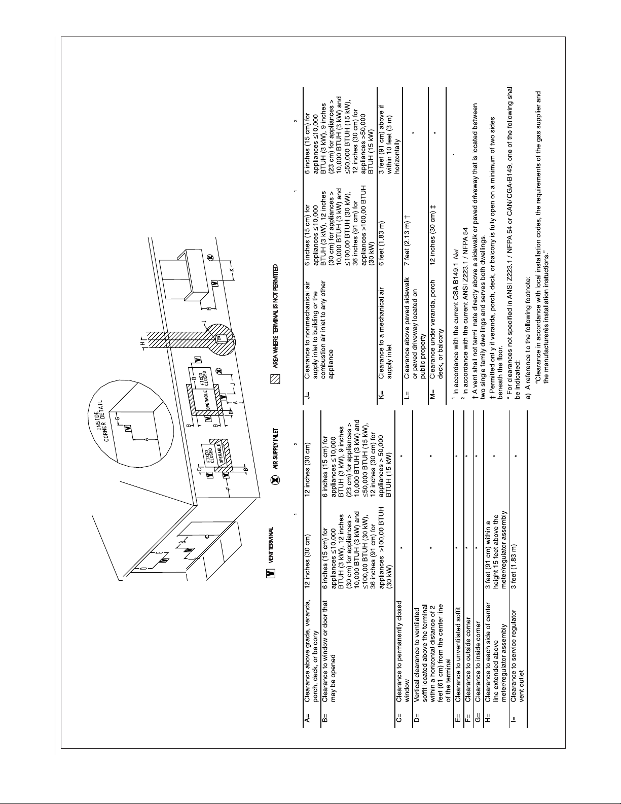
IGURE 24
Natural Gas and Propane Installation Code
National Fuel Gas Code
Canadian Installations
US Installations
Canadian Installations
US Installations
F
DIRECT VENT TERMINAL CLEARANCES≤
32
Page 33
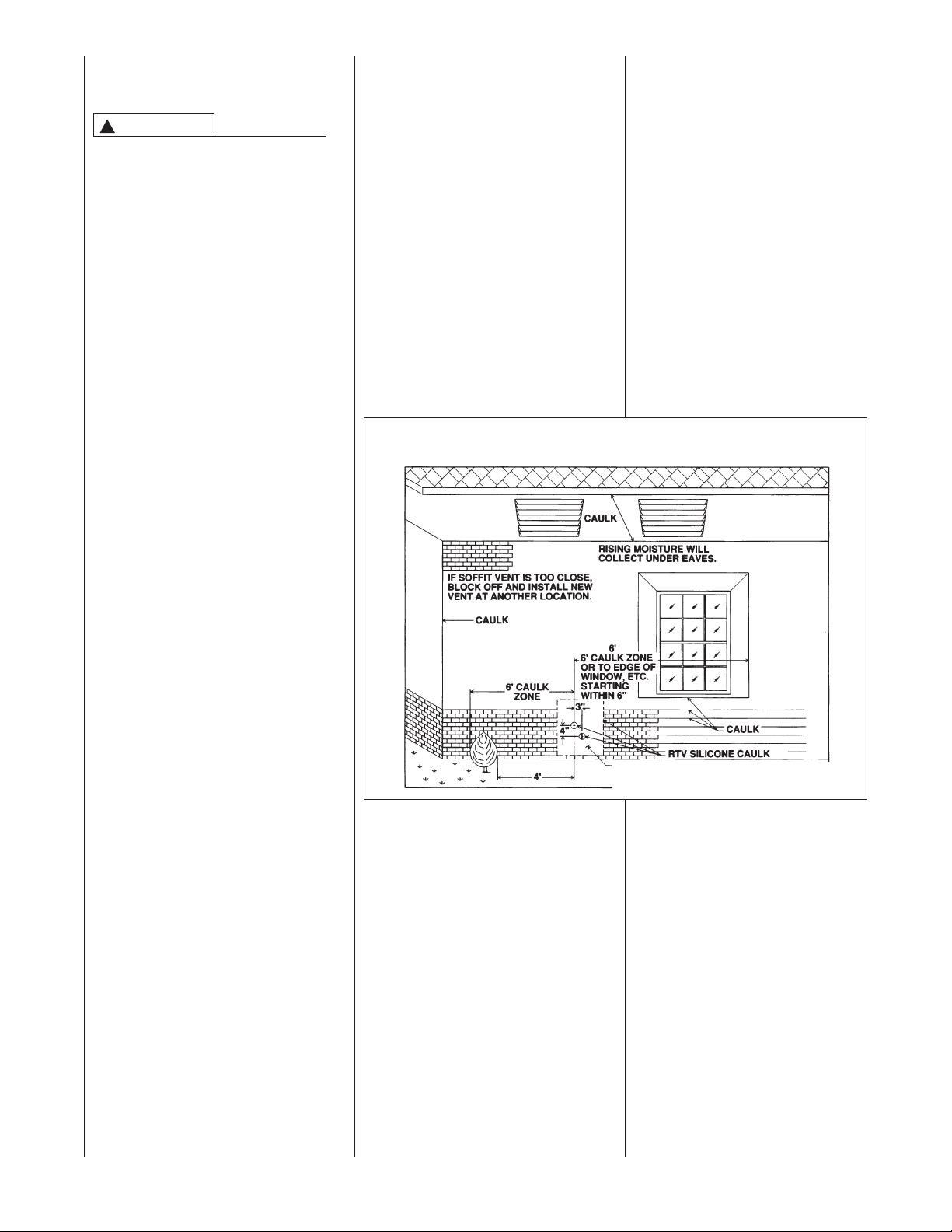
LOCATION REQUIREMENTS
HORIZONTAL DIRECT VENTS
CAUTION
!
THE COMBUSTION PRODUCTS
AND MOISTURE IN THE FLUE
GASES WILL CONDENSE AS THEY
LEAVE THE TERMINATION. THE
ONDENSATE CAN FREEZE ON
C
THE EXTERIOR WALL, UNDER
THE EAVES AND ON
SURROUNDING OBJECTS. SOME
DISCOLORATION TO THE
EXTERIOR OF THE BUILDING IS
TO BE EXPECTED. HOWEVER,
IMPROPER LOCATION OR
INSTALLATION CAN RESULT IN
STRUCTURAL OR EXTERIOR
FINISH DAMAGE TO THE
BUILDING AND MAY
RECIRCULATE PRODUCTS OF
COMBUSTION INTO THE
COMBUSTION AIR TERMINAL AND
FREEZE.
The vent must be installed with the
following minimum clearances. See
Figures 24 & 25.
1. The bottom of the vent terminal
and the air inlet shall be located
at least 12 inches above grade.
Increase the 12-in. minimum to
keep the terminal openings
above the level of snow
accumulation, where applicable.
2. The vent shall not terminate over
public walkways or over an area
where condensate or vapor could
create a nuisance or hazard.
3. The vent terminal shall be
located at least one foot from any
opening through which flue
gases could enter a building.
4. The vent terminal shall be at
least 3 feet above any forced air
inlet located within 10 feet,
except the combustion air inlet of
a direct vent appliance.
5. The vent terminal shall have a
minimum horizontal clearance of
4 feet from electric meters, gas
meters, regulators and relief
equipment.
6. Locate the furnace combustion
air inlet minimum of 3 feet from
the vent of any other gas or fuel
burning appliance or clothes
dryer to prevent recirculation of
the flue gases into the furnace
combustion air inlet. The only
exception to this requirement is
the case of multiventing two or
more furnaces, which is covered
in the section on multiventing in
these instructions.
In addition to the minimum
clearances listed above, the vent
location should also be governed
by the following guidelines.
1. Do not terminate under any
ind of patio or deck. If running
k
the vent under a deck, insulate
it to insure no condensate
reezes and blocks the pipe.
f
. Do not terminate behind any area
2
that may allow the flue products
to become stagnant and
ecirculate.
r
. Do not locate on the side of a
3
building with prevailing winter
winds. This will help prevent
moisture from freezing on walls
and overhangs (under eaves).
4. Do not extend vent directly
through brick or masonry
FIGURE 25
MOISTURE ZONES
surfaces, unless a rust-resistant
sheet metal or plastic backing
plate behind vent. See Figure 25.
5. Do not locate too close to shrubs
as condensate may stunt or
kill them.
6. Minimum vertical clearances of 1
foot are recommended for
overhangs up to 1 foot horizontal.
The vertical clearance should be
increased equally for each
additional increase in horizontal
overhang to a maximum vertical
clearance of 6 feet.
7. Caulk all cracks, seams and
joints within 6 feet horizontally
and above and below vent.
See Figure 25.
2 FT. SQ. SHEET METAL PLATE ON BRICK OR
MASONRY SURFACE RECOMMENDED, BUT
NOT REQUIRED BY CODE.
33
Page 34
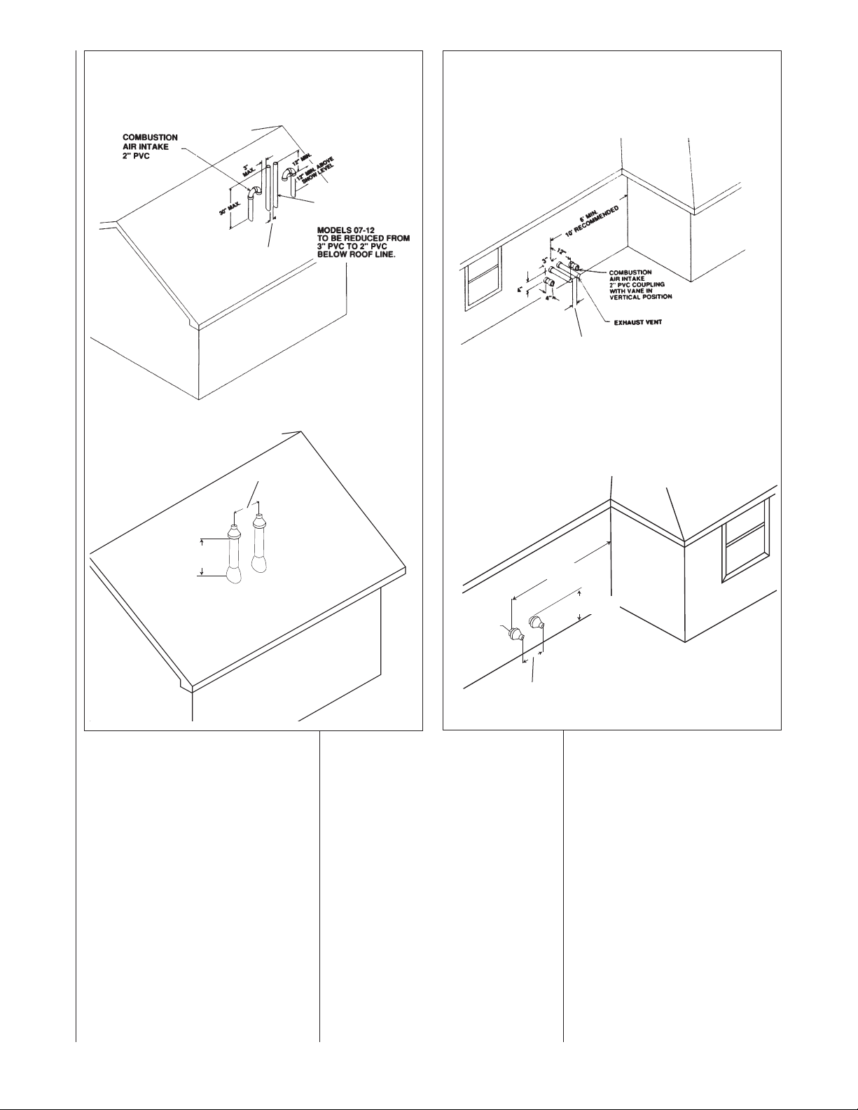
IGURE 26
8"
MINIMUM 12" ABOVE AVERAGE
SNOW ACCUMULATION. MAXIMUM
O
F 24 IN. ABOVE ROOF.
8"
MAXIMUM 1"
DISTANCE
FROM WALL
MINIMUM 12"
ABOVE GRADE
6' MINIMUM
10' RECOMMENDED
F
TWO FURNACE VENTING THROUGH ROOF
IGURE 27
F
TWO FURNACE VENTING THROUGH WALL
TWO-PIPE VENTING
EXHAUST VENT
M
TO BE REDUCED TO
1
” MINIMUM
3
24” MAXIMUM
CONCENTRIC VENTING
8” MINIMUM
4” MAXIMUM
2
ODELS 06-07
-1/2” PVC LAST 12”.
TWO-PIPE VENTING
” MINIMUM
3
24” MAXIMUM
CONCENTRIC VENTING
8. Painted surfaces must be sound
and in good condition with no
cracking, peeling, etc. Painted
surfaces will require
maintenance.
9. Do not expose 3" x 2" reducer/
bushing to outdoor ambient
temperatures.
EE CONCENTRIC
S
VENT SECTION
ON PAGE 23
FOR MORE
INFORMATION.
8” MINIMUM
24” MAXIMUM
NOTE: Measurements apply to both
RXGY-E03 and RXGY-G01
MULTIVENTING
IF VENTING TWO OR MORE
FURNACES NEAR EACH OTHER IS
REQUIRED, EACH FURNACE MUST
BE INDIVIDUALLY VENTED – NO
COMMON VENTING IS PERMITTED.
See Figures 26 and 27 for positioning
of the terminations. When more than
two furnaces are to be vented, there
must be at least 4 feet between the
first two furnaces and the third, etc.
34
Page 35
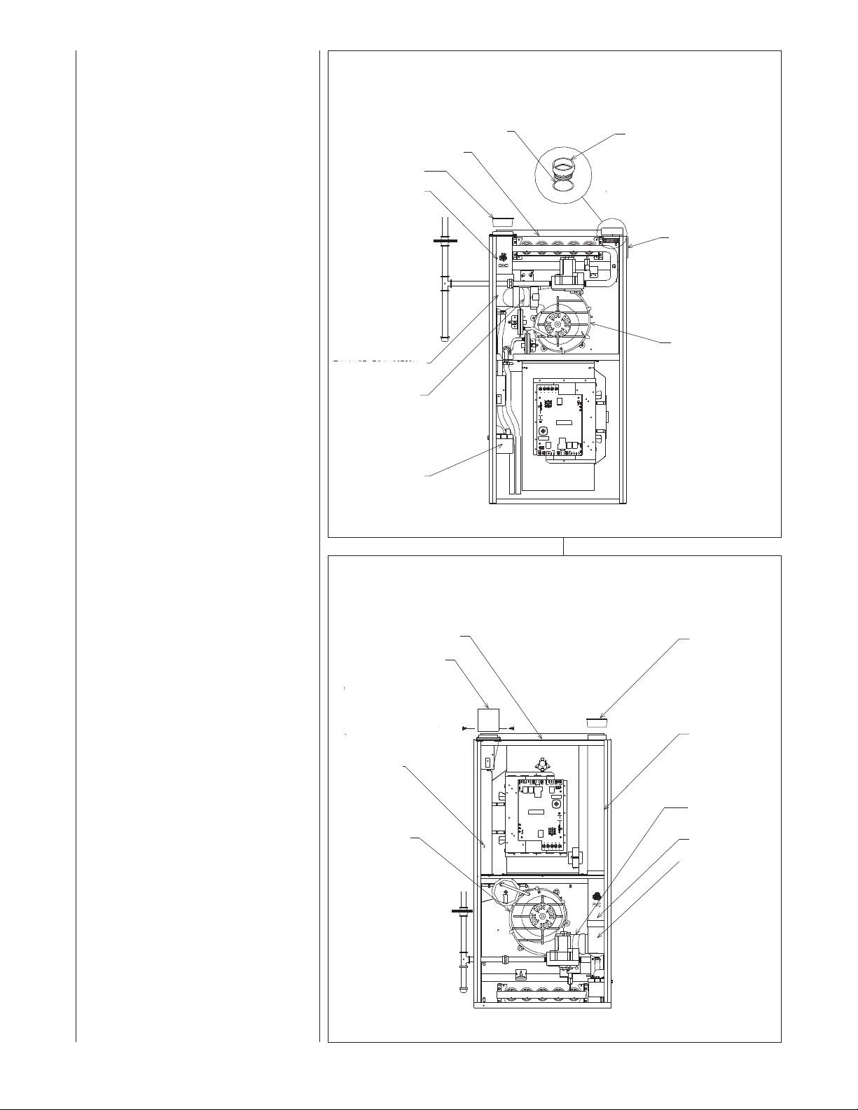
CONNECTING TO FURNACE
IMPORTANT: Clean and debur all
pipe cuts. The shavings must not be
allowed to block the exhaust, inlet or
condensate drain pipes.
UPFLOW FURNACE
The exhaust pipe connection is a 2-in.
female PVC pipe fitting extending
through the left side of the furnace top
plate. This opening has a protective
ap which should be removed just
c
prior to installing the exhaust pipe.
When 2-in. pipe is used, connect it
directly to this fitting. When 3-in. pipe
is used, connect a 2 to 3-in. coupling
to this fitting with a short piece of 2-in.
PVC pipe.
The inlet combustion air connection
is at the right side of the top plate.
An alternate combustion inlet air
connection may be made on the right
side of the jacket. This opening has a
plastic cap. A combustion inlet air
connection fitting is supplied with the
furnace and it must be installed in the
furnace by screwing it into the
opening. Make sure the rubber
“O-ring” supplied with the furnace is
used with this fitting. See Figure 28.
IGURE 28
F
UPFLOW COMBUSTION AIR AND VENT PIPE CONNECTION
“O” RING
TOP PLATE
VENT CAP/PLUG
OUTLET AIR PIPE
XHAUST TRANSITION
E
CONNECTOR
CONDENSATE TRAP
OMBUSTION
C
AIR ADAPTER
NOTE:
WHEN COMBUSTION AIR INLET IS IN
PTIONAL POSITION SWAP LOCATION
O
OF INLET AIR ADAPTER AND “O” RING
WITH PLUG.
PLUG OPT. COMBUSTION
AIR INLET POSITION
NDUCED DRAFT
I
BLOWER
329
I
DOWNFLOW/HORIZONTAL
FURNACE
The exhaust pipe connection is a 2-in.
upflow only PVC pipe fitting extending
through the right side of the furnace
top cover. This opening has a protective cap which should be removed
just prior to installing the exhaust
pipe. When 2-in. pipe is used, connect it directly to this fitting. When
3-in. pipe is used, connect with a
2- to 3-in. coupling directly to the
2-in. pipe.
The combustion inlet air connection is
a 2-in. extruded hole on the left side
of the top plate. When a 2-in. pipe is
used, attach a 2-in. PVC coupling
over this hole with RTV sealant and
also add two sheet metal screws
through the coupling into the
extrusion to secure it in place, and
add the required piping. When 3-in.
pipe is required, use a 2- to 3-in.
coupling and add the required piping.
See Figure 29.
FIGURE 29
DOWNFLOW/HORIZONTAL COMBUSTION AIR AND VENT PIPE CONNECTION
TOP PLATE
COUPLING
NOTE:
ATTACH COUPLING TO
EXTRUDED COLLAR
WITH TWO SCREWS. PUT
BEAD OF SILICONE
AROUND BASE BEFORE
MOUNTING COUPLING.
COMBUSTION
AIR CHASE
INDUCED DRAFT
BLOWER
EXHAUST TRANSITION
VENT CAP/PLUG
PIPE - PVC
CONNECTOR
OUTLET AIR PIPE
I329
35
Page 36
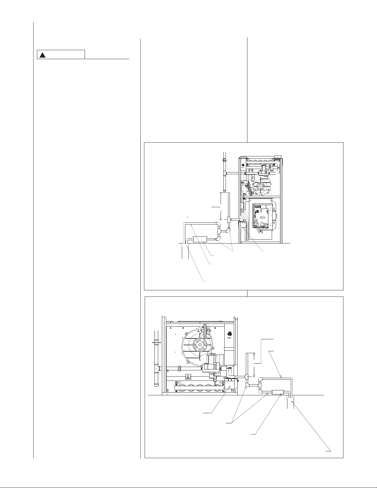
CONDENSATE DRAIN/NEUTRALIZER
GENERAL INFORMATION
CAUTION
!
O NOT RUN DRAIN OUTDOORS.
D
FREEZING OF CONDENSATE CAN
CAUSE PROPERTY DAMAGE.
IMPORTANT: Do not connect into a
common drain line with an air conditioner evaporator coil drain located
below the furnace. A blocked or
restricted drain line can result in overflow of the coil pan and negate the
furnace blocked drain shutoff control.
FILL TRAP ASSEMBLY WITH
WATER BEFORE OPERATING THE
FURNACE. This can be done by
removing the drain hose
from the trap and pouring about a
cup of water into the vent trap. Water
will flow into the house drain when the
trap is full.
If local codes require, install a
condensate neutralizer cartridge in the
drain line. Install cartridge in horizontal
position only. Also install an overflow
line if routing to a floor drain. See
Figures 30 and 31.
If no floor drain is available, install a
condensate pump that is resistant to
acidic water. Pumps are available from
your local distributor. If pump used is
not resistant to acidic water, a
condensate neutralizer must be used
ahead of the pump. The condensate
pump must have an auxiliary safety
switch to prevent operation of the
furnace and resulting overflow of
condensate in the event of pump
failure. The safety switch must be wired
through the “R” circuit only (low voltage)
to provide operation in either heating or
cooling modes.
drain is present, install a riser which is a
minimum of 10
13
⁄16”. If the furnace is
installed in an attic, crawlspace or other
rea where freezing temperatures may
a
ccur, the furnace drain can freeze
o
hile shut off for long periods of time.
w
Use a solvent cement that is compatible
with PVC material. Cut the drain hoses
to the appropriate length and connect to
the trap with hose clamps. Tighten the
clamps with pliers and check for leaks
after attaching.
DOWNFLOW MODELS
IMPORTANT: There are two options
when choosing a height for the
condensate riser:
FIGURE 30
PFLOW CONDENSATE DRAIN
U
OTE:
N
EE UPFLOW MODEL
S
OTES FOR PIPE
N
EIGHT
H
3
1
16
10
/
NEUTRALIZER CARTRIDGE (OPTIONAL)
OVERFLOW LINE
(REQUIRED ONLY WHEN
OPTIONAL NEUTRALIZER
CARTRIDGE IS USED.)
TO FLOOR DRAIN OR CONDENSATE PUMP
CONDENSATE OVERFLOW: With a
3
1
⁄4 inch riser installed above the tee,
a blocked drain will result in overflow
rom the riser.
f
FURNACE SHUTDOWN: To cause
the furnace to shut down when a
blocked drain is present, install a riser
which is a minimum of 5
furnace is installed in an attic,
crawlspace or other area where
freezing temperatures may occur, the
furnace drain can freeze while shut
off for long periods of time.
Use a solvent cement that is
compatible with PVC material.
DRAIN LINE
CONDENSATE TRAP
1
⁄2”. If the
I408
UPFLOW MODELS
The condensate drain trap is located in
the blower compartment on the lefthand side of the jacket. A short piece of
1
⁄2-in. PVC pipe and a1⁄2-in. tee are
provided. Connect the1⁄2-in. pipe to the
elbow on the trap and the tee to this
pipe so that the open end is upward.
Run a drain tube from the bottom of the
tee to a floor drain or condensate
pump.
IMPORTANT: If installing the unit over
a finished ceiling or living area, be
certain to install an auxiliary condensate
drain pan under the entire unit
extending out under the condensate
tee.
IMPORTANT: There are two options
when choosing a height for the
condensate riser:
CONDENSATE OVERFLOW: With a
1
5
⁄2 inch riser installed above the tee, a
blocked drain will result in overflow from
the riser.
FURNACE SHUTDOWN: To cause the
furnace to shut down when a blocked
36
FIGURE 31
DOWNFLOW CONDENSATE DRAIN
CONDENSATE TRAP
DRAIN LINE
NEUTRALIZER CARTRIDGE
(OPTIONAL)
NOTE:
SEE DOWNFLOW MODEL
NOTES FOR PIPE HEIGHT
OVERFLOW LINE
(REQUIRED ONLY WHEN
OPTIONAL NEUTRALIZER
CARTRIDGE IS USED.)
TO FLOOR DRAIN OR CONDENSATE PUMP
I408
Page 37
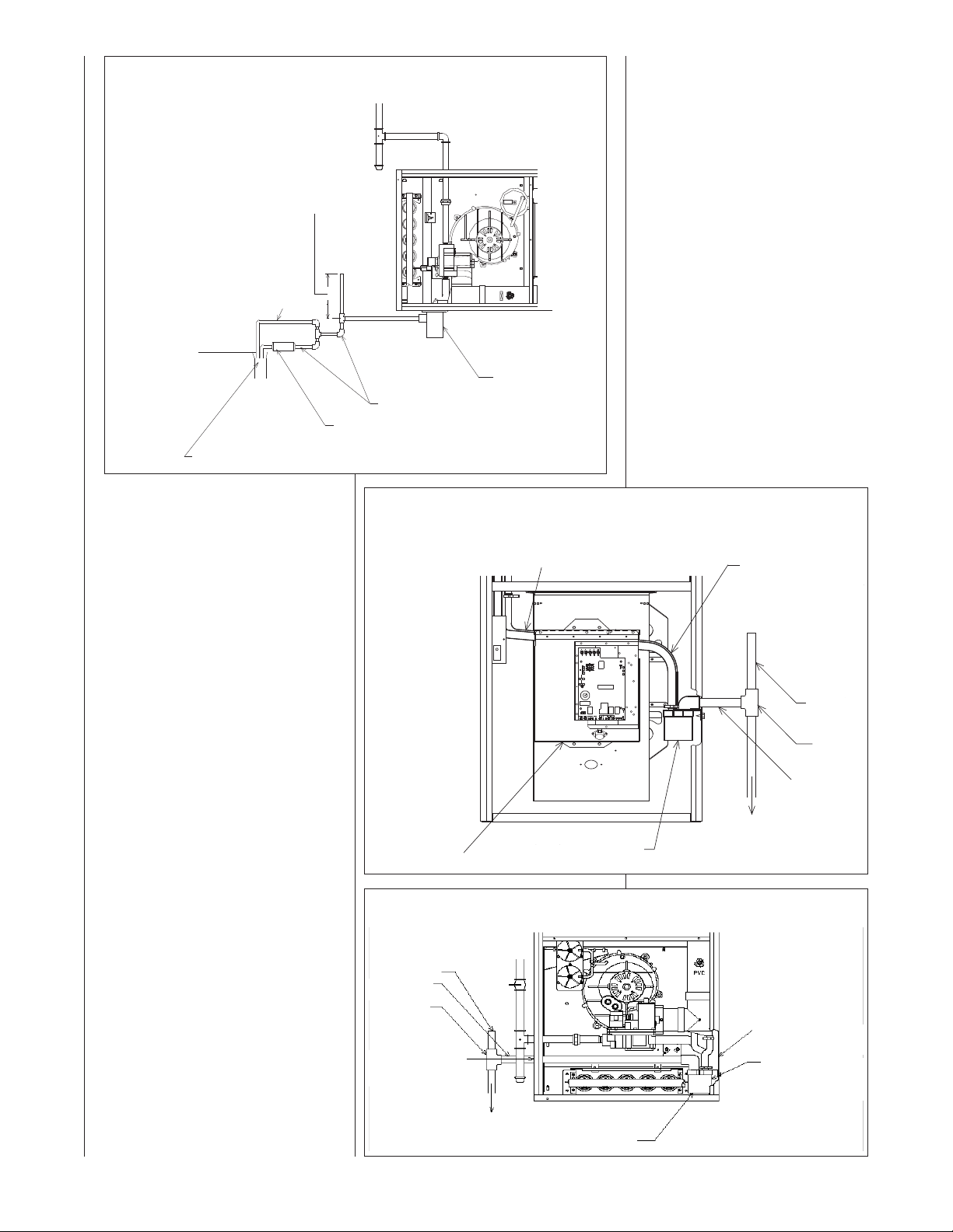
IGURE 32
F
HORIZONTAL CONDENSATE DRAIN
OTE:
N
SEE GENERAL NOTES
FOR HORIZONTAL
ODELS FOR PIPE
M
HEIGHT.
OVERFLOW LINE
REQUIRED ONLY WHEN
(
OPTIONAL NEUTRALIZER
CARTRIDGE IS USED.)
TO FLOOR DRAIN OR CONDENSATE PUMP
RAIN LINE
D
NEUTRALIZER CARTRIDGE
OPTIONAL)
(
ONDENSATE TRAP
C
I
408
DOWNFLOW UNITS
To convert downflow models to lefthand drain, a kit (RXGY-H01) must
be ordered from the distributor. The
kit includes a 24” piece of
1
⁄2” black
PVC pipe, a 2-9/16” length of black
hose, a 2” rubber grommet, a 1-5/8”
plug and instructions. Note the
ocation of the alternate drain hole as
l
shown in Figure 34.
First remove the long molded hose
from the trap. Remove the doubleelbow black molded hose from the
rap and exhaust transition and
t
discard. Remove the trap from its
mounting bracket, rotate it 180°, and
mount in place with drainage elbow
pointing to the left. Reattach the long
black molded hose. Use the 2-9/16”
length of black hose included in the
kit between the trap and exhaust
transition. Clamp the hoses tight with
white nylon clamps.
IMPORTANT: When changing to the
left side, interchange the rubber
bushing on the right side with the hole
REVERSING THE TRAP
UPFLOW UNITS
The trap may be moved to the right
side for right side drainage. Open the
knockout for the drain on the right
side of the cabinet. Remove the
bracket holding the trap from the left
side. Seal the left side drain hole with
a plug provided in the cloth bag with
the furnace. Position the mounting
bracket and trap so that the drain
elbow is centered in the hole on
the right. See Figure 33.
Drill two holes in the cabinet to mount
the bracket. Mount the trap and
bracket to the right side with the drain
elbow pointing through the knockout.
Connect the
noted above. Route the drain hoses
behind the control box, cut to the
appropriate length, and connect to the
trap with hose clamps.
IMPORTANT: DO NOT ALLOW ANY
SAGS OR KINKS IN THE HOSES.
This prevents proper condensate
flow.
IMPORTANT: Do not connect into
a common drain line with an air
conditioner evaporator coil drain
located above the furnace. A blocked
or restricted drain line can result in
overflow of the coil pan and negate
the furnace blocked drain shutoff
control.
1
/2-in. pipe and tee as
FIGURE 33
UPFLOW OPPOSITE SIDE CONDENSATE TRAP CONNECTION
PROPER DRAIN SLOPE REQUIRED
IFC MOUNTING
(NO KINKS ALLOWED)
PLATE
CONDENSATE TRAP
FIGURE 34
DOWNFLOW OPPOSITE SIDE CONDENSATE TRAP CONNECTION
DRAIN VENT
DRAIN
EXTENSION
TEE
ALTERNATE DRAIN HOLE
LOCATED HERE ON JACKET.
(REMOVE PLASTIC PLUGAND
REPLACE WITH GROMMET).
CUT DRAIN HOSES AS
REQUIRED
AND CONNECT TO
INLETS ON TOP
OF CONDENSATE
TRAP
DRAIN
EXTENSION
TO FLOOR
DRAIN
EXISTINGDRAINHOLE. PLUG
WITH 15⁄8” PLUG SUPPLIED
IN KIT
ROTATE TRAP 180° AND
INSTALL RIGID PIPE FROM
ELBOW TO OPPOSITE SIDE
OF JACKET AS SHOWN
DRAIN
RISER
TEE
I394
TO FLOOR
DRAIN OR
CONDENSATE PUMP
CONDENSATE TRAP
I394
37
Page 38

plug on the left side. The hole plug
must be in place to assure that the
control compartment is sealed.
Remove the plug from the 2” alternate
rain hole (see Figure 34) and
d
replace it with the 2” rubber grommet
upplied in the RXGY- H01 downflow
s
alternate drain kit. Also, remove the
1-5/8” grommet supplied in the
primary drain hole and replace it with
the 1-5/8” diameter plug that is also
supplied in the RXGY-H01 downflow
alternate drain kit. Both the hole-plug
and grommet must be in place to
insure a good seal in the burner
ompartment.
c
A length of
1
/2” black PVC pipe is also
provided in the RXGY-H01 downflow
alternate drain kit. Glue one end of
the pipe to the elbow in the trap. Cut
the pipe so that it extends through the
alternate drain hole in the left side of
the cabinet one inch (see Figure 34).
Connect the
1
/2” PVC tee (supplied
with the furnace) to the pipe with a 13/4” riser.
IMPORTANT: Do not connect into a
common drain line with an air
conditioner evaporator coil drain
located above the furnace. A blocked
or restricted drain line can result in
overflow of the coil pan and negate
the furnace blocked-drain shutoff
control.
FILLING THE TRAP
FILL THE TRAP ASSEMBLY WITH
WATER BEFORE OPERATING THE
FURNACE. Do this by removing the
rain hose from the trap or from the
d
connection to the secondary coil.
Pour about a cup of water into the
vent trap. Any excess water flows into
the house drain when the trap is full.
38
Page 39
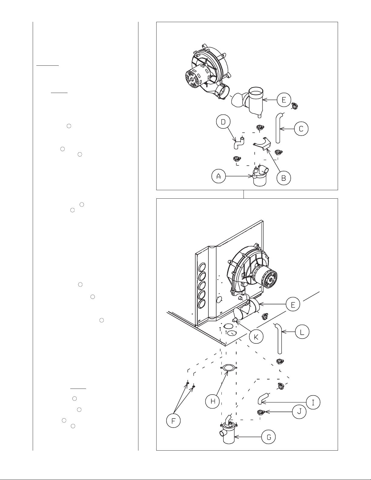
CONDENSATE DRAIN
FOR HORIZONTAL
INSTALLATION
Refer to Figure 35 for Steps 1-4.
This unit is shipped factory ready for
downflow installation. The
condensate trap assembly and drain
hoses require conversion for
horizontal installation. Remove the
existing condensate trap with the unit
in the upright position.
1. Remove the burner compartment
door from the unit.
2. Remove the two screws from the
right side of the furnace jacket
which support the trap mounting
bracket. Remove the two
plastic plugs on either side of the
trap outlet hole and discard.
3. Remove the black molded 90°
hose ➂ from the top of the
existing trap ➂ and from the
furnace collector box. Cut 1.0
inch from the straight end of the
hose. NOTE: Exception–do not
shorten the 90° hose on the 07B
furnace! The 07B has a longer
distance between the collector
box and the horizontal drain trap.
4. Remove the double-elbow black
molded hose ➂ from the exhaust
transition ➂ . Discard this hose
and the downflow trap. Retain
the clamps for future use.
Additional clamps are provided in
the parts bag if any clamps are
damaged during conversion
process.
NOTE: The following steps should
take place with the furnace in the
horizontal position.
Refer to Figure 36 for Steps 6-11.
5. Locate the parts bag in the
burner compartment. Install two
plastic plugs ➅ in the side of the
jacket from bottom side up.
6. Attach the gasket ➇ onto the trap
assembly so that the gasket
holes on the gasket line up with
the holes on the trap assembly.
7. Fill the trap assembly ➆ with a
cup of water.
8. Insert the trap assembly with
gasket up through the existing
hole in the jacket and secure
from inside the jacket. Use two
screws provided. Screw down
into the two “ears” molded into
either side of the trap. Snug the
trap assembly against the
furnace jacket compressing the
gasket slightly to eliminate any
air leaks. Do not
9. Attach the black molded rubber
90° elbow to the straight spout
on the trap top using a white
nylon clamp . Attach the other
end of the rubber elbow to the
spout located on the exhaust
transition using a white nylon
clamp.
B
C
A
D
E
F
H
G
overtighten!
I
J
K
E
IGURE 35
F
PRIGHT POSITION: REMOVAL OF EXISTING DOWNFLOW CONDENSATE TRAP
U
FIGURE 36
HORIZONTAL POSITION: CONDENSATE TRAP INSTALLATION
FOR HORIZONTAL OPERATION
I534
39
Page 40

10. Attach the 90° end of the molded
L
hose to the collector box. Clamp
the hose tight with white nylon
clamp. Then attach the long end of
the molded hose to the 45° elbow
molded into the top of the trap
assembly. Clamp the hose tight
with white nylon clamp.
IMPORTANT: Tighten all clamp
connections with a pair of pliers
and check for leaks after
conversion is complete.
11. IMPORTANT: There are two
options when choosing a height for
the condensate riser:
CONDENSATE OVERFLOW: With
3
⁄4 inch riser installed above the
a 1
tee, a blocked drain will result in
overflow from the riser.
FURNACE SHUTDOWN: To
cause the furnace to shut down
when a blocked drain is present,
install a riser which is a minimum
of 51⁄2”. If the furnace is installed in
an attic, crawlspace or other area
where freezing temperatures may
occur, the furnace drain can freeze
while shut off for long periods of
time. Provisions must be made to
prevent freezing of condensate
(see Figure 2).
Use a solvent cement that is
compatible with PVC material.
NOTE: See location requirements and
combustion section for additional
recommendations.
FILLING THE TRAP
FILL THE TRAP ASSEMBLY WITH
WATER BEFORE OPERATING THE
FURNACE. Do this by removing the
drain hose from the trap or from the
connection to the secondary coil.
Pour about a cup of water into the
vent trap. Any excess water flows into
the house drain when the trap is full.
OTE: Fill the trap assembly with
N
water every heating season.
40
Page 41
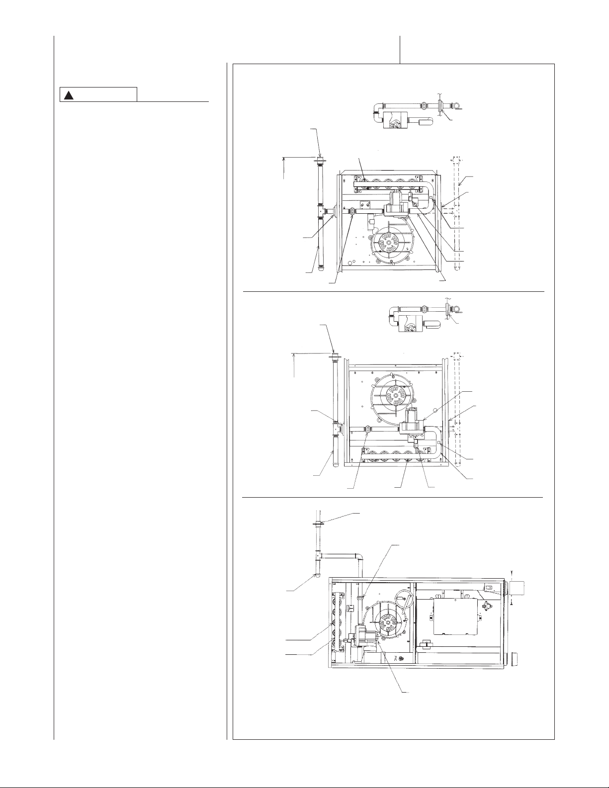
GAS SUPPLY AND PIPING
GAS SUPPLY
WARNING
!
THIS FURNACE IS EQUIPPED AT
THE FACTORY FOR USE ON
NATURAL GAS ONLY.
CONVERSION TO LP GAS
REQUIRES A SPECIAL KIT
SUPPLIED BY THE DISTRIBUTOR
OR MANUFACTURER. MAILING
ADDRESS IS LISTED ON THE
ARRANTY. FAILURE TO USE
W
THE PROPER CONVERSION KIT
CAN CAUSE FIRE, CARBON
MONOXIDE POISONING,
EXPLOSION, PROPERTY
DAMAGE, PERSONAL INJURY OR
DEATH. See the conversion kit
index supplied with the furnace.
This index identifies the proper LP
Gas Conversion Kit required for
each particular furnace.
IMPORTANT: Any additions,
changes or conversions required for
the furnace to satisfactorily meet the
application should be made by a
qualified installer, service agency or
the gas supplier, using factoryspecified or approved parts.
IMPORTANT: Connect this furnace
only to gas supplied by a commercial
utility.
IMPORTANT: A U.L. recognized
fuel gas and CO detector(s) are
recommended in all applications,
and their installation should be in
accordance with the manufacturer’s
recommendations and/or local laws,
rules, regulations or customs.
FIGURE 37
GAS PIPING INSTALLATION
AIN GAS
M
VALVE
TO 5 FEET
4
ABOVE
FLOOR REQ’D
Y SOME
B
UTILITIES.
GROMMET
IN NORMAL
(
POSITION)
DRIP LEG
4 TO 5 FEET ABOVE
LOOR REQ’D BY
F
SOME UTILITIES.
GROMMET
(IN NORMAL
POSITION)
MAIN GAS
ALVE
V
DRIP LEG
U
NION
PFLOW
U
TOP VIEW OF GAS LINE AND VALVE
N OPT. POSITION
I
BURNERS
DOWNFLOW
TOP VIEW OF GAS LINE AND VALVE
IN OPT. POSITION
UNION
BURNERS
HORIZONTAL
MANUAL GAS VALVE
GAS VALVE
IGNITOR
ROMMET
G
OTE: WHEN GAS LINE
N
IS IN OPT. POSITION,
SWAP LOCATION OF
ROMMET AND PLUG.
G
OPT. GAS LINE
OSITION
P
PLUG
(IN NORMAL
OSITION)
P
MANIFOLD
PRESSURE
AP
T
IGNITOR
ANIFOLD
M
GROMMET
OTE: WHEN GAS
N
LINE IS IN OPT.
POSITION, SWAP
OCATION OF
L
GROMMET AND
PLUG.
GAS VALVE
PLUG
(IN NORMAL
POSITION)
MANIFOLD
PRESSURE
TAP
MANIFOLD
I328
GAS PIPING
Install the gas piping according to all
local codes and regulations of the
utility company.
If possible, run a separate gas supply
line directly from the meter to the
furnace. Consult the local gas
company for the location of the
manual main shut-off valve. The gas
line and manual gas valve must be
adequate in size to prevent undue
pressure drop and never smaller
than the pipe size to the combination gas valve on the furnace.
Refer to Table 3 for the recommended gas pipe size. See Figure 37
for typical gas pipe connections.
UNION
DRIP LEG
BURNERS
MANIFOLD
GAS VALVE
I524
IMPORTANT: DO NOT RUN A FLEXIBLE GAS CONNECTOR INSIDE THE
UNIT. Extend the 1/2" black pipe from the gas valve to the outside of the cabinet.
Connect any flexible gas connector from there to the gas piping.
41
Page 42

Install a ground joint union inside
the cabinet to easily remove the
control valve assembly. Install a
manual shut-off valve in the gas
line outside the furnace casing.
The T-valve should be readily
ccessible to turn the gas supply on
a
or off. Install a drip leg in the gas
supply line as close to the furnace as
possible. Always use a pipe
compound resistant to the action of
liquefied petroleum gases on all
threaded connections.
IMPORTANT: When making gas pipe
connections, use a back-up wrench to
prevent any twisting of the control
ssembly and gas valve.
a
ny strains on the gas valve can
A
change the position of the gas orifices
in the burners. This can cause erratic
furnace operation.
IMPORTANT: Do not run a flexible
gas connector inside the unit. If local
codes allow the use of a flexible gas
appliance connector, always use a
new listed connector. Do not use a
connector which has previously
serviced another gas appliance.
Massachusetts law requires that all
flexibile connectors be less than 36ⴖ.
The gas pipe gasket in the cabinet
does not seal around a flexible gas
connector. It is important to have all
openings in the cabinet burner
compartment sealed for proper
furnace operation.
IMPORTANT: ENSURE that the
furnace gas control valve not be
subjected to high gas line supply
pressures.
DISCONNECT the furnace and its
individual shut-off valve from the gas
supply piping during any pressure
testing that exceeds 1/2 PSIG.
(3.48 kPa).
TABLE 3
ATURAL GAS PIPE CAPACITY TABLE (CU. FT./HR.)
N
Capacity of gas pipe of different diameters and lengths in cu. ft. per hr. with pressure drop of 0.3 in. and specific
ravity of 0.60 (natural gas).
g
Nominal Length of Pipe, Feet
ron Pipe
I
ize, Inches 10 20 30 40 50 60 70 80
S
1/2 132 92 73 63 56 50 46 43
/4 278 190 152 130 115 105 96 90
3
1
1-1/4 1,050 730 590 500 440 400 370 350
-1/2 1,600 1,100 890 760 670 610 560 530
1
fter the length of pipe has been determined, select the pipe size which will provide the minimum cubic feet per hour
A
required for the gas input rating of the furnace. By formula:
The gas input of the furnace is marked on the furnace rating plate. The heating value of the gas (BTU/FT3) may be
etermined by consulting the local natural gas utility or the LP gas supplier.
d
however 6⬙ to 7⬙ is recommended.
The minimum supply pressure is 11⬙
w.c. for LP gas.
WARNING
!
NEVER PURGE A GAS LINE INTO
THE COMBUSTION CHAMBER.
NEVER USE MATCHES, FLAME OR
520 350 285 245 215 195 180 170
u. Ft. Per Hr. Required =
C
Gas Input of Furnace (BTU/HR)
eating Value of Gas (BTU/FT
H
3
)
pressure regulator to maintain proper
manifold pressure.
A manual control is on the valve
body. It can be set to only the “ON”
or “OFF” positions. The gas valve is
a slow-opening valve. See Figure 39.
When energized, it takes 6 to 8
seconds to fully open.
ANY IGNITION SOURCE FOR
CHECKING LEAKAGE. FAILURE
TO ADHERE TO THIS WARNING
CAN CAUSE A FIRE OR
EXPLOSION RESULTING IN
PROPERTY DAMAGE, PERSONAL
INJURY OR DEATH.
To check for gas leakage, use an
approved chloride-free soap and
FIGURE 39
TYPICAL GAS VALVES
HONEYWELL
CONTROL REGULATOR
NOB ADJUSTMENT
K
PRESSURE
water solution, an electronic combustible gas detector (see Figure 38),
or other approved method.
GAS VALVE
This furnace has a 24-volt operated
valve. It has ports for measuring
supply pressure and manifold
pressure. The valve body contains a
GAS PRESSURE
Natural gas supply pressure
should be 5" to 10.5" w.c. LP gas
supply pressure should be 11" to
13" w.c. This pressure must be
maintained with all other gas-fired
appliances in operation.
CAUTION
!
ELEVATIONS ABOVE 2000 FT
REQUIRE THAT THE FURNACE
INPUT RATING BE ADJUSTED
AND THAT THE SIZE OF THE
BURNER ORIFICES BE RECALCULATED BASED ON
ELEVATION AND GAS HEATING
VALUE. THE BURNER ORIFICES
MAY (OR MAY NOT) NEED TO BE
CHANGED. SEE THE SECTION
TITLED “HIGH ALTITUDE
INSTALLATIONS” OF THIS BOOK
FOR INSTRUCTIONS.
The minimum supply pressure to the
gas valve for proper furnace input
adjustments is 5⬙ w.c. for natural gas,
42
FIGURE 38
ELECTRONIC COMBUSTIBLE GAS
DETECTOR
ROBERTSHAW
CONTROL KNOB
Page 43

LP CONVERSION
NOTE: See Page 37 for Canadian
High-Altitude Derate
IMPORTANT: LP gas from trucks
used to transport liquid-based
fertilizers can contain chemicals that
will damage the furnace. Verify that
our gas supplier does not use the
y
same trucks to transport materials
other than LP.
The valve can be converted to use
liquefied petroleum (LP) gas by
replacing the pressure regulator
spring with the conversion kit spring.
his LP kit spring allows the regulator
T
to maintain the proper manifold
pressure for LP gas.
NOTE: Order the correct LP
conversion kit from the furnace
manufacturer. Furnace conversion to
LP gas must be performed by a
qualified installer, service agency or
the gas supplier.
ORIFICE INSTALLATION
LP Gas is a manufactured gas that
has consistent heating value across
most regions.
The NFGC guidelines are used with
the following exception:
The recommended LP Gas high
altitude orifice selections differ slightly
in that the NFGC LP orifice chart, as
they are not accurate for Rheem
products. The National Fuel Gas
Code LP orifices are based on an 11⬙
of water column pressure at the
orifice, which differs from Rheem
products that use 10⬙ of water column
at the orifice. This difference requires
a deviation from the NFGC orifice
size recommendations. The Sea
Level input should still be reduced by
4% per thousand ft. and the orifice
size must be selected based on the
reduced input selection chart below.
IGURE 40
F
TYPICAL LP KIT CONTENTS
To change orifice spuds for either
conversion to LP or for elevation:
1. Shut off the manual main gas
valve and remove the gas
manifold.
2. Replace the orifice spuds.
3. Reassemble in reverse order.
4. Turn the gas supply back on and
check for proper operation and
manifold pressure. See Figures
40, 41 and 42.
5. Attach the notice label alerting
the next service technician that
the furnace has been converted
to LP gas.
ORIFICE ORDERING
INFORMATION
Orifice sizes are selected by adding
the 2-digit drill size required in the
orifice part number. Drill sizes
available are 39 through 64; metric
sizes available 1.10mm (-90) and
1.15mm (-91):
Orifice Part Number 62-22175-(drill
size)
Example 1:
#60 drill size orifice required
Part # 62-22175-60
Example 2:
1.15mm drill size orifice required
Part # 62-22175-91
Altitude burner) 15000 Orifice Size
Input (per
0 to 2000 ft. 15000 1.15 mm
(factory)
2000ⴕ-3000ⴕ 13200 1.15 mm
3000ⴕ-4000ⴕ 12600 1.10 mm
4000ⴕ-5000ⴕ 12000 #58
5000ⴕ-6000ⴕ 11400 #59
6000ⴕ-7000ⴕ 10800 #60
7000ⴕ-8000ⴕ 10200 #62
8000ⴕ-9000ⴕ 9600 #63
9000ⴕ-10000ⴕ 9000 #64
43
Page 44

SETTING GAS PRESSURE
he maximum gas supply pressure
T
o the furnace should be 10.5" w.c.
t
atural gas, or 13" w.c. LP gas. The
n
inimum supply gas pressure to the
m
as valve should be 5⬙ w.c. natural
g
as or 11⬙ w.c. LP gas. A properly
g
alibrated U-Tube manometer is
c
equired for accurate gas pressure
r
easurements.
m
CAUTION
!
ELEVATIONS ABOVE 2000 FT
REQUIRE THAT THE FURNACE
INPUT RATING BE ADJUSTED
AND THAT THE SIZE OF THE
BURNER ORIFICES BE RECALCULATED BASED ON
ELEVATION AND GAS HEATING
VALUE. THE BURNER ORIFICES
MAY (OR MAY NOT) NEED TO BE
CHANGED. SEE THE SECTION
TITLED “HIGH ALTITUDE
INSTALLATIONS” OF THIS BOOK
FOR INSTRUCTIONS.
FIGURE 41
MANIFOLD PRESSURE TAP
Supply Gas Pressure Measurement. A line pressure tap is on the
input side of the gas valve. See
Figure 40.
1. With gas shut off to the furnace
at the manual gas valve outside
the unit, remove the input
pressure tap plug.
2. Connect a U-Tube manometer to
the pressure tap.
3. Turn on the gas supply and
operate the furnace and all other
gas-fired units on the same gas
line as the furnace.
4. Note or adjust the line gas
pressure to give:
A. 5⬙ - 10.5⬙ w.c. for natural gas.
B. 11⬙ - 13⬙ w.c. for LP gas.
5. Shut off the gas at the manual
gas valve and remove the
U-Tube manometer.
6. Replace the pressure tap plug
before turning on the gas.
If the supply gas line pressure is
above these ranges, install an in-line
gas regulator to the furnace for
natural gas units. With LP gas, have
the LP supplier reduce the line
pressure at the regulator.
If supply gas line pressure is below
these ranges, either remove any
restrictions in the gas supply piping or
enlarge the gas pipe. See Tables 3
and 4. With LP gas, have the LP
supplier adjust the line pressure at
the regulator.
CAUTION
!
ELEVATIONS ABOVE 2000 FT
REQUIRE THAT THE FURNACE
INPUT RATING BE ADJUSTED
AND THAT THE SIZE OF THE
BURNER ORIFICES BE RECALCULATED BASED ON
ELEVATION AND GAS HEATING
VALUE. THE BURNER ORIFICES
MAY (OR MAY NOT) NEED TO BE
CHANGED. SEE THE SECTION
TITLED “HIGH ALTITUDE
INSTALLATIONS” OF THIS BOOK
FOR INSTRUCTIONS.
TABLE 4
LP GAS PIPE CAPACITY TABLE (CU. FT./HR.)
Maximum capacity of pipe in thousands of BTU per hour of undiluted liquefied petroleum gases (at 11 inches water
column inlet pressure).
(Based on a Pressure Drop of 0.5 Inch Water Column)
Nominal Length of Pipe, Feet
Iron Pipe
Size, Inches 10 20 30 40 50 60 70 80 90 100 125 150
1/2 275 189 152 129 114 103 96 89 83 78 69 63
3/4 567 393 315 267 237 217 196 182 173 162 146 132
1 1,071 732 590 504 448 409 378 346 322 307 275 252
1-1/4 2,205 1,496 1,212 1,039 913 834 771 724 677 630 567 511
1-1/2 3,307 2,299 1,858 1,559 1,417 1,275 1,181 1,086 1,023 976 866 787
2 6,221 4,331 3,465 2,992 2,646 2,394 2,205 2,047 1,921 1,811 1,606 1,496
Manifold Gas Pressure
Measurement. Natural gas
manifold pressure should be 3.5"
w.c. LP gas manifold pressure
should be 10.0" w.c. Only small
variations in gas pressure should be
made by adjusting the pressure
regulator.
1. With the gas to the unit shut off
at the manual gas valve, remove
the pressure tap plug in the gas
manifold. See Figure 41.
2. Connect a U-Tube manometer to
this pressure tap. See Figure 42.
3. Turn on the gas supply and
operate the furnace.
4. Note or adjust the manifold gas
pressure to give:
A. 3.5⬙ w.c. for natural gas.
B. 10.0⬙ w.c. for LP gas.
5. To adjust the pressure regulator,
remove the regulator cap.
6. Turn the adjustment screw
clockwise to increase pressure,
or counterclockwise to decrease
pressure.
7. Securely replace the regulator
cap.
8. Shut off gas at the manual gas
valve and remove the U-Tube
manometer.
9. Replace the manifold pressure
tap plug before turning on
the gas.
Example (LP): Input BTU requirement of unit, 120,000
Equivalent length of pipe, 60 ft. = 3/4" IPS required.
44
Page 45

IGURE 42
F
MANIFOLD PRESSURE READING
FIGURE 43
UPFLOW GROUNDING CONNECTIONS
JUNCTION
BOX
CONDENSATE
TRAP
CONTROL IS GROUNDED WHEN
ATTACHED TO BLOWER
LOW VOLTAGE
TERMINALS
IFC
MOUNTING
PLATE
BLOWER
COMPARTMENT
I409-3
45
Page 46

ELECTRICAL WIRING
NOTE: Electric to furnace must be
supplied by a commercial utility.
Proper voltage is 110-125 volts.
WARNING
!
TURN OFF ELECTRIC POWER AT
FUSE BOX OR SERVICE PANEL
BEFORE MAKING ANY
ELECTRICAL CONNECTIONS.
FAILURE TO DO SO CAN CAUSE
ELECTRICAL SHOCK RESULTING
IN PERSONAL INJURY OR DEATH.
WARNING
!
THE CABINET MUST HAVE AN
UNINTERRUPTED GROUND
ACCORDING TO THE LATEST
EDITION OF THE NATIONAL
ELECTRICAL CODE, ANSI/
NFPA70- OR IN CANADA, THE
CANADIAN ELECTRICAL CODE,
CSA-C221 OR LOCAL CODES
THAT APPLY. DO NOT USE GAS
PIPING AS AN ELECTRICAL
GROUND. A GROUND SCREW IS
PROVIDED IN THE JUNCTION
BOX. FAILURE TO DO SO CAN
CAUSE ELECTRICAL SHOCK
RESULTING IN PERSONAL
INJURY OR DEATH.
WARNING
!
THIS FURNACE IS EQUIPPED
WITH A BLOWER DOOR SAFETY
SWITCH. DO NOT DISABLE THIS
SWITCH. FAILURE TO FOLLOW
THIS WARNING CAN RESULT IN
ELECTRICAL SHOCK, PERSONAL
INJURY OR DEATH.
IMPORTANT: The furnace must be
installed so that the electrical
components are protected from water
(condensate).
Before proceeding with the electrical
connections, be certain that the
voltage, frequency and phase
corresponds to that specified on the
furnace rating plate. For single
furnace application, maximum overcurrent protection is 15 amperes.
Use a separate fused branch
electrical circuit containing a properly
sized fuse or circuit breaker. Run this
circuit directly from the main switch
box to an electrical disconnect that is
readily accessible and located near
the furnace. Connect from the
electrical disconnect to the junction
box on the left side of the furnace,
inside the blower compartment. For
the proper connection, refer to the
appropriate wiring diagram located on
the inside cover of the furnace control
box and in these instructions.
NOTE: UPFLOW MODELS ONLY
The electrical junction box may be
moved to the right side if necessary.
A knockout is provided. Seal the
opposite hole with plug provided.
NOTE: L1 (hot) and L2 (neutral)
polarity must be observed when
making field connections to the
furnace. The ignition control may not
sense flame if L1 and L2 are reversed.
See Figure 44.
Make all electrical connections in
accordance with the latest edition of the
National Electrical Code ANSI/NFPA70
and local codes having jurisdiction.
These may be obtained from:
National Fire Protection
Association, Inc.
Batterymarch Park
Quincy, MA 02269
CSA - International
178 Rexdale Blvd.
Etobicoke (Toronto), Ontario
Canada M9W, 1R3
THERMOSTAT
The room thermostat must be compatible with the integrated furnace
control on the furnace. Generally, all
thermostats that are not of the “current
robbing” type are compatible with the
FIGURE 44
LINE VOLTAGE CONNECTIONS
UT ELECTRONIC CONTROLS 1097-200 CONTROL BOARD
FIGURE 45
ISOLATION RELAY
integrated furnace control. The low
voltage wiring should be sized as
shown.
NOTE: Do not use 24 volt control
wiring smaller than No. 18 AWG.
NOTE: An isolation relay can be
added to prevent any compatibility
problems that may occur. Use a
single-pole, single-throw relay with a
24-volt AC coil. The contacts should
be rated for .5 amps minimum at 24
volts. See Figure 45.
Install the room thermostat in
accordance with the instruction sheet
packed in the box with the thermostat.
Run the thermostat lead wires inside
the blower compartment and connect
to low voltage terminals as shown on
the wiring diagram. Never install the
thermostat on an outside wall or
where it will be influenced by drafts,
concealed hot or cold water pipes or
ducts, lighting fixtures, radiation from
ST-A0804-01
46
Page 47

fireplace, sun rays, lamps, televisions,
radios or air streams from registers.
Refer to instructions packed with the
thermostat for “heater” selection or
adjustment.
ACCESSORIES
FIELD-INSTALLED
OPTION ACCESSORIES
ELECTRONIC AIR CLEANER
(EAC)
NOTE: A spade terminal for EAC is
rovided on these models.
p
HUMIDIFIER
NOTE: Humidifier output is not
available on these models.
ALTERNATE (LEFT SIDE)
DRAIN KIT - RXGY-H01
(DOWNFLOW MODELS
ONLY)
FURNACE TWINNING
INSTALLATIONS
Twinning operation of two furnaces,
nstalled side-by-side, connected by a
i
common duct system with main
power supplied by the same source.
MPORTANT: Twinning of these units
I
requires an accessory twinning kit.
Refer to the specification sheet for
proper kit. Do not attempt to twin
these models by using the
instructions below.
IMPORTANT: Only twin furnaces with
identical control boards.
IMPORTANT: Only bottom returns
can be used. No more than two
furnaces can share the same supply
and return. Furnaces must have
same heating and blower capacity.
Twinning furnaces must operate off
the same phase of power.
It should be noted that both blowers
will run simultaneously when there is
a call for heating, cooling or fan.
The “OK” LED will flash if twinning is
not set up properly.
47
Page 48
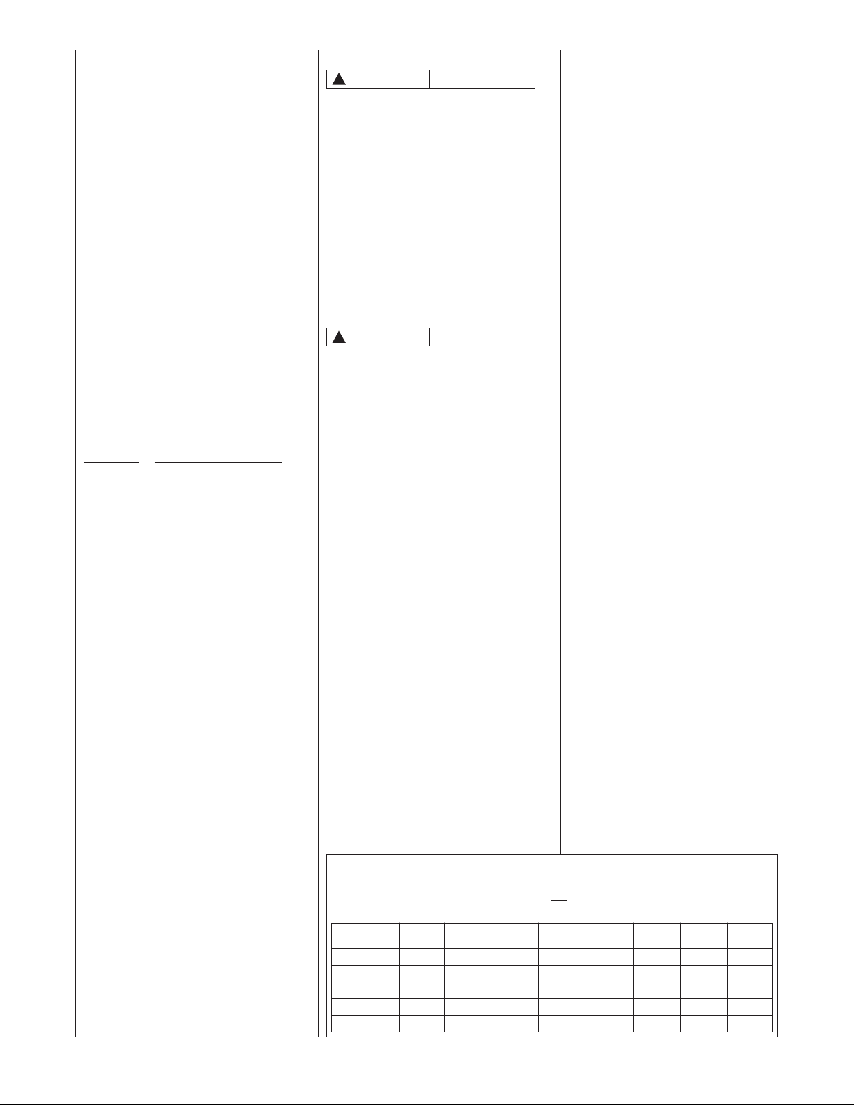
90+ HIGH ALTITUDE
INSTRUCTIONS
90 PLUS CONDENSATING
GAS FURNACES HIGH
ALTITUDE KITS
These models can be converted for
high altitude using the appropriate
High Altitude Conversion Kits listed
below. The kits can be ordered from
the factory. The kit includes pressure
switch(es) and instructions for
converting the furnace for elevations
above 5,000 ft. The kit should never
be used at elevations below 5,000 ft.
In addition, the kit instructions detail
how to re-calculate burner orifice size
based on gas heating value and
elevation. The instructions are based
on a required 4% per thousand feet
reduction in input as specified by the
National Fuel Gas Code (NFGC).
Specific orifices should always be
recalculated for all high altitude
installations as outlined below.
Orifices should be changed, if
necessary, based on gas heating
value and elevation.
High
Altitude Kit BTU Input
RXGY-F04 105,000 BTU’s
RXGY-F05 120,000
RXGY-F06 45,000, 60,000 & 90,000
RXGY-F07 75,000
90 PLUS CONDENSATING
GAS FURNACES HIGH
ALTITUDE OPTION
#278
Some furnaces are available from the
factory already converted for high
altitude elevations. The factory option
for high altitude elevations would be
ordered as a 278 option. These
factory converted furnaces come with
pressure switches for high-altitude
elevations already attached. Also,
different burner orifices are installed
at the factory which are one drill size
smaller (#51 DMS) than standard
90 Plus Condensing Gas Furnaces
(#50 DMS). The smaller orifice is
installed to accommodate for average
heating values expected in most high
altitude areas and a required 4% per
thousand feet reduction in input as
specified by the National Fuel Gas
Code (NFGC). Specific orifices
should always be recalculated for all
high altitude installations as outlined
below. Orifices should be changed, if
necessary, based on gas heating
value and elevation.
NATURAL GAS
NOTE: Factory installed orifices are
calculated and sized based on a sea
!
CAUTION
INSTALLATION OF THIS FURNACE
AT ALTITUDES ABOVE 2000 FT (610
m) SHALL BE IN ACCORDANCE
ITH LOCAL CODES, OR IN THE
W
ABSENCE OF LOCAL CODES, THE
NATIONAL FUEL GAS CODE, ANSI
Z223.1/NFPA 54 OR NATIONAL
STANDARD OF CANADA, NATURAL
GAS AND PROPANE INSTALLATION
CODE, CAN B149.1.
INSTALLATION OF THIS APPLIANCE
AT OR ABOVE 5000 FT (1525 M)
SHALL BE MADE IN ACCORDANCE
ITH THE LISTED HIGH ALTITUDE
W
CONVERSION KIT AVAILABLE WITH
THIS FURNACE.
!
CAUTION
ELEVATIONS ABOVE 2000 FT
REQUIRE THAT THE FURNACE
INPUT RATING BE ADJUSTED AND
THAT THE SIZE OF THE BURNER
ORIFICES BE RE-CALCULATED
BASED ON ELEVATION AND GAS
HEATING VALUE. THE BURNER
ORIFICES MAY (OR MAY NOT) NEED
TO BE CHANGED. THE FOLLOWING
EXAMPLES SHOW HOW TO
DETERMINE IF AN ORIFICE CHANGE
WILL BE NECESSARY AND HOW TO
DETERMINE THE NEW ORIFICE SIZE.
IN CANADA, AS AN ALTERNATE TO
ADJUSTING THE BURNER ORIFICE
SIZE, THE MANIFOLD GAS
PRESSURE MAY BE ADJUSTED.
THIS METHOD IS COVERED LATER
IN THIS SECTION. THIS METHOD OF
ADJUSTING MANIFOLD PRESSURE
MAY ONLY BE USED IN CANADIAN
INSTALLATIONS.
34⬙ 90 Plus furnaces installed at high
elevations require the installation of a
high altitude kit for proper operation. The
high altitude kit consists of a high
altitude pressure switch that replaces
the pressure switch attached to the
induced draft blower. The kit also
contains gas orifices for high altitude.
level Natural Gas heating value of
1075 BTU per cubic ft. Regional
reduced heating values may nullify
the need to change orifices except at
extreme altitudes.
The following are examples of orifice
sizing using the National Fuel Gas
Code Appendix F. For a simplified
estimation of orifice size based on
heating value and elevation, use
ables 5 and 6. However,
T
calculations are the best method.
Example: 900 BTU/ft
Natural Gas Heating Value
I / H = Q
15000 / 900 = 16.68 ft.
I = Sea Level input (per burner):
15000
H = Sea Level Heating Value: 900
Q = 16.68 ft
3
Natural Gas per hour.
From Table F.1 of National Fuel Gas
Code Handbook, 2002 (3.5ⴖ w.c.
column)
Orifice required at Sea Level: #48
From Table F.4 of National Fuel Gas
Code Handbook, 2002
Orifice required at 5000 ft. elevation
(4% de-rate per thousand ft.): #50
Orifice required at 8000 ft. elevation
(4% de-rate per thousand ft.): #51
Example: 1050 BTU/ft
Natural Gas Heating Value
I / H = Q
15000 / 1050 = 14.63 ft.
I = Sea Level input (per burner):
15000
H = Sea Level Heating Value: 1050
Q = 14.28 ft.
3
Natural Gas per hour.
From Table F.1 of National Fuel Gas
Code Handbook, 2002 (3.5ⴖ w.c.
column)
Orifice required at Sea Level: #50
From Table F.4 of National Fuel Gas
Code Handbook, 2002
Orifice required at 5000 ft. elevation
(4% de-rate per thousand ft.): #51
Orifice required at 8000 ft. elevation
(4% de-rate per thousand ft.): #52
The pressure switch must be installed at
elevations above 5000 ft. Elevations
above 2000 ft. require the furnace to be
de-rated 4% per thousand feet.
TABLE 5
Natural Gas Orifice Drill Size (4% per 1000 ft. De-Rate)
IMPORTANT: 90 Plus Models only. Do not use this chart for any 80 Plus Models
Burner Input (per burner) 15,000 BTU @ Sea Level
Annual Avg. Heat
Value (btu per ft
850
900
1000
1075
1170
Sea level
3
to 1999 ft
)
47 48 48 49 49 49 50 50
48 49 49 49 50 50 50 51
49 50 50 50 51 51 51 52
50 51 51 51 51 52 52 52
51 51 52 52 52 53 53 53
2000 to
2999 ft
3000 to
3999 ft
4000 to
4999 ft
5000 to
5999 ft
6000 to
6999 ft
3
Regional
3
3
Regional
3
7000 to
7999 ft
8000 to
8999 ft
48
Page 49
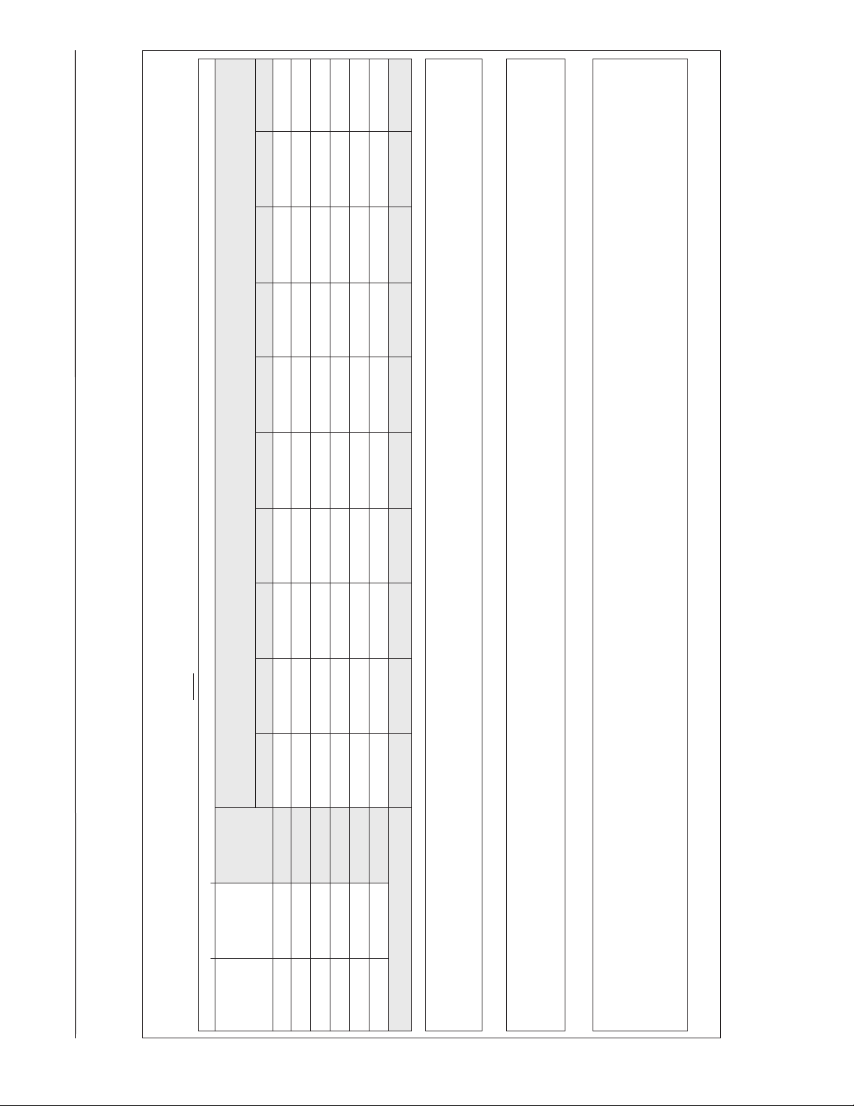
9000-9999
8000-8999
7000-7999
6000-6999
5000-5999
4000-4999
3000-3999
2000-2999
0-999 1000-1999
ELEVATION CHART (NFG recommended orifice based on 4% derate for each 1000 foot of elevation, based
on the intersection of the orifice required at Sea Level and the elevation required below)
Value at
per Burner
15,000 Btu’s
90 Plus Heat
Cubic
Foot at
3.5" W.C.
Sea Level
15,000 14,400 13,800 13,200 12,600 12,000 11,400 10,800 10,200 9,600
46 18.57 808 46 46 47 47 47 48 48 49 49 50
47 17.52 856 47 47 48 48 49 49 49 50 50 51
48 16.36 917 48 48 49 49 49 50 50 50 51 51
Sea
Size
Level
Orifice
NATURAL GAS QUICK REFERENCE CHART FOR ORIFICE SELECTION, AT 3.5" W.C. AND APPROXIMATE FINAL FIRING RATES
90 Plus ONLY models with 15,000 Btu's per Burner. DO NOT USE THIS CHART FOR ANY 80 PLUS MODEL.
TABLE 6
SUPPLEMENTAL ORIFICE SIZE CHART
49 15.2 987 49 49 50 50 50 51 51 51 52 52
Final Firing Rate per Burner
50 13.92 1078 50 50 51 51 51 51 52 52 52 53
51 12.77 1175 51 51 51 52 52 52 52 53 53 53
NOTE:
All calculations are performed by using the first three columns of information only. Before beginning any calculations, determine the
individual burner Btu size and heating value at Sea Level for the installation site. Each value shown in the Heat Value column is per
burner at 3.5" W.C.
Heat Value at Sea Level, for the location of the installation, is available from the Natural Gas Supplier to that site. Orifices for all altitudes are based
on Sea Level values.
burner capacity by the Cubic Foot value for the Heat Value. Once you have either the Cubic Foot Value or the Heat Value you can estimate the Sea
Divide the individual burner capacity (15,000 for 90 plus) by the Heat Value for the site to determine the Cubic Foot value at Sea Level, or divide
these two points on the chart above.
Level orifice for the site. To select the corresponding high altitude orifice, locate the site elevation on the chart above and the orifice required at Sea
Level from your calculation in the first column. The correct high altitude orifice that must be installed in each individual burner is the intersection of
49
Page 50
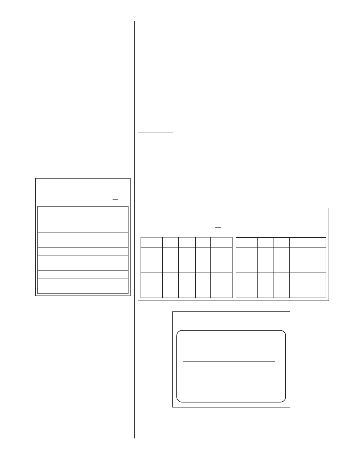
THE MANIFOLD PRESSURE OF THIS APPLIANCE HAS
BEEN FIELD ADJUSTED TO OBTAIN THE CORRECT
INPUT RATING FOR INSTALLATION AT ALTITUDES
BETWEEN 2,000 FEET AND 4,500 FEET ELEVATION.
LA PRESSION DU DISTRIBUTEUR D'ALIMENTATION
DE CET APPAREIL A ÉTÉ AJUSTÉ SUR LES LIEUX AFIN
D'OBTENIR LA BONNE PUISSANCE D'ENTRÉE POUR
UNE INSTALLATION ENTRE 2000 ET 4500 PIEDS
D'ALTITUDE.
92-24399-01-01
LP GAS AT HIGH ALTITUDE
ELEVATIONS
ORIFICE INSTALLATION
LP Gas is a manufactured gas that has
consistent heating value across most
regions.
The NFGC guidelines are used with the
following exception:
The recommended LP Gas high altitude
orifice selections differ slightly in that the
NFGC LP orifice chart, as they are not
accurate for Rheem products. The
National Fuel Gas Code LP orifices are
based on an 11⬙ of water column
pressure at the orifice, which differs from
Rheem products that use 10⬙ of water
column at the orifice. This difference
requires a deviation from the NFGC
orifice size recommendations. The Sea
Level input should still be reduced by 4%
per thousand ft. and the orifice size must
be selected based on the reduced input
selection Table 7.
TABLE 7
P GAS ORIFICE DRILL SIZE
L
(4% PER 1000 FT DE-RATE)
IMPORTANT: 90 Plus Models only. Do not
this chart for any 80 Plus Models
Input (per
Altitude burner) 15000 Orifice Size
0 to 2000 ft. 15000 1.15 mm
2000ⴕ-3000ⴕ 13200 1.15 mm
3000ⴕ-4000ⴕ 12600 1.10 mm
4000ⴕ-5000ⴕ 12000 #58
5000ⴕ-6000ⴕ 11400 #59
6000ⴕ-7000ⴕ 10800 #60
7000ⴕ-8000ⴕ 10200 #62
8000ⴕ-9000ⴕ 9600 #63
9000ⴕ-10000ⴕ 9000 #64
use
(factory)
ORIFICE ORDERING INFORMATION
Orifice sizes are selected by adding the
2-digit drill size required in the orifice
art number. Drill sizes available are 39
p
through 64; metric sizes available
1.10mm (-90) and 1.15mm (-91):
Orifice Part Number 62-22175-(drill
size)
xample 1:
E
# 60 drill size orifice required
Part # 62-22175-60
Example 2:
1.15mm drill size orifice required
art # 62-22175-91
P
The information in Table 8 is based
on a heating value of 1000 BTU per
cubic feet of natural gas, and 2500
BTU per cubic feet of LP gas.
MPORTANT: Actual input rates must
I
be measured on-site with manifold
ressure adjustment to ensure that an
p
actual 10% reduction in input rate is
achieved.
Once this field adjustment has been
made, the label shown in Figure 46
ust be affixed in a conspicuous
m
location on the front of the furnace
cabinet:
NOTE: This label is supplied in the
ALTERNATE METHOD FOR
CANADIAN
HIGH-ALTITUDE
information packet shipped with each
urnace.
f
DERATE
In Canada, unless an orifice change is
specifically mandated by local codes,
an alternate method of altitude deration
through a reduction in manifold
pressure is acceptable as described in
Table 8.
TABLE 8
ALTERNATE METHOD FOR CANADIAN HIGH-ALTITUDE DERATE
IMPORTANT: 90 Plus Models only. Do not use this chart for any 80 Plus Models
NATURAL GAS LP GAS
ORIFICE
ALTITUDE
0’ - 2000’
2001’ - 4500’
INPUT
45,000
0,000
6
75,000
90,000
105,000
120,000
40,500
54,000
67,500
81,000
94,500
108,000
OUTPUT
40,500
4,000
5
67,500
81,000
94,500
108,000
36,450
48,600
60,750
72,900
85,050
97,200
S
#50
#50
IZE
MANIFOLD
P
RESSURE
3.5” W.C.
3.0” W.C.
ALTITUDE
0’ - 2000’
2001’ - 4500’
INPUT
45,000
60,000
75,000
90,000
105,000
120,000
40,500
54,000
67,500
81,000
94,500
108,000
OUTPUT
40,500
54,000
67,500
81,000
94,500
108,000
36,450
48,600
60,750
72,900
85,050
97,200
ORIFICE
SIZE
1.15mm
1.15mm
MANIFOLD
PRESSURE
10” W.C.
7.6” W.C.
50
FIGURE 46
MANIFOLD PRESSURE-CHANGE LABEL
Page 51

START-UP PROCEDURES
A gas furnace’s firing rate, temperature
rise and operation should be checked
after installation. During this process we
recommend that doors and windows be
opened, smoke alarms disabled
temporarily, as furnaces may have some
residual smoke and odor upon initial
operation through the first heating cycle.
We do all we can to control our
manufacturing processes, but it is
possible to have this issue on certain
sizes and models on occasion. Failure
to follow this caution could result in a
nuisance smoke (fire call) or other
smoke or odor complaint from the
customer.
This furnace is equipped with a direct
ignition device. Each time the room
thermostat calls for heat, the ignitor
lights the main burners directly. See the
lighting instructions on the furnace.
TO START THE FURNACE
1. Remove the burner compartment
control access door.
2. IMPORTANT: Be sure that the
manual gas control has been in the
“OFF” position for at least five
minutes. Do not attempt to manually
light the main burners.
3. Turn off the furnace electrical power
and set the room thermostat to its
lowest setting.
4. Turn the gas control knob to the
“ON” position or move the gas
control lever to the “On” position.
5. Replace the burner compartment
control access door.
6. Turn on the furnace electrical power.
7. Set the room thermostat to a point
above room temperature to light the
main burners.
8. After the burners are lit, set the room
thermostat to a desired temperature.
WARNING
!
SHOULD OVERHEATING OCCUR OR
HE GAS SUPPLY FAIL TO SHUT
T
OFF, CLOSE THE MANUAL GAS
VALVE FOR THE APPLIANCE
BEFORE SHUTTING OFF THE
ELECTRICAL SUPPLY. FAILURE TO
DO SO CAN CAUSE AN EXPLOSION
OR FIRE RESULTING IN PROPERTY
DAMAGE, PERSONAL INJURY OR
DEATH.
SEQUENCE OF OPERATION
T ELECTRONIC CONTROLS &
U
INVESYS CLIMATE CONTROLS
UT Electronic Controls Direct Spark
Ignition
1. Each time the thermostat contacts
close, the induced draft blower
(inducer) begins a prepurge cycle.
2. The air proving negative pressure
switch(es) closes.
3. 30 seconds after the pressure
switch(es) close, the spark igniter
energizes. The induced draft blower
operates for the complete heating
cycle.
4. After the spark igniter energizes, the
gas valve opens for a 8 second
trial for ignition.
5. The igniter lights the gas burners.
6. After the gas valve opens the flame
sensor must prove flame ignition
for one second using the process of
flame rectification. If the burners
don’t light, the system goes through
another ignition sequence. It does
this up to four times.
7. The main blower starts 20
seconds after the burners ignite.
8. When the thermostat cycle ends,
the gas valve closes, the burners
go out, the induced draft blower
stops after a 10-second post-
purge, and the negative pressure
switch(es) open.
9. The main blower continues until
timed off by the setting on the
integrated furnace control board.
Sequence if the system doesn’t
light or doesn’t sense flame:
1. On a call for heat, the control
runs the inducer for 30 seconds
to pre-purge.
2. After the 30-second pre-purge,
the spark igniter energizes. The
inducer continues to run.
3. After the spark igniter energizes,
the gas valve opens for an 8second trial for ignition. The
inducer continues and the igniter
stays energized.
4. If flame is not sensed within 8
seconds after the gas valve
opens, the gas valve closes, the
igniter de-energizes and:
5. The inducer completes a 10second post-purge, the inducer
stops, and the control verifies that
the pressure switch has opened.
Once the open pressure switch is
confirmed, the control begins the
next ignition cycle by energizing
the inducer for a pre-purge of 30
seconds. After the pre-purge, the
igniter energizes and the gas
valve opens (inducer continues to
run). If no flame is sensed on the
second attempt, the control goes
into a “self-healing” mode, in
which the blower and the inducer
run for 3 minutes before another
ignition attempt is made.
TO SHUT DOWN
THE FURNACE
1. Set the room thermostat to its lowest
setting and wait for furnace to shut
down.
2. Remove the burner compartment
control access door.
3. Shut off the gas to the main burners
by turning the gas control knob to
the “OFF” position. See Figure 37.
51
Page 52
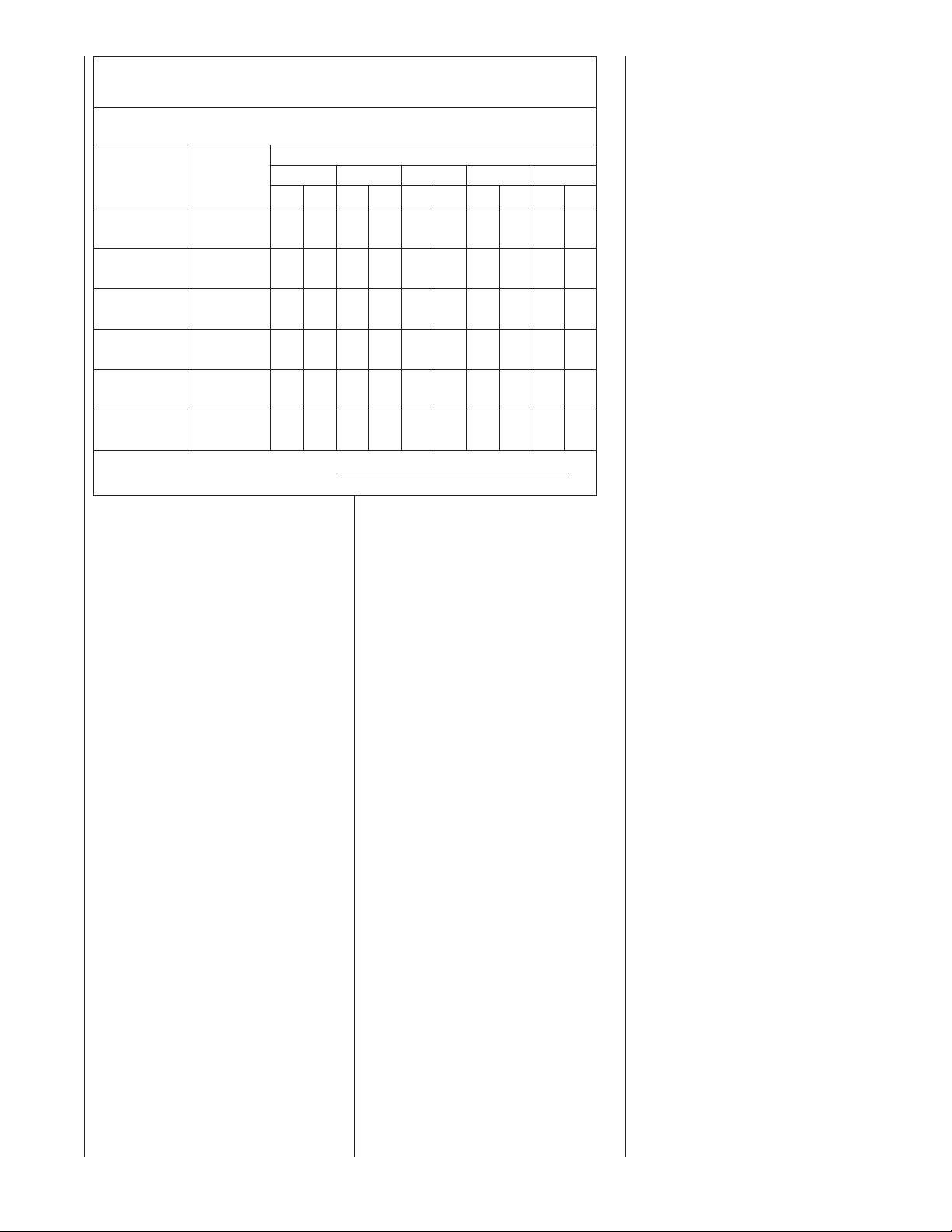
ABLE 9
T
ETER TIME
M
ETER TIME IN MINUTES AND SECONDS FOR NORMAL INPUT RATING OF FURNACES
M
INPUT SIZE
BTU/HR CU. FT. MIN. SEC. MIN. SEC. MIN. SEC. MIN. SEC. MIN. SEC.
45,000 TEN 12 0 13 20 13 50 14 40 33 20
60,000 TEN 9010 0 10 24 11 0 25 0
75,000 TEN 7 12 80819 8 48 20 0
0,000 TEN 60640 70720 16 40
9
05,000 TEN 5 10 5 40 60620 14 20
1
20,000 TEN 4 30 50510 5 30 12 30
1
METER
ONE 1 12 1 20 1 23 1 28 3 20
ONE 0 54 101316230
ONE 0 44 0 48 0 50 0 53 20
ONE 0 36 0 40 0 42 0 44 1 40
O
O
ormula: Input BTU/HR =
F
QUIPPED FOR NATURAL OR LP GAS
E
EATING VALUE OF GAS BTU PER CU. FT.
H
00 1000 1040 1100 2500 (LP)
9
NE 0 31 0 34 0 36 0 38 1 26
NE 0 27 0 30 0 31 0 33 1 15
eating Value of Gas (BTU/FT
H
Time in Seconds (for 1 cu. ft.) of Gas
3
x 3600 x correction factor
)
ADJUSTING OR CHECKING
FURNACE INPUT
The maximum gas supply pressure to
the furnace should be 7" w.c.
for natural gas. The minimum gas
supply pressure for purposes of input
adjustment to the furnace should be 5"
w.c.
A properly calibrated magnehelic gauge
or manometer is required for accurate
gas pressure readings.
The manifold pressure should be set at
3.5" w.c. for natural gas. Only small
variations in the gas flow should be
made by means of the pressure
regulator adjustment. In no case should
the final manifold pressure vary more
than plus or minus 0.3" w.c. from the
above- specified pressures. To adjust
the pressure regulator, remove the
regulator cap and turn the adjustment
screw clockwise to increase pressure or
counterclockwise to decrease pressure.
Then replace the regulator cap securely.
Any necessary major changes in the
gas flow rate should be made by
changing the size of the burner orifices.
To change orifice spuds, shut off the
manual gas valve and remove the gas
manifold. On LP gas furnaces, the LP
gas supply pressure must be set
between 11" and 14" w.c. by means of
the tank or branch supply regulators.
The furnace manifold pressure should
be set at 10" w.c. at the gas control
valve. For elevations up to 2,000 feet,
rating plate input ratings apply. For high
altitudes (elevations over 2,000 ft.), see
conversion kit index for derating and
orifice spud sizes.
Checking furnace input is important to
prevent over firing beyond its designrated input. NEVER SET INPUT
ABOVE THAT SHOWN ON THE
RATING PLATE. Use the following
table or formula to determine input rate.
Start the furnace and measure the time
required to burn one cubic foot of gas.
Prior to checking the furnace input,
make certain that all other gas
appliances are shut off, with the
exception of pilot burners. Time the
meter with only the furnace in
operation.
SETTING INPUT RATE
The furnace is shipped from the factory
with #50 orifices. They are sized for
natural gas having a heating value of
1075 BTU/cu. ft. and a specific gravity
of .60.
Since heating values vary geographically, the manifold pressure
and/or gas orifice size may need to be
changed to adjust the furnace to its
nameplate input. Consult the local gas
utility to obtain the yearly average
heating value and orifice size required
to fire each individual burner at 15,000
BTU/HR.
NOTE: Refer to the National Fuel Gas
Code for high altitude rate adjustment
above 2,000 ft.
52
Page 53
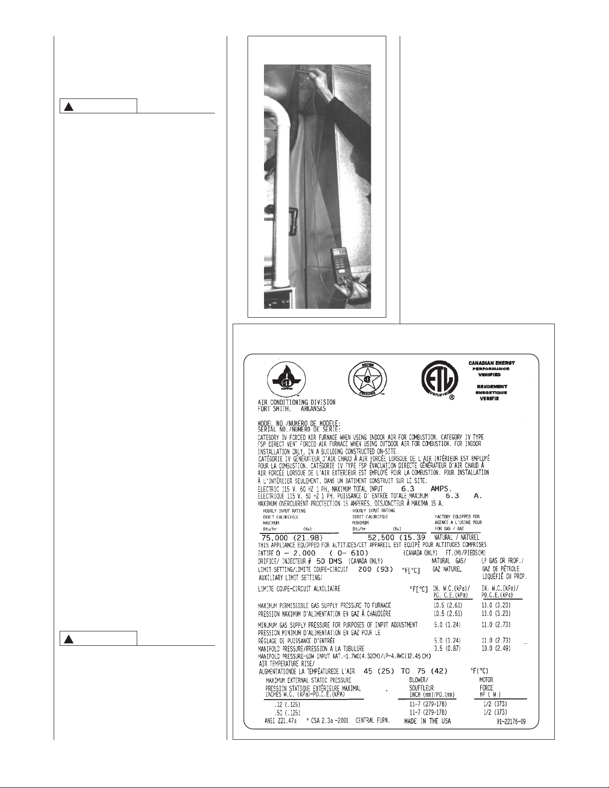
AIR FLOW
The importance of proper air flow over the
heat exchanger cannot be over
emphasized.
CAUTION
!
T IS IMPORTANT THAT EACH DUCT
I
SYSTEM BE SIZED AND INSTALLED
FOR THE SPECIFIC APPLICATION BY
PROPERLY APPLYING THE
APPROPRIATE INDUSTRY ACCEPTED
STANDARD. IF LESS THAN MINIMUM
STANDARDS ARE APPLIED, THE
EQUIPMENT USER COULD EXPECT
TO EXPERIENCE HIGHER UTILITY
BILLS, MAJOR COMPONENT
FAILURE, VARYING DEGREES OF AIR
NOISE OR OTHER UNSATISFACTORY
ISSUES, OVER WHICH THE
MANUFACTURER HAS NO CONTROL.
TEMPERATURE RISE CHECK
To determine if the air flow is correct,
make a temperature rise check.
1. Insert a thermometer in the supply
air duct as close to the furnace as
possible yet out of a direct line from
the heat exchanger. See Figure 47.
2. Insert a thermometer in the return air
duct as close to the furnace as
possible.
3. Operate the furnace.
4. When the thermometer in the supply
air duct stops rising (approximately
five minutes), subtract the return air
temperature from the supply air
temperature. The difference is the
temperature rise.
5. Compare the measured temperature
rise to the approved temperature rise
range listed on the furnace name
plate. See Figure 48.
If the measured temperature rise is above
the approved range, the air flow is too
low. More air must be moved by speeding
up the blower, by removing restrictions in
the duct system, or by adding more
supply or return air duct. If the measured
temperature rise is below the approved
range, the air flow is too much. Use lower
speed tap on the multi-speed blower.
IGURE 47
F
TEMPERATURE RISE MEASUREMENT
FIGURE 48
TYPICAL FURNACE NAME PLATE
INSTALLER MUST ADJUST THE
TEMPERATURE RISE TO THIS
"MIDDLE" POINT AS CLOSELY AS
POSSIBLE. ALSO, THE
TEMPERATURE RISE SHOULD
EVER BE ABOVE OR FALL
N
BELOW THE STATED RANGE.
DOING SO COULD CAUSE
DAMAGE TO THE HEAT
EXCHANGER OR INTERMITTENT
OPERATION WHICH COULD
CAUSE INJURY OR DEATH AND
WILL VOID THE
MANUFACTURER'S WARRANTY
FOR THIS PRODUCT.
WARNING
!
THE MEASURED TEMPERATURE
RISE SHOULD BE AS CLOSE TO THE
MIDDLE OF THE STATED RANGE AS
POSSIBLE. FOR EXAMPLE, IF THE
RISE RANGE IS 40 TO 70 DEGREES,
THE MOST IDEAL RISE WOULD BE 55
DEGREES (THE MIDDLE OF THE RISE
RANGE). IN ALL APPLICATIONS, THE
53
Page 54

TABLE 10
90 PLUS AIR FLOW PERFORMANCE – UPFLOW & DOWNFLOW/HORIZONTAL MODELS
FM @ ESP
TONS BTU INPUT BLOWER/
MOTOR HP .1 .2 .3 .4 .5 .6 .7
PFLOW 11 x 7 /
U
3 45,000 MED-LO 920 [434] 885 [417] 850 [401] 810 [382] 775 [365] 730 [344] 690 [325]
PFLOW 11 x 7 /
U
3 60,000 MED 1060 [500] 1025 [483] 990 [467] 960 [453] 925 [436] 880 [415] 835 [394]
UPFLOW 11 X 7 /
3
75,000 MED 1090 [514] 1050 [495] 1010 [477] 970 [458] 925 [436] 875 [413] 825 [389]
PFLOW 12 X 7 /
U
4 75,000 MED 1480 [698] 1435 [677] 1415 [668] 1390 [656] 1370 [647] 1300 [614] 1255 [592]
PFLOW 12 X 11 /
U
4 90,000 MED 1490 [703] 1465 [691] 1445 [679] 1405 [663] 1375 [649] 1315 [620] 1255 [592]
UPFLOW 12 X 11 /
5
.5 105,000 MED 1710 [807] 1665 [786] 1620 [764] 1580 [746] 1540 [727] 1475 [696] 1410 [665]
4
90,000 MED 1720 [811] 1670 [788] 1620 [764] 1600 [755] 1580 [746] 1520 [717] 1460 [689]
PFLOW 12 X 11 /
U
PFLOW 11 X 10 /
U
5 120,000 MED 1870 [882] 1820 [860] 1775 [838] 1715 [809] 1660 [783] 1590 [750] 1520 [717]
DOWNFLOW/ 11 x 7 /
HORIZONTAL MED-LO 930 [439] 890 [420] 850 [401] 815 [384] 785 [370] 750 [354] 720 [340]
3
45,000 MED-HI 1150 [543] 1120 [528] 1090 [514] 1045 [493] 1002 [473] 950 [448] 900 [425]
DOWNFLOW/ 11 x 7 /
3 HORIZONTAL MED 1115 [526] 1080 [510] 1045 [493] 1005 [474] 965 [455] 920 [434] 875 [413]
60,000 HIGH 1365 [644] 1315 [620] 1270 [600] 1225 [578] 1180 [557] 1125 [491] 1070 [505]
DOWNFLOW/ 11 X 7 /
3 HORIZONTAL MED 1100 [519] 1060 [500] 1025 [484] 980 [462] 940 [443] 890 [420] 845 [399]
75,000 HIGH 1340 [632] 1295 [611] 1250 [590] 1200 [566] 1150 [543] 1090 [514] 1025 [484]
DOWNFLOW/ 12 X 7 /
4 HORIZONTAL MED 1595 [753] 1560 [736] 1525 [720] 1480 [698] 1440 [679] 1380 [651] 1325 [625]
75,000 HIGH 1835 [866] 1780 [840] 1730 [816] 1675 [791] 1625 [767] 1555 [734] 1480 [698]
DOWNFLOW/ 12 X 11 /
4 HORIZONTAL MED 1420 [670] 1400 [661] 1380 [651] 1365 [644] 1350 [637] 1260 [594] 1175 [554]
90,000 HIGH 1605 [757] 1575 [743] 1550 [732] 1560 [736] 1570 [740] 1480 [698] 1395 [656]
DOWNFLOW/ 12 X 11 /
4.5 HORIZONTAL MED 1605 [757] 1575 [743] 1550 [732] 1560 [736] 1570 [740] 1480 [698] 1395 [656]
90,000 HIGH 2005 [946] 1965 [927] 1930 [910] 1890 [892] 1850 [873] 1765 [833] 1680 [793]
DOWNFLOW/ 12 X 11 /
4.5 HORIZONTAL MED 1680 [793] 1645 [776] 1615 [762] 1585 [748] 1560 [736] 1490 [703] 1420 [670]
105,000 HIGH 2055 [970] 2000 [944] 1940 [915] 1880 [887] 1820 [859] 1745 [823] 1675 [790]
DOWNFLOW/ 11 X 10 /
5 HORIZONTAL MED 1840 [868] 1820 [860] 1800 [850] 1750 [826] 1700 [802] 1645 [776] 1590 [750]
120,000 HIGH 2315 [1093] 2250 [1062] 2185 [1031] 2110 [996] 2040 [963] 1965 [927] 1890 [892]
SPEED
1
1
1
OW 805 [380] 780 [368] 760 [358] 720 [340] 685 [323] 645 [304] 605 [285]
⁄2 L
ED-HI 1140 [538] 1110 [524] 1085 [512] 1045 [493] 1010 [476] 950 [448] 890 [420]
M
HIGH 1360 [642] 1320 [623] 1280 [604] 1235 [583] 1195 [564] 1140 [538] 1080 [500]
OW 880 [415] 845 [398] 815 [384] 790 [373] 760 [358] 715 [337] 670 [316]
⁄2 L
IGH 1260 [594] 1215 [573] 1175 [554] 1135 [535] 1100 [519] 1040 [491] 985 [465]
H
⁄2 LOW 880 [415] 850 [401] 825 [389] 785 [370] 750 [354] 702 [331] 655 [309]
HIGH 1300 [613] 1255 [592] 1210 [571] 1160 [547] 1110 [524] 1055 [498] 1005 [474]
3
OW 1290 [609] 1275 [602] 1260 [595] 1220 [576] 1195 [564] 1170 [552] 1140 [538]
⁄4 L
IGH 1705 [805] 1665 [786] 1615 [762] 1570 [741] 1540 [727] 1475 [696] 1400 [661]
H
1
OW 1235 [582] 1210 [571] 1180 [559] 1150 [543] 1120 [528] 1075 [507] 1035 [488]
⁄2 L
IGH 1720 [811] 1670 [788] 1620 [764] 1600 [755] 1580 [746] 1520 [717] 1460 [689]
H
3
⁄4 LOW 1490 [703] 1465 [691] 1445 [679] 1405 [663] 1375 [649] 1315 [620] 1255 [592]
HIGH 2100 [991] 2050 [967] 2000 [944] 1955 [923] 1910 [901] 1825 [861] 1745 [823]
3
OW 1490 [703] 1445 [682] 1405 [663] 1375 [649] 1350 [637] 1295 [611] 1240 [585]
⁄4 L
HIGH 2010 [949] 1955 [923] 1900 [897] 1855 [875] 1810 [854] 1710 [807] 1610 [859]
3
OW 1610 [760] 1580 [746] 1555 [734] 1515 [715] 1475 [696] 1415 [668] 1355 [639]
⁄4 L
IGH 2115 [998] 2050 [967] 1990 [939] 1945 [917] 1900 [897] 1795 [847] 1690 [795]
H
1
⁄2 LOW 820 [387] 790 [373] 760 [359] 725 [342] 690 [326] 650 [306] 610 [288]
HIGH 1414 [667] 1365 [644] 1320 [622] 1270 [599] 1220 [576] 1165 [550] 1115 [526]
1
⁄2 LOW 910 [429] 885 [418] 860 [406] 815 [384] 770 [363] 725 [342] 680 [321]
1
⁄2 LOW 890 [420] 860 [406] 835 [394] 790 [373] 750 [354] 705 [332] 660 [311]
3
⁄4 LOW 1405 [668] 1375 [649] 1350 [637] 1310 [618] 1270 [599] 1235 [583] 1195 [564]
1
⁄2 LOW 1155 [545] 1125 [531] 1100 [519] 1080 [510] 1060 [500] 1000 [472] 940 [443]
3
⁄4 LOW 1420 [670] 1400 [661] 1380 [651] 1365 [644] 1350 [637] 1260 [594] 1175 [554]
3
⁄4 LOW 1460 [689] 1425 [672] 1390 [656] 1375 [649] 1360 [642] 1280 [604] 1200 [566]
3
⁄4 LOW 1590 [750] 1565 [738] 1540 [727] 1505 [710] 1475 [696] 1425 [672] 1375 [649]
NOTE: CFM values represent furnace-only airflow ratings.
C
54
Page 55
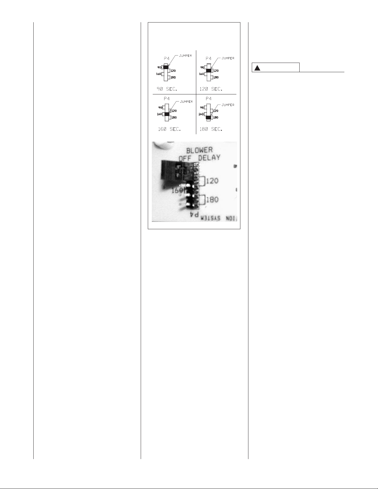
SETTING BLOWER
TIMINGS
NOTE: This does not apply to these
odels. The heat tap functions as the
m
continuous fan tap as well.
See Figure 49 for instructions for
setting the blower “OFF” timings.
If cooling speed and fan speed are
esired to be the same, this may be
d
accomplished by not connecting “Y”
to the integrated furnace control.
If desired for cool, fan and heat to all
be the same speed, then “piggyback”
jumper “H/C” to “FAN” and do not
connect “Y” to the integrated furnace
control. Do not connect anything to
“H” or “C.”
IGURE 49
F
UT Electronic Controls 1097-200
BLOWER OFF TIMINGS
GAS FURNACE (DIRECT
DRIVE) INSTRUCTIONS
FOR CHANGING BLOWER
SPEED
WARNING
!
DISCONNECT THE ELECTRICAL
UPPLY TO THE FURNACE
S
BEFORE ATTEMPTING TO
CHANGE THE BLOWER SPEED.
FAILURE TO DO SO CAN CAUSE
ELECTRICAL SHOCK RESULTING
IN PERSONAL INJURY OR DEATH.
The blower motor is wired for blower
speeds required for normal operation
as shown.
If additional blower speed taps are
available, speeds may be changed if
necessary to fit requirements of the
particular installation. Check motor
lead color for speed designation.
Heating speeds should not be
reduced where it could cause the
furnace air temperature to rise to
exceed the maximum outlet air
temperature specified for the unit.
IMPORTANT: Always check air
temperature rise after changing the
heating speed for any reason.
55
Page 56
MAINTENANCE
WARNING
!
THESE INSTRUCTIONS ARE
INTENDED AS AN AID TO
UALIFIED SERVICE
Q
PERSONNEL FOR PROPER
INSTALLATION, ADJUSTMENT
AND OPERATION OF THIS UNIT.
READ THESE INSTRUCTIONS
THOROUGHLY BEFORE
ATTEMPTING INSTALLATION
OR OPERATION. FAILURE TO
FOLLOW THESE INSTRUCTIONS
MAY RESULT IN IMPROPER
INSTALLATION, ADJUSTMENT,
SERVICE OR MAINTENANCE,
POSSIBLY RESULTING IN FIRE,
ELECTRICAL SHOCK, CARBON
MONOXIDE POISONING,
EXPLOSION, PROPERTY
DAMAGE, PERSONAL INJURY
OR DEATH.
DISCONNECT MAIN ELECTRICAL
POWER TO THE UNIT BEFORE
ATTEMPTING ANY MAINTENANCE. FAILURE TO DO SO CAN
CAUSE ELECTRICAL SHOCK
RESULTING IN PERSONAL
INJURY OR DEATH.
ABLE 11
T
ILTER SIZES
F
PFLOW FILTER SIZES
U
PART FURNACE INPUT BOTTOM SIDE
O. WIDTH MBTUH SIZE SIZE
N
4-24094-01 17
5
4-24094-02 21" 75B, 90, 105 19
5
54-24094-03 24
PART FURNACE INPUT
N
4-22699-01 17
5
4-22699-01 21" 90, 105 12" X 20" 2
5
54-22699-02 24
1
45, 60, 75A 15
/2"
1
/2" 120 223/4" X 25" 153/4" X 25" 1
OWNFLOW FILTER SIZES
D
O. WIDTH MBTUH
1
/2"
1
/2" 120 14" X 20" 2
3
/4"
1
/4"
45, 60, 75 12" X 20" 2
3
X 25" 15
3
X 25" 15
IZE QUANTITY
S
FILTERS
NOTE: These models do not come
from the factory with filters installed.
Filters must be field installed. See
Table 11.
Keep the filters clean at all times.
Vacuum dirt from filter, wash with
detergent and water, air dry
thoroughly and reinstall.
Keep the filters clean at all times.
Vacuum dirt from filter, wash with
detergent and water, air dry
thoroughly and reinstall.
NOTE: Some filters must be resized
to fit certain units and applications.
See Table 11 and Figure 50.
1. 21” - 90,000 & 105,000 BTUH
2. 24.5” - 120,000 BTUH unit
UANTITY
Q
X 25" 1
/4"
X 25" 1
/4"
units require removal of a
3.5-in. segment of filter and
frame to get the proper width
for a side filter.
requires removal of a 7" segment
of filter and frame to get the
proper width for a side filter.
56
Page 57
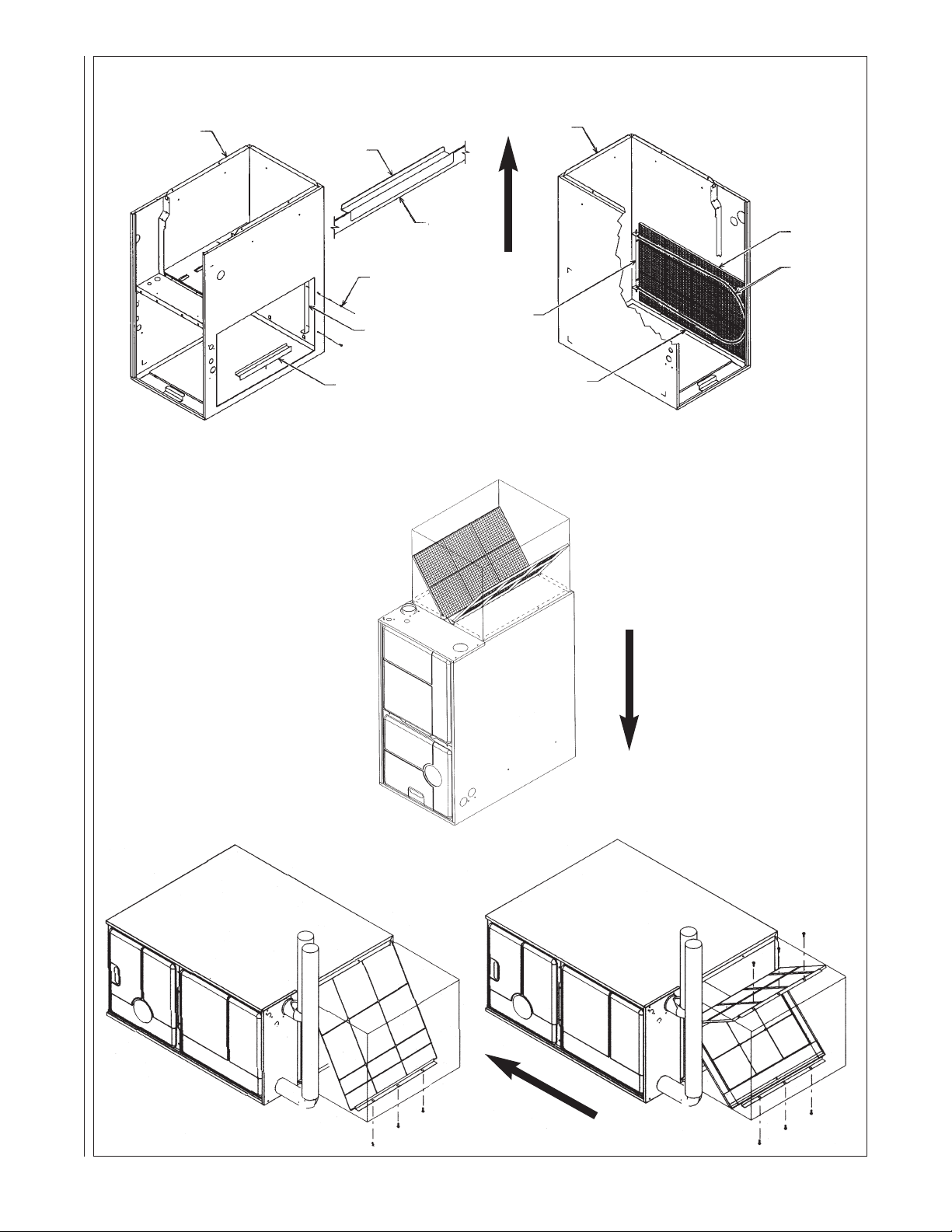
IGURE 50
FILTER AND ROD ASSEMBLY
D
FILTER
SUPPORT
A
NGLE
F
ILTER
FILTER
R
OD
JACKET
I332
I413
I528
HORIZONTAL
JACKET
J
ACKET
A
NGLE
FILTER ROD
SUPPORT
A
NGLE
FILTER SUPPORT
ANGLE
(SEE ANGLE DETAIL)
ATTACH WITH
SHEET METAL
SCREWS (2 REQÕD)
A
NGLE DETAIL
ROD & FILTER SUPPORT ANGLE ASSEMBLY
F
ILTER LOCATIONS
F
UPFLOW
FILTER
ILTER ROD
F
SUPPORT
ANGLE
FILTER SUPPORT
NGLE
A
(SEE ANGLE DETAIL)
AIRFLOW
FILTER ROD
UPPORT
S
ANGLE
DOWNFLOW
FILTER
SUPPORT
NGLE
A
AIRFLOW
FILTER
OD
R
45-24095-01
AIRFLOW
57
Page 58

CAUTION
!
DO NOT OPERATE THE SYSTEM
FOR EXTENDED PERIODS
WITHOUT FILTERS.
A PORTION OF THE DUST
ENTRAINED IN THE AIR MAY
TEMPORARILY LODGE IN THE AIR
DUCT RUNS AND AT THE SUPPLY
REGISTERS. ANY RECIRCULATED
UST PARTICLES WILL
D
BE HEATED AND CHARRED BY
CONTACT WITH THE FURNACE
HEAT EXCHANGER.
THIS RESIDUE WILL SOIL
CEILINGS, WALLS, DRAPES,
CARPETS AND OTHER
HOUSEHOLD ARTICLES.
LUBRICATION
IMPORTANT: DO NOT attempt to
lubricate the bearings on the blower
motor or the induced draft blower
motor. Addition of lubricants can
reduce the motor life and void the
warranty.
The blower motor and induced draft
blower motor are permanently
lubricated by the manufacturer and do
not require further attention.
The blower motor and induced draft
blower motor must be cleaned
periodically by a qualified installer,
service agency, or the gas supplier to
prevent the possibility of overheating
due to an accumulation of dust and
dirt on the windings or on the motor
exterior. And, as suggested
elsewhere in these instructions, the
air filters should be kept clean. Dirty
filters can restrict airflow. The motor
depends upon sufficient air flowing
across and through it to keep from
overheating.
SYSTEM OPERATION
INFORMATION
Advise The Customer
1. Keep the air filters clean. The
heating system will operate
better, more efficiently and more
economically.
2. Arrange the furniture and drapes
so that the supply air registers
and the return air grilles are
unobstructed.
3. Close doors and windows. This
will reduce the heating load on
the system.
4. Avoid excessive use of kitchen
exhaust fans.
. Do not permit the heat generated
5
by television, lamps or radios to
influence the thermostat
operation.
6. Except for the mounting platform,
keep all combustible articles 3
feet from the furnace and vent
system.
7. IMPORTANT: Replace all blower
doors and compartment covers
after servicing the furnace. Do
not operate the unit without all
panels and doors securely in
place.
8. Explain proper operation of the
system with constant air
circulation.
ANNUAL INSPECTION
• The furnace should operate for
many years without excessive scale
build-up in the flue passageways.
However, it is recommended that a
qualified installer, service agency, or
the gas supplier annually inspect
the flue passageways, the vent
system and the main burners for
continued safe operation. Pay
particular attention to deterioration
from corrosion or other sources.
• IMPORTANT: It is recommended
that at the beginning and at
approximately half way through the
heating season, a visual inspection
be made of the main burner flames
for the desired flame appearance by
a qualified installer, service agency
or the gas supplier. If the flames are
distorted and/or there is evidence of
back pressure, check the vent and
inlet air system for blockage. If there
is carbon and scale in the heat
exchanger tubes, the heat
exchanger assembly should be
replaced.
WARNING
!
HOLES IN THE VENT PIPE OR
HEAT EXCHANGER CAN CAUSE
TOXIC FUMES TO ENTER THE
HOME, RESULTING IN CARBON
MONOXIDE POISONING OR
DEATH. THE VENT PIPE OR HEAT
EXCHANGER MUST BE
REPLACED IF THEY LEAK.
• IMPORTANT: It is recommended
that at the beginning of the heating
season, the flame sensor be
cleaned with steel wool by a
qualified installer, service agency or
the gas supplier.
• IMPORTANT: It is recommended
that at the beginning of the heating
season, the condensate trap be
inspected for debris or blockage. A
blocked condensate trap can cause
water to back up into the primary
heat exchanger and lead to
nuisance tripping of the
overtemperature switches.
• IMPORTANT: It is recommended
that at the beginning of the heating
season, the condensate neutralizer
if used be replaced by a qualified
installer, service agency or the gas
supplier.
• IMPORTANT: It is recommended
that an annual inspection and
cleaning of all furnace markings be
made to assure legibility. Attach a
replacement marking, which can be
obtained through the distributor, if
any are found to be illegible or
missing.
REPLACEMENT PARTS
See sheet enclosed with furnace for
replacement part information.
TROUBLESHOOTING
Refer to Figure 51 for determining
cause of unit problems.
WIRING DIAGRAMS
Figures 52 and 53 are complete
wiring diagrams for the furnace and
power sources.
58
Page 59

IGURE 51
GO TO
E
WARNING
INTEGRATED FURNACE CONTROL (IFC)
TROUBLESHOOTING GUIDE
HAZARDOUS VOLTAGE
LINE VOLTAGE
CONNECTIONS
DISCONNECT POWER BEFORE SERVICING.
SERVICE MUST BE BY A TRAINED, QUALIFIED
SERVICE TECHNICIAN.
N
OTE: Most failures are not due to the IFC. Double check all other
possibilities, including the ground connection, before replacing the IFC.
N
OTE:
A
lways verify gas valve inlet and outlet gas
pressure.
KEY TO ABBREVIATIONS
IBM = Indoor Blower Motor
IDM = Induced Draft Motor
IFC = Integrated Furnace Control
PS = Pressure Switch(es)
SE = Spark Electrode
HSI = Hot-Surface Ignition
DSI = Direct-Spark Ignition
FLAME (AMBER) LED CODES
OFF = No Flame Present
R
APID BLINK = Unexpected Flame
S
LOW BLINK = Marginal Flame Sense
S
TEADY ON = Normal Flame Sense
B
LINK CODES(GREEN LED)
1 Blink - Soft lockout
R
eset System power and
start over from beginning
2
Blinks - PS Circuit open
go to point “F.”
3
Blinks - Limit circuit open
g
o to point “D.”
4
Blinks - PS Circuit closed
G
o to point “G.”
5 Blinks - Twin Fault (Optional)
*Go to point “H.”
1) Set FAN switch to “AUTO”
2) Set thermostat to call for heat (set temp. differential to greater than 10°F
D
oes the IDM Energize?
IDM Runs for 30 sec. pre-purge?
S
park Ignitor Electrode (SE) Energizes
o
r HSI Ignitor Glowing?
D
oes Main Bur
ner Light and stay lit?
Is the gas valve energized?
PS dropping out?
Check IFC*
Does IBM star
t on heat speed 20 seconds
after bur
ners light?
Does main burner remain lit until
heat call ends?
Does ther
mostat maintain reasonable room
temperatur
e near setpoint?
Set thermostat to off position (W to C = ØV)
Does gas valve shut off immediately?
Does IDM shut off after ten second post-purge?
Does IBM shut of
f after a max. of 3 min?
END
Heat-mode troubleshooting
“POWER” LED ON?
2
4V on W to IFC?
I
s “STATUS” LED blinking,
steady-on, or off?
Check IFC*.
Check IFC*.
Does IDM run
indefinately
.
Does IDM Run for 60 sec. and then of
f for Five minutes
-
Check thermostat in “heat” mode,
battery, wire, and connections.
S
EE BLINK CODES
-
Check 24V at IFC.
- Check Fuse.
-
Check Door Switch and Line Power.
- Check Transformer.
-
Check Breaker.
-
Check PS contacts
- Check wires for short.
- Check IFC*.
- Check switches and hoses for
water or moisture
- For Twinned units, check that both IFCs are set for “TWIN” and wires
are connected between “TWIN” terminals.
-
Check IFC*.
-
For twinned units, ensure transformers are in phase.
(
if out of phase, flame LED will be dim).
-
For non-twinned units, ensure “TWIN” is in the single (OFF) position.
-
For Twinned units – ensure both IFC‘s have same part number.
-
Check PS, PS Hoses, and wires.
-
Check for blocked vent, excessive vent length or elbows, or
b
locked heat exchanger.
- Check IDM wired correctly.
- Ensure against excessive wind, which can open pressure switch.
- If downflow 90+, check aux. limit – shoud be closed
- Check for intermittent P.S. operation.
- Check switches and hoses for water or moisture.
- Check gas supply and manifold pressure.
- Ensure L1 and Neutral not swapped on IFC and junction box.
- Check SE alignment.
- Check orifice or other restrictions to gas flow.
-
C
heck flame sense rod (clean with sandpaper).
-
Check flame carry over.
- Check wires, continuity, and connection between IFC and gas valve.
-
Ensure 24 V between appropriate pins on connector of IFC.
-
Ensur
e manual switch on valve is in the “ON” position.
- 90+ check aux. limit open? Should be closed
- 90+ upflow models – check drain pressure switch between IFC and
gas valve – should be closed – replace drain pressure switch if drain
is not blocked or clear drain if blocked.
- Did a pressure switch open during ignition trial? If yes, go to F
- Did a limit open during ignition trial? If yes, go to D
- Check line voltage between “HEAT” and “NEUTRAL” on IFC.
- Check wires, connections, and continuity between IFC and IBM.
- Check IBM capacitor.
-
Check IBM.
CHECK:
- grounding on IFC and unit.
- check for proper polarity between L1 & neutral.
- flame sense rod (clean if necessary).
- wire continually between flame sense rod and appropriate pin of
connector on IFC
- flame carries across all burners, and all burners stay lit.
CHECK:
AIRFLOW - ensure no restrictions, such as dirty filter, dampers, closed registers, etc.
LIMITS - ensure good wire and connections between IFC and all limits. Make sure
limits ar
e not open when circulating air temperature is within a specified range.
ROLLOUTS
- ensure rollouts or overtemperature limits do not need to be reset. Make
sure no flame rollout in burner compartment due to blocked flu or heat exchanger.
OVERFIRE - ensure furnace is not overtemperature (temp rise is above stated range).
Check gas valve, proper orifice size, gas pressure, etc.
Is Limit circuit or IDM wire through aux. limit open or
opening and closing?
Note: IFC Status LED should be blinking a Fault Code 3.
Is the IFC sensing a good flame: NOTE:
Flame sense light should be steady-on
when bur
ners are lit. If flame LED blinking,
or off, flame sense is low or absent.
Ensure thermostat is properly placed and not improperly affected by
registers, fans, sunlight, heat through walls, pipes, or wires in walls.
- Check heat anticipator setting. Furnace may need an isolation relay.
- Check installation instructions under section titled “Isolation Relay” for
details.
- Verify correct furnace sizing.
NOTE: If IFC goes into lockout (“ST
ATUS LED will blink code “1”), shut
off main power to unit, wait 30 seconds and then reset power.
PROBLEM
STILL
PRESENT
“STATUS” LED
BLINKING
“FLAME” LED BLINKING
OR STEADY ON
If “E” did not
resolve issue
Double check - Is W off at IFC?
(W to C = ØV?)
Voltage present at gas valve?
- Check gas valve.
SEE BLINK CODES
- Check IFC*.
Check IFC*.
*Most failur
es are not due to the IFC. Double
check all other possibilities, including the
gr
ound connection or wir
e connections, before
replacing the IFC.
Ensure TSTAT is not in “FAN” position.
Is “STATUS” LED blinking?
Is “FLAME” LED blinking or steady-on?
**System will attempt to light 4 times. V
oltage
is present at gas valve for only 7 seconds during each trial for ignition. The entir
e system will
go into a 1 hour lockout after 4 attempts. The
main blower and IDM will run 180 seconds
between 2nd and 3rd ignition attempts.
- Check line voltage at IDM.
- Check wires and connections between IDM and IFC.
- Ensure line voltage on IDM pins of IFC connector.
- Check IDM capacitor (90+ only).
CHECK BLINK CODES
- Check for open limit or limit circuit.
- Check for intermittent PS operation.
- Check for vent restrictions.
- Ensure vent lengths not excessive or
too small diameter.
- Check for blocked heat exchanger.
FOR SPARK IGNITION
- Check SE wire & connections.
- Clean SE with sandpaper. Replace SE if necessary.
-
I
f problem persists, check IFC*.
- Check SE gas and proper SE ground.
- Check SE wire for spark arcing to metal before electrode.
FOR HOT SURFACE IGNITION
- Check ignitor connected.
-
Check ignitor wires.
-
Check ignitor r
e
sistance. If open circuit, low or high resistance, replace.
- Check ignitor for fractures or cracking
- Check ignitor placement.
- If problem persists, check IFC*.
START
REPEAT THIS PROCEDURE UNTIL TROUBLE-FREE OPERATION IS OBTAINED.
N
O
NO
NO
I
f “
I
”
did not
r
esolve issue.
NO NO
NO
N
O
NO
NO
NO
NO
NO
NO
NO
N
O
NO
N
O
NO
B
LINKING
YES
YES
Y
ES
YES
YES
YES
YES
YES
YES
YES
YES
YES
YES
YES
YES
YES
YES
YES
STEADY-ON
I
D
F
H
E
G
YES
NO
YES
PREPURGE
IGNITION TRIAL
IBM “ON” DELAY
STEADY HEAT
END HEA
T CALL
POST-PURGE
IBM “OFF” DELAY
STEADY OFF
N
O
OFF
*
*
92-101654-01-00
GO TO
F
GO TO
I
F
PFLOW MODELS W/INTEGRATED FURNACE CONTROL (IFC) UT Electronic Controls 1012-925 (115 VAC IGNITER)
U
59
Page 60

IGURE 52
F
OR MODELS WITH UT ELECTRONIC CONTROLS 1027-200 INTEGRATED FURNACE CONTROL AND DIRECT SPARK IGNITION
F
60
Page 61

FIGURE 53
FOR MODELS WITH UT ELECTRONIC CONTROLS 1027-200 INTEGRATED FURNACE CONTROL AND DIRECT SPARK IGNITION
61
Page 62

626364
Page 63

Page 64

CM 1009
 Loading...