

Page 1
Service Manual
Packaged Terminal
Air Conditioners & Heat Pumps
7,000-15,000 BTUH
Cooling with Electric Heat
EKTC07-1G
EKTC09-1G
EKTC12-1G
EKTC15-1G
Heat Pump with Electric Heat
EKTH07-1G
EKTH09-1G
EKTH12-1G
EKTH15-1G
EKTC07-2G
EKTC09-2G
EKTC12-2G
EKTC15-2G
EKTH07-2G
EKTH09-2G
EKTH12-2G
EKTH15-2G
Heat Controller • 1900 Wellworth Ave. • Jackson, MI 49203 • (517)787-2100 • www.heatcontroller.com
Page 2
PACKAGED TERMINAL A/C SERVICE MANUAL Heat Controller
UNIT NOMENCLATURE
EKTC 07 - 1 G
EKTC—Cooling only with Electric Heat
EKTH—Heat Pump with Electric Heat
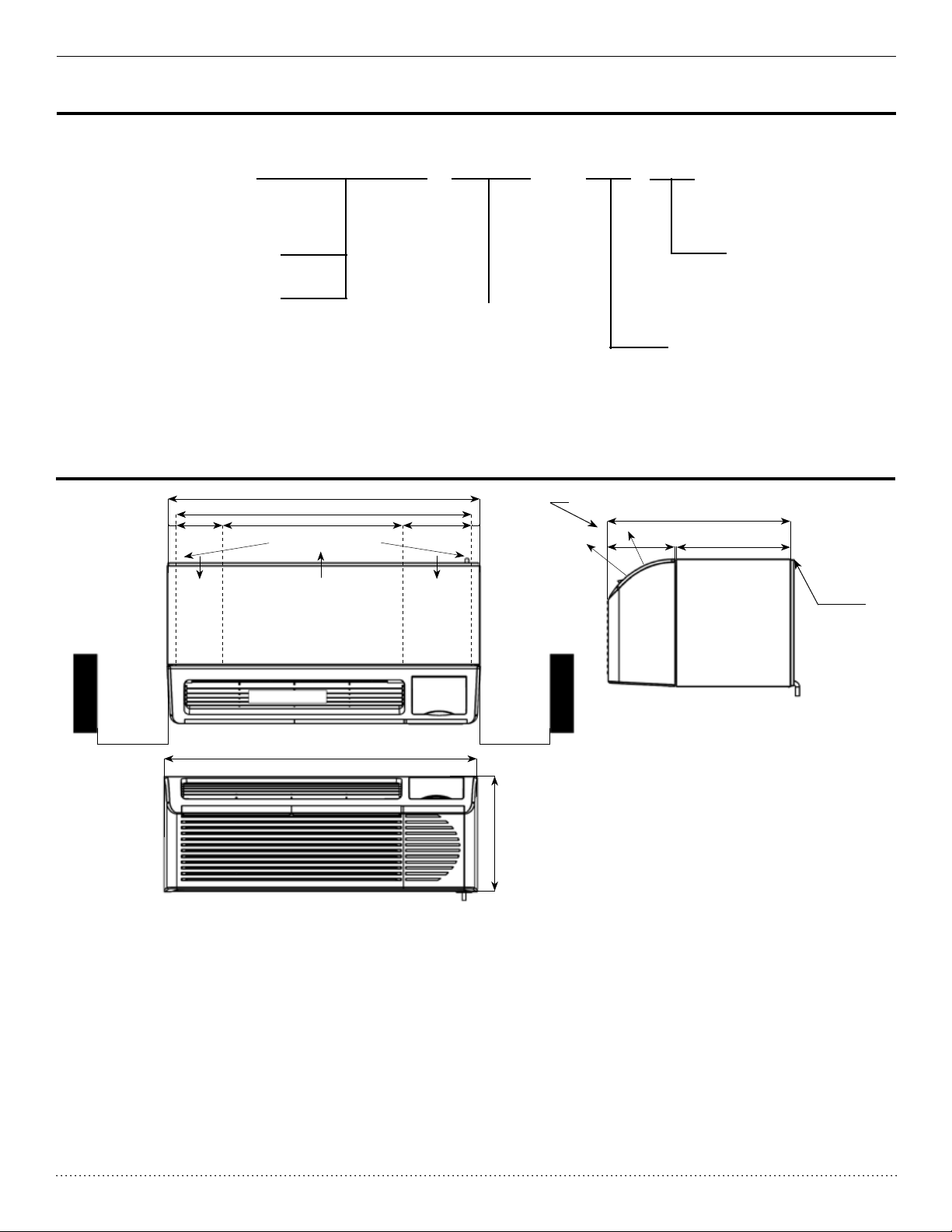
DIMENSIONAL DATA
1”
U
AIR DISCHARGE GRILLE
42”
40”
24”6”
Location of external drain holes
on bottom ange of wall sleeve
AIR OUTLETAIR INLET AIR INLET
Top View
10”
CONTROL DOOR
BTU/H
07K
09K
12K
15K
1”
MODEL REVISION
G=Green R-410A
VOLTAGE CODE
1=208/230V-60Hz
2=265V-60Hz (consult factory)
AIR DISCHARGE GRILLE IS REVERSIBLE TO
PROVIDE EITHER 40° OR 80°DISCHARGE ANGLE
80°
40°
8”
22”
13.75”
Refrigerant Gas
ARCHITECTURAL
OR STAMPED
GRILLE
2”min Clearance
to side walls
LEFT
42”
RIGHT
Front View
2”min Clearance
to side walls
16”
1
Page 3
Heat Controller SERVICE MANUAL Packaged Terminal A/C
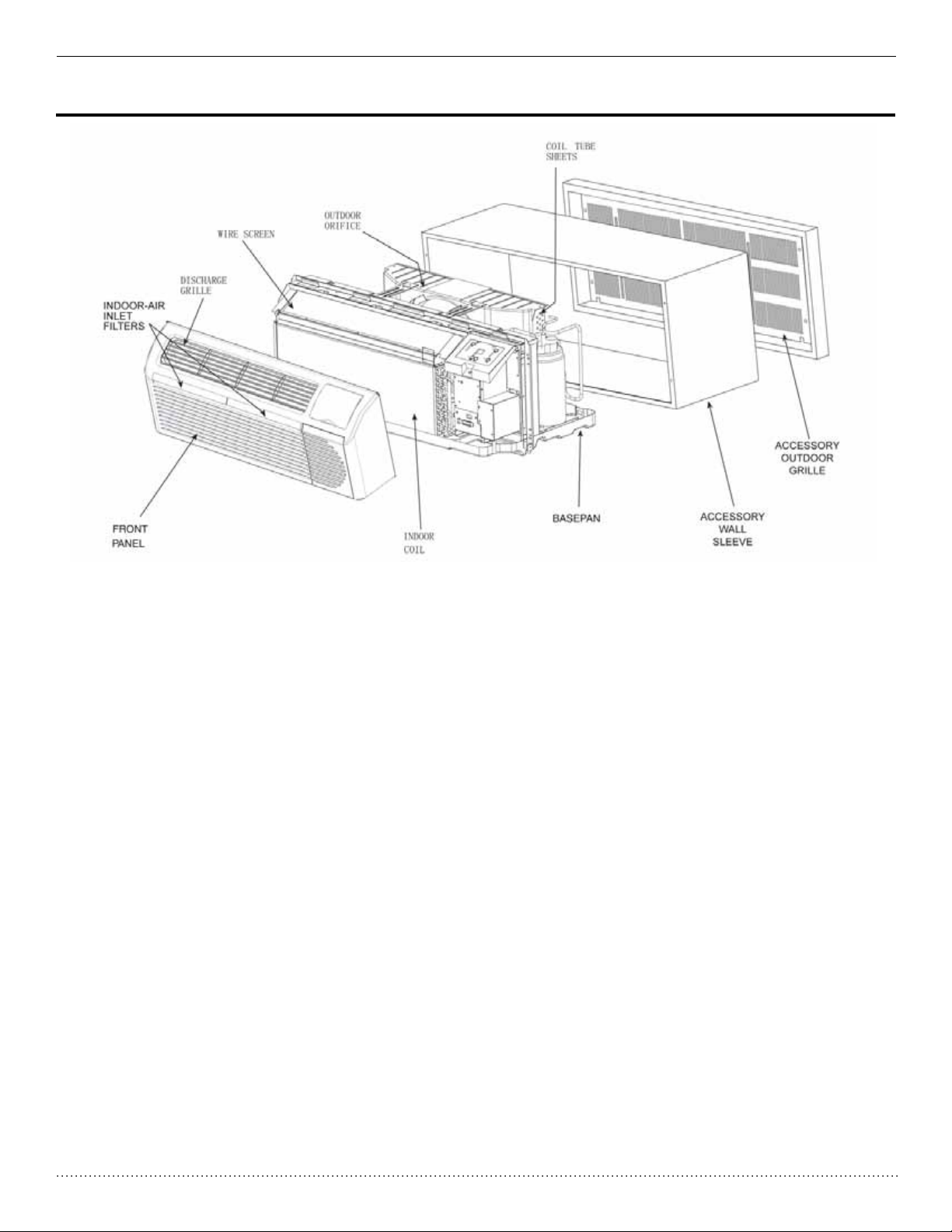
UNIT COMPONENTS
2
Page 4
PACKAGED TERMINAL A/C SERVICE MANUAL Heat Controller
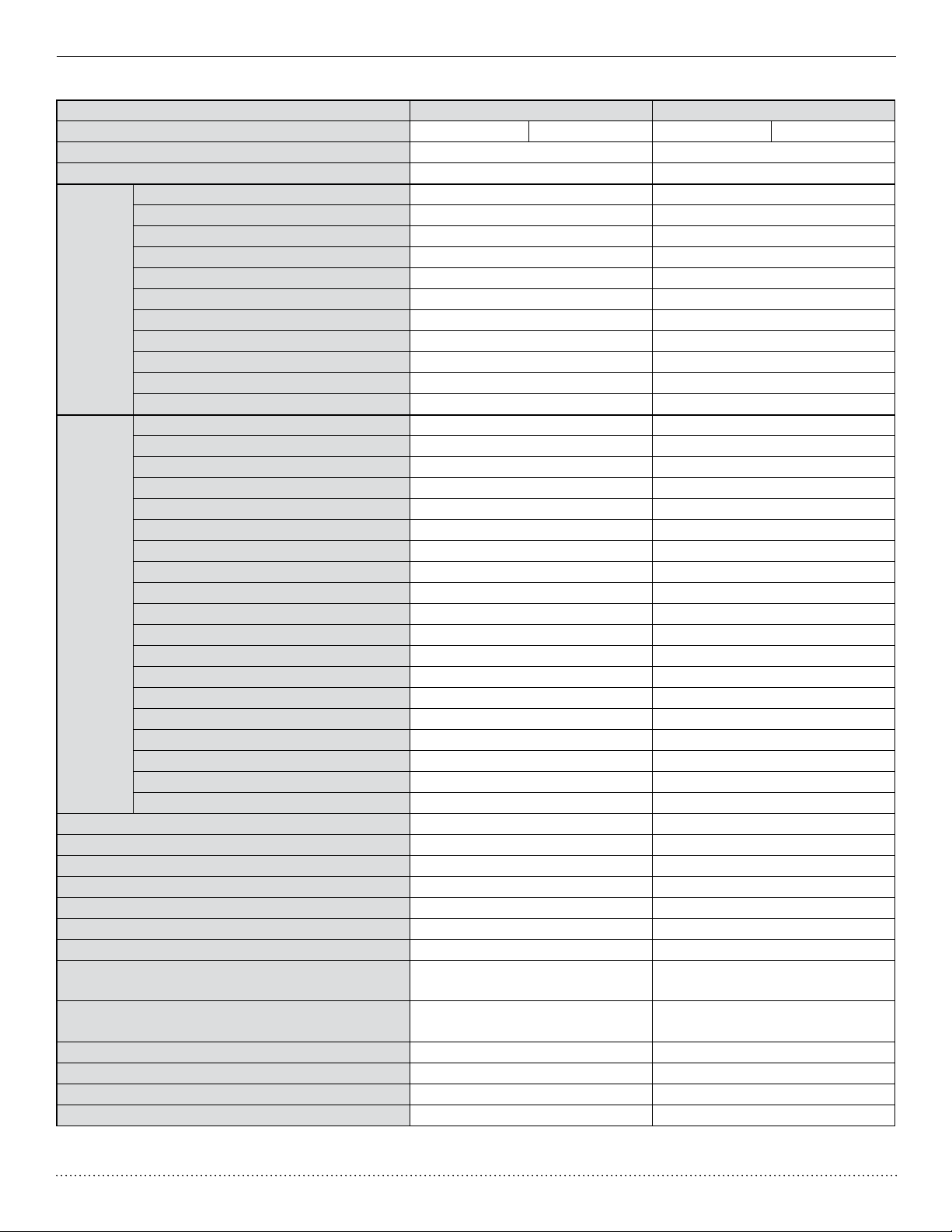
Specication and Technical Parameters
Model EKTC07-1G EKTH07-1G
Function Cooling Heating Cooling Heating
Rated Voltage 230/208V 230/208V
Rated Frequency 60Hz 60Hz
Fan Type-Piece Cross Flow Fan - 1 Cross Flow Fan - 1
Diameter-Length in. (mm) 4.75 x 27.795 (121 x 706) 4.75 x 27.795 (121 x 706)
Evaporator Aluminum n - Aluminum tube Aluminum n - Aluminum tube
Pipe Diameter in. (mm) 1/32” (7.94) 1/32” (7.94)
Indoor
Side
Outdoor
Side
Fan Motor Speed (rpm) (H/M/L) 1370 1370
Output of Fan Motor (W) 40 40
Fan Motor RLA (A) 0.35 0.35
Fan Motor Capacitor (uF) 2 2
Climate Type T1 T1
Isolation I I
Moisture Protection IP24 IP24
Permissible Excessive Operating Pressure
for the Discharge Side psi (MPa)
Permissible Excessive Operating Pressure
for the Suction Side psi (MPa)
Dimension (W/H/D) in. (mm) 42 x 16 x 21.5 (1069/406/546) 42 x 16 x 21.5 (1069/406/546)
Dimension of Package (L/W/H) in. (mm) 45 x 25.275 x 18.125 (1141/642/460) 45 x 25.275 x 18.125 (1141/642/460)
Net Weight/Gross Weight lbs. (kg) 99.2/19.05 (45/54) 99.2/19.05 (45/54)
Refrigerant Charge oz. (kg) R-410A 23.63 oz. (0.67) R-410A 23.63 oz. (0.67)
The above data is subject to change without notice. Please refer to the nameplate of the unit.
Row-Fin Gap in. (mm) 2-0.05” (2-1.4) 2-0.05” (2-1.4)
Coil Length x Height x Width in. (mm) 27.5 x 9.75 x 1” (698 x 248 x 25.4) 27.5 x 9.75 x 1” (698 x 248 x 25.4)
Swing Motor Model / /
Output of Swing Motor / /
Fuse (A) / /
Sound Pressure Level dB (A) (H/M/L) 48/46/44 48/46/44
Sound Power Level dB (A) (H/M/L) 58/56/54 58/56/54
Compressor Manufacturer/Trademark Panasonic Panasonic
Compressor Model 5RS062FAA21 5RS062FAA21
Compressor Type Rotary Rotary
L.R.A (A) 19 19
Compressor RLA (A) 2.85 2.85
Compressor Power Input (W) 640 640
Overload Protector B130-140-241E B130-140-241E
Throttling Method Capillary Capillary
Starting Method Capacitor Capacitor
Working Temperature Range °F (°C) 55.4-114.89°F (13-46°C) 55.4-114.89°F (13-46°C)
Condenser Aluminum Fin-Copper Tube Aluminum Fin-Copper Tube
Pipe Diameter in. (mm) 0.28” (7) 0.28” (7)
Rows-Fin Gap in. (mm) 2-0.05” (2-1.3) 2-0.05” (2-1.3)
Coil Length x Height x Width in. (mm) 25 x 13.5 x 1” (635 x 343 x 25.4) 25 x 13.5 x 1” (635 x 343 x 25.4)
Fan Type-Piece Axial Fan–1 Axial Fan–1
Fan Diameter in. (mm) 13.75” (349) 13.75” (349)
Sound Pressure Level dB (A) (H/M/L) 61/59/57 61/59/57
Sound Power Level dB (A) (H/M/L) 71/69/67 71/69/67
Defrosting Mode / /
580.15 (4) 580.15 (4)
304.58 (2.1) 304.58 (2.1)
3
Page 5
Heat Controller SERVICE MANUAL Packaged Terminal A/C
Model EKTC07-2G EKTH07-2G
Function Cooling Heating Cooling Heating
Rated Voltage 265V 265V
Rated Frequency 60Hz 60Hz
Fan Type-Piece Cross Flow Fan - 1 Cross Flow Fan - 1
Diameter-Length in. (mm) 4.75 x 27.295 (121 x 706) 4.75 x 27.295 (121 x 706)
Evaporator Aluminum n - Aluminum tube Aluminum n - Aluminum tube
Pipe Diameter in. (mm) 5/16” (7.94) 5/16” (7.94)
Indoor
Side
Outdoor
Side
Fan Motor Speed (rpm) (H/M/L) 1380 1380
Output of Fan Motor (W) 40 40
Fan Motor RLA (A) 0.3 0.3
Fan Motor Capacitor (uF) 1.5 1.5
Climate Type T1 T1
Isolation I I
Moisture Protection IP24 IP24
Permissible Excessive Operating Pressure
for the Discharge Side psi (MPa)
Permissible Excessive Operating Pressure
for the Suction Side psi (MPa)
Dimension (W/H/D) in. (mm) 42 x 16 x 21.5 (1069/406/546) 42 x 16 x 21.5 (1069/406/546)
Dimension of Package (L/W/H) in. (mm) 45 x 25.275 x 18.125 (1141/642/460) 45 x 25.275 x 18.125 (1141/642/460)
Net Weight/Gross Weight lbs. (kg) 119.05/138.89 (45/54) 119.05/138.89 (45/54)
Refrigerant Charge oz. (kg) R-410A 24.69 oz. (0.67) R-410A 24.69 oz. (0.67)
The above data is subject to change without notice. Please refer to the nameplate of the unit.
Row-Fin Gap in. (mm) 2-0.05” (2-1.4) 2-0.05” (2-1.4)
Coil Length x Height x Width in. (mm) 27.5 x 9.75 x 1” (698 x 248 x 25.4) 27.5 x 9.75 x 1” (698 x 248 x 25.4)
Swing Motor Model / /
Output of Swing Motor / /
Fuse (A) / /
Sound Pressure Level dB (A) (H/M/L) 48/46/44 48/46/44
Sound Power Level dB (A) (H/M/L) 58/56/54 58/56/54
Compressor Manufacturer/Trademark Panasonic Panasonic
Compressor Model 5RS062LAA1 5RS062LAA1
Compressor Type Rotary Rotary
L.R.A (A) 12 12
Compressor RLA (A) 2.45 2.45
Compressor Power Input (W) 645 645
Overload Protector B90-150-24E B90-150-24E
Throttling Method Capillary Capillary
Starting Method Capacitor Capacitor
Working Temperature Range °F (°C) 55.4-114.8°F (13-46°C) 55.4-114.8°F (13-46°C)
Condenser Aluminum Fin-Copper Tube Aluminum Fin-Copper Tube
Pipe Diameter in. (mm) 0.28” (7) 0.28” (7)
Rows-Fin Gap in. (mm) 0.05” (2-1.3) 0.05” (2-1.3)
Coil Length x Height x Width in. (mm) 25 x 13.5 x 1” (635 x 343 x 25.4) 25 x 13.5 x 1” (635 x 343 x 25.4)
Fan Type-Piece Axial Fan–1 Axial Fan–1
Fan Diameter in. (mm) 13.75” (349) 13.75” (349)
Sound Pressure Level dB (A) (H/M/L) 61/59/57 61/59/57
Sound Power Level dB (A) (H/M/L) 71/69/67 71/69/67
Defrosting Mode / /
580.15 (4) 580.15 (4)
304.58 (2.1) 304.58 (2.1)
4
Page 6
PACKAGED TERMINAL A/C SERVICE MANUAL Heat Controller
Model EKTC09-1G EKTH09-1G
Function Cooling Heating Cooling Heating
Rated Voltage 230/208V 230/208V
Rated Frequency 60Hz 60Hz
Fan Type-Piece Cross Flow Fan - 1 Cross Flow Fan - 1
Diameter-Length in. (mm) 4.75 x 27.795 (121 x 706) 4.75 x 27.795 (121 x 706)
Evaporator Aluminum Fin-Copper Tube Aluminum Fin-Copper Tube
Pipe Diameter in. (mm) 0.28” (7) 0.28” (7)
Indoor
Side
Outdoor
Side
Fan Motor Speed (rpm) (H/M/L) 1370 1370
Output of Fan Motor (W) 65 65
Fan Motor RLA (A) 0.6 0.6
Fan Motor Capacitor (uF) 2 2
Climate Type T1 T1
Isolation I I
Moisture Protection IP24 IP24
Permissible Excessive Operating Pressure
for the Discharge Side psi (MPa)
Permissible Excessive Operating Pressure
for the Suction Side psi (MPa)
Dimension (W/H/D) in. (mm) 42 x 16 x 21.5 (1069/406/546) 42 x 16 x 21.5 (1069/406/546)
Dimension of Package (L/W/H) in. (mm) 45 x 25.275 x 18.125 (1141/642/460) 45 x 25.275 x 18.125 (1141/642/460)
Net Weight/Gross Weight lbs. (kg) 119.05/138.85 (54/63) 119.05/138.85 (54/63)
Refrigerant Charge oz. (kg) R-410A 33.5 oz. (0.95) R-410A 33.5 oz. (0.95)
The above data is subject to change without notice. Please refer to the nameplate of the unit.
Row-Fin Gap in. (mm) 2-0.05” (2-1.4) 2-0.05” (2-1.4)
Coil Length x Height x Width in. (mm) 27.5 x 9.75 x 1” (698 x 248 x 25.4) 27.5 x 9.75 x 1” (698 x 248 x 25.4)
Swing Motor Model / /
Output of Swing Motor / /
Fuse (A) / /
Sound Pressure Level dB (A) (H/M/L) 50/48/46 50/48/46
Sound Power Level dB (A) (H/M/L) 60/58/56 60/58/56
Compressor Manufacturer/Trademark Mitsubish Samsung
Compressor Model KN073NGFMC G4C085IUBJP
Compressor Type Rotary Rotary
L.R.A (A) 17 18.5
Compressor RLA (A) 3.7 3.6
Compressor Power Input (W) 74 0 740
Overload Protector Interior Interior
Throttling Method Capillary Capillary
Starting Method Capacitor Capacitor
Working Temperature Range °F (°C) 64.4-109.4°F (18-43°C) 64.4-109.4°F (18-43°C)
Condenser Aluminum Fin-Copper Tube Aluminum Fin-Copper Tube
Pipe Diameter in. (mm) 0.28” (7) 0.28” (7)
Rows-Fin Gap in. (mm) 0.05” (3-1.4) 0.05” (3-1.4)
Coil Length x Height x Width in. (mm) 25 x 13.5 x 1” (635 x 343 x 25.4) 25 x 13.5 x 1” (635 x 343 x 25.4)
Fan Type-Piece Axial Fan–1 Axial Fan–1
Fan Diameter in. (mm) 13.75” (349) 13.75” (349)
Sound Pressure Level dB (A) (H/M/L) 61/59/57 61/59/57
Sound Power Level dB (A) (H/M/L) 71/69/67 71/69/67
Defrosting Mode / /
580.15 (4) 580.15 (4)
188.55 (1.3) 188.55 (1.3)
5
Page 7

Heat Controller SERVICE MANUAL Packaged Terminal A/C
Model EKTC09-2G EKTH09-2G
Function Cooling Heating Cooling Heating
Rated Voltage 265V 265V
Rated Frequency 60Hz 60Hz
Fan Type-Piece Cross Flow Fan - 1 Cross Flow Fan - 1
Diameter-Length in. (mm) 4.75 x 27.795 (121 x 706) 4.75 x 27.795 (121 x 706)
Evaporator Aluminum Fin-Copper Tube Aluminum Fin-Copper Tube
Pipe Diameter in. (mm) 0.28” (7) 0.28” (7)
Indoor
Side
Outdoor
Side
Fan Motor Speed (rpm) (H/M/L) 1540 1540
Output of Fan Motor (W) 45 45
Fan Motor RLA (A) 0.35 0.35
Fan Motor Capacitor (uF) 1.5 1.5
Climate Type T1 T1
Isolation I I
Moisture Protection IP24 IP24
Permissible Excessive Operating Pressure
for the Discharge Side psi (MPa)
Permissible Excessive Operating Pressure
for the Suction Side psi (MPa)
Dimension (W/H/D) in. (mm) 42 x 16 x 21.5 (1069/406/546) 42 x 16 x 21.5 (1069/406/546)
Dimension of Package (L/W/H) in. (mm) 45 x 25.275 x 18.125 (1141/642/460) 45 x 25.275 x 18.125 (1141/642/460)
Net Weight/Gross Weight lbs. (kg) 110.23/131.8 (50.5/59.5) 113.54/133/38 (51.5/60.5)
Refrigerant Charge oz. (kg) R-410A 33.5 oz. (0.95) R-410A 35.27 oz. (1.0)
The above data is subject to change without notice. Please refer to the nameplate of the unit.
Row-Fin Gap in. (mm) 0.05” (2-1.4) 0.05” (2-1.4)
Coil Length x Height x Width in. (mm) 27.5 x 9.75 x 1” (698 x 248 x 25.4) 27.5 x 9.75 x 1” (698 x 248 x 25.4)
Swing Motor Model / /
Output of Swing Motor / /
Fuse (A) / /
Sound Pressure Level dB (A) (H/M/L) 50/48/46 50/48/46
Sound Power Level dB (A) (H/M/L) 60/58/56 60/58/56
Compressor Manufacturer/Trademark Panasonic Samsung
Compressor Model 5RS072LAA21 G4C085YUAJP
Compressor Type Rotary Rotary
L.R.A (A) 15 19
Compressor RLA (A) 2.9 3.2
Compressor Power Input (W) 750 795
Overload Protector Interior Interior
Throttling Method Capillary Capillary
Starting Method Capacitor Capacitor
Working Temperature Range °F (°C) 64.4-109.4°F (18-43°C) 64.4-109.4°F (18-43°C)
Condenser Aluminum Fin-Copper Tube Aluminum Fin-Copper Tube
Pipe Diameter in. (mm) 0.28” (7) 0.28” (7)
Rows-Fin Gap in. (mm) 0.05” (3-1.4) 0.05” (3-1.4)
Coil Length x Height x Width in. (mm) 25 x 13.5 x 1” (635 x 343 x 25.4) 25 x 13.5 x 1” (635 x 343 x 25.4)
Fan Type-Piece Axial Fan–1 Axial Fan–1
Fan Diameter in. (mm) 13.75” (349) 13.75” (349)
Sound Pressure Level dB (A) (H/M/L) 61/59/57 61/59/57
Sound Power Level dB (A) (H/M/L) 71/69/67 71/69/67
Defrosting Mode / /
580.15 (4) 580.15 (4)
188.55 (1.3) 188.55 (1.3)
6
Page 8

PACKAGED TERMINAL A/C SERVICE MANUAL Heat Controller
Model EKTC12-1G EKTH12-1G
Function Cooling Heating Cooling Heating
Rated Voltage 230/208V 230/208V
Rated Frequency 60Hz 60Hz
Fan Type-Piece Cross Flow Fan - 1 Cross Flow Fan - 1
Diameter-Length in. (mm) 4.75 x 27.795 (121 x 706) 4.75 x 27.795 (121 x 706)
Evaporator Aluminum Fin-Copper Tube Aluminum Fin-Copper Tube
Pipe Diameter in. (mm) 0.28” (7) 0.28” (7)
Indoor
Side
Outdoor
Side
Fan Motor Speed (rpm) (H/M/L) 1370 1370
Output of Fan Motor (W) 65 65
Fan Motor RLA (A) 0.6 0.6
Fan Motor Capacitor (uF) 1.5 1.5
Climate Type T1 T1
Isolation I I
Moisture Protection IP24 IP24
Permissible Excessive Operating Pressure
for the Discharge Side psi (MPa)
Permissible Excessive Operating Pressure
for the Suction Side psi (MPa)
Dimension (W/H/D) in. (mm) 42 x 16 x 21.5 (1069/406/546) 42 x 16 x 21.5 (1069/406/546)
Dimension of Package (L/W/H) in. (mm) 45 x 25.275 x 18.125 (1141/642/460) 45 x 25.275 x 18.125 (1141/642/460)
Net Weight/Gross Weight lbs. (kg) 119.05/138.89 (54/63) 119.05/138.89 (54/63)
Refrigerant Charge oz. (kg) R-410A 35.27 oz. (1.0) R-410A 35.27 oz. (1.0)
The above data is subject to change without notice. Please refer to the nameplate of the unit.
Row-Fin Gap in. (mm) 2-0.05” (2-1.4) 2-0.05” (2-1.4)
Coil Length x Height x Width in. (mm) 27.5 x 9.75 x 1.5” (698 x 248 x 25.4) 27.5 x 9.75 x 1.5” (698 x 248 x 25.4)
Swing Motor Model / /
Output of Swing Motor / /
Fuse (A) / /
Sound Pressure Level dB (A) (H/M/L) 52/50/48 52/50/48
Sound Power Level dB (A) (H/M/L) 62/60/58 62/60/58
Compressor Manufacturer/Trademark Samsung Samsung
Compressor Model G4A110IUBJP G4A110IUBJP
Compressor Type Rotary Rotary
L.R.A (A) 27 27
Compressor RLA (A) 5 5
Compressor Power Input (W) 1095 1095
Overload Protector Interior Interior
Throttling Method Capillary Capillary
Starting Method Capacitor Capacitor
Working Temperature Range °F (°C) 64.4-109.4°F (18-43°C) 64.4-109.4°F (18-43°C)
Condenser Aluminum Fin-Copper Tube Aluminum Fin-Copper Tube
Pipe Diameter in. (mm) 0.28” (7) 0.28” (7)
Rows-Fin Gap in. (mm) 0.05” (3-1.4) 0.05” (3-1.4)
Coil Length x Height x Width in. (mm) 25 x 13.5 x 1.5” (635 x 343 x 25.4) 25 x 13.5 x 1.5” (635 x 343 x 25.4)
Fan Type-Piece Axial Fan–1 Axial Fan–1
Fan Diameter in. (mm) 13.75” (349) 13.75” (349)
Sound Pressure Level dB (A) (H/M/L) 63/61/59 63/61/59
Sound Power Level dB (A) (H/M/L) 73/71/69 73/71/69
Defrosting Mode / /
580.15 (4) 580.15 (4)
188.55 (1.3) 188.55 (1.3)
7
Page 9
Heat Controller SERVICE MANUAL Packaged Terminal A/C
Model EKTC12-2G EKTH12-2G
Function Cooling Heating Cooling Heating
Rated Voltage 265V 265V
Rated Frequency 60Hz 60Hz
Fan Type-Piece Cross Flow Fan - 1 Cross Flow Fan - 1
Diameter-Length in. (mm) 4.75 x 27.795 (121 x 706) 4.75 x 27.795 (121 x 706)
Evaporator Aluminum Fin-Copper Tube Aluminum Fin-Copper Tube
Pipe Diameter in. (mm) 0.28” (7) 0.28” (7)
Indoor
Side
Outdoor
Side
Fan Motor Speed (rpm) (H/M/L) 1540 1540
Output of Fan Motor (W) 45 45
Fan Motor RLA (A) 0.35 0.35
Fan Motor Capacitor (uF) 1.5 1.5
Climate Type T1 T1
Isolation I I
Moisture Protection IP24 IP24
Permissible Excessive Operating Pressure
for the Discharge Side psi (MPa)
Permissible Excessive Operating Pressure
for the Suction Side psi (MPa)
Dimension (W/H/D) in. (mm) 42 x 16 x 21.5 (1069/406/546) 42 x 16 x 21.5 (1069/406/546)
Dimension of Package (L/W/H) in. (mm) 45 x 25.275 x 18.125 (1141/642/460) 45 x 25.275 x 18.125 (1141/642/460)
Net Weight/Gross Weight lbs. (kg) 119.05/138.84 (54/63) 119.05/138.84 (54/63)
Refrigerant Charge oz. (kg) R-410A 35.98 oz. (1.02) R-410A 35.98 oz. (1.02)
The above data is subject to change without notice. Please refer to the nameplate of the unit.
Row-Fin Gap in. (mm) 2-0.05” (2-1.4) 2-0.05” (2-1.4)
Coil Length x Height x Width in. (mm) 27.5 x 9.75 x 1.5” (698 x 248 x 25.4) 27.5 x 9.75 x 1.5” (698 x 248 x 25.4)
Swing Motor Model / /
Output of Swing Motor / /
Fuse (A) / /
Sound Pressure Level dB (A) (H/M/L) 52/50/48 52/50/48
Sound Power Level dB (A) (H/M/L) 62/60/58 62/60/58
Compressor Manufacturer/Trademark Samsung Samsung
Compressor Model G4A110YUAJP G4A110YUAJP
Compressor Type Rotary Rotary
L.R.A (A) 23 23
Compressor RLA (A) 4.3 4.3
Compressor Power Input (W) 1090 1090
Overload Protector Interior Interior
Throttling Method Capillary Capillary
Starting Method Capacitor Capacitor
Working Temperature Range °F (°C) 64.4-109.4°F (18-43°C) 64.4-109.4°F (18-43°C)
Condenser Aluminum Fin-Copper Tube Aluminum Fin-Copper Tube
Pipe Diameter in. (mm) 0.28” (7) 0.28” (7)
Rows-Fin Gap in. (mm) 0.05” (3-1.4) 0.05” (3-1.4)
Coil Length x Height x Width in. (mm) 25 x 13.5 x 1.5” (635 x 343 x 25.4) 25 x 13.5 x 1.5” (635 x 343 x 25.4)
Fan Type-Piece Axial Fan–1 Axial Fan–1
Fan Diameter in. (mm) 13.75” (349) 13.75” (349)
Sound Pressure Level dB (A) (H/M/L) 63/61/59 63/61/59
Sound Power Level dB (A) (H/M/L) 73/71/69 73/71/69
Defrosting Mode / /
580.13 (4) 580.13 (4)
188.55 (1.3) 188.55 (1.3)
8
Page 10

PACKAGED TERMINAL A/C SERVICE MANUAL Heat Controller
Model EKTC15-1G EKTH15-1G
Function Cooling Heating Cooling Heating
Rated Voltage 230/208V 230/208V
Rated Frequency 60Hz 60Hz
Fan Type-Piece Cross Flow Fan - 1 Cross Flow Fan - 1
Diameter-Length in. (mm) 4.75 x 27.795 (121 x 706) 4.75 x 27.795 (121 x 706)
Evaporator Aluminum Fin-Copper Tube Aluminum Fin-Copper Tube
Pipe Diameter in. (mm) 0.28” (7) 0.28” (7)
Indoor
Side
Outdoor
Side
Fan Motor Speed (rpm) (H/M/L) 1370 1600
Output of Fan Motor (W) 65 65
Fan Motor RLA (A) 0.6 0.6
Fan Motor Capacitor (uF) 2.5 2.5
Climate Type T1 T1
Isolation I I
Moisture Protection IP24 IP24
Permissible Excessive Operating Pressure
for the Discharge Side psi (MPa)
Permissible Excessive Operating Pressure
for the Suction Side psi (MPa)
Dimension (W/H/D) in. (mm) 42 x 16 x 21.5 (1069/406/546) 42 x 16 x 21.5 (1069/406/546)
Dimension of Package (L/W/H) in. (mm) 45 x 25.275 x 18.125 (1141/642/460) 45 x 25.275 x 18.125 (1141/642/460)
Net Weight/Gross Weight lbs. (kg) 119.05/138.84 (54/63) 119.05/138.84 (54/63)
Refrigerant Charge oz. (kg) R-410A 38.01 oz. (1.08) R-410A 38.01 oz. (1.08)
The above data is subject to change without notice. Please refer to the nameplate of the unit.
Row-Fin Gap in. (mm) 2-0.05” (2-1.4) 2-0.05” (2-1.4)
Coil Length x Height x Width in. (mm) 27.5 x 9.75 x 1.5” (698 x 248 x 25.4) 27.5 x 9.75 x 1.5” (698 x 248 x 25.4)
Swing Motor Model / /
Output of Swing Motor / /
Fuse (A) / /
Sound Pressure Level dB (A) (H/M/L) 52/48/46 52/48/46
Sound Power Level dB (A) (H/M/L) 62/58/56 62/58/56
Compressor Manufacturer/Trademark Panasonic Panasonic
Compressor Model 5PS146FAA21 5PS146FAA21
Compressor Type Rotary Rotary
L.R.A (A) 32.6 32.6
Compressor RLA (A) 6.6 6.6
Compressor Power Input (W) 1485 1485
Overload Protector B205-150-141C B205-150-141C
Throttling Method Capillary Capillary
Starting Method Capacitor Capacitor
Working Temperature Range °F (°C) 55.4-114.8°F (13-46°C) 55.4-114.8°F (13-46°C)
Condenser Aluminum Fin-Copper Tube Aluminum Fin-Copper Tube
Pipe Diameter in. (mm) 0.31” (8) 0.31” (8)
Rows-Fin Gap in. (mm) 0.05” (3-1.4) 0.05” (3-1.4)
Coil Length x Height x Width in. (mm) 25 x 13.85 x 2.25” (635 x 352 x 57.2) 25 x 13.85 x 2.25” (635 x 352 x 57.2)
Fan Type-Piece Axial Fan–1 Axial Fan–1
Fan Diameter in. (mm) 13.75” (349) 13.75” (349)
Sound Pressure Level dB (A) (H/M/L) 65/61/59 65/61/59
Sound Power Level dB (A) (H/M/L) 75/71/69 75/71/69
Defrosting Mode / /
580.15 (4) 580.15 (4)
188.15 (1.3) 188.15 (1.3)
9
Page 11
Heat Controller SERVICE MANUAL Packaged Terminal A/C
Model EKTC15-2G EKTH15-2G
Function Cooling Heating Cooling Heating
Rated Voltage 265V 265V
Rated Frequency 60Hz 60Hz
Fan Type-Piece Cross Flow Fan - 1 Cross Flow Fan - 1
Diameter-Length in. (mm) 4.75 x 27.795 (121 x 706) 4.75 x 27.795 (121 x 706)
Evaporator Aluminum Fin-Copper Tube Aluminum Fin-Copper Tube
Pipe Diameter in. (mm) 0.28” (7) 0.28” (7)
Indoor
Side
Outdoor
Side
Fan Motor Speed (rpm) (H/M/L) 1540 1540
Output of Fan Motor (W) 45 45
Fan Motor RLA (A) 0.35 0.35
Fan Motor Capacitor (uF) 2.5 2.5
Climate Type T1 T1
Isolation I I
Moisture Protection IP24 IP24
Permissible Excessive Operating Pressure
for the Discharge Side psi (MPa)
Permissible Excessive Operating Pressure
for the Suction Side psi (MPa)
Dimension (W/H/D) in. (mm) 42 x 16 x 21.5 (1069/406/546) 42 x 16 x 21.5 (1069/406/546)
Dimension of Package (L/W/H) in. (mm) 45 x 25.275 x 18.125 (1141/642/460) 45 x 25.275 x 18.125 (1141/642/460)
Net Weight/Gross Weight lbs. (kg) 119.05/138.84 (54/63) 119.05/138.84 (54/63)
Refrigerant Charge oz. (kg) R-410A 40.21 oz. (1.14) R-410A 40.21 oz. (1.14)
The above data is subject to change without notice. Please refer to the nameplate of the unit.
Row-Fin Gap in. (mm) 2-0.05” (2-1.4) 2-0.05” (2-1.4)
Coil Length x Height x Width in. (mm) 27.5 x 9.75 x 1.5” (698 x 248 x 25.4) 27.5 x 9.75 x 1.5” (698 x 248 x 25.4)
Swing Motor Model / /
Output of Swing Motor / /
Fuse (A) / /
Sound Pressure Level dB (A) (H/M/L) 52/48/46 52/48/46
Sound Power Level dB (A) (H/M/L) 62/58/56 62/58/56
Compressor Manufacturer/Trademark Panasonic Panasonic
Compressor Model 5PS146LAA21 5PS146LAA21
Compressor Type Rotary Rotary
L.R.A (A) 32.6 32.6
Compressor RLA (A) 6.6 6.6
Compressor Power Input (W) 1475 1475
Overload Protector B180-150-141E B180-150-141E
Throttling Method Capillary Capillary
Starting Method Capacitor Capacitor
Working Temperature Range °F (°C) 55.4-114.8°F (13-46°C) 55.4-114.8°F (13-46°C)
Condenser Aluminum Fin-Copper Tube Aluminum Fin-Copper Tube
Pipe Diameter in. (mm) 0.31” (8) 0.31” (8)
Rows-Fin Gap in. (mm) 0.05” (3-1.4) 0.05” (3-1.4)
Coil Length x Height x Width in. (mm) 25 x 13.85 x 2.25” (635 x 352 x 57.2) 25 x 13.85 x 2.25” (635 x 352 x 57.2)
Fan Type-Piece Axial Fan–1 Axial Fan–1
Fan Diameter in. (mm) 13.75” (349) 13.75” (349)
Sound Pressure Level dB (A) (H/M/L) 65/61/59 65/61/59
Sound Power Level dB (A) (H/M/L) 75/71/69 75/71/69
Defrosting Mode / /
580.15 (4) 580.15 (4)
188.55 (1.3) 188.55 (1.3)
10
Page 12

PACKAGED TERMINAL A/C SERVICE MANUAL Heat Controller
EXTENDED PERFORMANCE DATA
EXTENDED COOLING PERFORMANCE
OUTDOOR DRY BULB TEMP. (DEGREES F AT 40% R.H.)
75 85 95 105 110
INDOOR WET BULB TEMP. (DEGREES F AT 80 F D.B.)
72 67 62 72 67 62 72 67 62 72 67 62 72 67 62
9055 8709 8062 8624 8131 7500 8285 7700 6815 7762 6892 6076 6907 5944 5251
522 530 536 569 575 582 640 640 640 691 691 693 755 755 758
2.5 2.5 2.6 2.7 2.8 2.8 3 3 3 3.3 3.3 3.3 3.6 3.6 3.6
SHR
SHR
SHR
SHR
0.58 0.79 0.95 0.59 0.81 0.99 0.59 0.84 0.99 0.6 0.88 0.99 0.63 0.95 0.99
10584 10179 9423 10080 9504 8766 9684 9000 7965 9072 8055 7101 8073 6948 6138
653 663 670 711 719 727 800 800 800 865 864 866 943 943 947
3.3 3.3 3.3 3.5 3.5 3.5 3.9 3.9 3.9 4.2 4.2 4.2 4.6 4.6 4.6
0.56 0.75 0.91 0.57 0.79 0.92 0.57 0.81 0.92 0.58 0.86 0.94 0.62 0.91 0.92
14112 13573 12565 13440 12672 11688 12912 12000 10621 12096 10741 9469 10765 9264 8184
914 928 938 996 1006 1018 1120 1120 1120 1210 1209 1213 1321 1321 1326
4.4 4.4 4.4 4.7 4.7 4.8 5.3 5.3 5.3 5.7 5.7 5.7 6.3 6.3 6.3
0.46 0.62 0.84 0.47 0.65 0.86 0.47 0.67 0.86 0.48 0.71 0.87 0.51 0.75 0.86
17640 16965 15705 16800 15840 14610 16140 15000 13275 15120 13425 11835 13455 11580 10230
1248 1269 1282 1360 1373 1391 1530 1530 1530 1654 1652 1657 1803 1803 1812
6.2 6.2 6.3 6.6 6.8 6.8 7.5 7.5 7.5 8.0 8.0 8.1 8.8 8.8 8.8
0.45 0.60 0.81 0.46 0.63 0.83 0.46 0.65 0.83 0.47 0.69 0.84 0.49 0.74 0.83
RATING POINT
ARI 310/380
EKTC07
EKTC09
EKTC12
EKTC15
BTUh
WATTS
AMPS
BTUh
WATTS
AMPS
BTUh
WATTS
AMPS
BTUh
WATTS
AMPS
EKTH07
EKTH09
EKTH12
EKTH15
BTUh
WATTS
AMPS
SHR
BTUh
WATTS
AMPS
SHR
BTUh
WATTS
AMPS
SHR
BTUh
WATTS
AMPS
SHR
EXTENDED COOLING PERFORMANCE
OUTDOOR DRY BULB TEMP. (DEGREES F AT 40% R.H.)
75 85 95 105 110
INDOOR WET BULB TEMP. (DEGREES F AT 80 F D.B.)
72 67 62 72 67 62 72 67 62 72 67 62 72 67 62
9055 8709 8062 8624 8131 7500 8285 7700 6815 7762 6892 6076 6907 5944 5251
522 530 536 569 575 582 640 640 640 691 691 693 755 755 758
2.5 2.5 2.6 2.7 2.8 2.8 3 3 3 3.3 3.3 3.3 3.6 3.6 3.6
0.58 0.79 0.95 0.59 0.81 0.99 0.59 0.84 0.99 0.6 0.88 0.99 0.63 0.95 0.99
10584 10179 9423 10080 9504 8766 9684 9000 7965 9072 8055 7101 8073 6948 6138
653 663 670 711 719 727 800 800 800 865 864 866 943 943 947
3.3 3.3 3.3 3.5 3.5 3.5 3.9 3.9 3.9 4.2 4.2 4.2 4.6 4.6 4.6
0.56 0.75 0.91 0.57 0.79 0.92 0.57 0.81 0.92 0.58 0.86 0.94 0.62 0.91 0.92
14112 13573 12565 13440 12672 11688 12912 12000 10621 12096 10741 9469 10765 9264 8184
914 928 938 996 1006 1018 1120 1120 1120 1210 1209 1213 1321 1321 1326
4.4 4.4 4.4 4.7 4.7 4.8 5.3 5.3 5.3 5.7 5.7 5.7 6.3 6.3 6.3
0.46 0.62 0.84 0.47 0.65 0.86 0.47 0.67 0.86 0.48 0.71 0.87 0.51 0.75 0.86
17640 16965 15705 16800 15840 14610 16140 15000 13275 15120 13425 11835 13455 11580 10230
1248 1269 1282 1360 1373 1391 1530 1530 1530 1654 1652 1657 1803 1803 1812
6.2 6.2 6.3 6.6 6.8 6.8 7.5 7.5 7.5 8.0 8.0 8.1 8.8 8.8 8.8
0.45 0.60 0.81 0.46 0.63 0.83 0.46 0.65 0.83 0.47 0.69 0.84 0.49 0.74 0.83
RATING POINT
ARI 310/380
11
Page 13

Heat Controller SERVICE MANUAL Packaged Terminal A/C
EXTENDED PERFORMANCE DATA CONTINUED
EXTENDED HEATING PERFORMANCE
OUTDOOR DRY BULB TEMP. (DEGREES
37 42 47 52 57
BTUh 5250 5540 6300 6899 7620
F)
EKTH07
EKTH09
EKTH12
EKTH15
WATTS 509 518 540 549 580
AMPS 2.4 2.5 2.5 2.6 2.7
BTUh 6004 6399 8100 8647 9244
WATTS 646 656 720 725 735
AMPS 3.5 3.5 3.6 3.6 3.7
BTUh 7726 8531 10700 11278 12235
WATTS 883 917 1010 1040 1073
AMPS 4.2 4.3 4.7 4.9 5.1
BTUh 10926 11258 13800 15097 16540
WATTS 1280 1297 1390 1472 1539
AMPS 6.0 6.1 6.6 6.9 7.2
RATING POINT
ARI 310/380
12
Page 14

PACKAGED TERMINAL A/C SERVICE MANUAL Heat Controller
Controller Functions and Operating Methods
The relationship between Centigrade and Fahrenheit is: Tcentigrade=Tfahrenheit*1.8+3.2
A. Temperature Parameter
n Indoor setting temperature (Tpeset)
n Indoor ambient temperature (Tamb)
B. System Basic Function
The compressor has a 3 minute time delay before it will start as a protective feature. Once the compressor begins to run, the
compressor cannot be stopped by changing the set temperature. However, it can be stopped by changing the mode the unit is
operating in or by turning the unit off. Once the unit is restarted, the compressor will not restart until the 3 minute time delay
has surpassed. (The compressor can be stopped immediately at the time of mode switchover, turning off the unit, adjusting setting temperature and when in protective modes.)
1. Cooling Mode
When Tamb ≥Tpreset+2°F (1°C), the unit runs in cooling mode. Meanwhile, the compressor runs and the fan runs at the preset
fan speed.
When Tamb≤Tpreset-2°F (1°), the unit will turn OFF, the compressor will stop, however the fan will continue to run at the preset
fan speed;
When Tpreset-2°F (1°C)<Tamb<Tpreset+2°F (1°C), the unit keeps running with the previous settings.
n In this mode, the unit’s display will read the set temperature and the cooling LED is illuminated.
2. Fan Mode
In this mode, only the fan runs. The compressor won’t run and the temperature can’t be adjusted. The fan speed can be
changed. The display will read ambient temperature (32~99°F, when ambient temperature is higher than 99°F, it will display
H1; when ambient temperature is lower than 32°F, it will display L0), and the fan LED is illuminated.
3. Energy Saving Mode
When Tamb≥Tpreset+2°F (1°C), the unit runs in cooling mode. Meanwhile, the compressor runs and the fan runs at the preset
fan speed.
When Tamb≤Tpreset-2°F (1°C), the compressor will turn off while the fan will continue to run for 3 minutes; If Tamb≤Tpreset2°F (1°C), the fan will stop for 10 mins, and then turn on for 2 minutes at the preset speed. It will continue to cycle the fan on
and off in this sequence until Tamb≥Tpreset+2°F (1°C), then the fan and the compressor will start up (the start-up of compressor will be delayed for 3 minutes; the fan start up will occur 30 seconds prior to the compressor).
4. Heating Mode
When Tamb≤Tpresent-2°F (1°C), the unit is runs in heating mode. Meanwhile, the electric heater will start after the fan
runs for 3 seconds. When Tamb≥Tpresent+2°F (1°C), the electric heater will turn off and the fan will continue to run til Tair
exhaust≤90°F and the unit stops (the fan will run 15 seconds after the unit stops); Then the fan will stop for 10 minutes and
run for 1 minute at low fan speed. It will continue to cycle the fan on and off in this sequence until Tamb≤Tpreset-2°F (1°C).
5. OFF mode
If the OFF mode is selected the power button is active on the control panel. The freeze protection feature remains enabled, even
when the unit is OFF.
If the UP or DOWN buttons are pressed the display will turn off, after the ambient temperature is displayed for 15 seconds. The
indoor light will also turn off after 15 seconds.
6. Freeze Protection
This feature works in OFF, cooling and fan modes.
If the indoor ambient temperature is lower than 40°F (5°C) for 5 seconds, the electric heat mode and the freeze protection
mode will start up.
When the indoor ambient temperature is more than 50°F (10°C), the freeze protection mode will turn off.
After entering into the freeze protection mode, it can’t be stopped by pressing any buttons. During freeze protection mode, the
display reads “FP” and the green running LED is illuminated. During the freeze protection mode, the unit can’t be controlled by
the wall thermostat.
13
Page 15
Heat Controller SERVICE MANUAL Packaged Terminal A/C
Controller Function and Operating Method continued
7. Open circuit and short circuit of temperature sensor
If the temperature sensor has an open circuit, it will send an error signal. The error signal is displayed (see table below). If
malfunction of temperature sensor is detected, all the loads except the indoor fan will be turned off in cooling and fan mode;
However, in heating mode, all the loads will stop immediately and the indoor fan will blow off any residual heat for 6 seconds.
When the temperature sensor has malfunctioned and the fan has stopped, the fan can’t be restarted. In cooling and fan mode,
the fan will run normally. If the malfunction of the temperature senor occurs during the time of blowing residual heat, the fan will
stop after 1 minute.
C. Button and Displays
1. Buttons
Ther are ve buttons in all, ON/STOP, UP, DOWN, MODE and FAN SPEED.
1. In the OFF mode, press the ON/STOP button to turn on the unit: In OFF mode, if the UP or DOWN button is pressed, the display will turn off after displaying in the indoor temperature for 15 seconds; If the MODE button is pressed in the OFF mode,
the controller will resume to the running status before the unit was turned off. The green running LED is illuminated.
2. In ON mode
ON/STOP: After pressing the ON/STOP button, the unit can be switched between ON and OFF mode
MODE: In ON mode, after pressing the MODE button, the unit be switched between cooling, fan and heating modes; In
the OFF mode, after pressing the MODE button, the controller will run at the running status before turning off the unit.
FAN SPEED: In ON mode, after pressing the FAN SPEED button, you can select the high, medium and low fan speed.
UP, DOWN: Adjust the set temperature 61-86°F (16~30°C) by pressing the UP and DOWN buttons. Set temperature
ranges can be specied through conguration of the dip switches.
2. Display and LED Display
1. Mode LED display: when the A/C is runing, the corresponding LED is illuminated.
2. Running/power LED: In ON mode, the LED is green in color; In STOP status, the controller is red in color.
3. Fan speed display: When the A/C is running on high, medium and low fan speed, the corresponding LED is illuminated.
4. Display: In cooling and heating modes, the display shows the set temperature (in fan mode it displays the indoor ambi-
ent temperature).
5. Malfunction Display: After energization, when there’s malfunction or protective feature operating the STATUS LED will
blink to display an error code continuously. The error codes are shown below: Priority is decreasing from 1 to 8. In OFF
mode, the display will not show the error code (except for freeze protection). When multiple errors occur, the unit dis-
plays only the protection with the highest priority.
1 Indoor ambient temp sensor is open circuit/short circuit Display reads “F1” and STATUS LED blinks once and turns off for 3 seconds
2 Indoor tube temp sensor is open circuit and short circuit Display reads “F2” and STATUS LED blinks twice and turns off for 3 seconds
3 Outdoor tube temp sensor is open circuit and short circuit Display reads “F3” and STATUS LED blinks 4 times and turns off for 3 seconds
4 Low temperature resistant protection Display reads “FP”
5 Wrong wire connection for wall thermostat STATUS LED blinks 9 times and turns off for 3 seconds
6 High temperature resistant protection for evaporator STATUS LED blinks 8 times and turns off for 3 seconds
7 High temperature resistant protection for outdoor condenser STATUS LED blinks 6 times and turns off for 3 seconds
8 Antifreezing protection for evaporator STATUS LED blinks 5 times and turns off for 3 seconds
9 Frost protection (heat pump) STATUS LED blinks 7 times and turns off for 3 seconds
14
Page 16

PACKAGED TERMINAL A/C SERVICE MANUAL Heat Controller
D. Special Functions and Features
The PTAC unit is designed to be operated by the unit’s main control panel, however, factory installed connections are included to
allow the PTAC to operate via remote thermostat or energy management input (front desk control).
Energy Management Input
15
Page 17

Heat Controller SERVICE MANUAL Packaged Terminal A/C
SUGGESTIONS:
1. To size transformer, use the following equation:
Quantity of PTAC units x 12 va=Transformer Size (va)
Example: 110 PTAC units x 12 va = 1320 vaTransformer
2. Following are American Wire Gauge recommended sizes:
AWG WIRE SIZE NO. MAXIMUM LENGTH (ft)
24 400
22 600
20 900
18 1500
16 2000
16
Page 18
PACKAGED TERMINAL A/C SERVICE MANUAL Heat Controller
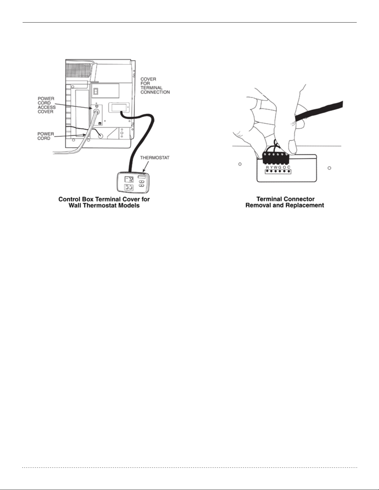
Wall Thermostat Connections
A standard low voltage wall thermostat can be wed with the PTAC unit’s factory installed terminal. Multiple PTACs can even be
connected together on a single wall thermostat.
17
Page 19

Heat Controller SERVICE MANUAL Packaged Terminal A/C
Typical Wiring Diagram
18
Page 20

PACKAGED TERMINAL A/C SERVICE MANUAL Heat Controller
E. Unit controls
The PTAC can be congured by the display and a set of dip switches.
1. TEMP CONTROL
Temp Control is used to maintain room temperature. Compressor will cycle on and off to keep room at the
requested level of comfort.
COOLER—Lowers temperature. (Minimum temperature setting is 61°F/16°C)
WARMER—Raises temperature. (Maximum temperature setting is 86°F/30°C)
2. FAN SPEED, MODE & ON/OFF
FAN SPEED—Set fan operation for HI, MED, or LO speed.
MODE-COOL—For cooling
MODE-HEAT—For heating
NOTE: If unit is a heat pump, raising the heat setting by 5°F will cause unit to use its electric heating elements for one
cycle in order to reach the new requested temperature quickly.
MODE-FAN—For fan--only operation
ON/OFF—Turns the unit on or off.
NOTE: The LED above the ON/OFF button will be green when unit is ON and red when the unit is OFF. All other
LEDs will be off when unit is set to OFF mode.
NOTE: Power remains connected to unit even when the unit is in the OFF mode.
19
Page 21

Heat Controller SERVICE MANUAL Packaged Terminal A/C
KEYPAD CONFIGURATION
Allows further conguration of system to desired application such as whether th unit displays in °F or °C, whether the display
shows the set point or room air temperature, and to set controls for sensor biasing. Changes do not take affect until power is
cycled on the unit.
To enter Keypad conguration
Cycle power to unit. Press and hold the Fan Speed Button and the COOLER button for 5 continuous seconds, within 30
seconds of the unit being powered up. If the unit has had power for more than 30 continuous seconds, keypad conguration
cannot be entered. When keypad conguration mode is rst entered, it will default to Fahrenheit/ Celsius Display Mode.
To scroll through the Keypad Conguration Options
Press and release the Fan Speed button. The stored value will be displayed.
To modify conguration settings
Press and release the Setpoint Up or Setpoint Down buttons.
To exit Keypad Conguration
Keypad Conguration will end on its own 30 seconds after the last button is pressed or when the MODE button on the Keypad is pressed.
In the conguration mode, four different options can be selected by using the fan speed button. The options are described below:
Fahrenheit/ Celsius Display Switch:
Changes between degrees Fahrenheit and Celsius on the display. An “F” indicates Fahrenheit and ‘C’ indicates Celsius. Default is degrees “F”.
Indoor Air Temperature Sensor Biasing for Cooling mode:
Sometimes known as an anticipator, the air temperature sensor bias is used to adjust the room air temperature reading in
cooling mode. (Not normally required.)
Indoor Air Temperature Sensor Biasing for Heating mode:
Sometimes known as an anticipator, the air temperature sensor bias is used to adjust the room air
temperature reading in heating mode. (Not normally required.)
Indoor Temperature Display:
Change between showing setpoint only on the display during heating and cooling modes “SP” or displaying
room temperature during heating and cooling modes “AA”. (“SP” mode is the default mode.)
If “SP” is selected, only the setpoint will be displayed during heating and cooling modes, regardless of what the real
temperature is in the room.
If “AA” mode is selected, the room temperature will be displayed during heating, cooling and fan only modes.
— If the mode button has been changed to either heating or cooling modes, setpoint will be displayed for 10 sec-
onds. After the 10 seconds, the room temperature will again be displayed.
— If the on/off button is pressed (when the unit is off) and the last mode was either cooling or heating, the setpoint
will be displayed for 10 seconds before displaying room temperature.
— During heating and cooling modes, if either the up or down setpoint key is pressed, the display will show the
setpoint until 10 seconds after the last up or down key is pressed. Then the room temperature will be displayed
again.
To restore factory setting
During standby of OFF mode, press fan speed and UP buttons simutaniously for 3 seconds. The display will show “00” for 3
seconds.
20
Page 22

PACKAGED TERMINAL A/C SERVICE MANUAL Heat Controller
DIP SWITCHES
Auxiliary dip switch controls are located behind front panel,
through an opening below the control panel.
Dip switches are accessible without opening the control box.
Unit must be powered OFF to effectively change their status.
Factory settings for dip switches will be in the DOWN position.
See Table—Dip Switch Functions for functions of each dip
switch position.
Dip Switches
Dipswitch Location on Unit
Table—DIP SWITCH FUNCTIONS
d
d
d
d
Electric Heating Only / Emergency Heat (For Heat Pump Units Only)
This setting is typically used for EmergencyHeating.
Wall Thermostat Enable
A wired wall thermostat can be connected to the unit. If it is, this dipswitch must be moved to the Wall Thermostat Enable Position, before the wall thermostat will begin control.
Heat and Cool Fan CON/CYC Dip--switches
Allows the fan to operate in continuous or cycle modes while the unit is in heating or cooling mode (continuous or cycle):
CON (Continuous)
Allows fan to run continuously, circulating air even when the temperature setting has been satised. This switch helps to
maintain the room temperature closer to the thermostat setting.
CYC (Cycle)
This setting allows the fan to cycle on and off with the compressor or electric heater. The fan stops a short time after the
temperature setting is satised.
Setpoint Temperature Limits
Provides a restricted range of temperature control.
Room Freeze Protection
If unit senses a room temperature below 40°F, the fan motor and electric strip heat will turn on and warm the room to 50°F. The
fan stops a short time after the temperature is satised.
21
Page 23

Heat Controller SERVICE MANUAL Packaged Terminal A/C
F. Protective Features
1. Frost Protection Mode (heat pump):
When the compressor is running under wired controller’s heating signal. If T outer tube ≤ 28°F (-2°C) is detected for 1 minute successively, the compressor and outdoor fan will stop running. Then indoor fan will run normally according to the wired
controller’s signal. If the heating is required then the heat pump operation will stop the compressor and run the electric
heater solely. However, if T outer tube ≥ 40°F (5°C) is detected for 10 minutes, it will stop the frost protection mode.
2. High temperature protection for evaporator:
When the compressor is running under wired controller’s heating signal, if T inner tube ≤ 136°F (58°C) is detected for 1
minute successively, the compressor and outdoor fan will stop running and the indoor fan will run normally according to the
wired controller’s signal. If heating is required the heat pump operation will stop the compressor and run the electric heater
solely after 15 seconds.
3. Antifreezing protection for evaporator:
Whe the compressor is running under wired controller’s heating signal, if T inner tube ≤ 28°F (-2°C) is detected for 1 minute
successively, the compressor and outdoor fan will stop running and the indoor fan will run normally according to the wired
controller’s signal. (Before the protection, if there isn’t a signal for indoor fan, it will run at medium fan speed. After entering
the protection mode, it will run at the preset fan speed before protection) until T inner tube ≤ 40°F (5°C) is detected for 2
minutes, the the system will quit the antifreezing protection mode.
4. Higher temperature protection for outdoor condenser:
Under the wired controller’s signal, the compressor is running. If T outer tube ≤ 149°F (65°C) is detected for 1 minute successively, the high temperature resistant protection mode will be enabled. The compressor will stop running, the indoor fan
will run normally according to the signal of wired controller and the outdoor fan will run constantly until T outer tube ≤131°F
(55°C) is detected for 2 minutes successively then the protection mode will stop.
22
Page 24

PACKAGED TERMINAL A/C SERVICE MANUAL Heat Controller
Packaged Terminal Air Conditioner
Packaged Terminal Air Conditioner
55
55
5
Electric Circuit Diagram
Electric Circuit Diagram
This electrical diagram is subject to change. Please refer to the diagram in the actual unit.
23
Page 25

Heat Controller SERVICE MANUAL Packaged Terminal A/C
POWER CONNECTION OPTIONS
Appropriate power cord accessory kit is determined by the voltage, and amperage of the branch circuit. The unit does not come
with a power cord (or hard wire kit). An accessory power cord kit must be ordered to connect the unit to the outlet. If the unit is
to be hard wired, an accessory hard wire kit must be ordered.
IMPORTANT: For 265V units, if a power cord is selected, it must plug into the 265V subbase accessory.
Cord-connected Units
The 250V eld supplied outlet must match the plug for the standard 208/230V units and be within reach of the service cord.
The standard cord-connected 265V units require an accessory electrical subbase for operation. Refer to Table for proper recep-
tacle and fuse type.
Power Cord Protection
The power cord for 230/208v units provide power cord re protection.Unit power automatically disconnects when unsafe conditions
are detected. Power to the unit can be restored by pressing the reset button on plug head. Upon completion of unit installation for
230/208V models, an operational check should be performed using the TEST/RESET buttons on the plug head.
NOTE: The 265V models do not incorporate this feature as they require use of the electrical subbase accessory.
RECEPTACLES AND FUSE TYPES: 250, 265 VOLTS
LEGEND
HACR—Heating, Air Conditioning, Refrigeration * May be used for 15 amp applications
Power Connection Chart
CODE OF POWER SUPPLY KIT
UNIT MODEL
EKTC07-1G
EKTH07-1G
EKTC09-1G
EKTH09-1G
EKTC12-1G
EKTH12-1G
EKTC15-1G
EKTH15-1G
EKTC07-2G
EKTH07-2G
EKTC09-2G
EKTH09-2G
EKTC12-2G
EKTH12-2G
EKTC15-2G
EKTH15-2G
* Using 30A on these units could result in damage to your unit.
30A 20A 15A
230/208 VOLT
N/A*
7602-530A-230
265 VOLT
N/A*
7602-530A-265
230/208 VOLT
7602-520A-230
265 VOLT
7602-520A-265
230/208 VOLT
7602-515A-230
265 VOLT
7602-515A-265
24
Page 26

PACKAGED TERMINAL A/C SERVICE MANUAL Heat Controller
PREVENTATIVE MAINTENANCE
Preventative maintenance is essential to proper unit operation, efciency and longevity.
To ensure equipment operates properly, it must be properlymaintained. Equipment operation should be checked and veried
several times during each year. During regular unit inspection and maintenance, follow the guidelines below:
• Clean both sides of outdoor coil. (Never use high pressure spray on coils.)
• Clean basepan and outdoor vent lter.
• Clean outdoor orice and fan.
• Clean indoor coil. (Never use high pressure spray on coils.)
• Clean indoor fan, wire screen and front panel.
• Clean or install new indoor-air inlet lter(s).
• Clean wall sleeve and outdoor grille.
• Inspect cord and receptacle.
• Secure electrical connections.
• Ensure front panel is properly mounted and not damaged.
• Ensure wall sleeve is installed properly.
• Ensure heat and cool cycles operate properly.
25
Page 27
Heat Controller SERVICE MANUAL Packaged Terminal A/C
Window Type Series
Window Type Series
Fus e ( A)
3.15
Window Type Series
Window Type Series
COOLING HEATING
11200/11600 10000/10300
1180/1220 1130/1160
1484 1669
6.93 8.19
Fan Type-Piece
Diameter-Length in. (mm) φ7.72X 3.24
Evaporator
Pipe Diameter in. (mm) φ0.25
Row-Fin Gap in. (mm) 3-0.55
Coil length X height X coil width in. (mm) 17.32X9.75X1.5
Swing Motor Model
Output of Swing Motor (W)
Fus e ( A)
Sound Pressure Level dB (A) (H/L)
Sound Power Level dB (A) (H/L)
Compress or Manufacturer/trademark
Compress or Model
Compress or Type
L.R.A. (A)
Com pressor RLA(A)
Compress or Power Input(W)
Overload Protector
Throttling Method
RAH-123G
3
/h) 283 (480)
Centrifugal flow fan – 1
(φ196.2X 82)
Aluminum fin-copper tube
(φ7)
(3-1.4)
(440X247.65X38.1)
/
/
3.15
62/ 58
72/68
ZHUHAI LANDA COMPRESSOR LTD
QXA- B1 1 7 r A0 9 0
External overload protection
27
5.5
1180
B230-150-141E
Capillar
y
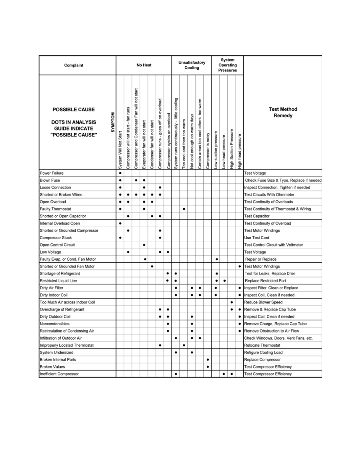
Trouble Shooting Guide
COOLING HEATING
11200/11600 10000/10300
1180/1220 1130/1160
1484 1669
CFM (m
ss Standard efficiency
Fan Type-Piece
Diameter-Length in. (mm) φ7.72X 3.24
Evaporator
Pipe Diameter in. (mm) φ0.25
Row-Fin Gap in. (mm) 3-0.55
Coil length X height X coil width in. (mm) 17.32X9.75X1.5
Swing Motor Model
Output of Swing Motor (W)
Starting Method
Working Temp Range °F (℃) <109.4° F
Condenser
Pipe Diameter in. (mm) φ0.25
Rows-Fin Gap in. (mm)
Coil length X height X coil width in. (mm) 18.75X14.25X1.5
Fan Type-Piece
Fan Diameter in. (mm) φ13.78
Sound Pressure Level dB (A) (H/L)
Sound Power Level dB (A) (H/L)
Defrosting Method
3
/h) 283 (480)
pint/hour (l/h) 3.2 (1.5)
μF)
6.93 8.19
Aluminum fin-copper tube
Aluminum fin-copper tube
RAH-123G
CC05103191_K37718
208~ 230V
60Hz
2.78/2.61
Centrifugal flow fan – 1
(φ196.2X 82)
(φ7)
(3-1.4)
(440X247.65X38.1)
/
/
Capacitor
(<4
(φ7)
3 - .629 (3 -1.6)
(476X361.95X38.1)
Axial fan –1
(φ350)
66/62
76/72
1100/1000/950
75
0.63/0.56
T1
IP24
3° C)
/
4
I
26
Page 28

9/2013
Design, specications, performance data and materials subject to change without notice.
:HOOZRUWK$YH-DFNVRQ0,3KZZZKHDWFRQWUROOHUFRP
 Loading...