

Page 1
APPLICATION, OPERATION
& MAINTENANCE MANUAL
DXM2 Digital
Heat Pump Controller
Heat Controller, Inc. • 1900 Wellworth Ave. • Jackson, MI 49203 • (517)787-2100 • www.heatcontroller.com
Page 2

Application, Operation, & Maintenance Manual DXM2 UNIT CONTROLS Heat Controller, Inc.
Table of Contents
DXM2 Electronic Heat Pump Controls . . . . . . . . . . . . . . . . . . . . . . . . . . . . . . . . . . . . . . . . . . . . . . . . . . . . . . . . . . . . . . . . . . . . . . . . . . . .3
DXM2 Physical Dimensions & Layout . . . . . . . . . . . . . . . . . . . . . . . . . . . . . . . . . . . . . . . . . . . . . . . . . . . . . . . . . . . . . . . . . . . . . . . . . . . .4
DXM2 Layout and Connections . . . . . . . . . . . . . . . . . . . . . . . . . . . . . . . . . . . . . . . . . . . . . . . . . . . . . . . . . . . . . . . . . . . . . . . . . . . . . . . . .5
DXM2 Controls. . . . . . . . . . . . . . . . . . . . . . . . . . . . . . . . . . . . . . . . . . . . . . . . . . . . . . . . . . . . . . . . . . . . . . . . . . . . . . . . . . . . . . . . . . . . . .6
DXM2 Service & Application Notes . . . . . . . . . . . . . . . . . . . . . . . . . . . . . . . . . . . . . . . . . . . . . . . . . . . . . . . . . . . . . . . . . . . . . . . . . . . . .16
Basic Troubleshooting Information. . . . . . . . . . . . . . . . . . . . . . . . . . . . . . . . . . . . . . . . . . . . . . . . . . . . . . . . . . . . . . . . . . . . . . . . . . . . . . 18
Advanced Troubleshooting and Confi guration Information . . . . . . . . . . . . . . . . . . . . . . . . . . . . . . . . . . . . . . . . . . . . . . . . . . . . . . . . . . .19
Troubleshooting Chart . . . . . . . . . . . . . . . . . . . . . . . . . . . . . . . . . . . . . . . . . . . . . . . . . . . . . . . . . . . . . . . . . . . . . . . . . . . . . . . . . . . . . . . 21
DXM2 Wiring Diagram with Motorized Modulating Water Valve - Optional 96B0005N62 . . . . . . . . . . . . . . . . . . . . . . . . . . . . . . . . . . . . 22
DXM2 Wiring Diagram (Standard Installation) - 96B0005N56 . . . . . . . . . . . . . . . . . . . . . . . . . . . . . . . . . . . . . . . . . . . . . . . . . . . . . . . . .23
Functional Troubleshooting . . . . . . . . . . . . . . . . . . . . . . . . . . . . . . . . . . . . . . . . . . . . . . . . . . . . . . . . . . . . . . . . . . . . . . . . . . . . . . . . . . .24
Performance Troubleshooting . . . . . . . . . . . . . . . . . . . . . . . . . . . . . . . . . . . . . . . . . . . . . . . . . . . . . . . . . . . . . . . . . . . . . . . . . . . . . . . . .26
2
Page 3

Heat Controller, Inc. DXM2 UNIT CONTROLS Application, Operation, & Maintenance Manual
DXM2 Electronic Heat Pump Controls
DXM2 OVERVIEW
The manufacturer’s next generation control board, DXM2,
is the geothermal industry’s fi rst two-way communication.
The DXM2 electronic control is a robust, microprocessor
based heat pump controller that is advanced and featureladen for maximum application fl exibility. The DXM2
Control has relay outputs for Compressor, Compressor
Speed, Reversing Valve, Alarm Relay, and 2 confi gurable
relays for Fan, Fan Speed, HWG Pump, and Loop Pump,
and 2 confi gurable accessory relay outputs. For on board
diagnostics, there are 2 LED’s to provide status indication.
There are inputs for safety pressure switches, low
temperature protection thermistors, condensate overfl ow
sensor, DIP switch selection inputs, thermostat inputs, night
setback inputs, and emergency shutdown input. Additional
confi gurable temperature sensor inputs are available that
may be used for hot water, compressor discharge, leaving
air, leaving water, and entering water temperature sensors.
The DXM2 has an RS485 communications port to interface
with a communicating thermostat or other compatible
controls.
DXM2 Controller Part Number:
17B0002N02 DXM2 Control Board
General Operating Parameters
The following are general operating parameters for the
DXM2 Control:
• Operating Environment: -40°F to 176°F and up to 95%
relative humidity, non-condensing.
• Storage Environment: -40°F to 185°F and up to 95%
relative humidity, non-condensing.
Power Requirements
DXM2 only power draw -
• Normally 8 VA draw at 24VAC
• Maximum 12 VA draw at 24VAC. A dedicated 24VAC,
50-60Hz, 1Ph, 40VA transformer minimum is required for
typical WSHP application.
Grounding
The control board must be grounded from one of the C
terminals.
Basic Control Features
• Single or two–stage compressor control
• Anti-short cycle protection
• High pressure cut-out
• Loss of charge cut-out
• High and low voltage cut-outs
• Water coil low temperature cut-out
• Air coil low temperature cut-out
• Random start
• Status LED and Fault LED
• Reset lockout at unit or disconnect
• Condensate overfl ow sensor
• Intelligent fault retry
• Test Mode
• Multiple blower confi guration options
• Electric heat outputs
• Accessory water valve connection
Advanced Control Features
• Direct control of ECM blower
• Intelligent hot water generator control
• Two accessory relays confi gurable for multiple
applications
• Internal Flow Center output
• Proportional valve output
• Night setback with override capability
• Emergency shutdown capability
• Removable thermostat connector for ease of installation
and service
• Accepts conventional heat pump (Y,O) or heat/cool (Y,W)
thermostat types
• RS–485 port to interface with a communicating
thermostat or other compatible controls
• Boilerless electric heat
• Confi gurable inputs and outputs for advanced functions
Relay and Connection Contact Ratings
The following relays are mounted on the DXM2 Control:
• Compressor Relay: 40VA at 24VAC
• Compressor Speed Relay: 28VA at 24VAC
• Alarm Relay: 28VA at 24VAC
• Reversing Valve: 28VA at 24VAC
• Accessory Relay 1: 28VA at 24VAC
• Accessory Relay 2: 28VA at 24VAC
• Fan Enable / Loop Pump Relay: 1 HP at 240VAC
• Fan Speed / HWG Pump Relay: 1 HP at 240VAC
• Connection ratings on the DXM2 Control:
• ‘A’ terminal: 20VA at 24VAC. Larger solenoid valve draw
should be controlled with accessory relays.
3
Page 4
Application, Operation, & Maintenance Manual DXM2 UNIT CONTROLS Heat Controller, Inc.
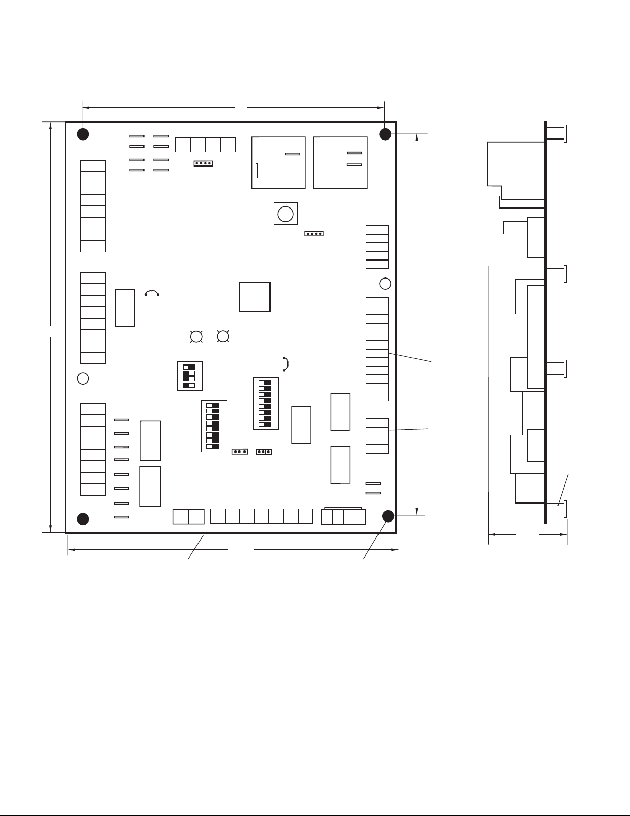
DXM2 Physical Dimensions & Layout
5"
C
Gnd
B-
P1
Y1
Y2
W
O
G
R
C
AL1
R
P2
AL2
R
NSB
C
7"
ESD
OVR
H
A
P3
R
NO1
NC1
COM
NO2
NC2
COM
R
COH
COM
Alarm
Relay
Factory Use
JW1
Acc1
Relay
Acc2
Relay
Off On
P11
AO2
Fault
S3
1 2 3 4
Off On
Gnd
P4
A+ 24V
P5
(240Vac)
Com
Micro
U1
Status
Off On
1 2 3 4 5 6 7 8
S2
A0-1 A0-2
S1
T1
T2 T2 T3 T3 T4 T4
N.O.
Fan Enable
Test
JW3
1 2 3 4 5 6 7 8
Relay
P10
CCH
(240Vac)
Fan Speed
P12
RV
Relay
Comp
Relay
P9
T5
T5
N.C.
N.O.
T6 T6
12
1
1
4
P8
12V
IN
OUT
Gnd
NC
HP
HP
LP
LP
LT1
LT1
LT2
LT2
RV
RV
CO
CO
P7
24Vdc
EH1
EH2
P6
CCG
CC
6 1/2"
Factory low
voltage molex
connection for
unit harness
Factory low
voltage molex
connection for
electric heat
harness
3/8” standoff
Note: There is only
one T1 connection
1.5
5 1/2"
Use 4 mounting screws
#6 sheet metal screw 1” long
4
Page 5
Heat Controller, Inc. DXM2 UNIT CONTROLS Application, Operation, & Maintenance Manual
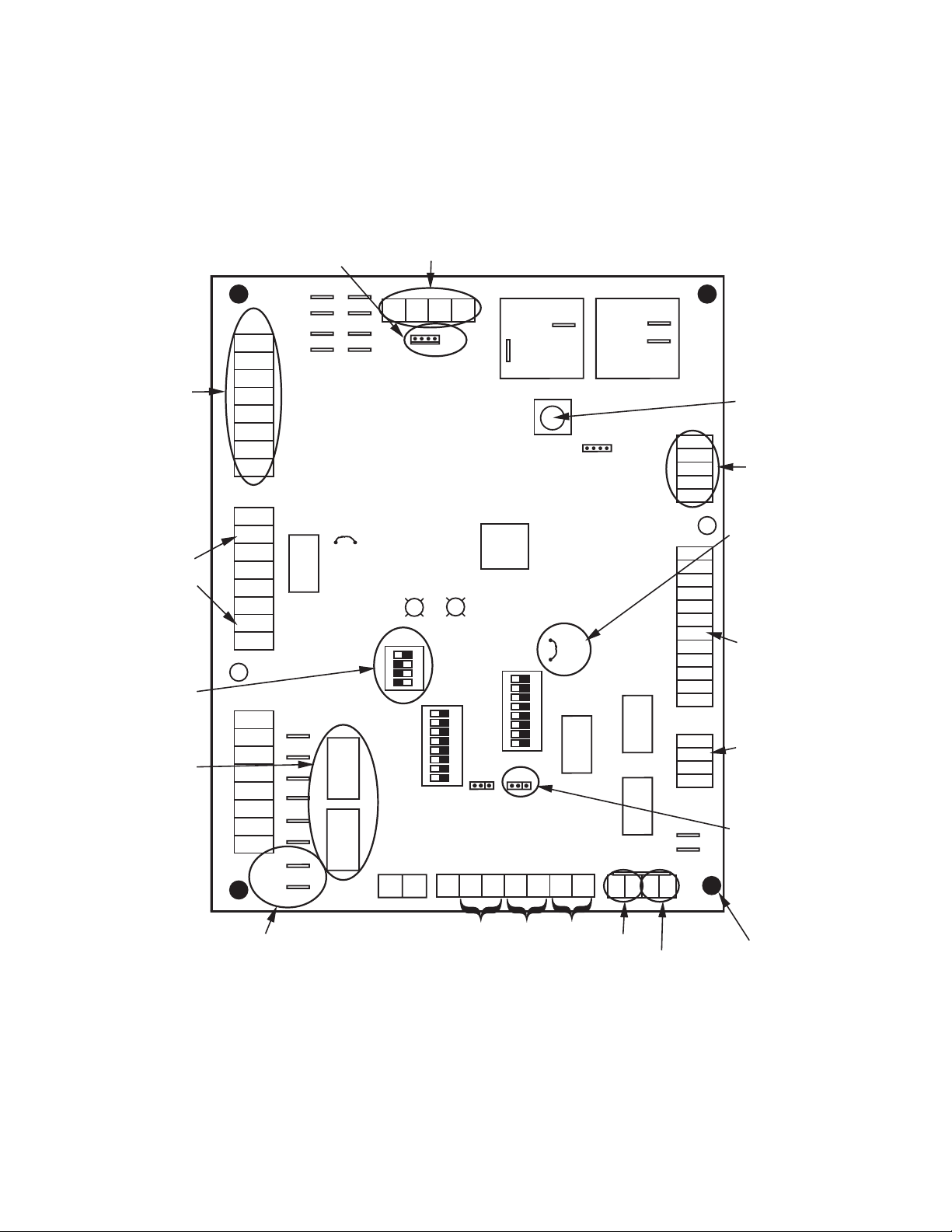
DXM2 Layout and Connections
Conventional
stat connection
Cabinet
temperature
sensor
(with variable
speed pump)
Communications
and HWG
Settings
Accessory
relays refer
to DXM2 AOM
for configuration
P1
Y1
Y2
W
O
G
R
C
AL1
P2
AL2
R
NSB
C
ESD
OVR
H
A
P3
R
NO1
NC1
COM1
NO2
NC2
COM2
R
COH
COM
Service tool
connection
C
R
JW1
Alarm
Relay
Acc1
F
Relay
sU yrotca
e
Acc2
Relay
Communicating
stat connection
Gnd
B-
A+ 24V
P5
Fault
Status
Off On
1 2 3 4
S3
Off On
1 2 3 4 5 6 7 8
S1
P11
T1
Gnd
AO2
P4
(240Vac)
N.O.
Com
Fan Enable
Test
Micro
U1
Off On
S2
A0-1 A0-2
JW3
1 2 3 4 5 6 7 8
CCH
Relay
P10
T2 T2 T3 T3 T4 T4
(240Vac)
Fan Speed
P12
RV
Relay
Comp
Relay
P9
T5
T5
N.C.
N.O.
T6 T6
12
1
1
4
P8
12V
IN
OUT
Gnd
NC
HP
HP
LP
LP
LT1
LT1
LT2
LT2
RV
RV
CO
CO
P7
24Vdc
EH1
EH2
P6
CCG
CC
Test Button
to Speed up
Time Delays
ECM Motor
Connection
Water Coil
Low Temp
Limit Setting.
JWT-LT1 jumper
should be clipped
for low temp
(antifreeze)
operation
Factory low
voltage molex
connection for
unit harness
Electric heat
connection
Configure
Confi gure
modulating valve
Modulating V alve
or variable
(Optional)
speed pump
24V to compressor
second-stage solenoid
for Y2/full
load capacity
Variable
speed pump
water temp
Entering
water temp
5
air temp
Leaving
Leaving
Entering Hot water
Compressor Discharge
Temperature
Use 4 mounting screws
temperature
#6 sheet metal screw
1” long
Page 6

Application, Operation, & Maintenance Manual DXM2 UNIT CONTROLS Heat Controller, Inc.
DXM2 Controls
THERMOSTAT COMPATABILITY - IT IS STRONGLY RECOMMENDED THAT A COMMUNICATING THERMOSTAT (7602-443)
BE USED WITH GEOMAX COMMUNICATING SYSTEMS FOR:
1. Four-wire connections between the thermostat, compressor section (HTS), and air handler (WDG).
2. Confi guring, monitoring and diagnosing the system in
PLAIN ENGLISH on the thermostat.
FIELD SELECTABLE INPUTS
Test mode: Test mode allows the service technician to
check the operation of the control in a timely manner. By
momentarily pressing the TEST pushbutton, the DXM2
control enters a 20 minute test mode period in which all
time delays are sped up 15 times. Upon entering test
mode, the Status and Fault LED displays will change.
The Status LED will either fl ash rapidly to indicate the
control is in the test mode, or display a numeric fl ash
code representing the current airfl ow if an ECM blower is
connected and operating. The Fault LED will display the
most recent fault condition in memory. Note: A fl ash code
of 1 indicates there have been no faults stored in memory.
For diagnostic ease at conventional thermostats, the alarm
relay will also cycle during test mode. The alarm relay will
cycle on and off similar to the Fault LED to indicate a code
representing the last fault, at the thermostat.
The test mode can be exited by pressing the TEST
pushbutton for 3 seconds. The test Mode can also be
entered and exited by cycling the G input, 3 times within a
60 second time period.
During Test Mode, the control monitors to see if the LT1
and LT2 thermistors are connected and operating properly.
If the control is in Test Mode, the control will lockout, with
Code 9, after 60 seconds if:
a) the compressor is On in Cooling Mode and the LT1
sensor is colder than the LT2 sensor. or,
b) the compressor is On in Heating Mode and the LT2
sensor is colder than the LT1 sensor.
Retry Mode: If the control is attempting a retry of a fault,
the Fault LED will slow fl ash (slow fl ash = one fl ash every 2
seconds) to indicate the control is in the process of retrying.
Field Confi guration Options - Note: In the following fi eld
confi guration options, jumper wires should be clipped
ONLY when power is removed from the DXM2 control.
Note: Jumper 3 must not be clipped prior to adding
antifreeze to the water loop. Antifreeze protection to
10°F required. Clipping JW3 without antifreeze may
result in freeze damage and will void the unit warranty.
Water coil low temperature limit setting: Jumper 3 (JW3-
LT1 Low Temp) provides fi eld selection of temperature limit
setting for LT1 of 30°F or 10°F [-1°F or -12°C] (refrigerant
temperature).
Not Clipped = 30°F. Clipped = 10°F.
Alarm Relay Setting - Jumper 1 (JW1-AL2 Dry) provides
fi eld selection of alarm function when Alarm Relay is
energized.
Not Clipped = AL1 connected to R (24VAC) with Alarm
Relay active.
Clipped = Dry contact connection between AL1 and AL2
with Alarm Relay active.
JUMPERS (Set at Factory)
A0-2: Confi gure Modulating Valve (Optional)
Set A0-2 jumper (see Figure on page 5) to “IOV” if using
Internal Modulating Motorized Valve (optional).
DIP SWITCHES
Note: In the following fi eld confi guration options,
DIP switches should only be moved when power is
removed from the DXM2 Control to ensure proper
operation.
DIP Package #1 (S1)
DIP Package #1 is 8 position and provides the following
setup selections.
DIP 1.1: Unit Performance Sentinel Disable - Provides fi eld
selection to disable the UPS feature.
On = Enabled. Off = Disabled.
DIP 1.2: Compressor Relay Staging Operation - Provides
selection of Compressor Relay staging operation. The
Compressor Relay can be selected to turn on with Stage
1 or Stage 2 call from the thermostat. This is used with
Dual Stage units (2 compressors where 2 DXM2 Controls
are being used) or with master/slave applications. In
master/slave applications, each compressor and fan will
stage according to its appropriate DIP 1.2. If set to stage
2, the compressor will have a 3 second on-delay before
energizing during a Stage 2 demand. Also, if set for stage
2, the Alarm Relay will NOT cycle during Test Mode.
On = Stage 1. Off = Stage 2.
DIP 1.3: Thermostat Type (Heat/Cool) - Provides selection
of thermostat type. Heat Pump or Heat/Cool thermostats
can be selected. When in Heat/Cool Mode, Y1 is input call
for Cooling Stage 1, Y2 is input call for Cooling Stage 2,
W1 is input call for Heating Stage 1, and O/W2 is input call
for Heating Stage 2. In Heat Pump Mode, Y1 is input call
for Compressor Stage 1, Y2 is input call for Compressor
Stage 2, W1 is input call for Heating Stage 3 or Emergency
Heat, and O/W2 is the input call for RV (heating or cooling
dependent upon DIP 1.4).
6
Page 7
Heat Controller, Inc. DXM2 UNIT CONTROLS Application, Operation, & Maintenance Manual
DXM2 Controls
On = Heat Pump. Off = Heat/Cool.
DIP 1.4: Thermostat Type (O/B) - Provides selection of
thermostat type. Heat pump thermostats with “O” output on
with Cooling or “B” output on with Heating can be selected.
On = HP Stat with O output with cooling. Off = HP Stat with
B output with heating.
DIP 1.5: Dehumidifi cation Mode - Provides selection of
normal or Dehumidifi cation Fan Mode. In Dehumidifi cation
Mode, the fan speed will be adjusted for Cooling. In Normal
Mode, the fan speed will be normal during Cooling.
On = Normal Fan Mode. Off = Dehumidifi cation Mode.
DIP 1.6: DDC Output at EH2 - DIP Switch 1.6 provides
selection for DDC operation. If set to DDC Output at EH2,
the EH2 terminal will continuously output the last fault code
of the controller. If set to EH2 normal, then the EH2 will
operate as standard electric heat output.
On = EH2 Normal. Off = DDC Output at EH2.
DIP 1.7: Boilerless Operation - Provides selection
of Boilerless Operation. In Boilerless Mode, only the
compressor is used for Heating Mode when LT1 is above
the temperature specifi ed by the setting of DIP 1.8. If DIP
1.8 is set for 50°F, then the compressor is used for heating
as long as LT1 is above 50°F. Below 50°F, the compressor
is not used and the control goes into Emergency Heat
Mode, staging on EH1 and EH2 to provide heating.
On = normal. Off = Boilerless operation.
DIP 1.8: Boilerless Changeover Temperature - Provides
selection of boilerless changeover temperature setpoint.
On = 50°F. Off = 40°F.
DIP Package #2 (S2)
DIP Package #2 (S2) - A combination of dip switches 2.1,
2.2, 2.3, and 2.4, 2.5, 2.6 deliver confi guration of ACC1
and ACC2 relay options respectively. See Table 2 for
description and functionality.
DIP 2.7: Auto Dehumidifi cation Fan Mode or High Fan
Mode - Provides selection of Auto Dehumidifi cation Fan
Mode or High Fan Mode. In Auto Dehumidifi cation Mode,
the Fan Speed will be adjusted during Cooling IF the H
input is active. In High Fan Mode, the Fan will operate on
high speed when the H input is active.
DIP Package #3 (S3)
DIP Package #3 is 4 position and provides the following
setup selections.
DIP 3.1: Communications confi guration: Provides selection
of the DXM2 operation in a communicating system. The
DXM2 may operate as a communicating master or slave
device depending on the network confi guration. In most
confi gurations, the DXM2 will operate as a master device.
On = Communicating Master device (default). Off =
communicating Slave device.
Table 1: Accessory Relay 1 Confi guration
DIP 2.1 DIP 2.2 DIP 2.3 ACC1 Relay Option
ON ON ON Cycle with fan
OFF ON ON Digital night setback
ON OFF ON Water valve – Slow opening
ON ON OFF Outside air damper
OFF ON OFF
OFF OFF OFF option – Humidistat
OFF OFF ON Hydronic Economizer – 1st Stage
ON OFF OFF
All other DIP combinations are invalid
Whole House Dehumidifi cation
option – Dehumidistat
Hydronic Economizer – Both
Stages
Table 2: Accessory Relay 2 Confi guration
DIP 2.4 DIP 2.5 DIP 2.6 ACC2 Relay Option
ON ON ON Cycle with compressor
OFF ON ON Digital night setback
ON OFF ON Water valve – Slow opening
OFF OFF ON Humidifi er
ON ON OFF Outside air damper
All other DIP combinations are invalid
DIP 3.2: HWG Test Mode: Provides forced operation of the
HWG pump output, activating the HWG pump output for up
to fi ve minutes.
On = HWG test mode. Off = Normal HWG mode (default).
DIP 3.3: HWG Temperature: Provides the selection of the
HWG operating setpoint.
On = 150°F [66°C]. Off = 125°F [52°C] (default).
On = Auto Dehumidifi cation Mode (default). Off = High Fan
Mode.
DIP 2.8: Factory Setting - Normal position is On. Do not
change selection unless instructed to do so by the Factory.
DIP 3.4: HWG Status: Provides HWG operation control.
On = HWG mode enabled. Off = HWG mode disabled
(default)
7
Page 8

Application, Operation, & Maintenance Manual DXM2 UNIT CONTROLS Heat Controller, Inc.
DXM2 Controls
SAFETY FEATURES
The following safety features are provided to protect
the compressor, heat exchangers, wiring and other
components from damage caused by operation outside of
design conditions.
Anti-Short Cycle Protection - The control features a 5
minute anti-short cycle protection for the compressor.
Note: The 5 minute anti-short cycle also occurs at
power up.
Random Start - The control features a 5-80 second
random start upon power up. The random start delay will
be present after a control power up and after returning from
Night Setback or Emergency Shutdown modes.
Extended Compressor Operation Monitoring - If the
compressor relay has been on for 4 continuous hours, then
the control will automatically turn off the compressor relay
and wait the short cycle protection time. All appropriate
safeties will be monitored during the off time. If all operation
is normal, and if the compressor demand is still present,
the control will turn the compressor back on.
Fault Retry - In Fault Retry Mode, the Fault LED begins
slow fl ashing to signal that the control is trying to recover
from a fault input. The DXM2 Control will stage off the
outputs and then “try again” to satisfy the thermostat call for
compressor. Once the thermostat input calls are satisfi ed,
the control will continue on as if no fault occurred. If 3
consecutive faults occur without satisfying the thermostat
call for compressor, then the control will go to Lockout
Mode. The last fault causing the lockout will be stored in
memory and is displayed at the Fault LED by entering the
Test mode.
CAUTION!
CAUTION!
remedy of faulting condition. Equipment damage may occur.
the DXM2 is in Lockout Mode, and the W input becomes
active, then Emergency Heat Mode will occur during
Lockout. For Emergency Heat, the fan and auxiliary heat
outputs will be activated.
Fault Code 2: High Pressure Switch – When the High
Pressure switch opens due to high refrigerant pressures,
the compressor relay is de–energized immediately. The
High Pressure fault recognition is immediate (does not
delay for 30 continuous seconds before de–energizing the
compressor). When the Test mode is activated, the Fault
LED will display a fault code of 2 for a High Pressure fault.
Fault Code 3: Loss of Charge Switch – The Loss of
Charge Switch must be open and remain open for 30
continuous seconds during a compressor “on” cycle to
be recognized as a Loss of Charge fault. If the Loss of
Charge switch is open for 30 seconds prior to compressor
power up it will be considered a Loss of Charge fault. The
Loss of Charge Switch input is bypassed for the initial 120
seconds of a compressor run cycle. When the Test mode
is active, the Fault LED will display a fault code of 3 for a
Loss of Charge fault.
Fault Code 4: Water Coil Low Temperature Cut-Out
Limit (LT1) - The control will recognize an LT1 fault, during
a compressor run cycle if:
a) the LT1 thermistor temperature is below the selected
Do not restart units without inspection and
low temperature protection limit setting for at least 50
seconds, AND
Note: LT1 and LT2 faults are factory set for one try, so
there will be no “retries” for LT1 and LT2 faults. The
control will only try one time for these faults.
FAULT CODES
Lockout
fl ashing. The compressor relay is turned off immediately.
The fan output will be turned off after the current blower off
delay unless auxiliary heat is active. The Lockout Mode
can be “soft” reset via the thermostat by removing the call
for compressor, or by a “hard” reset (disconnecting power
to the control). The fault code will be stored in non-volatile
memory that can be displayed by the Fault LED by entering
the Test mode, even if power was removed from the
control.
Lockout with Emergency Heat - If the DXM2 is
confi gured for Heat Pump thermostat Mode (see DIP 1.3),
- In Lockout Mode, the Fault LED will begin fast
b) the LT1 thermistor temperature is rising (getting
warmer) at a rate LESS than 2°F per 30 second time
period.
The LT1 input is bypassed for the initial 120 seconds of a
compressor run cycle. When the Test mode is active, the
Fault LED will display a fault code of 4 for a LT1 fault.
Fault Code 5: Air Coil Low Temperature Cut-Out
(LT2) - The control will recognize an LT2 fault, during a
compressor run cycle if:
a) the LT2 thermistor temperature is below the low
temperature protection limit setting for at least 50
seconds, AND
b) the LT2 thermistor temperature is rising (getting
warmer) at a rate LESS than 2°F per 30 second time
period.
The LT2 input is bypassed for the initial 120 seconds of a
8
Page 9

Heat Controller, Inc. DXM2 UNIT CONTROLS Application, Operation, & Maintenance Manual
DXM2 Controls
compressor run cycle. When the Test mode is active, the
Fault LED will display a fault code of 5 for a LT2 fault.
Fault Code 6: Condensate Overfl ow - The Condensate
Overfl ow sensor must sense overfl ow levels for 30
continuous seconds to be recognized as a CO fault.
Condensate Overfl ow will be monitored at all times
during the compressor run cycle. When the Test mode
is active, the Fault LED will display a fault code of 6 for a
Condensate Overfl ow fault.
Fault Code 7: Over/Under Voltage Shutdown - An
Over/Under Voltage condition exists when the control
voltage is outside the range of 18VAC to 31.5VAC. Over/
UnderVoltage Shutdown is self-resetting in that if the
voltage comes back within range of 18.5VAC to 31VAC for
at least 0.5 seconds, then normal operation is restored.
This is not considered a fault or lockout. If the DXM2 is in
over/under voltage shutdown for 15 minutes, the Alarm
Relay will close. When the Test mode is active, the Fault
LED will display a fault code of 7 for an Over/Under Voltage
Shutdown.
Fault Code 8: Unit Performance Sentinel – UPS – The
UPS feature warns when the heat pump is operating
ineffi ciently. A UPS condition exists when:
a) In Heating Mode with compressor energized, if LT2
is greater than 125°F for 30 continuous seconds, or
b) In Cooling Mode with compressor energized, if LT1
is greater than 125°F for 30 continuous seconds, OR
LT2 is less than 40°F for 30 continuous seconds.
If a UPS condition occurs, the control will immediately go
to UPS warning. The status LED will remain on as if the
control is in Normal Mode. (see “LED and Alarm Relay
Operation Table”). Outputs of the control, excluding Fault
LED and Alarm Relay, will NOT be affected by UPS. The
UPS condition cannot occur during a compressor off cycle.
During UPS warning, the Alarm Relay will cycle on and off.
The cycle rate will be On for 5 seconds, Off for 25 seconds,
On for 5 seconds, Off for 25 seconds, etc. When the Test
mode is active, the Fault LED will display a fault code of 8
for an UPS condition.
Fault Code 9: Swapped LT1/LT2 Thermistors - During
Test Mode, the control monitors to see if the LT1 and LT2
thermistors are connected and operating properly. If the
control is in Test Mode, the control will lockout, with Code
9, after 60 seconds if:
a) the compressor is On in Cooling Mode and the LT1
sensor is colder than the LT2 sensor. Or,
b) the compressor is On in Heating Mode and the LT2
sensor is colder than the LT1 sensor.
When the Test mode is active, the Fault LED will display a
fault code of 9 for a Swapped Thermistor fault.
Fault Code 10: ECM Blower Fault – When operating
an ECM blower, there are two types of ECM Blower fault
conditions that may be detected.
a) An ECM blower fault will be detected and the control
will lockout after 15 seconds of blower operation with
the blower feedback signal reading less than 100
RPM.
b) An ECM blower fault will be detected when the ECM
confi guration is incorrect or incomplete. For this
fault condition, the control will continue to operate
using default operating parameters.
When the Test mode is active, the Fault LED will display a
fault code of 10 for an ECM Blower fault.
Fault Code 11: Low Air Coil Pressure Switch (Whole
House Dehumidifi cation Units Only) – When the Low
Air Coil Pressure switch opens due to low refrigerant
pressure in the cooling or reheat operating mode, the
compressor relay is de–energized immediately. The Low
Air Coil Pressure fault recognition is immediate (does not
delay for 30 continuous seconds before de–energizing
the compressor). When the Test mode is activated, the
Fault LED will display a fault code of 11 for a Low Air Coil
Pressure fault. Note: Low Air Coil Pressure fault will keep
the unit from operating in the cooling or reheat modes, but
heating operation will still operate normally.
Fault Code 12: Low Air Temperature (Whole House
Dehumidifi cation Units Only) – The control will recognize
an Low Air Temperature fault, during cooling, reheat, or
constant fan operation if the LAT thermistor temperature
is below 35 degrees for 30 continuous seconds. When
the Test mode is activated, the Fault LED will display a
fault code of 12 for a Low Air Temperature fault. Note: Low
Air Temperature fault will keep the unit from operating in
the cooling, reheat, or constant fan modes, but heating
operation will still operate normally.
Diagnostic Features
The green Status LED and red Fault LED on the DXM2
Control advise service personnel of the current status of
the DXM2 Control. The LED’s will indicate the current
operating status of the DXM2, as well as the LAST fault in
memory. If there is no fault in memory and the fault display
is selected, the Fault LED will fl ash Code 1. See Table 3 for
a complete listing of codes.
UNIT OPERATION DESCRIPTION
Power Up - The unit will not operate until all the inputs and
safety controls are checked for normal conditions.
9
Page 10

Application, Operation, & Maintenance Manual DXM2 UNIT CONTROLS Heat Controller, Inc.
DXM2 Controls
Note: The compressor will have a 5-minute anti-short
cycle delay at power-up.
Standby/Fan Only - In Standby Mode, the compressor will
be off. The selected fan output(s) and RV relay may be
on if appropriate inputs are present. If there is demand for
constant fan, the appropriate fan output(s) will be activated
for low speed operation, or constant fan airfl ow. If there is
demand for constant high speed fan, the appropriate fan
output(s) will be activated for high speed operation, or high
speed constant fan airfl ow.
Note: DIP1.5 (Dehum Fan Mode Select) has no effect
upon constant fan operation.
The RV relay will not directly track the input demands for
RV, the DXM2 Control will employ “smart RV” control.
This ensures that the RV will only switch positions if the
thermostat has called for a Heating/Cooling Mode change.
Heating Stage 1 - In Heating Stage 1 Mode, the selected
Fan output(s) and the Compressor relay are turned on
immediately. If confi gured as Stage 2 (DIP1.2 = off), then
the Compressor and Fan will not turn on until there is Stage
2 demand. The Compressor relay is turned off immediately
when the Heating Stage 1 demand is removed. The
selected Fan output(s) will turn off after the selected
heating blower off delay, and the control then reverts to
Standby Mode. If there is a Master/Slave situation or a
Dual Compressor situation, all Compressor relays and
related functions will track with their associated DIP1.2.
Heating Stage 2 – In Heating Stage 2 Mode, the selected
Fan output(s) and Compressor relays remain on. The
Compressor Speed relay is turned on, and multi–stage fan
confi gurations switch to the appropriate operating speed
for Heating Stage 2 immediately. The Compressor Speed
relay is turned off immediately when the Heating Stage 2
demand is removed, and multi–speed fan confi gurations
switch to the appropriate operating speed for Heating
Stage 1 immediately, and the control reverts to Heating
Stage 1 Mode. If there is a Master/Slave situation or a Dual
Compressor situation, all Compressor relays and related
functions will track with their associated DIP1.2.
Heating Stage 3 – In Heating Stage 3 Mode, the selected
Fan output, Compressor, and Compressor Speed relays
will remain on. The EH1 output will turn on immediately,
and if the control is operating an ECM Blower, the airfl ow
Table 3: LED and Alarm Relay Output Table
10
Page 11

Heat Controller, Inc. DXM2 UNIT CONTROLS Application, Operation, & Maintenance Manual
DXM2 Controls
will change to the appropriate Heating Stage 3 airfl ow.
With continuing Heating Stage 3 demand, EH2 will turn on
after 10 minutes. EH1 and EH2 are turned off immediately
when the Heating Stage 3 demand is removed, and the
control reverts to Heating Stage 2 Mode. During Heating
Stage 3 Mode, EH2 will be off (or will turn off if already on)
if LT1 is greater than 45°F AND LT2 is greater than 110°F
(LT2 greater than 110°F includes the condition that LT2 is
shorted). This condition will have a 30-second recognition
time.
Emergency Heat - In Emergency Heat Mode, the selected
fan output(s) will be activated at high speed or the
appropriate airfl ow for Emergency Heat, and EH1 is turned
on immediately. With continuing Emergency Heat demand,
EH2 will turn on after 5 minutes. EH1 and EH2 are turned
off immediately when the Emergency Heat demand is
removed. The selected fan output(s) will turn off after the
selected heating blower off delay and the control reverts to
Standby Mode.
Cooling Stage 1 - In Cooling Stage 1 Mode, the selected
fan output(s), Compressor, and RV relays are turned on
immediately. If confi gured as Stage 2 (DIP1.2 = off), then
the compressor and fan will not turn on until there is Stage
2 demand. The Compressor relay is turned off immediately
when the Cooling Stage 1 demand is removed. The
selected Fan output(s) will turn off after the selected
cooling blower off delay, and the control then reverts to
Standby Mode. The RV relay will remain on until there is
a Heating demand. If there is a Master/Slave situation or
a Dual Compressor situation, all Compressor relays and
related functions will track with their associated DIP1.2.
Cooling Stage 2 - In Cooling Stage 2 Mode, the selected
Fan output(s), Compressor, and RV relays remain on. The
Compressor Speed relay is turned on, and multi–stage fan
confi gurations switch to the appropriate operating speed
for Cooling Stage 2 immediately. The Compressor Speed
relay is turned off immediately when the Cooling Stage 2
demand is removed, and multi–speed fan confi gurations
switch to the appropriate operating speed for Cooling
Stage 1 immediately, and the control reverts to Cooling
Stage 1 Mode. If there is a Master/Slave situation or a dual
compressor situation, all compressor relays and related
functions will track with their associated DIP1.2.
Night Low Limit (NLL) Staged Heating - In NLL Staged
Heating Mode, the OVR input becomes active and is
recognized as a call for Heating (OVR is an alternate
means of calling for Heating Mode). In NLL Staged Heating
Mode, the control will immediately go into Heating Stage
1 Mode with an additional 30 minutes of NLL demand,
the control will go into Heating Stage 2 Mode. With an
additional 30 minutes of NLL demand, the control will go
into Heating Stage 3 Mode.
Blower Confi gurations – The DXM2 may be confi gured
to operate several different blowers and blower
confi gurations. The confi gurations include:
a) 2 Speed PSC Blower – The default confi guration of the
DXM2 is to operate for a 2 Speed PSC blower, with the
K1 relay operating as a blower enable relay, and the
K2 relay operating as a blower speed relay. With this
confi guration, the blower enable relay is momentarily
de-activated when the blower speed relay is switched.
For low speed blower operation (Constant Fan, Heating
1, Cooling 1, Cooling 2 with Dehumidifi cation), K1
will be active and K2 will be inactive. For high speed
blower operation (High Speed Constant Fan, Heating 2,
Heating 3, Emergency Heat, Cooling 2), K1 and K2 will
be active.
b) ECM Blower – If the DXM2 is confi gured for an ECM
blower, OR an ECM blower is detected, the DXM2
will directly control an ECM blower using selected
or default airfl ows for each operating mode. When
operating an ECM blower, the K1 relay becomes a
loop pump relay active anytime the compressor relay is
active, and the K2 relay becomes a HWG pump relay.
c) Single Speed PSC Blower – If the DXM2 is confi gured
for a single speed PSC blower, the K1 relay will operate
as the blower relay, and the K2 relay becomes a HWG
pump relay.
d) Dual Stage PSC Blower – If the DXM2 is confi gured for
a dual stage PSC blower, the K1 relay will operate as a
blower enable relay, and the K2 relay will operate as a
blower speed relay. The dual stage PSC confi guration
operates very similar to the 2 Speed PSC, except the
blower enable relay is not de-activated when the blower
speed relay is switched.
e) No Blower – If the DXM2 is confi gured for no blower
(TTS and TTP units), the K1 relay will become a loop
pump relay and the K2 relay will become a HWG pump
relay.
ECM Blower Operation – When the DXM2 is confi gured
to operate an ECM Blower, or an ECM Blower is connected
to the DXM2, the ECM blower will be directly controlled by
the DXM2, with advanced operating features including:
a) Airfl ow Settings – The DXM2 allows the target airfl ow
for each operating mode to be selected individually,
within the allowable operating range.
b) Soft Start Ramping – During the fi rst 2 minutes of
blower operation during a heating or cooling demand,
the ECM blower will ramp up to the selected target
11
Page 12

Application, Operation, & Maintenance Manual DXM2 UNIT CONTROLS Heat Controller, Inc.
DXM2 Controls
airfl ow for the current operating mode. For the fi rst
30 seconds of blower operation, the target airfl ow will
be 50% of the normal target airfl ow. For the next 90
seconds of blower operation, the target airfl ow will
be 75% of the normal target airfl ow. For Constant
Fan, Emergency Heat, and Test Mode operation, the
Soft Start Ramping profi le is bypassed, and the ECM
immediately ramps up to the normal target airfl ow.
c) Blower Off Delays – For ECM blower off delays, the
target airfl ow will be adjusted to 50% of normal target
airfl ow before the beginning of the blower off delay.
d) Default Blower Operation – If the DXM2 confi guration is
incorrect or incomplete with an ECM Blower connected,
the ECM will be operated using default target airfl ows
and operating parameters, and an ECM confi guration
fault will be active.
Hot Water Generator Operation – When the DXM2 is
confi gured to operate a hot water generator pump, the
pump will be directly controlled by the K2 relay, based
on the S3 dipswitch settings and the T5 (hot water
temperature) and T6 (compressor discharge temperature)
inputs. Hot water generator operating features include:
a) HWG operating setpoint selection (S3–3)
Digital Night Setback – If an Accessory relay is confi gured
for Digital NSB, the Accessory relay will be on any time the
NSB input is connected to Ground “C”.
Note: If there are no Accessory relays confi gured
for Digital NSB, and the DXM2 is not connected
to a communicating thermostat confi gured for
night setback, then the NSB and OVR inputs are
automatically confi gured for “mechanical” operation.
See Mechanical NSB operation below.
Note: Digital Night Setback feature requires a
compatible thermostat. Contact the manufacturer for
information on compatible thermostats.
Mechanical Night Setback – When the NSB input is
connected to Ground “C”, all thermostat inputs (G, Y1,
Y2, W, and O) are ignored. A thermostat setback Heating
call can then be connected to the OVR input. If the OVR
input becomes active, then the DXM2will enter NLL Staged
Heating Mode. NLL Staged Heating Mode would then
provide heating during the NSB period.
Water Valve/Slow Opening
confi gured for Water Valve/Slow Opening, the Accessory
relay will turn on 60 seconds prior to the Compressor Relay
turning on.
– If an Accessory relay is
b) Temperature offset verifi cation for effi cient HWG
operation
c) HWG test mode (S3–2)
Proportional Valve Operation – When the DXM2 is
confi gured to operate a proportional valve (optional),
the valve will be directly controlled by the DXM2. For
controlling the proportional valve, the DXM2 monitors the
entering water temperature and leaving water temperature.
The valve is controlled in the following way:
a) Maintain the appropriate temperature difference across
the water coil (EWT–LWT for heating, LWT–EWT for
cooling).
b) Maintain the leaving water temperature below the
appropriate Maximum Heating LWT and above the
Minimum Cooling LWT limits.
SPECIAL DXM2 APPLICATION NOTES / ACCESSORY
RELAYS
Generally the following applications are based upon
confi guring the accessory relays.
Cycle with Fan – If Accessory relay 1 is confi gured to
“cycle with fan”, Accessory relay 1 will be on any time the
Fan Enable relay, or ECM Blower is on.
Cycle with Compressor – If Accessory relay 2 is
confi gured to “cycle with compressor”, Accessory relay 2
will be on any time the Compressor relay is on.
Outside Air Damper – If an Accessory relay is confi gured
for OAD, the Accessory relay will normally turn on any
time the Fan Enable relay is on. But, following a return
from NSB (NSB input no longer connected to Ground “C”)
to Normal Mode, the Accessory Relay will not turn on for
30 minutes even if the Fan Enable Relay is on. After this
30-minute timer expires, the Accessory Relay will turn on if
the Fan Enable Relay is on.
Humidifi er – If Accessory relay 2 is confi gured for a
Humidifi er, the Accessory relay will be on any time the H
input is active.
Hydronic Economizer – If Accessory relay 1 is confi gured
to be used as a hydronic economizer, normal cooling
operation will be modifi ed.
If Accessory relay 1 is confi gured as a single stage
hydronic economizer, when a fi rst stage cooling demand is
present and the H input is active, the accessory relay will
be activated instead of the compressor output. All other
heat pump operating modes will operate normally, and the
accessory relay will be off in all other operating modes.
If Accessory relay 1 is confi gured as a hydronic economizer
for both stages, when a fi rst stage cooling demand is
present and the H input is active, the accessory relay will
be activated instead of the compressor output. When a
second stage cooling demand is present with the H input
active, the accessory relay will be activated in addition
12
Page 13

Heat Controller, Inc. DXM2 UNIT CONTROLS Application, Operation, & Maintenance Manual
DXM2 Controls
to the compressor output. All other heat pump operating
modes will operate normally, and the accessory relay will
be off in all other operating modes.
Thermostat Inputs – Table 5 shows the resulting demand
from differing combinations of inputs.
Y1 – Y1 is the input for compressor stage 1 if DIP1.3 = on.
Y1 is the input for Cooling Stage 1 if DIP1.3 = off.
Y2 – Y2 is the input for compressor stage 2 if DIP1.3 = on.
Y2 is the input for Cooling Stage 2 if DIP1.3 = off.
W – If Y1 and Y2 are active and DIP1.3 = on, then W is the
input for Heating Stage 3. If Y1 and Y2 are not active and
DIP1.3 = on, then W is the input for Emergency Heat. If
DIP1.3 = off, then W is the input for Heating Stage 1.
O – O is the input for Reversing Valve Relay if DIP1.3 =
on and DIP1.4 = on. O is the input for Heating Stage 2 if
DIP1.3 = off. O is the input for “Heat Mode” if DIP1.3 = on
and DIP1.4 = off; this means that the thermostat outputs a
“B” call when in Heating Mode and does NOT have an “O”
output. The DXM2 Control will employ “Smart RV” control.
This ensures that the RV will only switch positions if the
thermostat has called for a Heating/Cooling Mode change.
G – G is the input for Constant Fan Operation.
go to Night Setback Setpoints. Stated differently, when
confi gured for Digital NSB Mode, the Accessory Relay
directly tracks the NSB input.
Note: Digital Night Setback feature requires a
compatible thermostat. Contact the manufacturer for
information on compatible thermostats.
When Digital NSB is NOT selected via the Accessory
Relays Dipswitch inputs and a communicating thermostat
confi gured for night setback is not connected, when the
NSB input is connected to Ground “C”, then Y1, Y2, W, O,
and G inputs are ignored. During this time period, if OVR is
momentarily connected to 24VAC, then Y1, Y2, W, O, and
G are once again monitored for 2 hours. After the 2 hour
override period, the DXM2 reverts back to ignoring Y1, Y2,
W1, O, and G, assuming the NSB input is still connected
to Ground “C”. There will be a random start timer when
coming back from NSB Mode.
Note: The maximum number of DXM2Controls with
daisy-chained “NSB” terminals is 75. Also, the
maximum total wire resistance of the “NSB” wiring is
500 Ohms.
NSB and Override – NSB is the input for Night Setback
Mode. When Digital NSB is selected via the Accessory
Relays Dipswitch inputs and the NSB input is connected to
Ground “C”, then the appropriately confi gured Accessory
Relay is turned on to signal the digital thermostat to
OVR – OVR is the input for Night Setback Override or
Night Low Limit Staged Heating input (NLL). When Digital
NSB is NOT selected via the Accessory Relays Dipswitch
inputs and a communicating thermostat confi gured for night
Table 4: Thermostat Inputs With Resulting Demands
Thermostat Operating Modes
3
Input
Mode
O G Y1 Y2
No Demand ON/OFF OFF OFF OFF OFF OFF ON/OFF OFF OFF OFF OFF OFF
Fan Only ON/OFF ON OFF OFF OFF OFF ON/OFF ON OFF OFF OFF OFF
Cooling 1st Stage ON ON ON OFF OFF OFF ON ON ON OFF OFF OFF
Cooling 2nd Stage ON ON ON ON OFF OFF ON ON ON ON OFF OFF
Cooling & Dehumidistat
Dehumidistat Only ON/OFF OFF OFF OFF OFF ON ON ON ON ON OFF ON
Heating 1st Stage OFF ON ON OFF OFF OFF OFF ON ON OFF OFF OFF
Heating 2nd Stage OFF ON ON ON OFF OFF OFF ON ON ON OFF OFF
Heating 3rd Stage OFF ON ON ON ON OFF OFF ON ON ON ON OFF
1
ON ON ON ON/OFF OFF ON ON ON ON ON/OFF OFF OFF
4
W H / DH RV Fan
Output
1st stg
H/C
2nd stg
4
H/C
AUX Reheat
1
Cooling input takes priority over dehumidifi cation input.
3
Above inputs assume DIP 1.3 is in the heat pump position, and DIP 1.4 is in the O position. When 1.3 is in the heat/cool position, Y1 & Y2 are used for
cooling inputs; W and O are used for heating inputs. When 1.4 is in the B position, the O column would be opposite logic.
4
N/A for single stage units; Full load operation for dual capacity units.
5
ON/OFF = Either ON or OFF; H/C = Either Heating or Cooling.
13
Page 14

Application, Operation, & Maintenance Manual DXM2 UNIT CONTROLS Heat Controller, Inc.
DXM2 Controls
setback is not connected and NSB is connected to Ground
“C”, then if OVR is momentarily connected to 24VAC
(minimum 1 second) then the OVR input is recognized
as a Night Setback Override signal and the DXM2Control
reverts from Night Setback and begins monitoring
thermostat inputs for heating and cooling calls for a 2 hour
override period. If NSB is connected to ground “C”, then if
OVR is continuously connected to 24VAC, then the OVR
input is recognized as a call for NLL Staged Heating and
the control enters NLL Staged Heating.
ESD – ESD is the input for Emergency Shutdown Mode.
When the ESD input is connected to Ground “C”, all inputs
are ignored and all outputs are turned off. There will be a
random start timer when coming back from ESD.
H – The H input function is determined by the setting of
DIP2.7, assuming the control is not controlling a internal
fl ow center or an accessory relay is not confi gured for
Whole House Dehumidifi cation or humidifi er operation.
If DIP2.7 = on then the H input is defi ned as Automatic
Dehumidifi cation Mode and is used as an “automatic”
Table 5: System Inputs with the resulting demand.
Table 5 describes demand changes with differing system input (ESD,
NSB, OVR) and DIP input settings. Resulting Demand #1 is derived from
Table 4.
Resulting Demand
#1 (From Table 4)
- X - - - ESD
Invalid - - - - Invalid
All (Excluding Invalid) - - - - All (Excluding Invalid)
All (Excluding Invalid) - - M - All (Excluding Invalid)
C1, C2 - - X - Invalid
OFF, F, H1, H2, or H3 - - X - NLL Staged Heating
EH - - X - EH
All (Excluding Invalid) - X - Mechanical Standby/OFF
All (Excluding Invalid) - X M Mechanical
C1, C2 - X X Mechanical Invalid
OFF, F, H1, H2, or H3 - X X Mechanical NLL Staged Heating
EH - X X Mechanical EH
All (Excluding Invalid) - X -
All (Excluding Invalid) - X M
C1, C2 - X X
OFF, F, H1, H2. or H3 - X X
EH - X X
“M” is momentary input
“X” is continuous input
System Inputs
ESD NSB OVR
NSB Type
Digital /
Comm
Digital /
Comm
Digital /
Comm
Digital /
Comm
Digital /
Comm
Resulting
Demand #2
(After ESD, NSB)
All for 2 hours and
then revert to Stand-
by/OFF (Excluding
Invalid)
All (Excluding Invalid)
All (Excluding Invalid)
Invalid
NLL Staged Heating
EH
counterpart to DIP1.5, meaning if H is connected to
24VAC then the selected fan outputs will operate using
dehumidifi cation speeds and airfl ow settings for cooling. If
H is not connected to 24VAC then the selected fan outputs
will operate using normal speeds and airfl ow settings for
cooling.
If DIP2.7 = off then the H input is defi ned as High Speed
Fan input and is used as an input to call for High Speed
Fan. If the control is in normal operating modes such as
Standby, Cooling or Heating AND the H input is connected
to 24VAC, then the selected fan outputs will operate
using high speed, or high speed airfl ows at all times (this
operation is a high speed fan version of the G input).
Other Outputs
Electric Heat – Outputs EH1 and EH2 turn on whenever
the DXM2 Control is in the following modes: Heating Stage
3, Emergency Heat, and Boilerless Operation.
Status LED – The Status LED is green. The Status LED
indicates the operating status of the DXM2 Control. See
Table 4: “LED and Alarm Relay Operation”.
Fault LED – The Fault LED is red. The Fault LED displays
the current operating status of the control, or fl ashes the
corresponding code for the last fault that has occurred
if the test mode is active. If there is no fault in memory,
then the Fault LED will fl ash Code 1. If the Fault type is
“Primary” (HP, LP, LT1, LT2, or CO) then the Fault type will
always be retained in memory (Primary faults will overwrite
Secondary faults). If the Fault type is “Secondary” (Over/
Table 6: "H" input with resulting demand modes.
Table 6 describes demand changes with “H” input and DIP 2.1-2.3, and
2.7 settings. Resulting Demand #2 is derived from Table 5.
Resulting Demand
#2 (From Table 5)
Standby/OFF X Auto Dehum Mode Standby/OFF with Auto
Dehum enabled
Standby/OFF X High Fan Mode F2
F1 X Auto Dehum Mode F1 with Auto Dehum enabled
F1 X High Fan Mode F2
C1 X Auto Dehum Mode C1 with fan destage
C1 X High Fan Mode *Cooling with High Fan
C2 X Auto Dehum Mode C2 with fan destage
C2 X High Fan Mode *Cooling with High Fan
H1 X Auto Dehum Mode H1
H1 X High Fan Mode Heating with High Fan
H2 X - H2
H3 X - H3
EH X - EH
Invalid - - Invalid
* = signifi es that High Fan is locked on regardless of any Dehum demands
14
Auto Dehum / F2
H
DIP 2.7
Resulting Demand # 3 (After
DIP 2.1-2.3, 2.7 Logic)
Page 15

Heat Controller, Inc. DXM2 UNIT CONTROLS Application, Operation, & Maintenance Manual
DXM2 Controls
Under Voltage, UPS or Swapped LT1/LT2) then the Fault
type will only be retained if there are no “Primary” faults in
memory. The Secondary Fault types will not “overwrite” the
Primary fault memory. See Table 3: “LED and Alarm Relay
Operation”.
Communications
The DXM2 has a single RS485 communications port that
provides communication capabilities for communicating
thermostats or connecting with other communicating
controls.
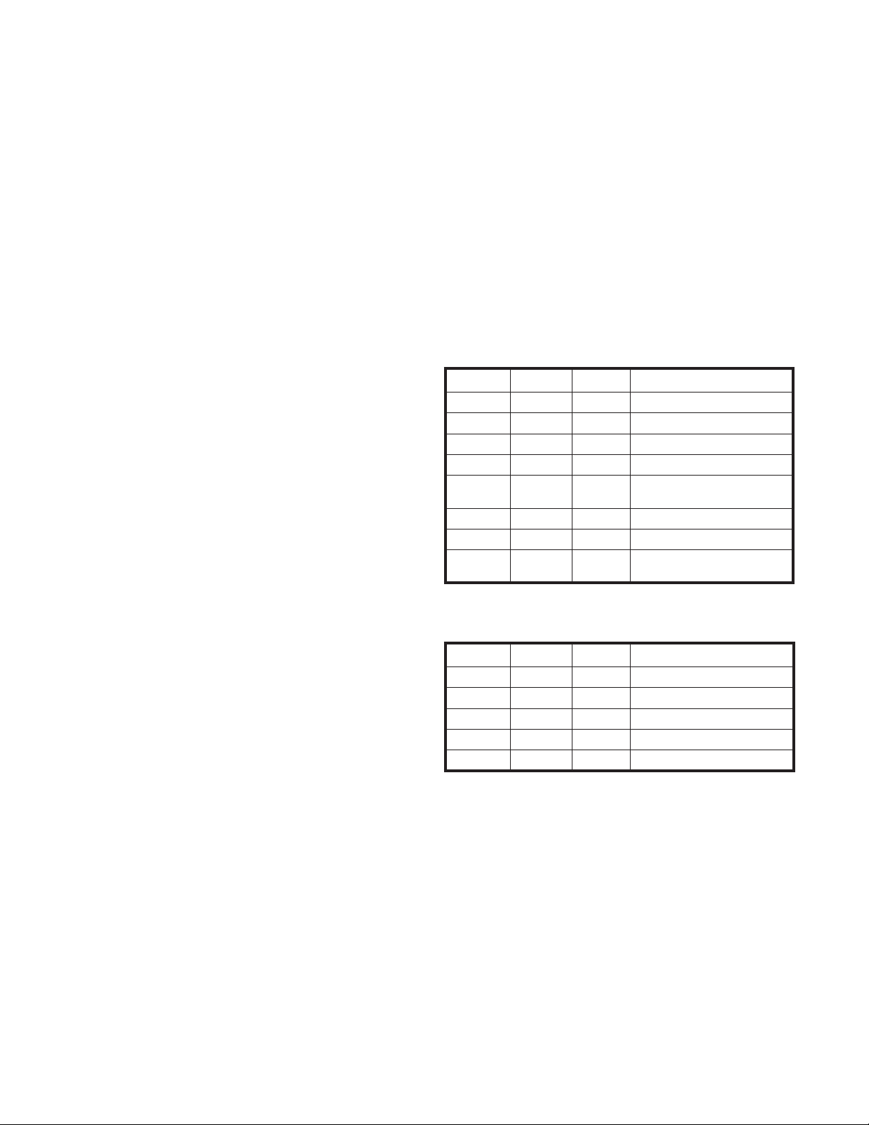
DXM2 SENSORS
Table 7: Replacement Thermistor LT1,
LT2 Part Numbers
Thermistor
Type
LT1 (Gray)
LT2 (Violet)
Tube
OD
3/8,
1/2
5/8,
7/8
3/8,
1/2
5/8,
7/8
36 48 96 192
17B0005N06 N/A 17B0005N04 N/A
N/A N/A 17B0004N01 N/A
N/A 17B0005N02 N/A 17B0005N05
N/A N/A N/A 17B0004N02
Lead Length (in.)
15
Page 16

Application, Operation, & Maintenance Manual DXM2 UNIT CONTROLS Heat Controller, Inc.
DXM2 Service & Application Notes
Pressure Switches
All pressure switches are designed to be normally closed
during normal operating conditions, and to open upon fault.
Condensate Sensor – The Condensate Sensor input will
fault upon sensing impedance less than 100,000 Ohms for
30 continuous seconds. The recommended design uses
a single wire terminated with a male 1/4” quick connect
located in the drain pan at desired trip level. Upon a high
condensate level the water will short between the air coil
and the quick connect producing a resistance less than
100,000 Ohms. Since condensate is free of impurities,
it has no conductivity. Only the impurities from the drain
pan and coil dust or dirt create the conductance. A second
ground wire with appropriate terminal to the drain pan can
be used with the control to replace the air coil ground path.
The Condensate Sensor can also essentially be any open
contact that closes upon a fault condition.
Thermistor Temperature Sensors – The thermistors used
with the DXM2 are NTC (negative temperature coeffi cient)
type. Table 7 shows the replacement part numbers for the
LT1 and LT2 thermistors. The sensors have a 1% tolerance
and follow the characteristics shown in Table 8. Table 9
shows the nominal resistance at any given temperature
and can be used for fi eld service reference. The sensor will
use a minimum of 24 awg wire.
Table 8: 1% Sensor Calibration Points
Minimum
Temp (°F)
Resistance
(Ohm)
78.5 9523 9715 9619
77.5 9650 9843 9746
76.5 10035 10236 10135
75.5 10282 10489 10385
33.5 30975 31598 31285
32.5 31871 32512 32190
31.5 32653 33310 32980
30.5 33728 34406 34065
1.5 80624 82244 81430
0.5 83327 85002 84160
0.0 84564 86264 85410
Maximum
Resistance
(Ohm)
Nominal
Resistance
(Ohm)
Table 9: Nominal resistance at
various temperatures
Temp (ºC) Temp (ºF)
-17.8 0.0 85.34 55 131.0 2.99
-17.5 0.5 84.00 56 132.8 2.88
-16.9 1.5 81.38 57 134.6 2.77
-12 10.4 61.70 58 136.4 2.67
-11 12.2 58.40 59 138.2 2.58
-10 14.0 55.30 60 140.0 2.49
-9 15.8 52.38 61 141.8 2.40
-8 17.6 49.64 62 143.6 2.32
-7 19.4 47.05 63 145.4 2.23
-6 21.2 44.61 64 147.2 2.16
-5 23.0 42.32 65 149.0 2.08
-4 24.8 40.15 66 150.8 2.01
-3 26.6 38.11 67 152.6 1.94
-2 28.4 36.18 68 154.4 1.88
-1 30.2 34.37 69 156.2 1.81
0 32.0 32.65 70 158.0 1.75
1 33.8 31.03 71 159.8 1.69
2 35.6 29.50 72 161.6 1.64
3 37.4 28.05 73 163.4 1.58
4 39.2 26.69 74 165.2 1.53
5 41.0 25.39 75 167.0 1.48
6 42.8 24.17 76 168.8 1.43
7 44.6 23.02 77 170.6 1.39
8 46.4 21.92 78 172.4 1.34
9 48.2 20.88 79 174.2 1.30
10 50.0 19.90 80 176.0 1.26
11 51.8 18.97 81 177.8 1.22
12 53.6 18.09 82 179.6 1.18
13 55.4 17.26 83 181.4 1.14
14 57.2 16.46 84 183.2 1.10
15 59.0 15.71 85 185.0 1.07
16 60.8 15.00 86 186.8 1.04
17 62.6 14.32 87 188.6 1.01
18 64.4 13.68 88 190.4 0.97
19 66.2 13.07 89 192.2 0.94
20 68.0 12.49 90 194.0 0.92
21 69.8 11.94 91 195.8 0.89
22 71.6 11.42 92 197.6 0.86
23 73.4 10.92 93 199.4 0.84
24 75.2 10.45 94 201.2 0.81
25 77.0 10.00 95 203.0 0.79
26 78.8 9.57 96 204.8 0.76
27 80.6 9.16 97 206.6 0.74
28 82.4 8.78 98 208.4 0.72
29 84.2 8.41 99 210.2 0.70
30 86.0 8.06 100 212.0 0.68
31 87.8 7.72 101 213.8 0.66
32 89.6 7.40 102 215.6 0.64
33 91.4 7.10 103 217.4 0.62
34 93.2 6.81 104 219.2 0.60
35 95.0 6.53 105 221.0 0.59
36 96.8 6.27 106 222.8 0.57
37 98.6 6.01 107 224.6 0.55
38 100.4 5.77 108 226.4 0.54
39 102.2 5.54 109 228.2 0.52
40 104.0 5.33 110 230.0 0.51
41 105.8 5.12 111 231.8 0.50
42 107.6 4.92 112 233.6 0.48
43 109.4 4.72 113 235.4 0.47
44 111.2 4.54 114 237.2 0.46
45 113.0 4.37 115 239.0 0.44
46 114.8 4.20 116 240.8 0.43
47 116.6 4.04 117 242.6 0.42
48 118.4 3.89 118 244.4 0.41
49 120.2 3.74 119 246.2 0.40
50 122.0 3.60 120 248.0 0.39
51 123.8 3.47 121 249.8 0.38
52 125.6 3.34 122 251.6 0.37
53 127.4 3.22 123 253.4 0.36
54 129.2 3.10
Resistance
(kOhm)
Temp (ºC) Temp (ºF)
Resistance
(kOhm)
16
Page 17

Heat Controller, Inc. DXM2 UNIT CONTROLS Application, Operation, & Maintenance Manual
DXM2 Service & Application Notes
DXM2 Thermostat Details
THERMOSTAT COMPATABILITY - IT IS STRONGLY RECOMMENDED THAT A COMMUNICATING THERMOSTAT (7602-443)
BE USED WITH GEOMAX COMMUNICATING SYSTEMS FOR:
1. Four-wire connections between the thermostat, compressor section (HTS), and air handler (WDG).
2. Confi guring, monitoring and diagnosing the system in
PLAIN ENGLISH on the thermostat.
Thermostat Compatibility
Most all heat pump and heat/cool thermostats can
be used with the DXM2 Control. For additional
diagnostic capabilities, the communicating thermostat is
recommended.
Anticipation Leakage Current
Maximum leakage current for “Y1” is 50mA and for “W”
is 20mA. Triacs can be used if leakage current is less
than above. Thermostats with anticipators can be used if
anticipation current is less than that specifi ed above.
Thermostat Signals
• “Y1”, “Y2”, “W”, “O”, and “G” have a 1 second
recognition time when being activated or being
removed.
• “R” and “C” are from the transformer.
• “AL1” and “AL2” originate from the Alarm Relay.
• “A” is paralleled with the compressor output for use
with well water solenoid valves.
Safety Listing
The DXM2 Control is listed under UL 873, and is CE listed
under IEC 60730.
17
Page 18

Application, Operation, & Maintenance Manual DXM2 UNIT CONTROLS Heat Controller, Inc.
Basic Troubleshooting Information
General Troubleshooting
Basic DXM2 board troubleshooting in general is best
summarized as simply verifying inputs and outputs.
After this process has been verifi ed, confi dence in board
operation is confi rmed and the trouble must be else where.
Below are some general guidelines required for developing
training materials and procedures when applying the DXM2
Control.
DXM2 Field Inputs
All conventional inputs are 24VAC from the thermostat and
can be verifi ed using a voltmeter between C and Y1, Y2,
W, O, and G.
Sensor Inputs
All sensor inputs are ‘paired wires’ connecting each
component with the board. Therefore continuity on
pressure switches can be checked at the board connector.
The thermistor resistance should be measured with the
connector removed so that only the impedance of the
thermistor is measured. If desired, this reading can be
compared to the chart shown in the thermistor section
of this manual based upon the actual temperature of the
thermistor clip. An ice bath can be used to check calibration
of a thermistor if needed.
DXM2 Outputs
The compressor relay is 24VAC and can be verifi ed using
a voltmeter. The Alarm Relay can either be 24VAC as
shipped or dry contacts (measure continuity during fault)
for use with DDC by clipping the J4 jumper. Electric heat
outputs are 24VDC and require a voltmeter set for DC to
verify operation. When troubleshooting, measure from
24VDC terminal to EH1 or EH2 terminals.
Test Mode
Test Mode can be entered for 20 minutes by pressing
the Test button. For Diagnostic ease at a conventional
thermostat, the Alarm Relay will also cycle during test
mode. The Alarm Relay will cycle on and off similar to the
Fault LED to indicate a code representing the last fault, at
the thermostat. Test Mode can also be entered and exited
by cycling the G input, 3 times within a 60 second time
period.
18
Page 19

Heat Controller, Inc. DXM2 UNIT CONTROLS Application, Operation, & Maintenance Manual
Advanced Troubleshooting and Confi guration Information
General
To properly confi gure and troubleshoot advanced control
features, and to aid in troubleshooting basic control
features, a communicating thermostat or diagnostic tool
with similar capabilities should be used.
System Confi guration
All factory installed DXM2 controls have their basic
confi guration parameters set as part of the factory
manufacturing and test process. The System Confi guration
option under the communicating thermostat Installer menu
provides the installer with the ability to adjust ECM target
airfl ows for each operating mode, set control options, setup
the loop confi guration and parameters, and confi gure fi eld
replacement controls.
Airfl ow Selection – The Airfl ow Selection menu allows the
installer to adjust the ECM target airfl ow for each control
operating mode, as well as independently set the heating
and cooling blower off delays.
ECM Airfl ows – Independent airfl ow selections may be
made for each stage of heating operation, each stage of
cooling operation with and without dehumidifi cation, as
well as constant fan operation. The DXM2 control has set
minimum and maximum airfl ow limits for each operating
mode, based on the unit confi guration that may not be
changed.
Unit Confi guration – Selections under the Unit
Confi guration menu are normally set at the factory as a
normal part of the manufacturing and test process. This
menu allows the confi guration to be modifi ed for special
applications, or to confi gure fi eld replacement controls.
The Unit Confi guration menu provides the ability to select
the Heat Pump Family, Unit Size, Blower Type, and Loop
Type. The Heat Pump Family, Unit Size, and Blower
Type are needed to properly operate any particular unit
confi guration, especially those with ECM blowers.
Heat Pump Family – When replacing a control in the
the Heat Pump Family value must be set for proper blower
and loop operation. The valid family values (HEV/H and
other Communicating units) are available for the user to
scroll through to select the proper value.
Heat Pump Size – When replacing a control in the fi eld,
the Heat Pump Size value must be set for proper blower
operation. After a Heat Pump Family has been selected,
the valid Heat Pump Size values will be available for the
user to scroll through to select the proper value.
Blower Type – When replacing a control in the fi eld, the
Blower Type value must be set for proper operation. The
valid Blower Type values will be available for the user
to scroll through to select the appropriate value from No
Blower, ECM Blower, or PSC confi gurations.
fi eld,
Non-ECM Confi guration – If the DXM2 is not confi gured to
control an ECM blower, the airfl ow selections will not be
available on the Airfl ow Selection menu.
Heating / Cooling Off Delays – The heating and cooling
mode blower off delay times may be independently
adjusted by the user. Each delay time may be set between
0 and 255 seconds.
Option Selection – The Option Selection menu allows the
installer to set selected control options.
LT2 Setpoint – The LT2 setpoint should be set to ANTIFREEZE ONLY when the unit is confi gured as a water-to-
water unit with anti–freeze in the load side loop. For ALL
other unit confi gurations, the LT2 setpoint should be set to
WATER.
Motorized Valve – The Motorized Valve option should be
set to ON when a motorized water valve with end switch
wired to the DXM2 Y1 is used with a communicating
thermostat. For all other system confi gurations, the
Motorized Valve option should be set to OFF.
Loop Confi guration – When replacing a control in the
fi eld, the Loop Confi guration value must be set for
proper operation. The valid Loop Confi guration values
will be available for the user to scroll through to select
the appropriate value from VS PUMP, MOD VALVE, or
OTHER.
Loop Confi guration – The Loop Confi guration menu allows
the installer to set the operating parameters for either
an internal fl ow center, or a proportional water valve,
depending on the unit confi guration.
Heating Delta T – The Heating Delta T option allows the
target delta T (EWT – LWT) value selection for operating
in the heating mode. The DXM2 control has set minimum
and maximum delta T limits that may not be changed.
Cooling Delta T – The Cooling Delta T option allows the
target delta T (LWT – EWT) value selection for operating in
the cooling mode. The DXM2 control has set minimum and
maximum delta T limits that may not be changed.
19
Page 20

Application, Operation, & Maintenance Manual DXM2 UNIT CONTROLS Heat Controller, Inc.
Advanced Troubleshooting and Confi guration Information
Service Mode
The Service Mode provides the installer with several
functions for troubleshooting, including Manual Operation,
Control Diagnostics, Control Confi guration, and Fault
History.
Manual Operation – The Manual Operation mode allows
the installer to bypass normal thermostat timings and
operating modes, to directly activate the thermostat
inputs to the DXM2, activate the DXM2 Test mode, and
directly control the ECM blower, internal fl ow center, and
proportional valve.
Control Diagnostics – The Control Diagnostics menus allow
the installer to see the current status of all DXM2 control
switch inputs, values of all temperature sensor inputs,
control voltage, ECM blower, internal fl ow center, and
proportional valve operating status and parameters.
Dipswitch Confi guration – The Dipswitch Confi guration
menus allow the installer to easily see the current DXM2
control confi guration.
Fault History – In addition to the fault code, the DXM2
stores the status of all control inputs and outputs when a
fault condition is detected. The fault history covering the
last fi ve lockout conditions is stored and may be retrieved
from the DXM2. After a specifi c fault in the fault history
is selected, the operating mode and time when the fault
occurred are displayed, with options to select specifi c
control status values when the lockout occurred.
Fault Temp Conditions – This option displays the DXM2
temperature and voltage values when the lockout occurred.
Fault Flow Conditions – This option displays the DXM2
ECM blower, pump, and valve operating parameters when
the lockout occurred.
Fault I/O Conditions – This option displays the status of
the DXM2 physical and communicated inputs and the relay
outputs when the lockout occurred.
Fault Confi guration Conditions – This option displays the
status of the DXM2 option selections when the lockout
occurred.
Fault Possible Causes – This option displays a list of
potential causes of the stored fault.
Clear Fault History – The Clear Fault History option allows
the fault history stored in the non-volatile memory of the
DXM2 to be cleared.
20
Page 21

Heat Controller, Inc. DXM2 UNIT CONTROLS Application, Operation, & Maintenance Manual
Troubleshooting Chart
Use the following troubleshooting fl ow chart to fi nd appropriate troubleshooting strategies on the following pages
for the DXM2 control and most water source heat pump applications.
See “Unit
short
cycles”
See “Only
Fan Runs”
See “Only
Comp
Runs”
See “Does
not Operate
in Clg”
Attempt to
Lockout at
Start-up?
Yes
Yes
Yes
No
Unit Short
Only Fan
Compressor
Did unit lockout
after a period of
operation?
Does unit
operate in
Start
Did Unit
Start?
Yes
Did Unit
No
Cycles?
No
Runs?
No
Only
Runs?
No
No
cooling?
Yes
DXM2 Functional
Troubleshooting Flow Chart
No
Yes
Yes
Check Main
power (see power
problems)
Check fault code on communicating
thermostat (ATC32) or Configuration
and Diagnostics Tool (ACD01)
See fault codes in table
on following page
No fault
shown
Replace
DXM2
Unit is OK!
‘See Performance
Troubleshooting’ for
further help
21
Page 22

Application, Operation, & Maintenance Manual DXM2 UNIT CONTROLS Heat Controller, Inc.
DXM2 Wiring Diagram with Motorized Modulating W ater Valve - Optional
96B0005N62
024-060
7602-443
This diagram includes typical wiring details but is not applicable to all units. For specifi c unit wiring, refer to the diagram or the units’
control panel.
22
Page 23

Heat Controller, Inc. DXM2 UNIT CONTROLS Application, Operation, & Maintenance Manual
DXM2 Wiring Diagram (Standard Installation) - 96B0005N56
‘HG’
024-060
7602-443
This diagram includes typical wiring details but is not applicable to all units. For specifi c unit wiring, refer to the diagram or the units’
control panel.
23
Page 24

Application, Operation, & Maintenance Manual DXM2 UNIT CONTROLS Heat Controller, Inc.
Fault Htg Clg Possible Cause Solution
Main Power Problems
X X Green status LED off
Check Line Voltage circuit breaker and disconnect
Check for line voltage between L1 and L2 on the contactor
Check for 24VAC between R and C on DXM
Check primary/secondary voltage on transformer
HP Fault Code 2
X Reduced or no water flow Check pump operation or valve operation/setting
in cooling
Check water flow adjust to proper flow rate
X
Water temperature out of range in
cooling
Bring water temp within design parameters
X
Reduced or no air flow
Check for dirty air filter and clean or replace
in heating
Check fan motor operation and airflow restrictions
Dirty air coil- construction dust etc.
T oo high of external static. Check static vs blower table
X
Air temperature out of range in
heating
Bring return air temp within design parameters
XX
Overcharged with refrigerant
Check superheat/subcooling vs typical operating condition
table
XX
Bad HP switch Check switch continuity and operation - Replace
LP/LOC Fault-Code 3
X X Insufficient charge Check for refrigerant leaks
Low Pressure/Loss of Charge X
Compressor pump down at startup
Check charge and start-up water flow
LT1 Fault - Code 4
X
Reduced or no water flow
Check pump operation or water valve operation/setting
Water Low Temperature
in heating
Plugged strainer or filter - clean or replace
Check water flow adjust to proper flow rate
X Inadequate anti-freeze level Check antifreeze density with hydrometer
X
Improper low temperature setting
(30°F vs 10°F)
Clip LT1 jumper for antifreeze (10°F) use
X Water temperature out of range
Bring water temp within design parameters
X X Bad thermistor Check temp and impedance correlation per chart
LT2 Fault - Code 5
Low Air Temperature
X
Reduced or no air flow
Check for dirty air filter and clean or replace
in cooling
Check fan motor operation and airflow restrictions
T oo high of external static - check static vs blower table
X Air temperature out of range
T oo much cold vent air - bring entering air temp within
design parameters
X
Improper low temperature setting
(30°F vs 10°F)
Normal airside applications will require 30°F only
X X Bad thermistor Check temp and impedance correlation per chart
Condensate Fault-Code
High Condensate Level
6
X X Blocked drain Check for blockage and clean drain
X X Improper trap Check trap dimensions and location ahead of vent
X Poor drainage
Check for piping slope away from unit
Check slope of unit toward outlet
Poor venting - check vent location
X Moisture on sensor Check for moisture shorting to air coil
Over/Under Voltage-Code 7
X X Under voltage
Check power supply and 24VAC voltage before and during
operation
(Auto Resetting)
Check power supply wire size
Check compressor starting. Need hard start kit?
Check 24VAC and unit transformer tap for correct power
supply voltage
X X Over voltage
Check power supply voltage and 24VAC before and during
operation.
Check 24VAC and unit transformer tap for correct power
supply voltage
Unit Performance
Sentinel-Code 8
X Heating Mode LT2>125°F Check for poor air flow or overcharged unit
X
Cooling Mode LT1>125°F OR
LT2< 40°F
Check for poor water flow, or air flow
Swapped Thermistor
Code 9
X X LT1 and LT2 swapped Reverse position of thermistors
XX
Plugged air filter
X X Restricted return air flow
Replace air filter
Find and eliminate rectriction - increase return duct
and/or grille size
ECM Fault - Code 10
X X Blower does not operate
Check blower line voltage
Check blower low voltage wiring
Blower operating with incorrect
airflow
Wrong unit size selection
Wrong unit family selection
Wrong motor size
Incorrect blower selection
High Pressure
X Frozen water heat exchanger Thaw heat exchanger
X X Bad HPWS Switch Replace HPWS Switch
Functional Troubleshooting
CAUTION!
CAUTION! Do not restart
units without inspection and
remedy of faulting condition.
Equipment damage may
occur.
24
Page 25

Heat Controller, Inc. DXM2 UNIT CONTROLS Application, Operation, & Maintenance Manual
No Fault Code Shown
X X No compressor operation See 'Only Fan Operates'
X X Compressor overload Check and replace if necessary
X X Control board Reset power and check operation
Unit Short Cycles
X X Dirty air filter Check and clean air filter
X X Unit in 'Test Mode' Reset power or wait 20 minutes for auto exit
X X Unit selection
Unit may be oversized for space - check sizing for actual
load of space
X X Compressor overload Check and replace if necessary
Only Fan Runs
X X Thermostat position Insure thermostat set for heating or cooling operation
X X Unit locked out Check for lockout codes - reset power
X X Compressor overload
Check compressor overload - replace if necessary
X X Thermostat wiring
Check thermostat wiring at DXM2 - put in Test Mode and
ESD - ERV Fault (DXM Only)
Green Status LED Code 3
XX
ERV unit has fault
(Rooftop units only)
Troubleshoot ERV unit fault
jumper Y1 and R to give call for compressor
Functional Troubleshooting (cont.)
25
Page 26

Application, Operation, & Maintenance Manual DXM2 UNIT CONTROLS Heat Controller, Inc.
Symptom Htg Clg Possible Cause Solution
Insufficient Capacity/
X X Dirty filter Replace or clean
Not Cooling or Heating
Rduced or no air flow
Check for dirty air filter and clean or replace
Properly
in heating
Check fan motor operation and airflow restrictions
T oo high of external static - check static vs blower table
Reduced or no air flow
Check for dirty air filter and clean or replace
in cooling
Check fan motor operation and airflow restrictions
T oo high of external static - check static vs blower table
X X Leaky duct work
Check supply and return air temperatures at the unit and at
distant duct registers if significantly different, duct leaks
are present
X X Low refrigerant charge Check superheat and subcooling per chart
X X Restricted metering device Check superheat and subcooling per chart - replace
X Defective reversing valve Perform RV touch test
X X Thermostat improperly located Check location and for air drafts behind stat
X X Unit undersized
Recheck loads & sizing check sensible clg load and heat
pump capacity
X X Scaling in water heat exchanger Perform Scaling check and clean if necessary
X X Inlet water too hot or cold Check load, loop sizing, loop backfill, ground moisture
High Head Pressure
X
Reduced or no air flow
Check for dirty air filter and clean or replace
in heating
Check fan motor operation and airflow restrictions
T oo high of external static - check static vs blower table
X Reduced or no water flow Check pump operation or valve operation/setting
in cooling
Check water flow adjust to proper flow rate
X Inlet water too hot Check load, loop sizing, loop backfill, ground moisture
X
Air temperature out of range in
heating
Bring return air temp within design parameters
X Scaling in water heat exchanger Perform Scaling check and clean if necessary
X X Unit overcharged Check superheat and subcooling - reweigh in charge
X X Non-condensables insystem Vacuum system and reweigh in charge
X X Restricted metering device Check superheat and subcooling per chart - replace
Low Suction Pressure
X
Reduced water flow
Check pump operation or water valve operation/setting
in heating
Plugged strainer or filter - clean or replace
Check water flow adjust to proper flow rate
X Water temperature out of range Bring water temp within design parameters
X
Reduced air flow
Check for dirty air filter and clean or replace
in cooling
Check fan motor operation and airflow restrictions
T oo high of external static - check static vs blower table
X Air temperature out of range
T oo much cold vent air - bring entering air temp within
design parameters
X X Insufficient charge Check for refrigerant leaks
Low Dischage Air
Temperature in Heating
X Too high of air flow Check fan motor speed selection and airflow chart
X Poor performance See “Insufficient Capacity”
High Humidity
X Too high of air flow Check fan motor speed selection and airflow chart
X Unit oversized
Recheck loads and sizing check sensible clg load and
heat pump capacity
Only Compressor Runs
X X Thermostat wiring
Check G wiring at heat pump. Jumper G and R for fan
operation.
X X Fan motor relay
Jumper G and R for fan operation. Check for Line voltage
across blower relay contacts.
Check fan power enable relay operation (if present)
X X Fan motor Check for line voltage at motor. Check capacitor
X X Thermostat wiring
Check thermostat wiring at or DXM2. Put in Test Mode
and then jumper Y1 and W1 to R to give call for fan,
compressor and electric heat.
Unit Doesn't Operate in
Cooling
X Reversing Valve
Set for cooling demand and check 24VAC on RV coil.
If RV is stuck, run high pressure up by reducing water flow
and while operating engage and disengage RV coil voltage
to push valve.
X Thermostat setup
X Thermostat wiring
Check O wiring at heat pump. DXM2 requires call for
compressor to get RV coil “Click.”
X
X
Modulating Valve
Troubleshooting
X
Improper output setting
Verify the AO-2 jumper is in the 0-10V position
No valve operation
Check voltage to the valve
X
No valve output signal
Check DC voltage between AO2 and GND. Should be O
when valve is off and between 3.3v and 10v when valve
is on.
Replace valve if voltage and control signals are present at
the valve and it does not operate
For DXM2 check for “O” RV setup not “B”.
Performance Troubleshooting
26
Page 27

Heat Controller, Inc. DXM2 UNIT CONTROLS Application, Operation, & Maintenance Manual
Notes:
27
Page 28

4/2012
 Loading...