

Page 1
Wall Mounted
Mini-Split System
Single-Zone
Air Conditioning/Heat Pump
Service Manual
DMC09SB-0/DMH09SB-0
DMC12SB-0/DMH12SB-0
DMC18SB-1/DMH18SB-1
DMC24SB-1/DMH24SB-1
Before servicing the unit, read the
“safety precautions” in this manual.
Only for authorized service personnel.
HEAT CONTROLLER, INC.
Page 2

Air Conditioner Service Manual
TABLE OF CONTENTS
Safety Precautions..........................................................................................................................................3
Dimensions......................................................................................................................................................9
Symbols Used in this Manual.....................................................................................................................9
Indoor Unit..................................................................................................................................................9
Outdoor Unit.............................................................................................................................................11
Introduction...................................................................................................................................................12
Installation.....................................................................................................................................................13
Selection of the Best Location..................................................................................................................16
Piping Length and Elevation.....................................................................................................................17
How to Fix Installation Plate.....................................................................................................................18
Drill a Hole in the Wall..............................................................................................................................18
Drain hose junction...................................................................................................................................18
Flaring work and connection of piping.......................................................................................................19
Flaring work..............................................................................................................................................19
Connection of Piping Indoor.....................................................................................................................20
Connection of the Pipes-Outdoor.............................................................................................................26
Connecting the cable between indoor unit and outdoor unit...................................................................26
Connect the Cable....................................................................................................................................26
Checking the drainage and forming the pipings........................................................................................28
Checking the Drainage.............................................................................................................................28
Form the Piping........................................................................................................................................29
AIR PURGING................................................................................................................................................29
Air purging................................................................................................................................................30
Air purging with vacuum pump.................................................................................................................30
Test Running.................................................................................................................................................33
Operation.......................................................................................................................................................34
Function of Controls.................................................................................................................................34
Display Function ......................................................................................................................................38
Self-diagnosis Function............................................................................................................................38
Remote Control Operations......................................................................................................................39
Disassembly..................................................................................................................................................40
Indoor Unit................................................................................................................................................40
Troubleshooting Guide.................................................................................................................................43
Refrigeration Cycle Diagram....................................................................................................................43
2-way, 3-way Valve .................................................................................................................................44
Cycle Parts...............................................................................................................................................50
Electronic Parts........................................................................................................................................51
Schematic Diagram.......................................................................................................................................61
Electric Control Device.............................................................................................................................61
Wiring Diagram.........................................................................................................................................64
Components Location ..............................................................................................................................66
Product Specifications.................................................................................................................................71
2 Room Air Conditioner
Page 3
Service Manual 3
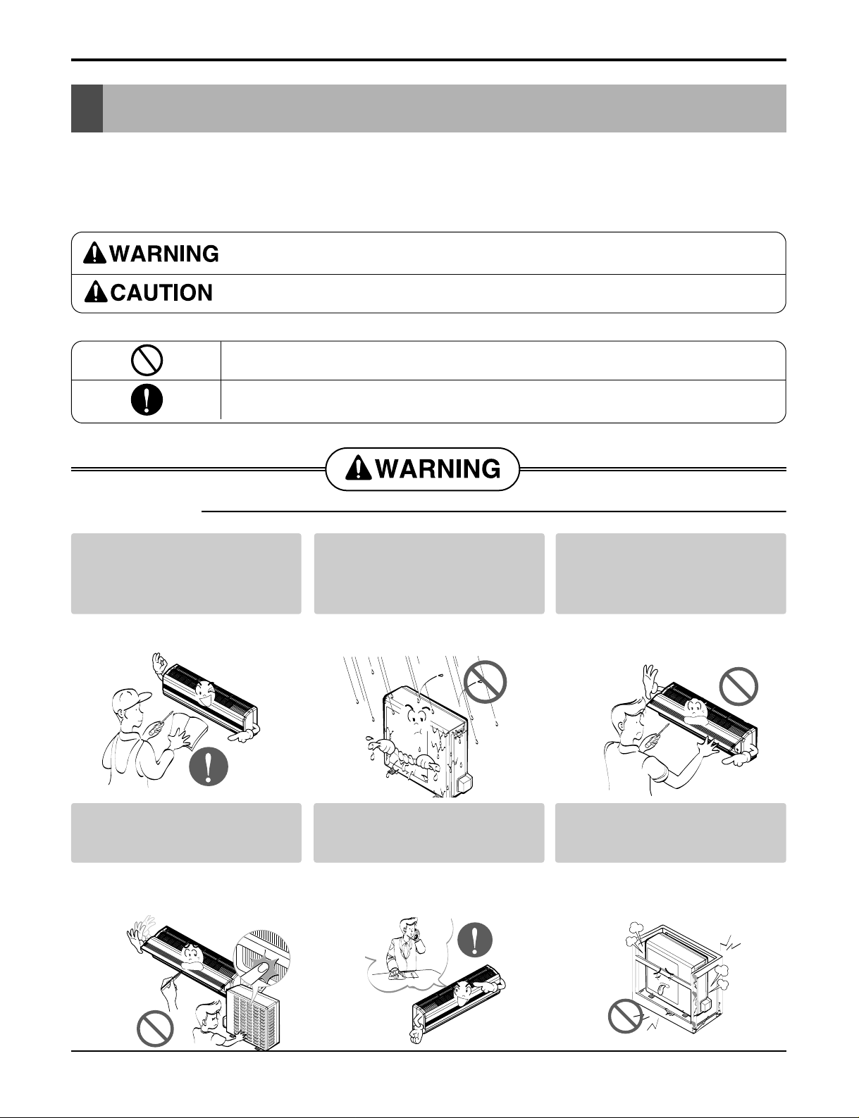
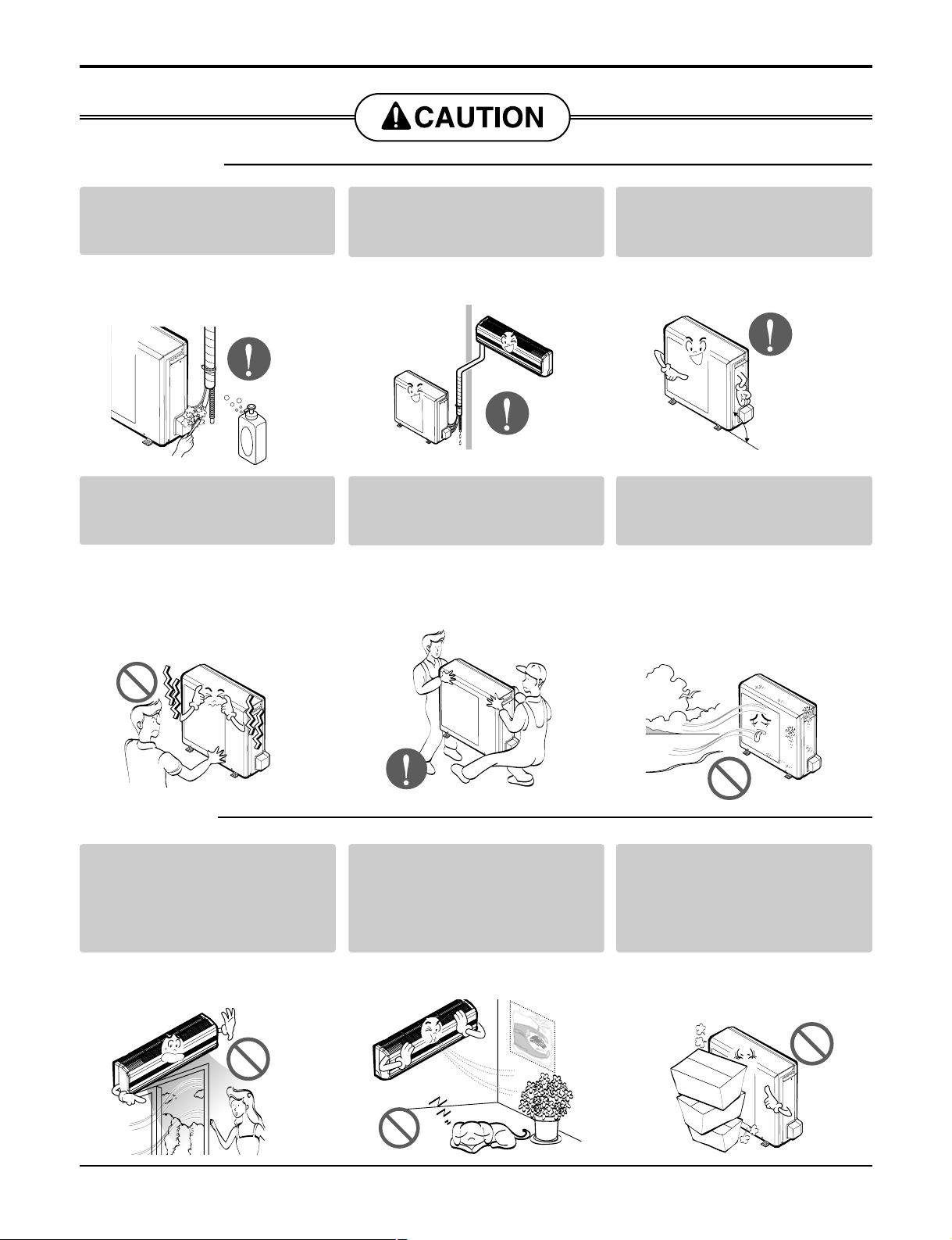
Safety Precautions
Safety Precautions
To prevent injury to the user or other people and property damage, the following instructions must
be followed.
■ Incorrect operation due to ignoring instruction will cause harm or damage. The seriousness is
classified by the following indications.
■ Meanings of symbols used in this manual are as shown below.
This symbol indicates the possibility of death or serious injury.
This symbol indicates the possibility of injury or damage to properties only.
Be sure not to do.
Be sure to follow the instruction.
■ Installation
For electrical work, contact the
dealer, seller, a qualified electrician, or an Authorized Service
Center.
• There is risk of fire or electric shock.
Install the panel and the cover of
control box securely.
• There is risk of fire or electric shock.
Do not install, remove, or re-install
the unit by yourself (customer).
• There is risk of fire, electric shock,
explosion or injury.
Be cautious when unpacking and
installing the product.
• Shape edges could cause injury. Be
especially careful of the sharp
edges.
For installation, always contact the
dealer or an Authorized Service
Center.
• There is risk of fire, electric shock,
explosion, or injury.
Do not install the product on a
defective installation stand.
• It may cause injury, accident, or
damage to the product.
Page 4
4 Room Air Conditioner
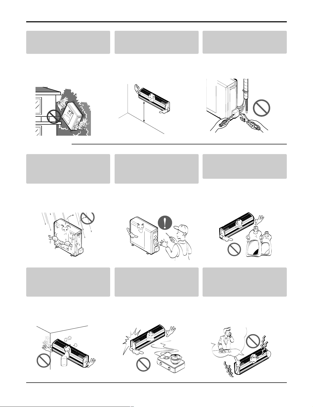
Safety Precautions
■ Operation
Be sure the installation area does
not deteriorate with age.
• If the base collapses, the air conditioner could fall with it, causing property damage, product failure, and
personal injury.
Install the indoor unit on the wall
where the height from the floors
more than 8ft(2.4m)
• There are sharp moving parts that
could cause personal injury.
Do not handle the pipe by yourself(Costomer)
• High-Pressure refrigent may cause
personal injury.
Do not allow water to run into
electric part.
• There is risk of fire, failure of the
product, and/or electric shock.
Do not let the air conditioner run
for a long time when the humidity
is very high and a door or a window is left open.
• Moisture may condense and wet or
damage furnishings.
Do not store or use flammable gas
or combustibles near the air conditioner.
• There is risk of fire or product failure.
Do not use the product in a tightly
closed space for a long time.
• Oxygen deficiency could occur.
•
Some ventilation by opening window is
necessary for the fresh air
When flammable gas leaks, turn off the gas
and open a window for ventilation before
turning the product on. Do not use the telephone or turn switches on or off.
• There is risk of explosion or fire.
Turn off breaker to the unit if
strange sounds odors or smoke
comes from it.
•
There is risk of fire, Product faiure,
and/or electric shock.
8ft(2.4m)
Wax
Thinner
Page 5
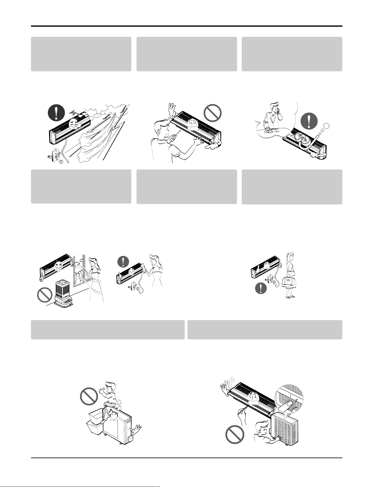
Service Manual 5
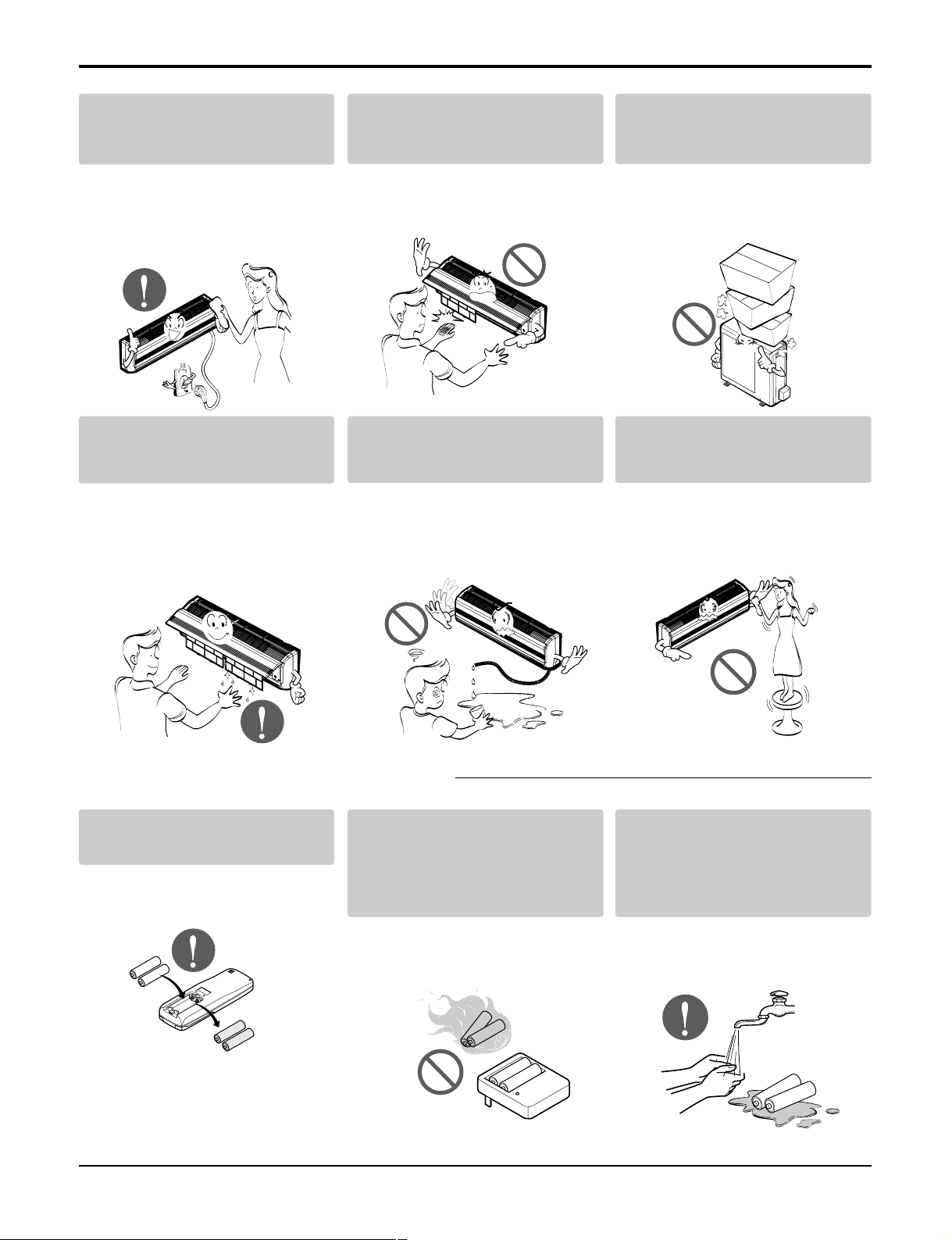
Safety Precautions
Stop operation and close any window in storm or hurricane before
the hurricane arrives.
• There is risk of property damage,
failure of product, or electric shock.
Do not open the inlet grill of the
product during operation. (Do not
touch the electrostatic filter, if the
unit is so equipped.)
• There is risk of physical injury, electric shock, or product.
When the product is soaked (flooded or submerged), contact an
Authorized Service Center.
• There is risk of electrical shock.
Ventilate the product from time to
time when operating it together
with a stove, etc.
• There is risk of fire or electrical
shock.
Turn off breaker to the appliance
before performing cleaning or
maintenance.
• There is risk of electric shock.
When the product is not be used
for a long time disconnect the
power supply by turning off the
breaker.
• There is risk of product damage or
failure, or unintended operation.
Take care to ensure that nobody could step on or fall
onto the outdoor unit.
• There could result in personal injury and product damage.
Do not insert hands or other objects through the air
inlet or outlet while the air conditioner is on.
• There are sharp and moving parts that could cause personal injury.
Page 6
6 Room Air Conditioner
Safety Precautions
Always check for gas(refrigerant)
leakage after installation or repair
of product.
• Low refrigerant levels may cause
product failure.
Install the drain hose to ensure that
water is drained away properly.
• A bad connection may cause water
leakage.
Keep level even when installing the
product.
• To avoid vibration or water leakage.
Do not install the product where
the noise or hot air from the outdoor unit could offend neighbors.
• It may cause a problem for your
neighbors.
Use two or more people to lift and
transport the air conditioner.
• Avoid personal injury.
Do not install the product where it
will be exposed to sea wind (salt
spray) directly.
• It may cause corrosion in the product. Corrosion, particularly on the
condenser and evaporator fins,
could cause product malfunction or
inefficient operation.
Do not direct airflow at room occupants.
• This could damage your health.
Do not use the product for special
purposes, such as preserving foods,
works of art, etc. It is a consumer air
conditioner, not a precision refrigeration system.
• There is risk of damage or loss of
property.
Do not block the inlet or outlet of
air flow.
• It may cause product failure.
■ Installation
■ Operation
90˚
Page 7
Service Manual 7
Safety Precautions
Use a soft cloth to clean.
Do not use harsh detergents, solvents, etc.
• There is risk of fire, electric shock or
damage to the plastic parts of the
product.
Do not touch the metal parts of the
product when removing the air filter. They are very sharp!
• There is risk of personal injury.
Do not step on or put anything on
the product. (outdoor unit)
• There is risk of personal injury and
failure of product.
Always insert the filter securely.
Clean the filter every two weeks or
more often if necessary.
• A dirty filter reduces the efficiency of
the air conditioner and could cause
product malfunction or damage.
Do not drink the water drained from
the unit.
• It is not sanitary and could cause
serious health issues.
Use a firm stool or ladder when
cleaning or maintaining the air conditioner.
• Be careful and avoid personal injury.
Replace all the batteries in the
remote.
• There is risk of fire or explosion.
Do not recharge or disassemble
the batteries. Do not dispose of
batteries in a fire.
• They may burn or explode.
If the liquid from the batteries gets
onto your skin or clothes, wash it
well with clean water. Do not use
the remote if the batteries have
leaked.
• The chemicals in batteries could
cause burns or other health hazards.
■ Disuse
Page 8
8 Room Air Conditioner
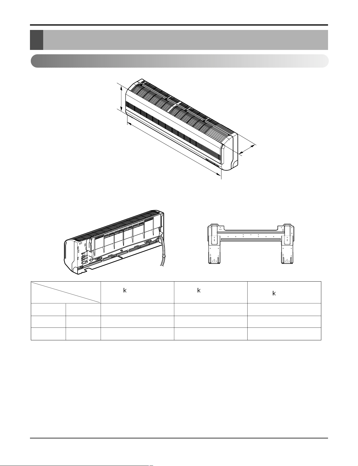
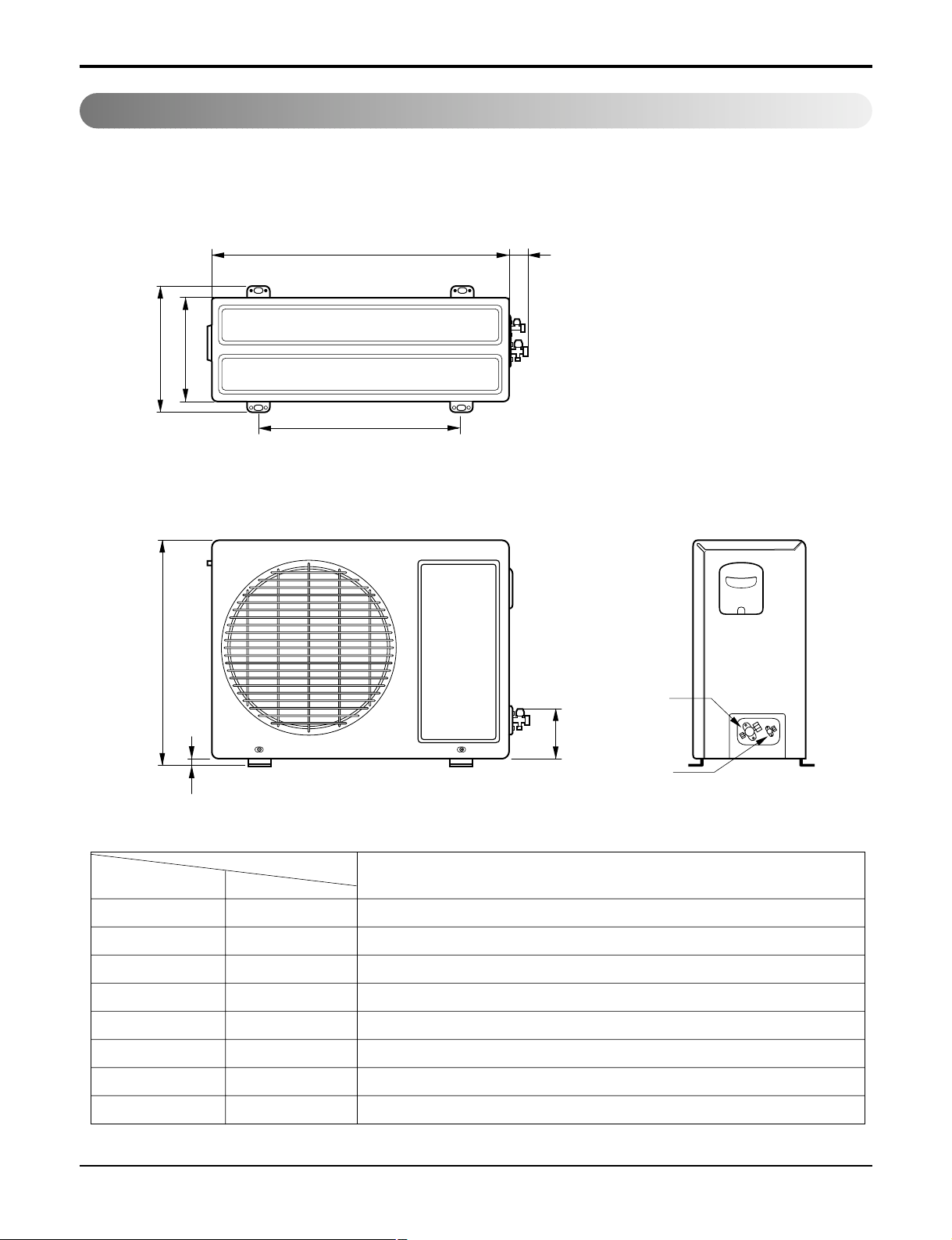
Dimensions
Dimensions
D
H
W
Installation plate
W mm(inch) 840(33.1) 894(35.2) 894(35.2)
H mm(inch) 270(10.6) 295(11.6) 295(11.6)
D mm(inch) 153(6.0) 165(6.5) 165(6.5)
Model
Dimension
9 Btu Series
(C/O)
9 Btu Series
(H/P)
12
Btu Series
Indoor Unit
Page 9
Service Manual 9
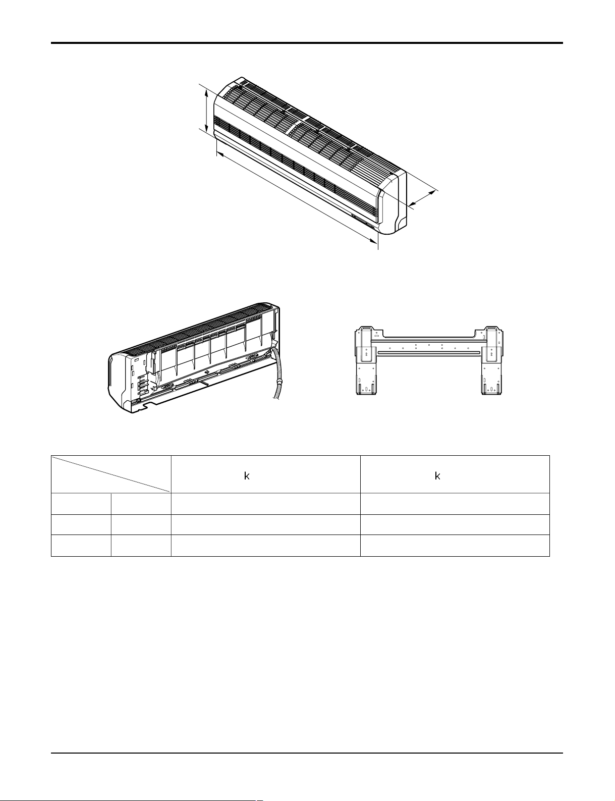
Dimensions
D
H
W
Installation plate
W mm(inch) 1090(42.9) 1090(42.9)
H mm(inch) 300(11.8) 300(11.8)
D mm(inch) 178(7.0) 178(7.0)
Model
Dimension
18 Btu Series 24 Btu Series
Page 10
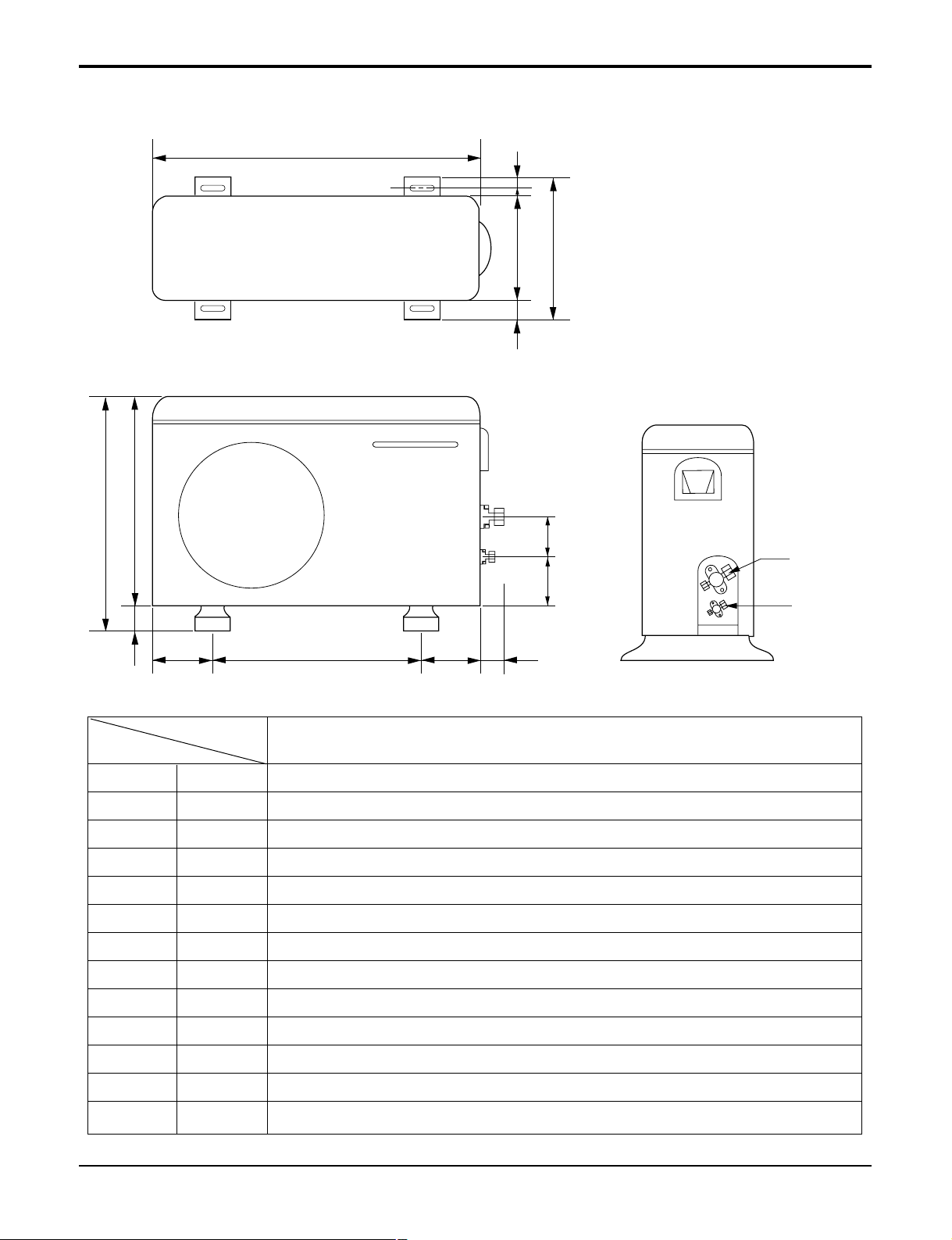
10 Room Air Conditioner
Dimensions
Outdoor Unit
1. 9k, 12k
W
L2
L3
L1
D
H
L4
L5
Gas side
(3-way valve)
Liquid side
(2-way valve)
MODEL
9k, 12k
DIM unit
W mm(inch) 770(30.3)
H mm(inch) 540(21.3)
D mm(inch) 245(9.6)
L1 mm(inch) 287(11.3)
L2 mm(inch) 64(2.5)
L3 mm(inch) 518(20.4)
L4 mm(inch) 10(0.4)
L5 mm(inch) 100(3.9)
Page 11
Service Manual 11
Dimensions
2. 18k, 24k
W
L6 L5 L7 L8
D
L1
L2
L9L10
L3L4
H
MODEL
18k, 24k
DIM
W mm(inch) 870(34.3)
H mm(inch) 655(25.8)
D mm(inch) 320(12.6)
L1 mm(inch) 370(14.6)
L2 mm(inch) 25(1.0)
L3 mm(inch) 630(24.8)
L4 mm(inch) 25(1.0)
L5 mm(inch) 546(21.5)
L6 mm(inch) 162(6.4)
L7 mm(inch) 162(6.4)
L8 mm(inch) 54(2.1)
L9 mm(inch) 74.5(2.9)
L10 mm(inch) 79(3.1)
Page 12
12 Room Air Conditioner
Introduction
Introduction
This symbol alerts you to the risk of electric shock.
This symbol alerts you to hazards that may cause harm to the air conditioner.
This symbol indicates special notes.
NOTICE
Symbols Used In This Manual
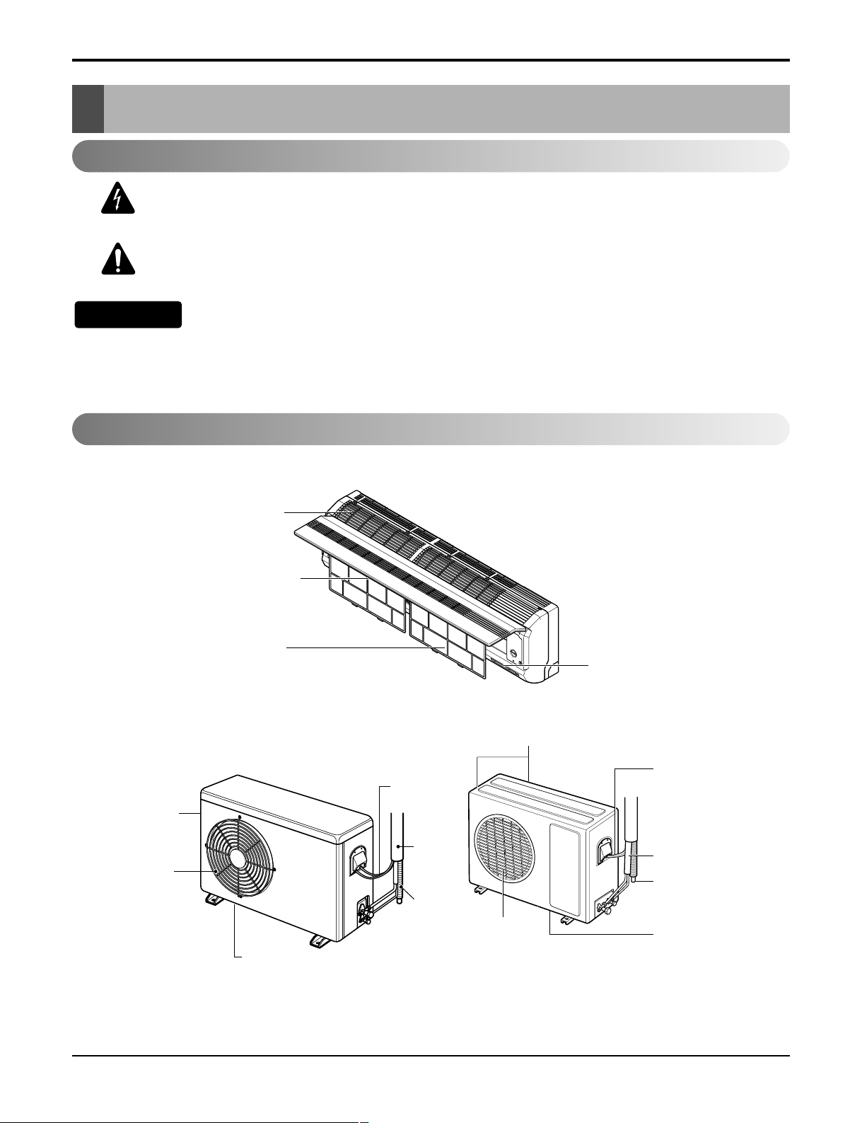
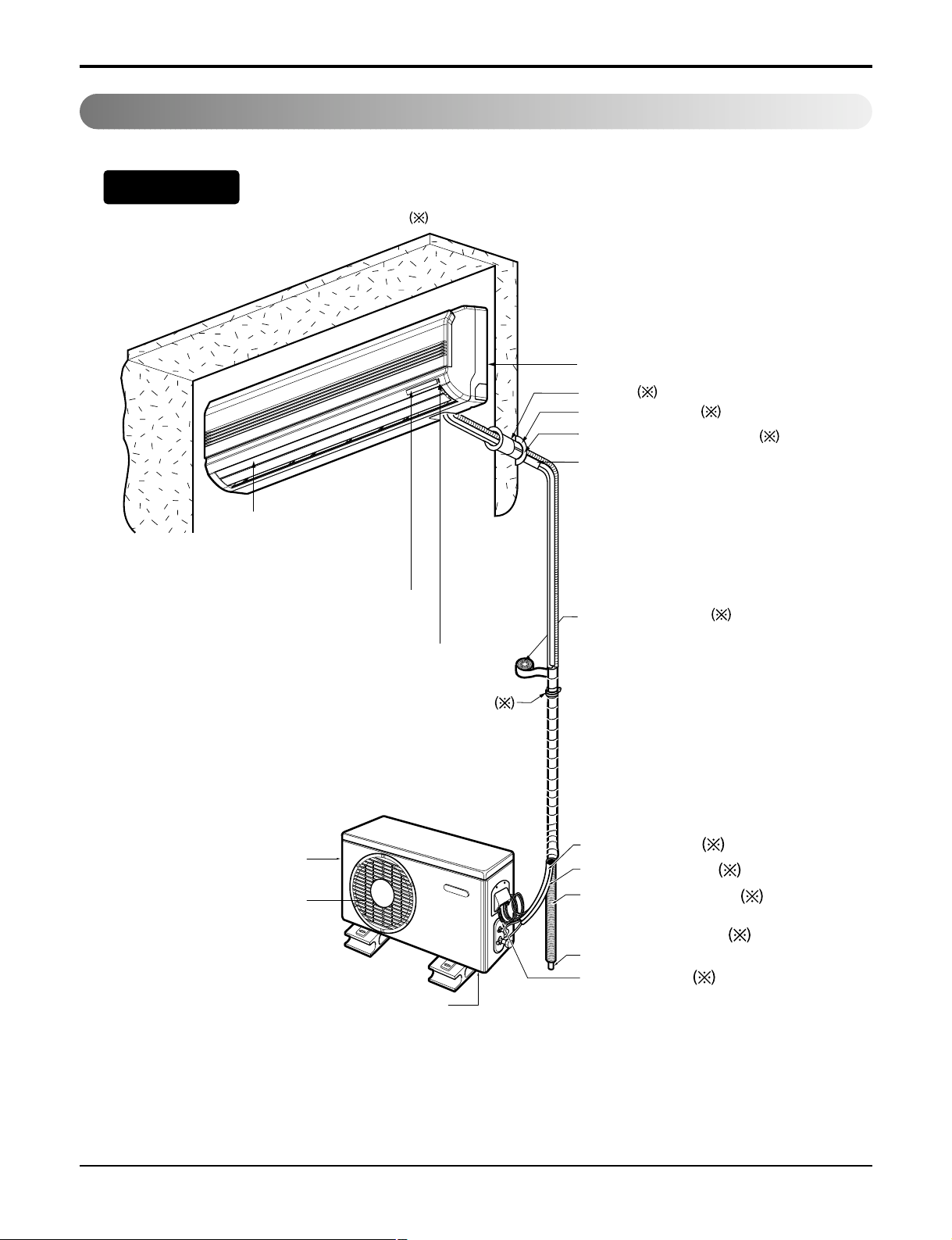
Features
Air Intake Vents
Air Outlet Vents
Connecting
Wires
Piping
Drain Hose
Base Plate
Air Outlet
Vents
Air Intake
Vents
Piping
Connecting
Wires
Drain Hose
Base Plate
Air Inlet
Front Panel
Air Filter
Signal Receptor
Page 13
Service Manual 13
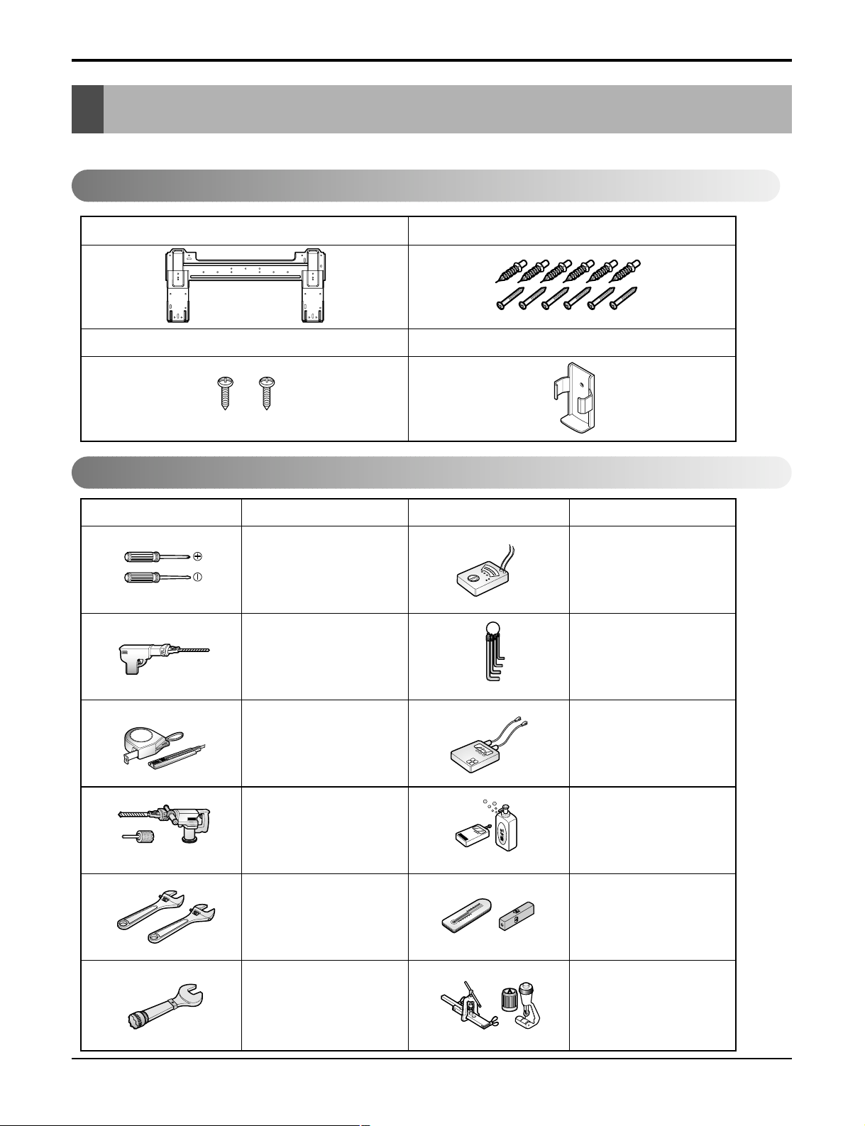
Introduction
Type "A" screw and plastic anchor
Type "B" screw
Remote Control Holder
Installation plate
Figure FigureName
Screw driver
Electric Drill
Measuring Tape, Knife
Hole Core Drill
Spanner
Torque wrench
Ohmmeter
Hexagonal wrench
Ammeter
Gas Leak Detector
Thermometer,
Level
Flaring Tool Set
Name
Installation Parts
Installation Tools
Read carefully, and then follow step by step.
Installation
Page 14
14 Room Air Conditioner
Installation
Installation Map
Base Plate
Air Inlet Vents
Air Outlet Vents
Installation parts you should purchase.
Air Discharge
Forced Operation Button
Operation Indication Lamps/
Signal Receptor
Vinyl tape (Wide)
• Apply after carrying out a
drainage test.
• To carry out the drainage
test, remove the air filters
and pour water into the heat
exchanger.
Saddle
Gas side piping (Optional Parts)
Liquid side piping (Optional Parts)
Additional drain pipe
Vinyl tape (Narrow)
Drain Hose
Connecting cable
(Optional Parts)
Installation plate
Sleeve
Bushing-Sleeve
Putty(Gum Type Sealer)
Bend the pipe as closely
on the wall as possible,
but be careful that it
doesn't break.
NOTICE
Page 15

Service Manual 15
Installation
1. Check the quality label on the indoor and outdoor unit.
2. Make certain that the refrigerant is R-410A.
THIS PRODUCT CONTAINS R-410A REFRIGERANT
1) Different compressor oil
- R-410A(Polyol ester) / R-22(Mineral).
- Do not mix the existing mineral oil.
- Do not apply used pipe, tools and gauges covered with the existing mineral oil.
2) Absorption of moisture
-Compressor’s oil has the high absorption rate of moisture.
3) Composition
- R-410A(R32:R125=50:50wt%).
NOTE: Never mix with other refrigerants
4) High pressure.
- 1.6 times higher than R-22.
- High Pressure refrigerant may cause personal injury.
Do not handle the pipe by yourself (customer) High-pressure refrigerant may cause personal injury.
- manifold gauge ,charging and any piping tools must be dedicated to R-410A systems.
NOTICE
Confirm The Refrigerant
Page 16
16 Room Air Conditioner
Outdoor unit
1. If an awning is built over the unit to prevent
direct sunlight or rain exposure, make sure that
heat radiation from the condenser is not
restricted.
2. Ensure that the space around the back and
sides is more than 10cm(3.9in). The front of the
unit should have more than 70cm(27.6in) of
space.
3. Do not place animals and plants in the path of
the warm air.
4. Take the air conditioner weight into account and
select a place where noise and vibration are
minimum.
5. Select a place so that the warm air and noise
from the air conditioner do not disturb neighbors.
Rooftop Installations
If the outdoor unit is installed on a roof structure, be sure to level the unit. Ensure the roof structure and
anchoring method are adequate for the unit location. Consult local codes regarding rooftop mounting.
If the outdoor unit is installed on roof structures or walls, this may result in excessive noise and vibration, and may be also classed as non serviceable installation.
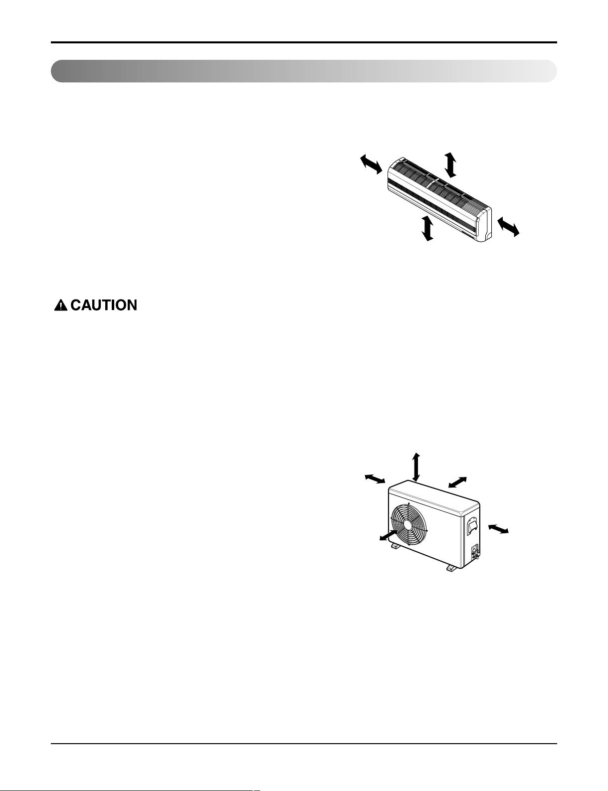
Indoor unit
1. Do not have any heat or steam near the unit.
2. Select a place where there are no obstacles in
front of the unit.
3. Make sure that condensation drainage can be
conveniently routed away.
4. Do not install near a doorway.
5. Ensure that the space around the left and right
of the unit is more than 30cm(11.8in). The unit
should be installed as high on the wall as possible, allowing a minimum of 12cm(4.7in) from
ceiling.
6. Use a stud finder to locate studs to prevent
unnecessary damage to the wall.
Select The Best Location
Install the indoor unit on the wall where the height from the floors more than 2.3meters(7.6ft).
A minimum pipe run of 7.5meters(24.6ft) is required to minimize vibration and excessive noise.
More than
12cm(4.7in)
More than
30cm(11.8in)
More than
30cm(11.8in)
More than 2.4meters(8ft)
More than
10cm(3.9in)
More than
10cm(3.9in)
More than
60cm(23.6in)
More than
60cm(23.6in)
More than
70cm(27.6in)
Installation
Page 17
Service Manual 17
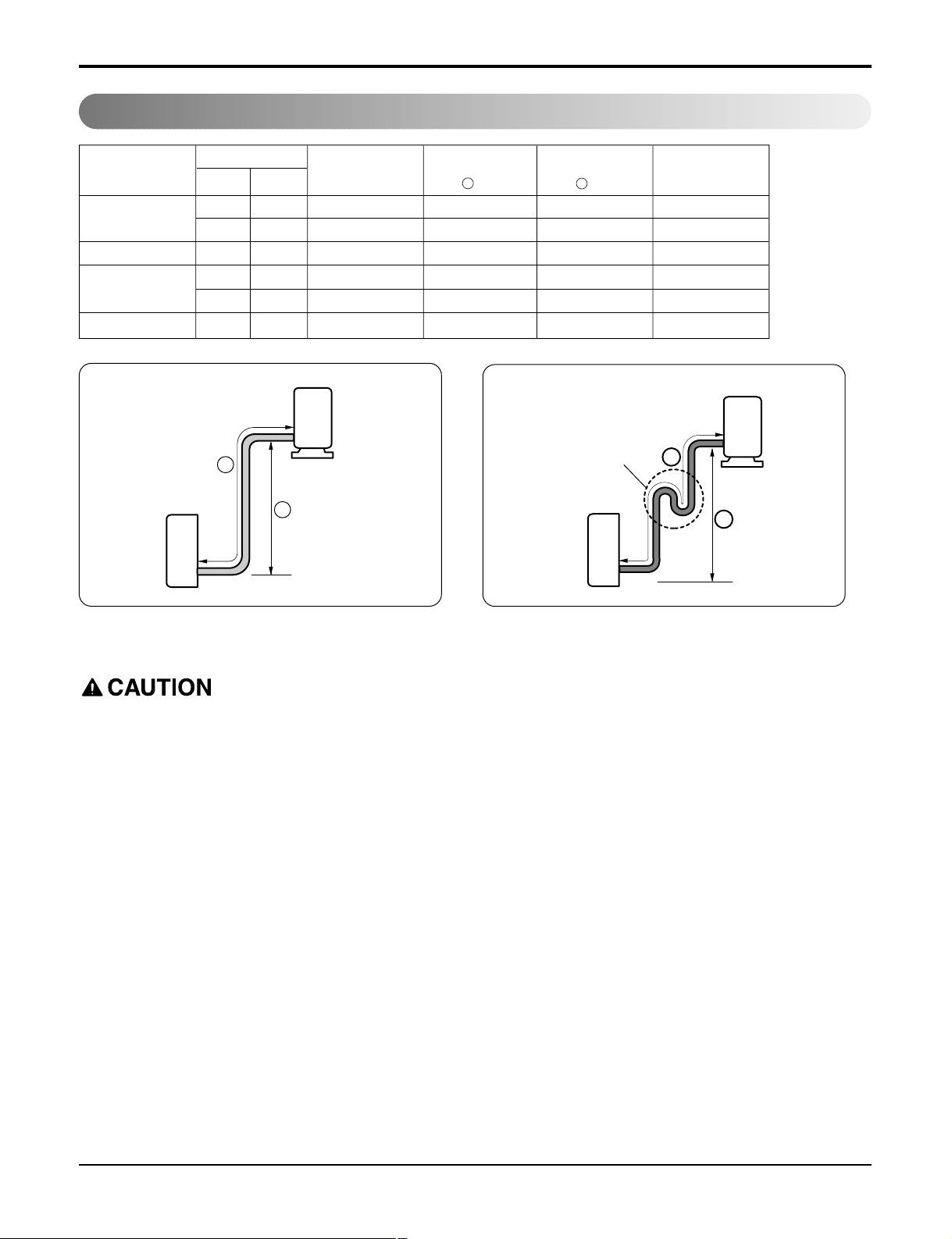
Piping Length And Elevation
• Capacity is based on standard length and maximum allowance length is on the basis of reliability.
• Oil trap should be installed every 5~7meters (16.4~23.0ft).
In case more than 5m(16.4ft)
Outdoor unit
Indoor unit
A
B
A
Oil trap
Outdoor unit
Indoor unit
B
Pipe Size
Capacity
(Btu/h)
Suction
Evap
Max.
length
A
m(ft)
Additional Refrigerant
g/m(oz/ft)
Max.
Elevation
B m(ft)
Standard
Length
m(ft)
9k
3/8" 1/4" 7.5(25) 7.5(25) 15(49) 20(0.22)
1/2" 1/4" 7.5(25) 7.5(25) 15(49) 20(0.22)
12k 1/2" 1/4" 7.5(25) 7.5(25) 15(49) 20(0.22)
18k
1/2" 1/4" 7.5(25) 15(49) 30(98) 20(0.22)
5/8" 1/4" 7.5(25) 7.5(25) 15(49) 20(0.22)
24k 5/8" 1/4" 7.5(25) 7.5(25) 15(49) 20(0.22)
Installation
Page 18
18 Room Air Conditioner
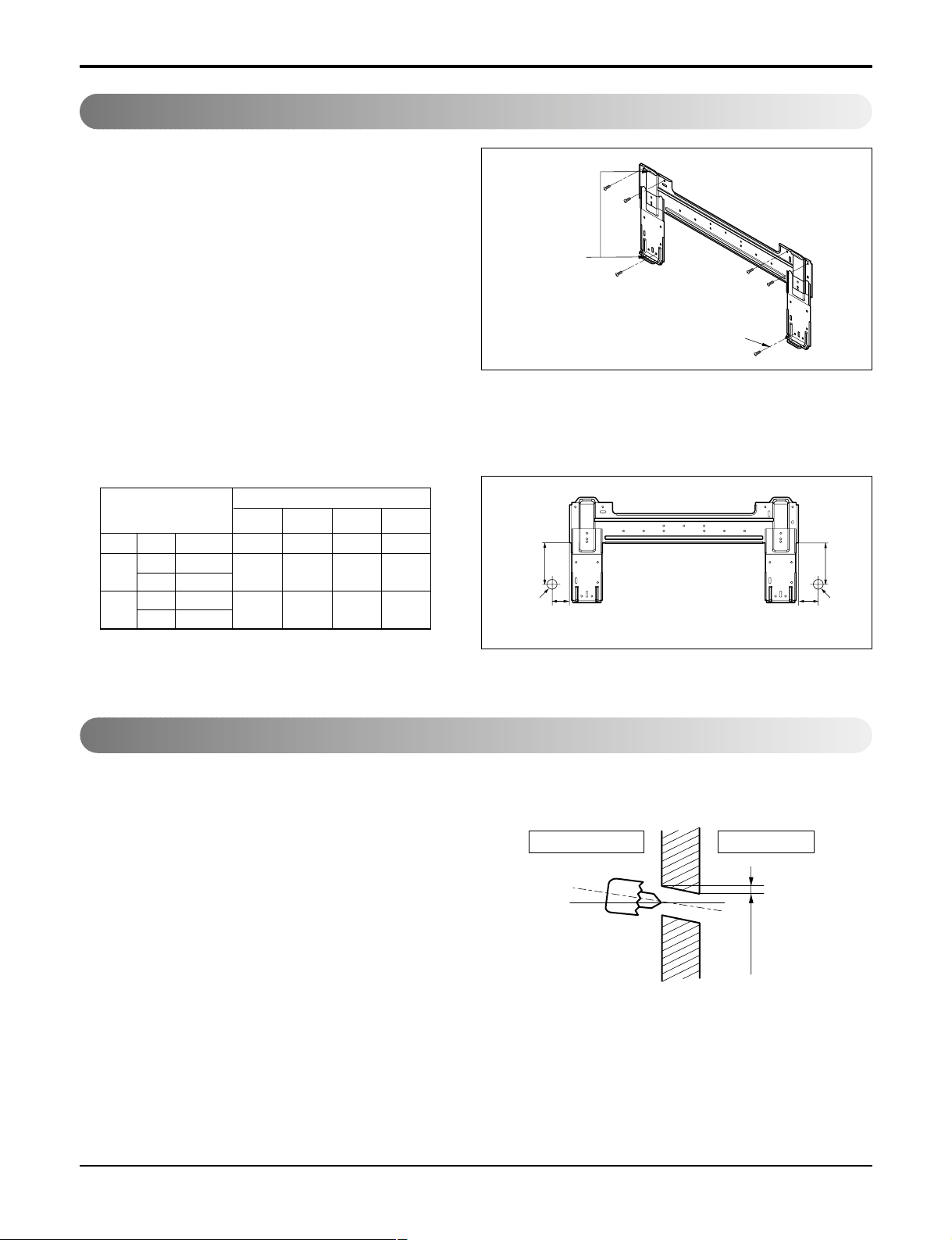
The wall you select should be strong and solid enough
to prevent vibration
1. Mount the installation plate on the wall with
type "A" screws. If mounting the unit on a concrete
wall, use anchor bolts.
• Mount the installation plate horizontally by aligning the
centerline using a level.
How To Mount Installation Plate
Chassis
Hook
Installation Plate
Type “A”
• Drill the piping hole with a ø70mm(2.76in) hole
core drill. Drill the piping hole at either the right
or the left with the hole slightly slanted to the outdoor side.
Drill a Hole In The Wall
5-7mm
(0.2~0.3")
Indoor
WALL
Outdoor
2. Measure the wall and mark the centerline. It is also important to use caution concerning the location of the installation plate-routing of the wiring to power outlets is through the walls typically. Drilling the hole through the wall
for piping connections must be done safely.
Installation plate
Left rear piping Right rear piping
Ø70mm
Ø70mm
D
B
A
C
S4 9k C/O 1.97 4.13 2.32 4.13
SE
9k H/P
2.56 4.33 3.35 4.33
12k C/O, H/P
S5
18k C/O, H/P
3.74 4.80 9.25 4.80
24k C/O, H/P
CHASSIS
(Grade)
Distance (inch)
ABCD
Installation
Page 19
Service Manual 19
Flaring Work
Cut the pipes and the cable.
1. Use the piping kit accessory or the pipes purchased
locally.
2. Measure the distance between the indoor and the out-
door unit.
3. Cut the pipes a little longer than measured distance.
4. Cut the cable 1.5m(59.1in) longer than the pipe length.
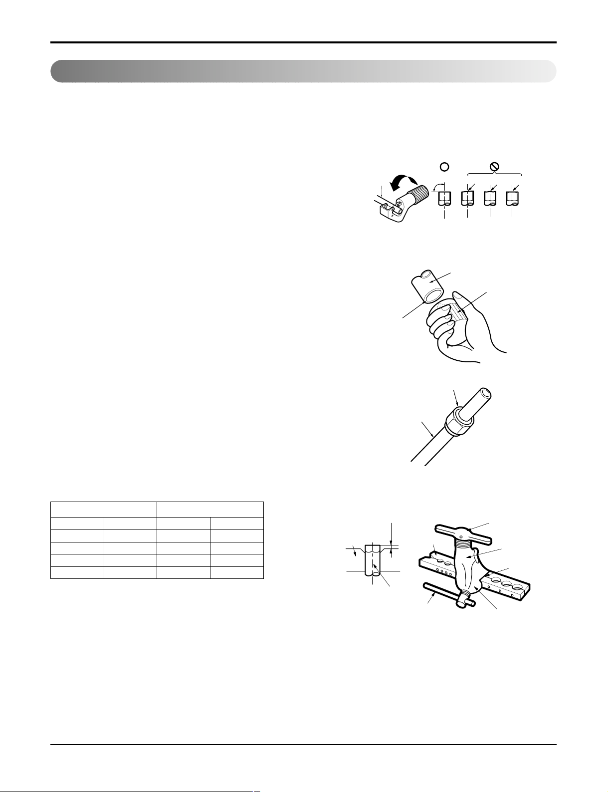
Burrs removal
1. Completely remove all burrs from the cut cross section
of pipe/tube.
2. Put the end of the copper tube/pipe in a downward
direction as you remove burrs in order to avoid dropping burrs into the tubing.
Putting nut on
• Remove flare nuts attached to indoor and outdoor unit,
then put them on pipe/tube having completed burr
removal.
(not possible to put them on after flaring work)
Flaring work
• Carry out flaring work using flaring tool as shown below.
Main cause for gas leakage is due to defect in flaring work. Carry out correct flaring work in the following procedure.
Bar
Copper pipe
Clamp handle
Red arrow mark
Cone
Yoke
Handle
Bar
"A"
Pipe
Reamer
Point down
Copper
pipe
90°
Slanted Uneven Rough
Firmly hold copper pipe in a die in the dimension shown in the table abov e .
Flare nut
Copper tube
mm inch mm inch
Ø6.35 1/4 0~0.5 0~0.020
Ø9.52 3/8 0~0.5 0~0.020
Ø12.7 1/2 0~0.5 0~0.020
Ø15.88 5/8 0~1.0 0~0.039
Outside diameter A
Installation
Page 20
20 Room Air Conditioner
Indoor
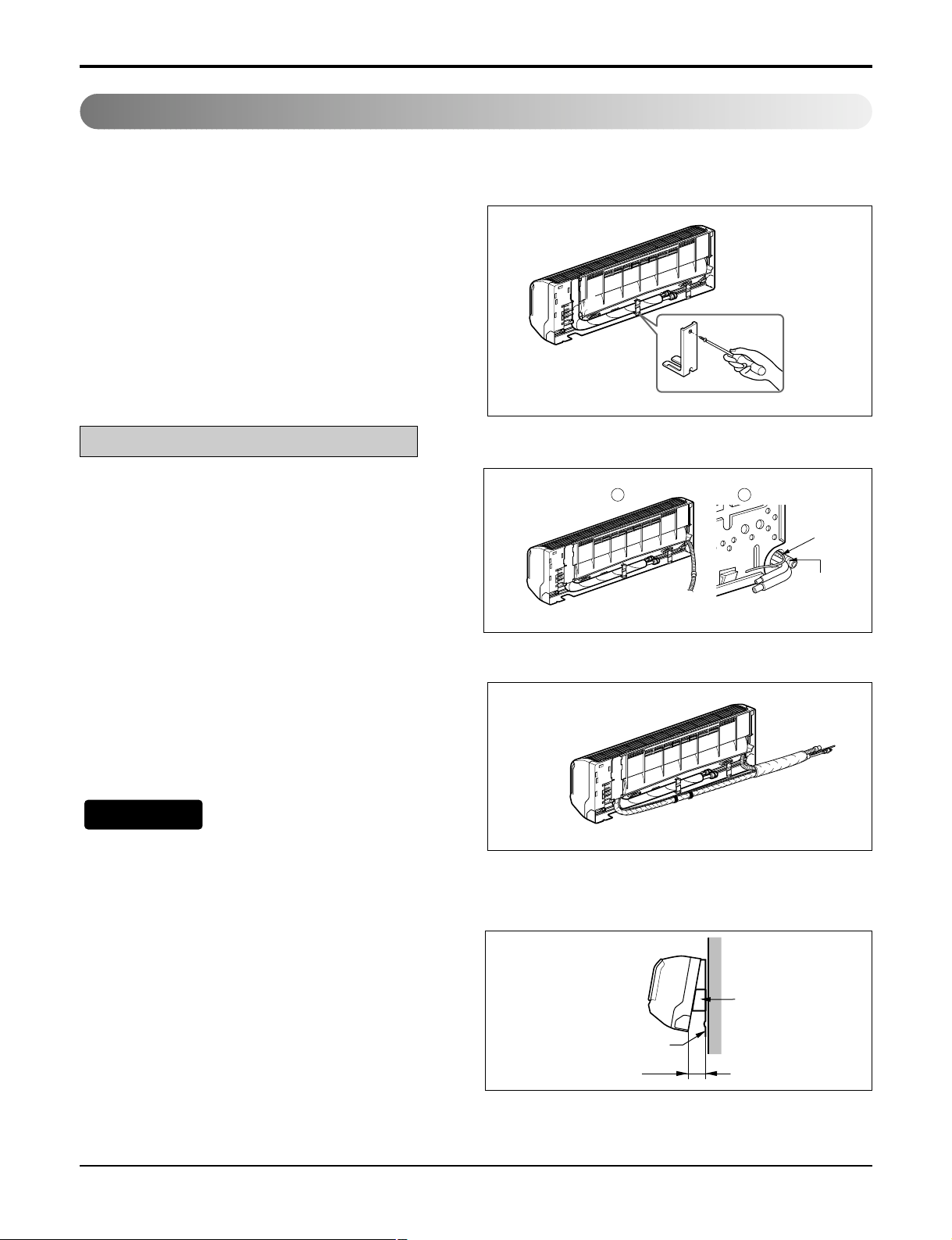
1. Prepare the indoor unit's piping and drain hose for installation through the wall.
2. Remove the plastic tubing retainer(see the illus-
tration by) and pull the tubing and drain hose
away from chassis.
3. Replace only the plastic tubing holder 1, not the
holder 2 in the original position.
Route the indoor tubing and the drain
hose in the direction of rear left.
Insert the connecting cable into the indoor unit
from the outdoor unit through the piping hole.
• Do not connect the cable to the indoor unit.
• Make a small loop with the cable for easy con-
nection later.
Tape the tubing, drain hose and the connecting
cable. Be sure that the drain hose is located at the
lowest side of the bundle. Locating at the upper
side can cause drain pan to overflow inside the
unit.
If the drain hose is routed inside the room, insulate the hose with an insulation material* so that
dripping from "sweating"(condensation) will not
damage furniture or floors.
*Foamed polyethylene or equivalent is recom-
mended.
Indoor unit installation
• Hook the indoor unit onto the upper portion of
the installation plate.(Engage the three hooks of
the rear top and rear lower of the indoor unit with
the upper edge and lower edge of the installation
plate.) Ensure that the hooks are properly seated
on the installation plate by moving it left and
right.
NOTICE
Connecting The Piping
For left rear piping
Installation
1 2
Connecting
cable
Drain pipe
Indoor unit
Spacer
Installation plate
8cm
Page 21
Service Manual 21
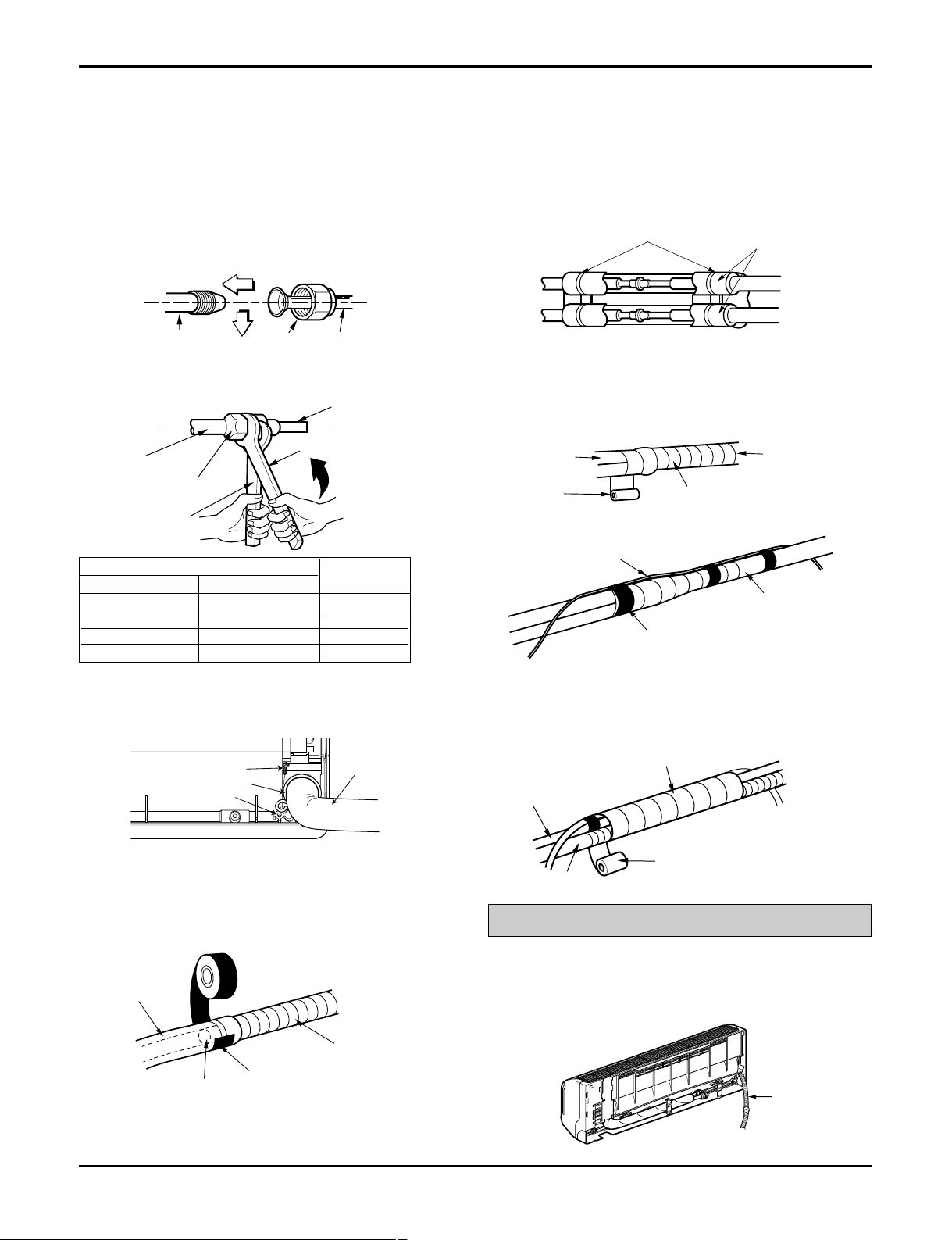
Wrap the insulation material around the
connecting portion.
• Overlap the connection pipe insulation material
and the indoor unit pipe insulation material. Bind
them together with vinyl tape so that there is no
gap.
Route the indoor tubing and the drain
hose to the required piping hole position.
Plastic bands
Insulation material
Connection pipe
Flare nut
Indoor unit tubing
Torque wrench
Spanner (fixed)
Vinyl tape(narrow)
Adhesive
Drain pipe
Indoor unit drain hose
• When extending the drain hose at the indoor
unit, install the drain pipe.
• Tighten the flare nut with a wrench.
For right rear piping
Connecting the pipings to the indoor unit
and drain hose to drain pipe.
• Put a couple drops of refrigerant oil on the face
of the flare before assembling taking care not to
add any contaminants.
• Align the center of the pipings and sufficiently
tighten the flare nut by hand.
Indoor unit tubing Flare nut Pipings
Drain hose
Ø6.35 1/4 13.0
Ø9.52 3/8 30.4
Ø12.7 1/2 39.8
Ø15.88 5/8 47.7
Outside diameter
mm inch
Torque
Vinyl tape(narrow)
Connection
pipe
Connecting cable
Vinyl tape
(wide)
Wrap with vinyl tape
Indoor
unit pipe
Pipe
• Bundle the piping and drain hose together by
wrapping them with vinyl tape over the range
within which they fit into the rear piping housing
section.
Wrap with vinyl tape
Drain hose
Pipe
Vinyl tape(wide)
• Wrap the area which accommodates the rear piping
housing section with vinyl tape.
• Mount the clamp on the boss with a type "B"
screw.(SE-H/P: 9k, 12k C/O: 12k)
Installation
Type "B" screw
Clamp
Boss
Drain hose
Page 22
22 Room Air Conditioner
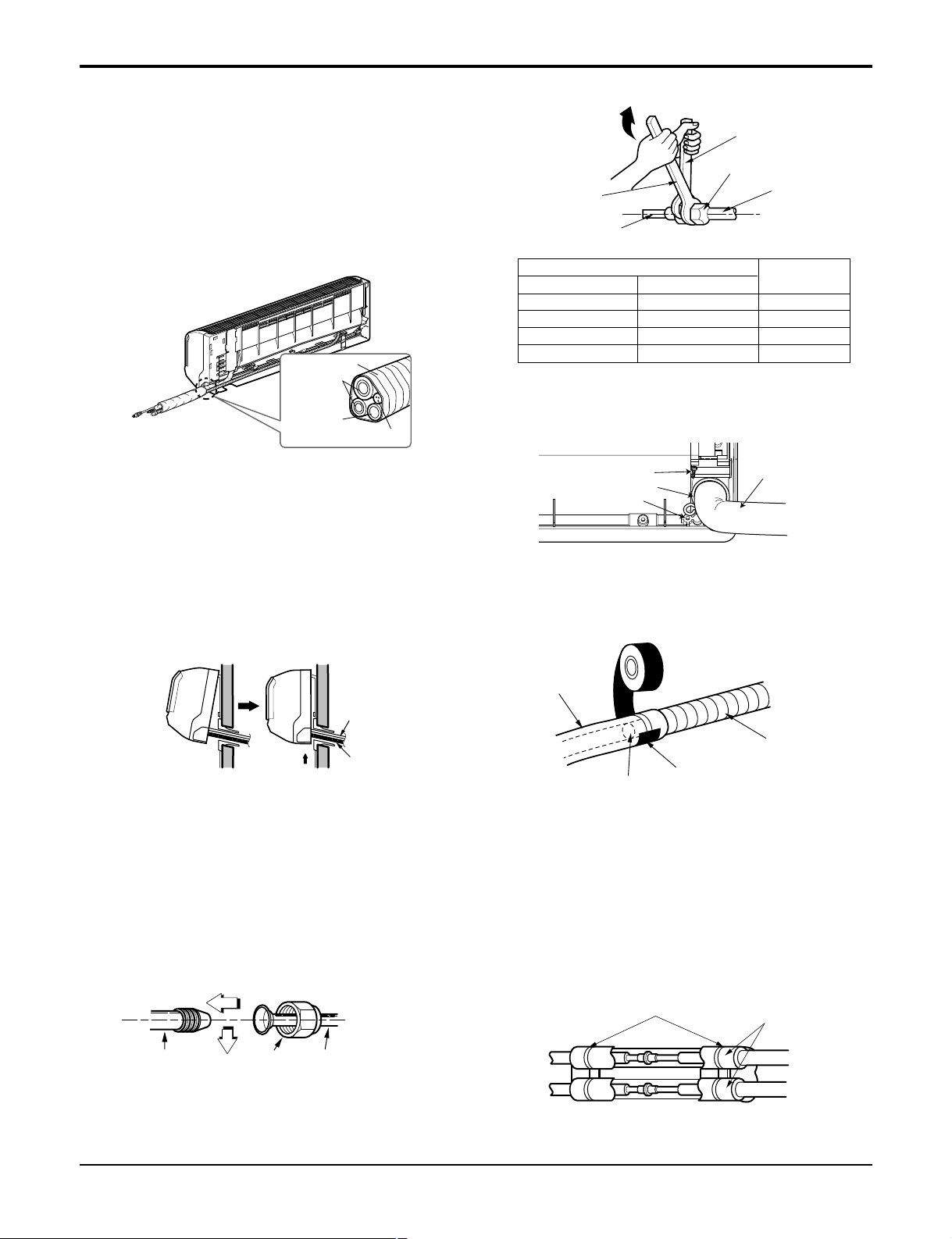
Insert the connecting cable into the indoor
unit.
• Don't connect the cable to the indoor unit.
• Make a small loop with the cable for easy con-
nection later.
Tape the drain hose and the connecting cable.
• Connecting cable
Connecting the pipings to the indoor unit
and the drain hose to drain pipe.
• Put a couple drops of refrigerant oil on the face
of the flare before assembling taking care not to
add any contaminants
• Align the center of the pipings and sufficiently
tighten the flare nut by hand.
• Tighten the flare nut with a wrench.
Indoor unit tubing Flare nut Pipings
Torque wrench
Indoor unit tubing
Spanner (fixed)
Connection pipe
Flare nut
Indoor unit installation
• Hook the indoor unit onto the upper portion of
the installation plate.(Engage the three hooks of
the rear top and rear lower of the indoor unit with
the upper edge and lower edge of the installation
plate.) Ensure that the hooks are properly seated
on the installation plate by moving it left and
right.
Vinyl tape
Adhesive
Drain hose
Indoor unit drain hose
(narrow)
• When extending the drain hose at the indoor
unit, install the drain pipe.
Connecting
pipe
Connecting cable
Tape
Drain hose
Drain hose
Connecting
cable
• Mount the clamp on the boss with a type "B"
screw.(SE-H/P: 9k, 12k C/O: 12k)
Wrap the insulation material around the
connecting portion.
• Overlap the connection pipe heat insulation and
the indoor unit pipe heat insulation material.
Bind them together with vinyl tape so that there
is no gap.
Plastic bands
Insulation material
Ø6.35 1/4 13.0
Ø9.52 3/8 30.4
Ø12.7 1/2 39.8
Ø15.88 5/8 47.7
Outside diameter
mm inch
Torque
(lbf.ft)
Installation
Type "B" screw
Clamp
Boss
Drain hose
Page 23

Service Manual 23
Reroute the pipings and the drain hose
across the back of the chassis.
Reroute the pipings and the drain hose
across the back of the chassis.
Drain hose
Vinyl tape(narrow)
Pipe
Wrap with
vinyl tape(wide)
• Bundle the piping and drain hose together by
wrapping them with cloth tape over the range
within which they fit into the rear piping housing
section.
Piping for
passage through
piping hole
Drain hose
Connecting
cable
• Wrap the area which accommodates the rear
piping housing section with vinyl tape.
Vinyl tape(narrow)
Connection
pipe
Connecting cable
Indoor
unit piping
Pipe
Vinyl tape
(wide)
Wrap with vinyl tape
Installation
Page 24

24 Room Air Conditioner
Installation Information. For left piping. Follow the instruction below.
Correct case
• Press on the upper side of clamp and unfold the tubing to downward slowly.
Incorrect case
• Following bending type from right to left may cause damage to the tubing.
Installation
Page 25

Service Manual 25
Put a couple drops of refrigerant oil on
the face of the flare before assembling
taking care not to add any contaminants.
Align the center of the pipings and sufficiently tighten the flare nut by hand.
• The drain hose can be connected at two different
positions. Use the most convenient position and, if
necessary, exchange the position of the drain pan,
rubber cap and the drain hose.
➊ Drain pan
➋ Rubber cap
➌ Drain hose
➍ Exchange if necessary
• Remove the drain hose.
• Securely insert both the rubber plug and drain hose
into the drain outlets.
Be sure the rubber the cap is securely fastened so
that there is no leakage.
Finally, tighten the flare nut with torque
wrench until the wrench clicks.
• When tightening the flare nut with torque
wrench, ensure the direction for tightening follows the arrow on the wrench.
Outdoor unit
Suction Line piping
(Bigger diameter)
Evaporator Line
piping
(Smaller
diameter)
Torque wrench
1
2
3
4
Connection Of The Drain Hose
Connection Of Piping -Outdoor
Ø6.35 1/4 13.0
Ø9.52 3/8 30.4
Ø12.7 1/2 39.8
Ø15.88 5/8 47.7
Ø19.05 3/4
47.7
Outside diameter
mm inch
Torque
(lbf.ft)
Installation
Page 26

26 Room Air Conditioner
Connection Of The Cable
1
Indoor Unit Outdoor Unit
2
3
4
1
2
3
4
5
6
G
To
branch
circuit
Ground
Power supply
a
L1
*
L2
Connecting cable(Low voltage)
b
Terminal
(4P)
Terminal
(6P)
Outdoor unit
Wiring Diagram
Terminal block
Over 5mm
(0.2")
Cover control
Conduit panel
Connecting
cable
Power supply
cord
*
L1 is neutral for 115V models.
1. Remove the cover control from the unit by
loosening the 3 screws.
2. Dismount caps on the conduit panel.
3. Temporarily mount the conduit tubes on the
conduit panel.
4. Properly connect both the power supply and
low voltage lines to the corresponding terminals on the terminal block.
5. Ground the unit in accordance with local
codes.
6. Be sure to size each wire allowing several
inches longer than the required length for
wiring.
7. Use lock nuts to secure the conduit tubes.
1. shows field wiring.
2. Separately wire the high and low voltage line.
3. Use heat-proof electrical wiring capable of
withstanding temperatures up to 167°F(75°C).
4. Use outdoor and waterproof connection cable
rated more than 300V for the connection
between indoor and outdoor unit.
(For example, Type SJOW)
• Be sure to comply with local codes while
running the wire from the indoor unit to
the outdoor unit(size of wire and wiring
method, etc).
• Every wire must be connected firmly.
• No wire should be allowed to touch refrigerant tubing, the compressor or any moving parts.
Connector trade size for this unit is 1/2" for
instructions on connecting depending on
the wire type you are using.
Power Suppl y
Model
Power source
9k Cooling 1ø, 115V 18 8.6 15
9k Heating 1ø, 115V 14 14.3 20
12k Cooling 1ø, 115V 14 14.3 20
12k Heating 1ø, 115V 14 14.3 20
18k Cooling 1ø, 230/208V 14 13.6 20
18k Heating 1ø, 230/208V 14(12) 17.7 30
24k Cooling 1ø, 230/208V 14(12) 17.7 30
24k Heating 1ø, 230/208V 14(12) 17.7 30
AWG(MIN.)
AWG MCA
MOP(MAXIMUN OVER-
CURRENT PRO TECTION)
NOTICE
NOTICE
Installation
Page 27

Service Manual 27
After the confirmation of the above conditions, prepare the wiring as follows:
1)
Never fail to have an individual power cir cuit specificall y for the air conditioner. As for the
method of wiring, be guided by the circuit diagram posted on the inside of contr ol cover.
2) The screw which fasten the wiring in the casing of electrical fittings are liable to come
loose from vibrations to which the unit is subjected during the course of transportation.
Check them and make sure that they are all tightly fastened. (If they are loose, it could
cause burn-out of the wires.)
3) Specification of power source.
4) Confirm that electrical capacity is sufficient.
5) Confirm that the starting voltage is maintained at more than 90 percent of the rated voltage marked on the name plate.
6) Confirm that the cable thickness is as specified in the power source specification.
(Particularly note the relation between cable length and thickness.
7) Always install an GFCI circuit breaker in a wet or moist area.
8) The following would be caused by voltage drop.
• Vibration of a magnetic switch, which will damage the contact point, open fuse, disturbance of
the normal function of the overload.
9) The means for disconnection from a power supply shall be incorporated in the fixed
wiring and have an air gap contact separation of at least 3mm(0.12in) in each
active(phase) conductors.
Installation
Page 28
28 Room Air Conditioner
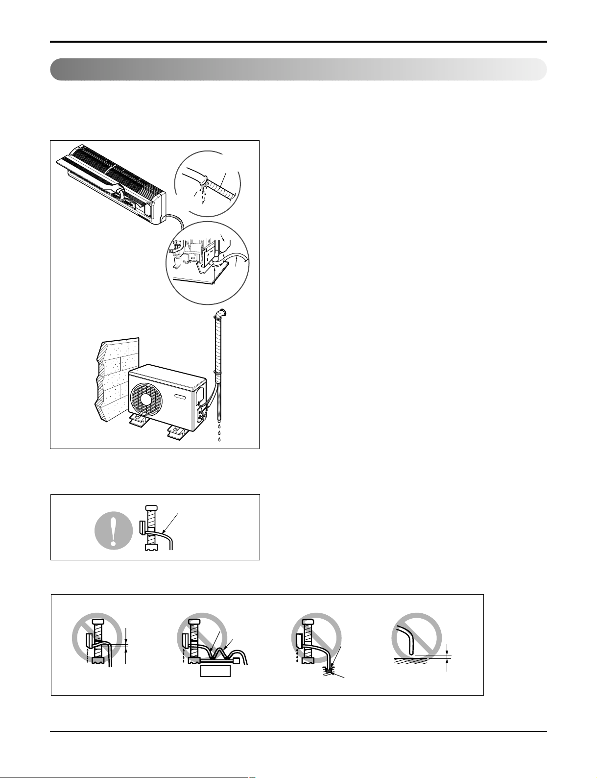
Checking The Drainage
• Pour a glass of water on the drain pan.
• Ensure the water flows through the drain hose of the indoor unit without any leakage and goes out the
drain exit.
Drain piping
• The drain hose should point downward for easy drain flow.
Drain pan
Drain
hose
Leakage
checking
Connecting area
drain hose
Leakage
checking
• Avoid these situations.
Do not raise
Accumulated
drain water
Tip of drain hose
dipped in water
Air
Waving
Water
leakage
Water
leakage
Ditch
Less than
50mm gap
Water
leakage
Installation
Downward slope
Page 29

Service Manual 29
Forming The Piping
Form the piping by wrapping the connecting portion of the indoor unit with insulation material and secure it with two kinds
of vinyl tapes.
• If you want to connect an additional drain hose,
the end of the drain outlet should be routed
above the ground. Secure the drain hose appropriately.
In cases where the outdoor unit is
installed below the indoor unit perform the
following.
• Tape the piping, drain hose and connecting
cable from down to up.
• Secure the tapped piping along the exterior wall
using saddle or equivalent.
Taping
Drain
hose
Pipings
Connecting
cable
Trap is required to prevent water
from entering into electrical parts.
Seal small openings
around pipings with a
gum type sealer.
In cases where the Outdoor unit is
installed above the Indoor unit perform
the following.
• Tape the piping and connecting cable from
down to up.
• Secure the taped piping along the exterior wall.
Form a trap to prevent water entering the room.
• Fix the piping onto the wall by saddle or equivalent.
Seal a small opening
around the pipings
with gum type sealer.
Trap
Trap
Installation
Page 30

30 Room Air Conditioner
Air Purging
Air purging With Vacuum Pump
Lo Hi
Indoor unit
Outdoor unit
Manifold valve
Charge hose
Nitrogen gas
cylinder(in vertical
standing position)
Pressure
gauge
Air and moisture remaining in the refrigerant system have undesirable effects as indicated below.
• Pressure in the system rises.
• Operating current rises.
• Cooling(or heating) efficiency drops.
• Moisture in the refrigerant circuit may freeze and block capillary tubing.
• Water may lead to corrosion of parts in the refrigeration system.
Therefore, the indoor unit and tubing between the indoor and outdoor unit must be leak tested and
evacuated to remove any noncondensables and moisture from the system.
Preparation
• Check that each tubing(both liquid and gas side
tubes) between the indoor and outdoor units have
been properly connected and all wiring for the test
run has been completed. Remove the service
valve caps from both the gas and the liquid side on
the outdoor unit. Note that both the liquid and the
gas side service valves on the outdoor unit are
kept closed at this stage.
Leak test
• Connect the manifold valve(with pressure gauges)
and dry nitrogen gas cylinder to this service port
with charge hoses.
• Pressurize the system to no more than 150
P.S.I.G. with dry nitrogen gas and close the cylinder valve when the gauge reading reached 150
P.S.I.G. Next, test for leaks with liquid soap.
• Do a leak test of all joints of the tubing(both
indoor and outdoor) and both gas and liquid side
service valves.
Bubbles indicate a leak. Be sure to wipe off the
soap with a clean cloth.
• After the system is found to be free of leaks,
relieve the nitrogen pressure by loosening the
charge hose connector at the nitrogen cylinder.
When the system pressure is reduced to normal,
disconnect the hose from the cylinder.
Be sure to use a manifold valve for air purging. If it
is not available, use a stop valve for this purpose.
The "Hi" knob of the manifold valve must always be
kept close.
To avoid nitrogen entering the refrigerant system in
a liquid state, the top of the cylinder must be higher
than its bottom when you pressurize the system.
Usually, the cylinder is used in a vertical standing
position.
Installation
Page 31

Service Manual 31
Evacuation
• Connect the charge hose end described in the
preceding steps to the vacuum pump to evacuate
the tubing and indoor unit.
Confirm the "Lo" knob of the manifold valve is
open. Then, run the vacuum pump.
The operation time for evacuation varies with tubing length and capacity of the pump. The following table shows the time required for evacuation.
• When the desired vacuum is reached, close the
"Lo" knob of the manifold valve and stop the vacuum pump.
Finishing the job
• With a service valve wrench, turn the valve stem
of liquid side valve counter-clockwise to fully
open the valve.
• Turn the valve stem of gas side valve counterclockwise to fully open the valve.
• Loosen the charge hose connected to the gas
side service port slightly to release the pressure,
then remove the hose.
• Replace the flare nut and its bonnet on the gas
side service port and fasten the flare nut securely
with an adjustable wrench. This process is very
important to prevent leakage from the system.
• Replace the valve caps at both gas and liquid
side service valves and fasten them tight.
This completes air purging with a vacuum pump.
The air conditioner is now ready to test run.
(1) Remove the caps from the gas side and liquid side
valves.
(2) Remove the service-port cap from the gas side
valve.
(3) To open the gas side valve turn the valve stem
counterclockwise approximately 90°, wait for about
2~3 seconds, and close it.
(4) Apply a soap water or a liquid neutral detergent on
the indoor unit connection or outdoor unit connections by a soft brush to check for leakage of the connecting points of the piping.
(5) If bubbles come out, the pipes have leakage.
Soap water method
Suction Line
Evaporator Line
Cap
Hexagonal wrench
3-way valve
(Open)
3-way valve
(Close)
Required time for evacuation when 4 CMF vacu-
um pump is used
10 min. or more 15 min. or more
If tubing length is less
than 10m (33 ft)
if tubing length is longer
than 10m (33 ft)
Indoor unit
Outdoor unit
Lo Hi
Manifold valve
Vacuum pump
Pressure
gauge
Open
Close
Installation
Page 32

32 Room Air Conditioner
Charging
■ Each outdoor unit is factory charged (nameplate charge) for the evaporator as well as a 7.5m(25ft)
line set. Any time a line set is used either shorter or longer then the nominal 7.5m(25ft) line set
length the refrigerant charge has to be adjusted.
■ Whether the line set is made shorter or longer you must adjust the charge based on how many ft of
tubing are either added or removed based on 20g(0.22oz) of R-410A per meter(foot).
Example: A 30ft line set is used
5 additional ft X 0.22 ounce per foot= add 1.1 ounces of R-410A
Important:(Unit is critically charged)
If you are ever uncertain of the unit charge, reclaim, evacuate and weigh in the correct charge using the unit nameplate charge
adjusting for line sets longer or shorter than 7.5m(25ft).
Confirm the refrigerant R-410A. Use manifold gauge and hose for R-410A.
Pipe Size
Capacity
(Btu/h)
Suction
Evap
Max.
length
A m(ft)
Max.
Elevation
B m(ft)
Standard
Length
m(ft)
9k
3/8" 1/4" 7.5(25) 7.5(25) 15(49) 20(0.22)
1/2" 1/4" 7.5(25) 7.5(25) 15(49) 20(0.22)
12k 1/2" 1/4" 7.5(25) 7.5(25) 15(49) 20(0.22)
18k
1/2" 1/4" 7.5(25) 15(49) 30(98) 20(0.22)
5/8" 1/4" 7.5(25) 7.5(25) 15(49) 20(0.22)
24k 5/8" 1/4" 7.5(25) 7.5(25) 15(49) 20(0.22)
Installation
Page 33

Service Manual 33
Outside ambient TEMP. The pressure of the gas side service valve
95°F(35°C)
8.5~9.5kg/cm2 G(120~135 P.S.I.G.)
Settlement of outdoor unit
■ Anchor the outdoor unit with a bolt and
nut(ø10mm(0.39in) tightly and horizontally on a
concrete or rigid mount.
■ When installing on the wall, roof or rooftop,
anchor the mounting base securely with a nail
or wire assuming the influence of wind and
earthquake.
■ In the case when the vibration of the unit is conveyed to the hose, secure the unit with an anti-
vibration rubber.
1. Check that all tubing and wiring have been
properly connected.
2. Check that the gas and liquid side service
valves are fully open.
Prepare remote control
1. Remove the battery cover
by pulling it according to the
arrow direction.
2. Insert new batteries making
sure that the (+) and (–) of
battery are installed correctly.
3. Reattach the cover by
pushing it back into position.
NOTE:
• Use 2 AAA(1.5volt) batteries. Do not use
rechargeable batteries.
• Remove the batteries from the remote control if
the system is not going to be used for a long
time.
Evaluation of the performance
Operate unit for 15~20 minutes, then check the
system refrigerant charge:
1. Measure the pressure of the gas side service valve.
NOTE: If the actual pressure are higher than
shown, the system is most likely overcharged, and charge should be removed. If
the actual pressure are lower than shown,
the system is most likely undercharged,
and charge should be added.
The air conditioner is now ready for use.
Bolt
Tubing connection
This is performed when the unit is to be relocated
or the refrigerant circuit is serviced.
Pump Down means collecting all refrigerant in the outdoor unit without loss of refrigerant.
CAUTION:
Be sure to perform Pump Down procedure with the unit
cooling mode.
Pump Down Procedure
1. Connect a low-pressure gauge manifold hose to the
charge port on the gas side service valve.
2. Open the gas side service valve halfway and purge the
air from the manifold hose using the refrigerant gas.
3. Close the liquid side service valve(all the way in).
4. Turn on the unit's operating switch and start the cooling
operation.
5. When the low-pressure gauge reading becomes 1 to
0.5kg/cm2G(14.2 to 7.1 P.S.I.G.), fully close the gas
side valve stem and then quickly turn off the unit. At that
time, Pump Down has been completed and all refrigerant will have been collected in the outdoor unit.
PUMP DOWN
2. Measure the temperature of the intake and discharge
of air.
3. Ensure the difference between the intake tem-
perature and the discharge is more than
14.4°F(8°C) (Cooling) or (Heating).
4. For reference; the gas side pressure of optimum
condition is as below.(Cooling)
Discharge
temperature
Discharge air
Intake temperature
Test Running
Test Running
Page 34

Operation
Function of Controls
Operation
• DISPLAY
1) C/O Model
Operation Indicator
• ON while in appliance operation, OFF while in appliance pause.
• Flashing while in disconnection or short in Thermistor. (3 sec off / 0.5 sec on)
Timer Indicator
• ON while in timer mode (on/off), OFF when timer mode is completed or canceled.
Comp. Running Incidator
• While in appliance operation, ON while in outdoor unit compressor running, OFF while in compressor off.
2) H/P Model
Operation Indicator
• ON while in appliance operation, OFF while in appliance pause.
• Flashing while in disconnection or short in Thermistor. (3 sec off / 0.5 sec on)
Timer Indicator
• ON while in timer mode (on/off), OFF when timer mode is completed or canceled.
Defrost Indicator
• OFF except when hot start during heating mode operation or while in defrost control.
■ Cooling Mode Operation
• When the intake air temperature reaches 0.5°C(0.9°F) below the setting temp, the compressor and
the outdoor fan stop.
• When it reaches 0.5°C(0.9°F) above the setting temp, they start to operate again.
Compressor ON Temp ➲ Setting Temp+0.5°C(0.9°F)
Compressor OFF Temp ➲ Setting Temp-0.5°C(0.9°F)
• While in compressor running, operating with the airflow speed set by the remote control. While in
compressor not running, operating with the low airflow speed regardless of the setting.
■ Healthy Dehumidification Mode
• When the dehumidification operation input by the remote control is received, the intake air temperature is detected and the setting temp is automatically set according to the intake air temperature.
26°C(78.8°F) ≤ Intake Air Temp ➲ 25°C(77°F)
24°C(75.2°F) ≤ Intake Air Temp<26°C(78.8°F) ➲ Intake Air Temp-1°C(1.8°F)
18°C(64.4°F) ≤ Intake Air Temp<24°C(75.2°F) ➲ Intake Air Temp-0.5°C(0.9°F)
Intake Air Temp<18°C(64.4°F) ➲ 18°C(64.4°F)
34 Room Air Conditioner
Page 35

Service Manual 35
Operation
• While in compressor off, the indoor fan repeats low airflow speed and pause.
• While the intake air temp is between compressor on temp. and compressor off temp., 10-min dehumidification operation and 4-min compressor off repeat.
Compressor ON Temp. ➲ Setting Temp+0.5°C(0.9°F)
Compressor OFF Temp. ➲ Setting Temp-0.5°C(0.9°F)
• In 10-min dehumidification operation, the indoor fan operates with the low airflow speed.
■ Heating Mode Operation
• When the intake air temp reaches +3°C(5.4°F) above the setting temp, the compressor is turned
off. When reaches the setting temp, the compressor is turned on.
Compressor ON Temp. ➲ Setting Temp.
Compressor OFF Temp. ➲ Setting Temp.+3°C(5.4°F)
• While in compressor on, the indoor fan is off when the indoor pipe temp. is below 20°C(68°F), when
above 28°C(82.4°F) , it operates with the low or setting airflow speed. When the indoor pipe temp is
between 20°C and 28°C(82.4°F), it operates with Super-Low(while in sleep mode, with the medium
airflow speed).
• While in compressor off, the indoor fan is off when the indoor pipe temp is below 33°C(91.4°F),
when above 35°C(95°F) , it operates with the low airflow speed.
• If overloaded while in heating mode operation, in order to prevent the compressor from OLP operation, the outdoor fan is turned on/off according to the indoor pipe temp.
• While in defrost control, both of the indoor and outdoor fans are turned off.
■ Defrost Control
• While in heating mode operation in order to protect the evaporator pipe of the outdoor unit from
freezing, reversed to cooling cycle to defrost the evaporator pipe of the outdoor unit.
• After 40 min heating mode operation, at 4 min interval, whether to carry out defrost control or not
and the time of defrost control are determined according to the following conditions.
1) While in heating mode operation, the maximum of the indoor pipe temperature is measured and it is
compared with the present indoor pipe temperature to get the difference of the indoor pipe temperatures (=the maximum temperature of indoor pipe & the present temperature of indoor pipe),
according to which, whether to carry out defrost control or not is determined.
2) According to the need of defrost control shown above and the elapsed time of heating mode opera-
tion at that moment, the defrost control time is determined.
3) When the determined time of defrost control is below 7 min, heating mode operation continues
without carrying out defrost control. According to the procedure stated above, the determination is
made again. When the defrost control time is 7 min or longer, defrost control is then carried out.
• While in defrost control, the minimum temp of the indoor pipe is measured and it is compared with
the present temp of the indoor pipe to get the difference of the indoor pipe temperatures (=the present temperature of the indoor pipe & the minimum temperature of the indoor pipe). When the difference is 5°C(41°F) or higher, defrost control is completed and heating mode operation is carried out.
• While in defrost control, if the defrost time determined before the start of defrost control is completed, defrost control stops and heating mode operation is carried out regardless of the above condition.
• When the indoor pipe temp is 42°C(107.6°F) or above, defrost control is not carried out even if the
condition is one of the defrost conditions above.
• While in defrost control, the compressor is on and the indoor fan, the outdoor fan, and the 4 way
valve are off.
Page 36

36 Room Air Conditioner
■ Airflow Speed Selection
• The airflow speed of the indoor fan is set to high, medium, low, or chaos (auto) by the input of the
airflow speed selection key on the remote control.
■ Sleep Timer Operation
• When the sleep time is reached after <1,2,3,4,5,6,7,0(cancel) hr> is input by the remote control
while in appliance operation, the operation of the appliance stops.
• While the appliance is on pause, the sleep timer mode cannot be input.
• While in cooling mode operation, 30 min later since the start of the sleep timer, the setting tempera-
ture increases by 1°C(1.8°F). After another 30 min elapse, it increases by 1°C(1.8°F) again.
• When the sleep timer mode is input while in cooling cycle mode, the airflow speed of the indoor fan
is set to the low.
• When the sleep timer mode is input while in heating cycle mode, the airflow speed of the indoor fan
is set to the medium.
■ Chaos Natural Wind Mode
• When the Chaos Natural Wind mode is selected and then operated, the high, medium, or low speed
of the airflow mode is operated for 2~15 sec. randomly by the Chaos Simulation.
■ Jet Cool Mode Operation (C/O Model)
• If the Jet Cool key is input at any operation mode while in appliance operation, the Jet Cool mode
operates.
• In the Jet Cool mode, the indoor fan is operated at super-high speed for 30 min at cooling mode
operation.
• In the Jet Cool mode operation, the room temperature is controlled to the setting temperature,
18°C(64.4°F)
• When the sleep timer mode is input while in the Jet Cool mode operation, the Jet Cool mode has
the priority.
• When the Jet Cool key is input, the upper/lower vanes are reset to those of the initial cooling mode
and then operated in order that the air outflow could reach further.
■ Jet Cool Mode Operation (H/P Model)
• While in heating mode or Fuzzy operation, the Jet Cool key cannot be input. When it is input while
in the other mode operation (cooling, dehumidification, ventilation), the Jet Cool mode is operated.
•
In the Jet Cool mode, the indoor fan is operated at super-high speed for 30 min at cooling mode operation.
• In the Jet Cool mode operation, the room temperature is controlled to the setting temperature,
18°C(64.4°F).
• When the sleep timer mode is input while in the Jet Cool mode operation, the Jet Cool mode has
the priority.
• When the Jet Cool key is input, the upper/lower vanes are reset to those of the initial cooling mode
and then operated in order that the air outflow could reach further.
Operation
Page 37

Service Manual 37
Operation
■ Forced operation
• Operation procedures when the remote control can't be used.
• The operation will be started if the power button is pressed.
• If you want to stop operation, re-press the button.
• While in forced operation, the key input by the remote control has no effect and the buzzer sounds
10 times to indicate the forced operation.
■ Test operation
•
During the TEST OPERATION, the unit operates in cooling mode at high speed fan, regardless of
room temperature and resets in 18±1 minutes.
•
During test operation, if remote controller signal is received, the unit operates as remote controller
sets.
If you want to use this operation, open the front panel upward and Press the power button let it be
pressed for about 3 seconds.
•
If you want to stop the operation, re-press the button.
■ Auto restart
•
In case the power comes on again after a power failure, Auto Restarting Operation is the function to
operate procedures automatically to the previous operating conditions.
■ Protection of the evaporator pipe from frosting
• If the indoor pipe temp is below 0°C in 7 min. after the compressor operates without any pause
while in cooling cycle operation mode, the compressor and the outdoor fan are turned off in order to
protect the indoor evaporator pipe from frosting.
• When the indoor pipe temp is 7°C or higher after 3 min. pause of the compressor, the compressor
and the outdoor fan is turned on according to the condition of the room temperature.
■ Buzzer Sounding operation
• When the appliance-operation key is input by the remote control, the short "beep-beep-" sounds.
• When the appliance-pause key is input by the remote control, the long "beep—" sounds.
Heat pump Model
Cooling Model
Room Temp. ≥ 24°C(75.2°F) 21°C(69.8°F) ≤Room Temp. < 24°C(75.2°F) Room Temp. < 21°C(69.8°F)
Operating mode Cooling Cooling Healthy Dehumidification Heating
Indoor FAN Speed High High High High
Setting Temperature 22°C(71.6°F) 22°C(71.6°F) 23°C(73.4°F) 24°C(75.2°F)
Page 38

38 Room Air Conditioner
Self-diagnosis Function
Display Function
1. Heating Model 2. Cooling Model
• Cooling, Soft Dry, Fan, Heating • Cooling, Soft Dry, Fan
• Hot-start, Deice
Operation Indicator
Deicer Indicator
Operation Indicator
Compressor on Indicator
Error
Code
1
Error Display LED
(Indoor body operation LED)
Error contents
• Indoor room temperature
thermistor open/short
• Indoor pipe temperature
thermistor open/short.
• Indoor Thermistor
assembly check
SVC check point
Operation
(once)
3sec 3sec 3sec
Page 39

Service Manual 39
Operation
Remote Control Operations
The controls will look like the following.
1. START/STOP BUTTON
Operation starts when this button is pressed and
stops when the button is pressed again.
2. OPERATION MODE SELECTION BUTTON
Used to select the operation mode.
3. ROOM TEMPERATURE SETTING BUTTONS
Used to select the room temperature.
4. INDOOR FAN SPEED SELECTOR
Used to select fan speed in four steps
low, medium, high and CHAOS.
5.
JET COOL
Used to start or stop the speed cooling.(speed cooling
operates super high fan speed in cooling mode.)
6. CHAOS SWING BUTTON
Used to stop or start louver movement and set
the desired up/down airflow direction.
7. ON/OFF TIMER BUTTONS
Used to set the time of starting and stopping operation.
(See page 22)
8. TIME SETTING BUTTONS
Used to adjust the time. (See page 22)
9. TIMER SET/CANCEL BUTTON
Used to set the timer when the desired time is obtained and
to cancel the Timer operation. (See page 22)
10. SLEEP MODE AUTO BUTTON
Used to set Sleep Mode Auto operation.
(See page 22)
11. AIR CIRCULATION BUTTON
Used to circulate the room air without cooling or heating.
(See page 23)
12. ROOM TEMPERATURE CHECKING BUTTON
Used to check the room temperature.
13. NEO PLASMA(OPTIONAL)
Used to start or stop the plasma-purification function. (See
page 20)
14. HORIZONTAL AIRFLOW DIRECTION CONTROL
BUTTON (OPTIONAL)
Used to set the desired horizontal airflow direction.
15. RESET BUTTON
Used prior to resetting time.
16. 2nd F Button
Used prior to using modes printed in blue at the bottom of
buttons. (See page 21)
17. AUTO CLEAN (OPTIONAL)
Used to set Auto Clean mode.
18. ˚C TO ˚F SWITCHING BUTTON
Used to switch temperature reading from Centigrade to
Fahrenheit.
ON
OFF
CANCEL
AUTO CLEAN
SET
1
3
5
4
9
10
12
14
16
18
7
2
8
13
15
11
6
Cooling Operation
Auto Operation or Auto Changeover
Healthy Dehumidification Operation
Flip-up door
(opened)
Heating Operation
Signal transmitter
•
Cooling Model( ), Heat Pump Model( )
17
Operation Mode
Page 40

40 Room Air Conditioner
Disassembly
Indoor Unit
Disconnect the unit from power supply before making any checks.
Be sure the power switch is set to “OFF”.
To remove the Grille from the Chassis.
• Set the up-and-down air discharge louver to open
position (horizontally) by finger pressure.
• Remove the securing screws.
• To remove the Grille, pull the lower left and right
side of the grille toward you (slightly tilted) and lift it
straight upward.
1. Before removing the control box, be sure to
take out the wire screwed at the other end.
Earth
Conductor
Operation
Page 41

Service Manual 41
Disassembly
2. To remove the Control Box.
• Remove securing screws.
• Pull the control box out from the chassis
carefully.
3. To remove the Discharge Grille.
• Unhook the discharge grille and pull the
discharge grille out from the chassis carefully.
4. To remove the Evaporator.
• Remove 3 screws securing the evaporator(at the
left 2EA in the Eva Holder, at the right 1EA).
Screw
• When repair, do not damage the Caution label.
Page 42

42 Room Air Conditioner
• Unhook the tab on the right inside of the chassis
at the same time, slightly pull the evaporator
toward you until the tab is clear of the slot.
5.To remove the Motor Cover
• Remove 2 securing screw.
• Pull the motor cover out from the chassis
carefully.
6.To remove the Cross-Flow Fan
• Loosen the screw securing the cross-flow fan to
the fan motor (do not remove).
• Lift up the right side of the cross-flow fan and the
fan motor, separate the fan motor from the
cross-flow fan.
• Remove the left end of the cross-flow fan from
the self-aligning bearing.
Motor cover
Bearing
Cross-flow fan
Disassembly
Page 43

Service Manual 43
Troubleshooting Guide
Troubleshooting Guide
INDOOR UNIT OUTDOOR UNIT
INDOOR UNIT OUTDOOR UNIT
HEAT
EXCHANGE
(EVAPORATOR)
HEAT
EXCHANGE
(EVAPORATOR)
HEAT
EXCHANGE
(CONDENSER)
HEAT
EXCHANGE
(CONDENSER)
COMPRESSOR
COMPRESSOR
ACCUMU
LATOR
GAS SIDE
GAS SIDE
3-WAY VALVE
LIQUID SIDE
LIQUID SIDE
3-WAY VALVE
CAPILLARY TUBE
CAPILLARY TUBE
CHECK VALVE
(Heating Model only)
COOLING
HEATING
REVERSING
VALVE
(Heating Model Only)
(1) Cooling Only Models
Refrigeration Cycle Diagram
(2) Cooling & Heating Models
Page 44

44 Room Air Conditioner
Troubleshooting Guide
2-way, 3-way Valve
2-way Valve (Liquid Side) 3-way Valve (Gas Side)
Shaft position Shaft position Service port
Closed Closed Closed
(with valve cap) (with valve cap) (with cap)
Open Closed Open
(counter-clockwise) (clockwise) (push-pin or with
vacumm pump)
Open Open Closed
(with valve cap) (with valve cap) (with cap)
Closed Open Open
(clockwise) (counter-clockwise) (connected manifold
gauge)
Open Open Open
(with charging
cylinder)
Open Open Open
(with charging
cylinder)
Open Open
Open Open
Works
Shipping
Air purging
(Installation)
Operation
Pumping down
(Transfering)
Evacuation
(Servicing)
Gas charging
(Servicing)
Pressure check
(Servicing)
Gas releasing
(Servicing)
1.
2.
3.
4.
5.
6.
Valve cap
Open position
Closed position
Pin
Service
port
Service
port cap
To outdoor unit
Flare nut
To
piping
connection
To outdoor unit
Hexagonal wrench (4mm)
Open position
Closed position
To
piping
connection
Flare nut
Open
(with charging
cylinder)
Open
(with charging
cylinder)
Page 45

Service Manual 45
Troubleshooting Guide
• Procedure
(1) Confirm that both the 2-way and 3-way
valves are set to the open position.
– Remove the valve stem caps and confirm
that the valve stems are in the raised position.
– Be sure to use a hexagonal wrench to
operate the valve stems.
(2) Operate the unit for 10 to 15 minutes.
(3) Stop operation and wait for 3 minutes,
then connect the charge set to the service
port of the 3-way valve.
– Connect the charge hose with the push pin
to the service port.
(4) Air purging of the charge hose.
– Open the low-pressure valve on the charge
set slightly to air purge from the charge
hose.
(5) Set the 2-way valve to the closed position.
(6) Operate the air conditioner at the cooling
cycle and stop it when the gauge indicates 1kg/cm
2
g.
(7) Immediately set the 3-way valve to the
closed position.
– Do this quickly so that the gauge ends up
indicating 3 to 5kg/cm
2
g.
(8) Disconnect the charge set, and mount the
2-way and 3-way valve’s stem nuts and
the service port nut.
– Use torque wrench to tighten the service
port nut to a torque of 1.8 kg.m.
– Be sure to check for gas leakage.
Lo
Closed
Purge the air
Outdoor unit
Indoor unit
Liquid side
Gas side
CLOSE
Open
2-Way
valve
3-Way
valve
CLOSE
Pumping Down
Do not use the existing charge set for R-22.
It is necessary to use new charge set for R410A. The pressure of R-410A is 1.6 times
higher than that of R-22. Thus, the high pressure side gauge of charge set should be used
higher pressure gauge of 50kg/cm2range.
Page 46

46 Room Air Conditioner
Troubleshooting Guide
Balance Refrigerant of the 3-way Valve
(Gas leakage)
• Procedure
(1) Confirm that both the 2-way and 3-way
valves are set to the back seat.
(2) Connect the charge set to the 3-way
valve’s port.
– Leave the valve on the charge set closed.
– Connect the charge hose to the service
port.
(3) Open the valve (Lo side) on the charge set
and discharge the refrigerant until the
gauge indicates 0 kg/cm
2
G.
– If there is no air in the refrigerant cycle (the
pressure when the air conditioner is not
running is higher than 1 kg/cm
2
G), discharge the refrigerant until the gauge indicates 7.1PSI. if this is the case, it will not
be necessary to apply a evacuatin.
– Discharge the refrigerant gradually; if it is
discharged too suddenly, the refrigeration
oil will also be discharged.
Lo
Open
Open
3-Way
valve
3-Way
valve
Gas side
CLOSEOPEN
Outdoor unit
Liquid side
Indoor unit
Page 47

Service Manual 47
Troubleshooting Guide
Evacuation
(All amount of refrigerant leaked)
• Procedure
(1) Connect the vacuum pump to the center
hose of charge set center hose
(2) Evacuation for approximately one hour.
– Confirm that the gauge needle has moved
toward -76 cmHg (vacuum of 4 mmHg or
less).
(3) Close the valve (Lo side) on the charge
set, turn off the vacuum pump, and confirm that the gauge needle does not move
(approxima-tely 5 minutes after turning off
the vacuum pump).
(4) Disconnect the charge hose from the vac-
uum pump.
– Vacuum pump oil.
If the vacuum pump oil becomes dirty or
depleted, replenish as needed.
Lo
Open
Open
Vacuum pump
3-Way
valve
Outdoor unit
Liquid side
Indoor unit
Gas side
3-Way
valve
CLOSE
OPEN
Use vacuum pump equipped with check value
applied to be prevented from flowing backward.
Page 48

48 Room Air Conditioner
Troubleshooting Guide
Gas Charging
(After Evacuation)
• Procedure
(1) Connect the charge hose to the charging
cylinder.
– Connect the charge hose which you dis-
connected from the vacuum pump to the
valve at the bottom of the cylinder.
– If you are using a gas cylinder, also use a
scale and reverse the cylinder so that the
system can be charged with liquid.
(2) Purge the air from the charge hose.
– Open the valve at the bottom of the cylin-
der and press the check valve on the
charge set to purge the air. (Be careful of
the liquid refrigerant). The procedure is
the same if using a gas cylinder.
(3) Open the valve (Lo side on the charge set
and charge the system with liquid refrigerant.
– If the system can not be charged with the
specified amount of refrigerant, it can be
charged with a little at a time (approximately 0.33 lb each time) while operating the air
conditioner in the cooling cycle; however,
one time is not sufficient, wait approximately 1 minute and then repeat the procedure (pumping down-pin).
(4) Immediately disconnect the charge hose
from the 3-way valve’s service port.
– Stopping partway will allow the gas to be
discharged.
– If the system has been charged with liquid
refrigerant while operating the air conditioner turn off the air conditioner before
disconnecting the hose.
(5) Mount the valve stem nuts and the service
port nut.
– Use torque wrench to tighten the service
port nut to a torque of 13 lb·ft.
– Be sure to check for gas leakage.
This unit is charged with R-410A.
Pay attention not to charge R-22.
\
This is different from previous procedures.
Because you are charging with liquid refrigerant
from the gas side, absolutely do not attempt to
charge with larger amounts of liquid refrigerant
while operating the air conditioner.
Liquid side
Gas side
Lo
Charging
cylinder
Indoor unit
Check valve
(1)
OPEN
CLOSE
3-Way
Open
valve
Open
3-Way
valve
Outdoor unit
Page 49

Service Manual 49
Troubleshooting Guide
Additional gas charging
(Gas leakage)
• When refrigerant is insufficient by leakage, recharge the unit with the refrigerant up to normal operating suction pressure.
• Use the graph or the equation below to get operating suction pressure according to indoor and outdoor temperature.
Suction pressure was measured at 3-way valve service port after operating the unit for 10 minutes.
The method of using graph
- Find outdoor temperature.
- Find indoor temperature onto the curve of outdoor temperature.
- Read suction pressure at the axis of ordinates.
The method of using equation
-. Calculate suction pressure after putting indoor and outdoor temperature into the equation.
184.9
(At operating the Unit for 10 minutes)
Suction Pressure
(PSI)
Outdoor Temp.
(˚F)
Indoor Temp. (˚F)
170.7
156.5
142.2
128
113.8
99.5
85
71.1
41 50 59 68 77 86 95 104
122˚F
104˚F
86˚F
68˚F
50˚F
0˚F
Operating Suction Pressure (For R410A)
(According to Indoor & Outdoor Temperature)
Page 50

50 Room Air Conditioner
Troubleshooting Guide
Trouble analysis
1. Check temperature difference between intake and discharge air and operating current.
Temp. Difference
Temp. difference : approx. 0°F(0°C)
Current : less than 80% of
rated current
Temp. difference : approx. 14°F(8°C)
Current : less than 80% of
rated current
Temp. difference :
less than 14°F(8°C)
Current : over the reated
current
Temp. difference : over 14°F(8°C)
Operating Current
• All amount of refrigerant leaked
out. Check refrigeration cycle.
• Refrigerant leakege
Clog of refrigeration cycle
Defective compressor
• Excessive amount of refrigerant
• Normal
Temperature difference between intake and discharge air depends on room air humidity. When the room air
humidity is relativery higher, temperature difference is smaller. When the room air humidity is relatively lower
temperature difference is larger.
2. Check temperature and pressure of refrigeration cycle.
1. The suction pressure is usually 120.9~135.1PSI(Cooling) at normal condition.
2. The temperature can be measured by attaching the thermometer to the low pressure tubing and wrap it with
putty.
NOTICE
NOTICE
Suction pressure Temperature
(Compared with (Compared with Cause of Trouble Description
the normal value) the normal valve)
Defective compressor Current is low.
Defective 4-way reverse valve
Excessive amount of High pressure does not quickly
Normal refrigerant rise at the beginning of
operation.
Insufficient amount of Current is low.
Lower Higher refrigerant (Leakage)
Clogging Current is low.
High
Higher
Cycle Parts
Page 51

Service Manual 51
Troubleshooting Guide
Electronic Parts (9k model)
Product does not operate at all.
(* Refer to Electronic Control Device drawing and Schematic diagram.)
Turn off Main Power
Turn on Main Power
Does "beeping" sound is made from the Indoor Unit?
Primarily, the operating condition of Micom is OK.
Check the voltage of power(About AC 115V, 60Hz)
• Main power's voltage
• Voltage applied to the unit
• Connecting method of Indoor/Outdoor connecting
cable
• Check PWB Ass'y(Outdoor unit)
- Fuse
- Pattern damage
- Varistor(ZNR01J)
Check the connection housing for contacting
• Connector related to CN-POWER
• Connector related to CN-FAN
• Connector contacting of Outdoor Fan/Compressor
• Display PWB Ass'y Check
• Connector related to CN-DC/DC
Check each load(Indoor/Outdoor Fan Motor,
Compressor, Stepping Motor) and contacting
condition of related connector(including connecting
cable of Indoor/Outdoor Unit)
PCB Board Operation Check
Items
• Power Transformer
(Outdoor unit)
- Input Voltage
- Output Voltage
• IC01D(7812) Output
(Indoor/Outdoor unit)
• IC02D(7805) Output
(Indoor unit)
IC03D(7805) Output
(Outdoor unit)
• IC01A(KIA7036, Reset IC)
OSC01B(4MHz)
(Indoor/Outdoor unit)
• Replace SMPS
Module
• Replace IC01D
• Replace
IC02D(Indoor unit)
IC03D(Outdoor unit)
• Replace faulty parts
- About AC115V±10% - Check the power voltage
- About DC15V±3
• DC +12V
• DC +5V
• Voltage of Outdoor unit Micom No. 18,
Voltage of Indoor unit Micom No. 43 and
soldering condition
Content Remedy
NO
YES
(After 20 seconds)
Page 52

52 Room Air Conditioner
Troubleshooting Guide
Electronic Parts (18k model)
Product does not operate at all.
(* Refer to Electronic Control Device drawing and Schematic diagram.)
Turn off Main Power
Turn on Main Power
Does "beeping" sound is made from the Indoor Unit?
Primarily, the operating condition of Micom is OK.
Check the voltage of power(About AC 208V/AC 230V, 60Hz)
• Main power's voltage
• Voltage applied to the unit
• Connecting method of Indoor/Outdoor connecting
cable
• Check PWB Ass'y(Outdoor unit)
- Fuse
- Pattern damage
- Varistor(ZNR01J)
Check the connection housing for contacting
• Connector related to CN-POWER
• Connector related to CN-FAN
• Connector contacting of Outdoor Fan/Compressor
• Display PWB Ass'y Check
• Connector related to CN-DC/DC
Check each load(Indoor/Outdoor Fan Motor,
Compressor, Stepping Motor) and contacting
condition of related connector(including connecting
cable of Indoor/Outdoor Unit)
PCB Board Operation Check
Items
• Power Transformer
(Outdoor unit)
- Input Voltage
- Output Voltage
• IC01D(7812) Output
(Indoor/Outdoor unit)
• IC02D(7805) Output
(Indoor unit)
IC04D(7805) Output
(Outdoor unit)
• IC01A(KIA7036, Reset IC)
OSC01B(4MHz)
(Indoor/Outdoor unit)
• Replace SMPS
Module
• Replace IC01D
• Replace
IC02D(Indoor unit)
IC04D(Outdoor unit)
• Replace faulty parts
- About
AC 208V/AC 230V±10%
- Check the power voltage
- About DC15V±3
• DC +12V
• DC +5V
• Voltage of Outdoor unit Micom No. 18,
Voltage of Indoor unit Micom No. 43 and
soldering condition
Content Remedy
NO
YES
(After 20 seconds)
Page 53

Service Manual 53
Troubleshooting Guide
The product is not operate with the remote controller.
Turn on Main Power
While the compressor has been stopped, the compressor does not
operate owing to the delaying function for 3 minutes after stopped.
Caused by other parts except the remote controller
Cause by the remote controller
When the mark( ) is displayed in LCD screen, replace
battery.
Check the contact of CN-DISP connector.
When the compressor stopped Indoor Fan is driven by a low speed.
At this point the wind speed is not controlled by the remote controller.
(When operated in the Sleeping Mode, the wind speed is set to the
low speed by force.)
Check DISP PWB Ass'y
- Voltage between CN DISP - : DC +5V
When the detect switch(double key) inside the remote
controller door is fault, it is impossible to operate
temperature regulating( / ) and wind speed selecting.
Check the connecting circuit between the remote controller
MICOM (No. ) - R17(2Ω) - IR LED - Q1 - R16(2.2K Ω).
Check point
• Check the connecting circuit between PIN 43 R11L(1K) - C11L(680PF) - MICOM PIN
• Check Receiver Ass'y
Page 54

54 Room Air Conditioner
Troubleshooting Guide
Compressor/Outdoor Fan are unable to drive.(9k Model)
Turn on Main Power
Operate "Cooling Mode( )" by setting the desired temperature of the
remote controller is less than one of the indoor temperature by 2°F at least.
When in Fan Mode, Compressor/Outdoor Fan is stopped.
Check the sensor for indoor temperature is attached as close as to be
effected by the temperature of Heat Exchanger(EVA).
When the sensor circuit for indoor temperature and connector are in bad
connection or are not engaged, Compressor/Outdoor Fan is stopped.
• Check the related circuit of R02H(12.1K), R04H(6.2K), Micom (No.27)
(Indoor unit).
• Check the indoor temperature sensor is disconnected or not(About 10kΩ/ at 77°F).
When the temperature around Outdoor PWB Ass'y is above 163°F the
compressor is stop and only Outdoor Fan is operating.
Turn off Main Power
• Check the electrical wiring diagram of outdoor side.
• Check the abnormal condition for the component of Compressor/Outdoor
Fan Motor.
Check Relay(RY - COMP) for driving compressor.
• When the power(About AC110V) is applied to the connecting wire terminal support transferred to compressor, PWB Ass'y is normal.
• Check the circuit related to the relay(Outdoor unit).
Check point COMP ON COMP OFF
Between Micom(No.
DC5V DC0V
5) and GND
Between IC01M, IC02M(No. 9)
Below DC 1V
About DC12V
and
IC01M, IC02M(No. 8)
(app)
Page 55

Service Manual 55
Troubleshooting Guide
Compressor/Outdoor Fan are unable to drive.(18k Model)
Turn on Main Power
Operate "Cooling Mode( )" by setting the desired temperature of the
remote controller is less than one of the indoor temperature by 2°F at least.
When in Fan Mode, Compressor/Outdoor Fan is stopped.
Check the sensor for indoor temperature is attached as close as to be
effected by the temperature of Heat Exchanger(EVA).
When the sensor circuit for indoor temperature and connector are in bad
connection or are not engaged, Compressor/Outdoor Fan is stopped.
• Check the related circuit of R02H(12.1K), R04H(6.2K), Micom (No.27)
(Indoor unit).
• Check the indoor temperature sensor is disconnected or not(About 10kΩ/ at 77°F).
When the temperature around Outdoor PWB Ass'y is above 163°F the
compressor is stop and only Outdoor Fan is operating.
Turn off Main Power
• Check the electrical wiring diagram of outdoor side.
• Check the abnormal condition for the component of Compressor/Outdoor
Fan Motor.
Check Relay(RY - COMP) for driving compressor.
• When the power(About AC200V) is applied to the connecting wire termi-
nal support transferred to compressor, PWB Ass'y is normal.
• Check the circuit related to the relay(Outdoor unit).
Check point COMP ON COMP OFF
Between Micom(No.
DC5V DC0V
5, 6) and GND
Between IC01M, IC02M(No. 9)
Below DC 1V
About DC12V
and
IC01M, IC02M(No. 8)
(app)
Page 56

56 Room Air Conditioner
Troubleshooting Guide
When indoor Fan does not operate.
Check connecting condition of the CN-MOTOR CONNECTOR
Does the voltage of terminal of CN-DC/DC CONNECTOR in
Indoor unit corresponds to the values in the table of page 56
Do the voltage of terminal of
CN-DC/DC CONNECTOR in
Outdoor unit corresponds to the
values in the table of page 56
Check the patterns and the
conditions of outdoor unit
PWB Assy's.
Check the connecting condition and disconnection of
connecting wires between
Indoor and Outdoor unit.
Check the pattern and the
condition of Indoor unit PWB
Ass'y.
Check the interference of Indoor Fan.
Does the voltage of each terminals of CN-MOTOR CONNECTOR in
Indoor unit corresponds to values in the Table of page 56
Check the motor of Indoor Fan
Indoor Fan may be stopped in the Soft Dry Mode(change to the Cooling Operation Mode).
Indoor Fan is to be stopped when Indoor pipe(coil) termperature is lower than 79°F.
(At that times, Defrost indicator is turned on)
NO
YES
Page 57

Service Manual 57
Troubleshooting Guide
When Vertical Louver does not operate.
• Confirm that the Vertical Louver is normally geared with the shaft of
Stepping Motor.
• If the regular torque is detected when rotating the Vertical Louver with
hands Normal
• Check the connecting condition of CN-UP/DOWN Connector
• Check the soldering condition(on PWB) of CN-UP/DOWN Connector
Check the operating circuit of the Vertical Louver
• Confirm that there is DC +12V between pin
(RED) of CN-UP/DOWN and
GND.
• Confirm that there is a soldering short at following terminals.
- Between 60 , 61
, 62 and 63
of MICOM
- Between
2 , 3 , 4 and 5 of IC01M
- Between
12 , 13 , 14 , 15 of IC01M
- Between
1 , 2 , 3 , 4 and 5 of CN-UP/DOWN
If there are no problems after above checks
• Confirm the assembly conditions that are catching and interfering parts in
the rotation radial of the Vertical Louver
Page 58

58 Room Air Conditioner
Troubleshooting Guide
• The operation indicator of Indoor unit blinks five times.
• The red indicator of Outdoor unit blinks five times.
Check the connecting wires between Indoor and Outdoor unit for the
connecting error and the contacting condition.
Check the installation condition of outdoor unit.
Check for the communication error and the operating condition of product
after also operating with the remote controller, then taking above 2 minutes.
Apply the power again after about 20 seconds by the power of Outdoor unit
is off.
Check for the communication error and the operating condition of product
after also operating with the remote controller, then taking above 2 minutes.
Check the PWB assembly of Indoor and Outdoor unit.
If the connecting wires of Indoor and Outdoor unit are not connected within 2 minutes after the power of
Outdoor unit is applied, a communication error will occur. Therefore, the power should be applied after connecting them.
When a comunication error occurs.
Page 59

Service Manual 59
Troubleshooting Guide
The phenomena in case of connecting error
INDOOR UNIT
Connector Type
Condition
Open and connecting error
Open
Open
Open
Open
Short between terminals
( and ) of ROOM-TH.
Short between terminals
( and ) of PIPE-TH.
Short between terminals
• The same as the phenomenon of Outdoor Unit.
• The up/down vane does not operate.
• The up/down vane does not smoothly operate.
• It does not operate with a remote controller.
• The operation indicator blinks once
(on for 0.5 second, off for 3 seconds).
• The compressor operates continuously regardless
of the setting temperature and the variation of room
temperature.
• The operation indicator blinks once
(on for 0.5 second, off for 3 seconds)
• Continuous operation
• The operation indicator blinks once.
• The compressor and the outdoor fan stop.
• The indoor fan speed is low.
• The indoor fan does not operate.
• The operation indicator of Indoor unit blinks 8 times.
CN-DC/DC
CN-MOTOR
CN-UP/DOWN
CN-DISP
CN-TH
Blue
Black
Brown
Red
Phenomena
On for 0.5 second
Off for 3 seconds
Page 60

60 Room Air Conditioner
OUTDOOR UNIT
Connector Type
Condition
OPEN
• PWB pattern is damaged when applying the power.
Connecting reversely
Connecting reversely
OPEN
OPEN
OPEN
OPEN
Connecting error
( )
Connecting error
( )
Connecting error
( )
Connecting error
( )
Connecting error
(
)
Connecting error
( )
• All functions stop.
• The operation with the remote controller, forced and
test one do not operate.
• All functions stop.
• The operation with the remote controller, forced and
test one do not operate.
• The Indoor Fan does not operate.
• The signal of remote controller is inputted, but the
product does not operate.
• The RED indicator of outdoor unit and the operation
indicator of indoor one blinks 5 times after 2 minutes
with applying the power.
• No power for Indoor unit.
• The signal input of the remote controller and opera-
tion of product is impossible.
• The thermal protector of the Power Trans operates
when let it alone for long time.
• The signal of the remote controller is inputted.
• The fuse and Q61 in the Outdoor unit are damaged
when the indoor fan is operated.
• No power for Indoor unit.
• The signal input of the remote controller and opera-
tion of product is impossible.
• The RED indicator of the Outdoor unit blinks 5 times
after 2 minutes with applying the power.
• All functions stop.
• The operation with the remote controller, forced and test
one do not operate.
• The only signal of remote controller operation/stop is
inputted, but the product does not operate.
• The RED indicator of outdoor unit blinks 5 times after 2
minutes with applying the power.
• The beep sound, such as "beep, beep, beep, beep,
beep", occurs periodically in Indoor unit.
• The signal input of a remote controller and operation of
product is impossible.
• The RED indicator blinks 5 times after 2 minutes with
applying the power.
• All functions stop or the compressor does not operate.
• The operation with the remote controller, forced and test
one do not operate.
• All functions stop.
• The operation with the remote controller, forced and test
one do not operate.
CN-POWER
RY-COMP
terminal
CN-TRANS
CN-FAN
The connecting
wire of CN-
DC/DC, and
Indoor and
Outdoor Unit
Blue
Black
Brown
Red
Phenomena
Troubleshooting Guide
Page 61

Service Manual 61
Schematic Diagram
Schematic Diagram
Electric Control Device
■ Indoor
Page 62

62 Room Air Conditioner
Schematic Diagram
■ Outdoor (9k, 12k)
Page 63

Service Manual 63
■ Outdoor (18k, 24k)
Schematic Diagram
Page 64

64 Room Air Conditioner
Schematic Diagram
Wiring Diagram
■ Indoor Unit
Models: 9k, 12k, 18k, 24k
Page 65

Service Manual 65
■ Outdoor Unit
Models: 9k(C/O)
Models: 12k(H/P), 12k(C/O, H/P)
Schematic Diagram
Page 66

66 Room Air Conditioner
Models: 18k(C/O)
Models: 18k(H/P), 24k(C/O, H/P)
Schematic Diagram
Page 67

Service Manual 67
Schematic Diagram
Components Location
■ Indoor
MAIN P.W.B ASSEMBLY
• TOP VIEW
• BOTTOM VIEW
Page 68

68 Room Air Conditioner
■ Outdoor(9k, 12k)
• TOP VIEW
• BOTTOM VIEW
Schematic Diagram
Page 69

Service Manual 69
Schematic Diagram
■ Outdoor(18k, 24k)
• TOP VIEW
• BOTTOM VIEW
Page 70

70 Room Air Conditioner
DISPLAY ASSEMBLY
– 6870A90240D
– 6870A90240E
Schematic Diagram
Page 71

Service Manual 71
Product Specifications
Product Specifications
Power Supply Ø, V, Hz
Cooling Capacity BTU/h
Input W
Running Current A
COMP. Locked Rotor AMP. A
S.E.E.R
Air Circulation
m3G/min(cfm)
Moisture Removal l/h(pts/hr)
Noise Level Indoor, High dB(A)
(Sound Pressure, 1m)
Med dB(A)
Low dB(A)
Outdoor, Max dB(A)
Features Temperature Control
Air Deflection
Steps, Fan/Cool
Air Deflection Control(up&down)
Air Deflection Control(left&right)
Remocon Type
Setting Temperature Range, Cooling Mode
Temperature Increment
Auto Operation(electronic control)
Self Diagnosis
Timer
Sleep Operation
Healthy Dehumidification Mode
Restart Delay minutes
Refrigerant(R-410a) Charge
g(oz)
Power cord
AWG#:P*mm
2
Fuse of breaker Capacity
A
Connecting Cable
AWG#:P*mm
2
Connecting Tube Liquid Side mm(in)
(Ø, Socket Flare) Gas Side mm(in)
Length, std m(ft)
Additional Drain Hose(outer Dia.)
mm(in)
Dimensions Indoor mm
(WxHxD) in
Outdoor mm
in
Net Weight Indoor Kg(lbs)
Outdoor Kg(lbs)
1, 115V, 60 1, 115V, 60 1, 230/208, 60 1, 230/208 , 60
9,000 11,500 18,000/17,800 22,100/22,500
780 1,150 1,940 2,250
7 10.5 8.6/9.5 12.5/11.5
50 57 25*2 29+33
13 13 13 13
7.1(250) 9.3(330) 13.0(460) 15(530)
1.2(2.6) 1.4(3.0) 2.5(5.3) 3.1(6.6)
36 41 41 46
31 36 36 41
28 34 35 38
48 48 55 57
Thermistor themistor Thermistor themistor
4-way 4-way 4-way 4-way
3/3 3/3/3 3/3 3/3/3
Auto auto Auto auto
Auto auto Auto auto
Wireless LCD Wireless LCD Wireless LCD Wireless LCD
64~86°F 64~86°F 64~86°F 64~86°F
2°F(1°C) 2°F(1°C) 2°F(1°C) 2°F(1°C)
Yes Yes Yes Yes
Yes Yes Yes Yes
24hr , On/Off 24hr , on/off 24hr , On/Off 24hr , on/off
Yes Yes Yes Yes
Yes Yes Yes Yes
3333
600(21.1) 930(32.8) 850(30.0) 1750(61.7)
14:3*2.5 14:3*2.5 14:3*2.5 12:3Åñ2.5
15 20 20 30
18:4*0.75 18:4*0.75 18:4*0.75 18:4*0.75
6.35(1/4) 6.35(1/4) 6.35(1/4) 6.35(1/4)
9.52(3/8) 12.7(1/2) 12.7(1/2) 15.88(5/8)
7.5(25) 7.5(25) 7.5(25) 7.5(25)
15.5(5/8) 15.5(5/8) 15.5(5/8) 15.5(5/8)
840*270*153 895*282*165 1090*300*178 1090*300*178
33-1/16*10-5/8*6-1/32 35.2*11.1*6.5 42-15/16*11-13/16*7-1/32 42-15/16*11-13/16*7-1/32
770*541*244 770*541*244 871*655*320 871*800*320
30-5/16*21-5/16*9-5/18 30-5/16*21-5/16*9-5/8 34-5/16*25-13/16*12-5/8 34-5/16*31-1/2*12-5/8
7.0(15.4) 9.3(20.5) 13.0(28.6) 13(28.6)
30(66.1) 33(72.8) 68.1(149.9) 77(169.6)
DMC09SB-0 DMC12SB-0 DMC18SB-1 DMC24SB-1
Model Name
Item Unit
* Design and specifications subject to change without prior notice for product improvement.
Cooling Only
Page 72

72 Room Air Conditioner
Product Specifications
Cooling & Heating
Items Unit DMH09SB-0 DMH12SB-0 DMH18SB-1 DMH24SB-1
Power Supply ø, V, Hz
Cooling Capacity BTU/h
Heating Capacity BTU/h
Input Cooling W
Heating W
Running Current Cooling A
Heating A
COMP. Locked Cooling A
Rotor AMP. Heating A
S.E.E.R
H.S.P.E
Air Circulation m3/min(cfm)
Moisture Removal l/h(pts/hr)
Noise Level Indoor, High dB(A)
(Sound Med dB(A)
Pressure, 1m) Low dB(A)
Outdoor, Max dB(A)
Features Temperature Control
Air Deflection
Steps, Fan/Cool/Heat
Airflow Direction Control(up&down)
Airflow Direction Control(left&right)
Remocon Type
Setting Temperature Range, Cooling Mode
Heating Mode
Temperature Increment
Auto Operation(electronic control)
Self Diagnosis
Timer
Sleep Operation
Healthy Dehumidification Mode
Restart Delay minutes
Defrost Control
Hot Start
Refrigerant(R410A) Charge g(oz)
Power cord AWG #: P*mm
2
Fuse or breaker Capacity A
Connecting Cable AWG #: P*mm
2
Connecting Tube Liquid Side mm(in)
(ø. Socket Flare) Gas Side mm(in)
Length, std m(ft)
Additional Drain Hose(Outer Dia.) mm(in)
Dimensions Indoor mm
(WxHxD) in
Outdoor mm 770*540*245
in
Net Weight Indoor kg(lbs)
Outdoor kg(lbs) 33(72.8)
* Design and Specifications subject to change without prior notice for product improvement.
1, 115V, 60 1, 115V, 60 1, 230/208 , 60 1, 230/208 , 60
9,800 11,500 19,000/19,500 22,100/22,500
9,800 11,500 19,000/19,500 22,100/22,500
980 1,150 2,250 2,250
980 1,150 2,700 2,700
9.5 10.5 12.5/11.5 12.5/11.5
9.5 10.5 12.5/11.5 12.5/11.5
57 57 29+33 29+33
57 57 29+33 29+33
13 13 13 13
7.8 7.8 7.8 7.8
9.3(330) 9.3(330) 15(530) 15(530)
1.4(3.0) 1.4(3.0) 3.1(6.6) 3.1(6.6)
41 41 46 46
36 36 41 41
34 34 38 38
48 48 57 57
themistor themistor themistor themistor
4-way 4-way 4-way 4-way
3/3/3 3/3/3 3/3/3 3/3/3
auto auto auto auto
auto auto auto auto
Wireless LCD Wireless LCD Wireless LCD Wireless LCD
64~86°F 64~86°F 64~86°F 64~86°F
60~86°F 60~86°F 60~86°F 60~86°F
2°F(1°C) 2°F(1°C) 2°F(1°C) 2°F(1°C)
Yes Yes Yes Yes
Yes Yes Yes Yes
24hr , on/off 24hr , on/off 24hr , on/off 24hr , on/off
Yes Yes Yes Yes
Yes Yes Yes Yes
3333
Yes Yes Yes Yes
Yes Yes Yes Yes
930(32.8) 930(32.8) 1750(61.7) 1750(61.7)
14:3*2.5 14:3*2.5 12:3*2.5 12:3*2.5
20 20 30 30
18:4*0.75 18:4*0.75 18:4*0.75 18:4*0.75
6.35(1/4) 6.35(1/4) 6.35(1/4) 6.35(1/4)
12.7(1/2) 12.7(1/2) 15.88(5/8) 15.88(5/8)
7.62(25) 7.62(25) 7.62(25) 7.62(25)
15.5(5/8) 15.5(5/8) 15.5(5/8) 15.5(5/8)
895*282*165 895*282*165 1090*300*178 1090*300*178
35.2*11.1*6.5 35.2*11.1*6.5
42-15/16*11-13/16*7-1/32 42-15/16*11-13/16*7-1/32
770*541*244 770*541*244 871*800*320 871*800*320
30-5/16*21-5/16*9-5/8 30-5/16*21-5/16*9-5/8 34-5/16*31-1/2*12-5/8 34-5/16*31-1/2*12-5/8
9.3(20.5) 9.3(20.5) 13(28.6) 13(28.6)
33(72.8) 33(72.8) 77(169.6) 77(169.6)
Page 73

Specifications and performance data subject to change without notice.
HEAT CONTROLLER, INC.
1900 WELL WOR TH A VENUE • JACKSON, MICHIGAN 49203
THE QUALITY LEADER IN CONDITIONING AIR
P/No.:3828A20390T
 Loading...