

Page 1
INSTALLATION, OPERATION
& MAINTENANCE MANUAL
Horizontal/Side Discharge
Condensing Units
Models:
CMA18SB-1
CMA24SB-1
CMA30SB-1
CMA36SB-1
Heat Controller • 1900 Wellworth Ave. • Jackson, MI 49203 • (517)787-2100 • www.heatcontroller.com
Page 2

Horizontal/Side Discharge Condensing Units Heat Controller
Horizontal/Side Discharge Condensing Units:
Installation, Operation and Maintenance
TABLE OF CONTENTS
Safety Precautions ................................................................................................................... 3
General Operating Instructions................................................................................................. 4
General Product Information .................................................................................................... 5
Outdoor Unit Installation ........................................................................................................ 6-7
Unit Wiring ........................................................................................................................... 8-10
Wiring Diagrams .................................................................................................................. 8-10
Refrigerant Piping ................................................................................................................... 11
Leak Test, Evacuation & Release of Refrigerant .................................................................... 11
Initial Start-Up & Checks ........................................................................................................ 12
Field Charging ........................................................................................................................ 12
Field Inspection ...................................................................................................................... 12
2
Page 3
Heat Controller Horizontal/Side Discharge Condensing Units
SAFETY PRECAUTIONS
Please read this installation manual completely before installing the product.
If the power cord is damaged, replacement work shall be performed by authorized personnel only.
Installation work must be performed in accordance with all local and national codes by authorized
personnel only.
Contact an authorized service technician for repair, maintenance or installation of this unit.
All the pictures in the instructions are for explanation purposes only, and may differ from the actual
product you purchased.
The design and specifications are subject to change without prior notice for product improvement.
Consult with the sales agency or manufacturer for details.
The seriousness of safety precautions is classified by the following indications:
WA R NI NG
CA UT ION
This symbol indicates the possibility of death or serious injury.
This symbol indicates the possibility of injury or damage to property.
WAR N ING
1) Install according to this installation instructions strictly. If installation is defective, it will cause water
leakage, electrical shock fire, and may void the warranty.
2) Use the manufacturer’s specified and supplied parts only
3) Install in a strong and firm location which is able to withstand the unit’s weight. If the strength is
insufficient or installation is not properly done, the units can fall and cause injury.
4) For electrical work, follow all local
An independent circuit and single outlet must be used. If electrical circuit capacity is not enough or a
defect found in electrical work, it may cause electrical shock or fire.
and National electrical codes and these installation instructions.
5) Use the specified cable, connect tightly and clamp the cable so that no external force will be acted
on the terminal. If connection is loose, it may cause excessive heat build up.
6) Wiring
cover is not fixed perfectly, it will cause heat build up at connection point of terminal, fire or electrical shock.
When carrying out piping connection, take care not to let air substances other than the specified
7)
refrigerant go into refrigeration circuit. Otherwise, it will cause lower capacity, abnormal high pressure
in the ref
routing must be properly arranged so that control board cover is fixed properly. If control board
rigeration cycle, explosion and injury.
8) Do not modify the length of the power supply cord or use an extension cord, and do not share the
single outlet with other electrical appliances. Otherwise, it may cause fire or electrical shock.
.
CAUTION
1) This equipment must be properly grounded and installed with and ground leakage current breaker,
otherwise it may cause
2) Do not install the unit in place where leakage of flammable gas may occur. If gas leaks and
accumulates near or surroundings the unit, it may cause fire.
3) Carry out drainage piping as mentioned in installation instructions. If drainage is not properly done,
water may enter the room and damage the furniture.
electrical shock.
3
Page 4
Horizontal/Side Discharge Condensing Units Heat Controller
OPERATING INSTRUCTIONS
Air conditioners are designed to provide comfort
cooling at outside temperatures above 65°F
(18°C) but less than 109°F (43°C). Operating the
air conditioner outside of this temperature range
may cause unit failure and will void the warranty.
If you have need for cooling at lower outdoor
temperatures a “low ambient cooling” can be eld
installed. Contact your local contractor or call the
factory.
TO OPERATE:
NOTE: The thermostat operation may vary
by type and model used. Please consult the
operating manual that was provided with
the thermostat. The instructions below are
generalized for most standard thermostat
models.
1. Set the switch on your wall thermostat to the
‘cool’ position.
2. Set the desired temperature (between 63-86°F
or 17-30°C) you want to maintain by moving the
temperature setting on your thermostat. If the
room is warmer than the setting, the unit will
turn on and begin to blow cool air after a few
minutes. A warm, humid room or building may
take several hours of continuous operation to
cool to the thermostat set point the rst time.
Once the set temperature is reached the unit
will cycle on and off.
3. Set the ‘Fan’ switch on the thermostat to ‘auto’
if you want the fan to run only when cooling
is needed or to ‘on’ if you want continuous
air circulation. The ‘on’ setting of the fan
generally provides better temperature control by
eliminating stagnant air.
NOTE: A properly installed and sized unit will
not cycle more than 10 times per hour. If you
notice more frequent starts call your service
contractor.
4. For energy conservation reasons, you may want
to set your thermostat at a higher temperature
when you are away. Do not raise the
temperature setting by more than 5 degrees.
Changing the temperature by more than 5
degrees or shutting the unit ‘off’ can actually
cost more than leaving the setting at a constant
temperature.
IMPORTANT
Wait at least 3 minutes after turning your air
conditioner off before trying to restart it. This
gives the unit the time needed to stabilize
before restarting. Failure to do so may cause
unit damage and failure.
MAINTENANCE:
Only simple periodic maintenance is required:
1. Change or clean the indoor unit air ler monthly
or more frequently if unusual conditions are
encountered. If you have a disposable type,
throw the old one away and install a fresh one
of the same size and type. If your unit has a
washable type then vacuum and wash with
soap and water. Flush thoroughly and dry
before re-installing.
2. Keep the coil in the outdoor unit clean.
Periodically ush the coil thoroughly with a
garden hose. Clean away all foreign materials
such as dust, leaves, grass clippings, papers,
etc.
WARNING
Turn the power off rst! Serious injury or death
may result if water spray is directed at live
electrical connections or power sources.
IMPORTANT!
Alterations and replacement parts:
Altering the product or replacing parts
with non-authorized parts will void the
factory Warranty and may result in adverse
operational performance and/or a possible
hazardous safety condition to service
personnel and occupants. If you are in doubt
as to how to service this unit or where to nd
factory replacement parts, call Heat Controller
at (517) 787-2100 for assistance.
4
Page 5

Heat Controller Horizontal/Side Discharge Condensing Units
GENERAL PRODUCT INFORMATION
UNPACKING AND INSPECTION:
The condensing unit is shipped completely
assembled and in it’s own package. All goods are
inspected at the factory and released to the freight
company in good condition. When received at the
site, a visual inspection of all packages should be
made immediately. Any evidence of rough handling
or apparent damage should be noted on the
delivery receipt and the material inspected in the
presence of the carrier’s representative. If damage
is found a claim should be immediately le with the
freight company.
COOLING OPERATION
TEMPERATURE LIMITS:
Heat Controller Condensing units are designed
to operate in cooling at outside temperatures
between 65°F (18°C) and 109°F (43°C). If
the condensing unit will be used to cool at
temperatures below 65°F (18°C), a low ambient
control must be eld installed. Operation below
65°F (18°C) without low ambient control will void
the warranty.
INDOOR UNIT USE
AND SYSTEM EFFICIENCY:
Heat Controller condensing units are designed to
be compatible with most major brands of domestic
evaporator coils/air handlers. Imported ductless air
handlers maybe used but often do not include an
expansion device. A properly sized thermostatic
expansion valve is recommended. Consult AHRI’s
directory of certied products for indoor matches.
THERMOSTAT AND INDOOR
FAN TIME DELAY:
All indoor units should include a fan time delay.
This may be accomplished by using a digital wall
thermostat or installation of a 60 second fan time
delay designed to work with your specic furnace/
air handler.
Most brands of electronic thermostats include a
fan delay. Properly specied thermostats are the
responsibility of the installer. Proper temperature
control and unit operation depends on proper
thermostat selection and location. Refer to the
thermostat manufacturer’s installation instructions
for specied recommendations. Good practice is
to avoid outside walls, locations where the sun
may shine directly on the thermostat, and locations
where the air from supply registers or unit outlets
blow on the thermostat. Also avoid locations where
the thermostat could be jarred by a closing door or
high trafc area.
WARNING: An in-line lter drier is required
when the unit is installed. The lter drier is
not provided by the factory, therefore a locally
purchased lter drier must be used to remove
any particulates or moisture that may be
present in the system. Installations without an
in-line lter drier may void the warranty.
5
Page 6

Horizontal/Side Discharge Condensing Units Heat Controller
OUTDOOR UNIT INSTALLATION
UNIT LOCATION AND MOUNTING:
Choose a location that places the condensing
unit as close to the indoor unit as possible. The
maximum unit separation and vertical lift (compressor
above evaporator) must be taken into account [See
Fig 1]. Do not exceed allowable pipe lengths.
Fig. 1
Refrigerant Piping
Liquid-Gas In. 1/4 - 1/2 3/8 - 3/4
Max. Refrigerant
Line Length*
Max. Elevation
Vertical Lift**
CMA 18 CMA 24 CMA 30 CMA 36
Ft. 82 98
Ft. 33 49
*Minimum pipe length must not be less that 15 feet.
** “P” trap risers every 10 ft. when outdoor unit is installed
above indoor unit.
NOTE: Oil traps must be installed every 10ft. when
the outdoor unit is installed above the indoor unit.
Model No.
An awning can be built over the outdoor unit to
prevent direct sunlight or rain exposure or snowfall.
Ensure that the awning is at least 2 ft. above the
top of the unit’s housing.
During heating and defrost modes, the condensate
should be properly drained away from the unit.
Insure free ow of air into and out of the unit.
Inlets/outlets should stay clear of obstructions such
as walls and shrubs. Minimum clearances must be
adhered to [See Fig. 4 & 5 on page 7].
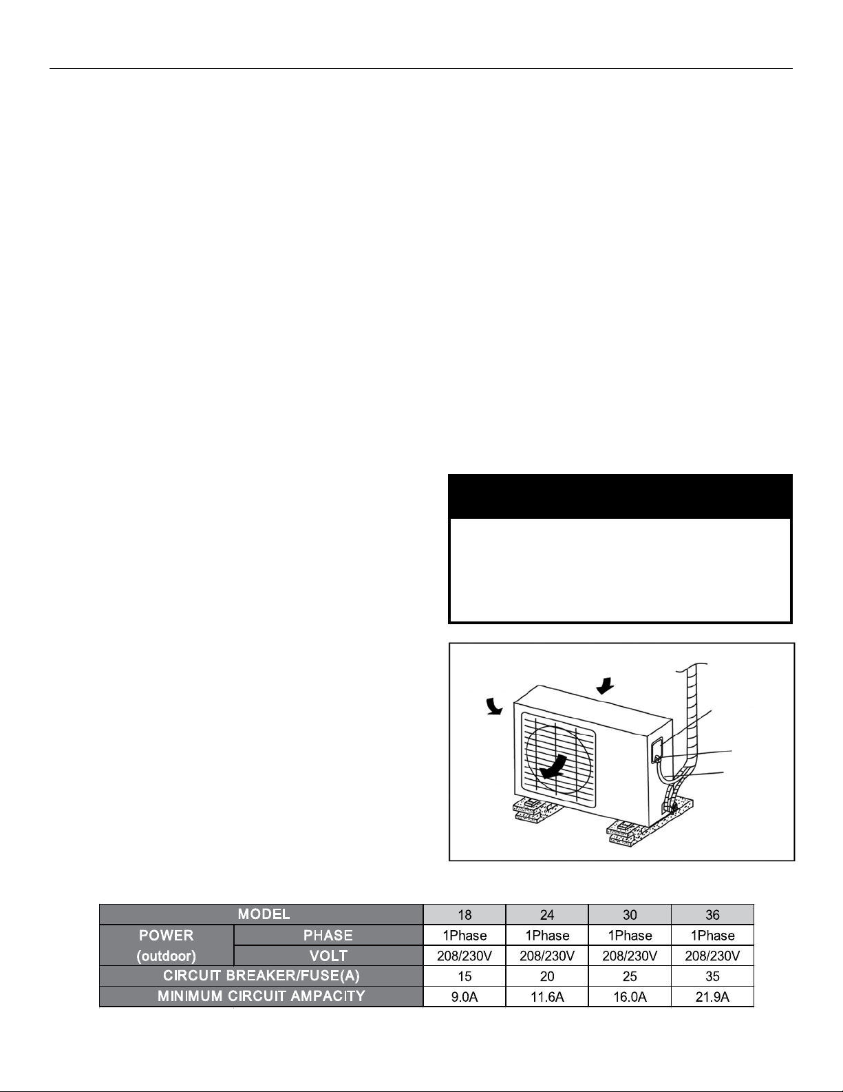
Do not locate two or more units in a way that will
block air ow or in a way that hot air from one unit
will blow into a nearby unit [See Fig. 3].
Install the outdoor unit on a rigid surface, able to
withstand the unit’s weight, such as a concrete slab.
If the installation location allows the unit to be
exposed to strong winds (such as sea side
applications), ensure that the unit has a barrier from
the wind [See Fig. 2]. This will assist with the proper
operation of the fan by obstructing strong gusts of
wind from entering the unit’s cabinet.
Avoid areas where water, snow, or ice may fall
from a roof onto the unit. In climates where snow
is a consideration, locate the unit away from areas
prone to drifting. Ensure the location of the unit will
not be subject to snow drifts, heavy accumulation
of snow or leaves or other seasonal debris. If
unavoidable, provide the awning for the unit.
6
Page 7

Heat Controller Horizontal/Side Discharge Condensing Units
OUTDOOR UNIT INSTALLATION continued
Clearances
1. Ensure that there is sufcient clearance
around the unit for installation and maintenance.
Clearance must be maintained to ensure that the
air inlets and outlets are not obstructed.
[See Fig. 4].
Anchor the outdoor unit with a 10mm (3/8 inch)
diameter bolt and nut tightly on a concrete or
rigid surface [See Fig. 5]. Anchoring is especially
recommended in seaside/high wind applications
and/or areas prone to earthquakes.
1. Split type outdoor unit clearances
Fig. 4
1. Split type outdoor unit dimensions
Fig. 5
LQFK
LQFK
LQFK
LQFKHV
Units in inches
7
Page 8
Horizontal/Side Discharge Condensing Units Heat Controller
UNIT WIRING
ELECTRICAL WIRING
AND SUPPLY VOLTAGE:
All electrical wiring must be done according to
NEC and local codes. Nameplate data indicates
the operating voltage, phase, ampacity, maximum
over current protection, and minimum voltage.
The contractor is to provide an individual branch
circuit for over current protection for the unit as
required by code. Run power supply wiring through
a weatherproof disconnect box and conduit to the
unit connection. Disconnects are required to be
within sight and easy reach of the unit (usually
within 3 feet).
Check the unit wiring diagram for the number of
conductors required. Route neatly and protect from
sharp edges and damage.
Inadequate wiring and/or improper electrical
supply will likely result in failure of the compressor
and other electrical components and voids the
warranty.
NOTE: The supply voltage must be consistent
with the rated voltage of the air conditioner, not
to exceed +/- 10%. Ensure the unit is properly
grounded.
Outdoor unit wiring connection
1. Remove the electrical control cover from the
outdoor unit.
2. Connect the cables to the terminals as
identied with their respective designated
terminal spaces on the terminal block of indoor
and outdoor units. 600V THHN 14 AWG/4
conductor unshielded stranded copper cable
is recommended, however NEC/local codes
prevail.
3. To prevent the entrance of water into outdoor
unit, form a loop in the cable [See Fig. 6].
4. Insulate any unused conductors with PCV/
Electrical tape, so that they do not touch any
other exposed electrical or metal parts.
CAUTION
Incorrect wiring connections may cause
electrical parts to malfunction. All wiring must
comply with local and national electrical
codes and be installed by qualied and skilled
electricians.
8
Page 9
Heat Controller Horizontal/Side Discharge Condensing Units
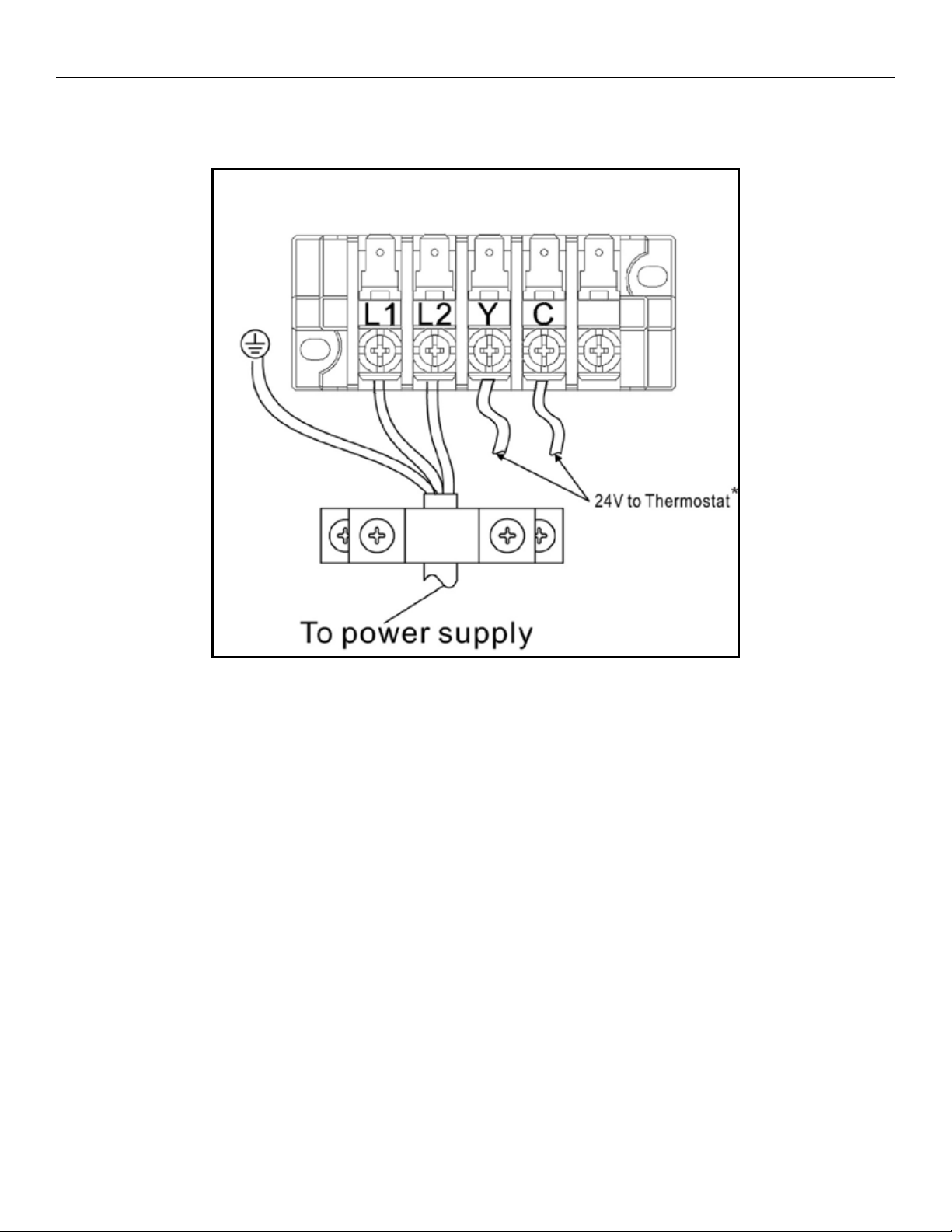
OUTDOOR UNIT WIRING CONNECTION continued
TERMINAL bLOCk OF OUTDOOR UNIT
*NOTE: Please refer to the installation instructions of the 24V
thermostat used in conjunction with this unit for additional wiring
instructions.
9
Page 10

Horizontal/Side Discharge Condensing Units Heat Controller
OUTDOOR UNIT WIRING CONNECTION continued
CMA18SB-1 & CMA24SB-1
CMA30SB-1
CMA36SB-1
10
Page 11

Heat Controller Horizontal/Side Discharge Condensing Units
REFRIGERANT PIPING
The length of refrigerant lines and the number of
bends determine the pressure drop which affects
capacity and efciency of the system and oil return
to the compressor. The outdoor unit connections
are are type. Tube size should always be the
same diameter as the connections provided at
the service valves. Up sizing of lines can result
in inadequate oil return to the compressor and
excessive refrigerant charge and will void the
warranty [See Table 1].
Refrigerant Piping
Liquid-Gas In. 1/4 - 1/2 3/8 - 3/4
Max. Refrigerant
Line Length*
Max. Elevation
Vertical Lift**
*Minimum pipe length must not be less that 15 feet.
** “P” trap risers every 10 ft. when outdoor unit is installed
above indoor unit.
Choose a location that places the condensing
unit as close to the indoor unit as possible. The
maximum separation is dependent on model.
Use only clean refrigeration grade tubing. Avoid
piping on wet or rainy days. Always keep the tube
ends capped until you are ready to make the nal
connections. Remove burrs from cut ends of tubing.
Use tube benders to avoid kinking.
Insulate the suction line with Armaex or equivalent
with a wall thickness of at least 3/8”. Support the
tubing adequately to avoid sags that can trap oil.
Isolate the tubing so as not to transmit noise to the
building structure. Avoid sharp edges that could cut
the tubes. Maximum vertical lift (compressor above
evaporator) is dependent on model. Trap risers with
a ‘P’ trap every 10 feet.
CMA 18 CMA 24 CMA 30 CMA 36
Ft. 82 98
Ft. 33 49
Model No.
WARNING
It is illegal to discharge refrigerant into the
atmosphere. Use proper reclaiming methods
and equipment when working on the refrigerant
containing parts of the unit. Service should be
performed by a QUALIFIED service agency and
certied technicians.
LEAk TEST,
EVACUATION
& RELEASE OF
REFRIGERANT
The condensing unit is supplied with R-410a
charge sufcient for most matching evaporator
units. Charge must be added for interconnecting
tubing.
The unit’s service valves are shipped in the closed
position and should not be opened until nal
connections and evacuation are completed.
The recommended procedure for leak test,
evacuation, and release of refrigerant is
outlined below:
1. Complete the nal piping connections to the
indoor and outdoor units using high temperature
brazing alloy.
2. Connect a charging manifold to the service ports
provided at the service valves.
3. Pressurize the lines and evaporator with
nitrogen and leak check all connections with
soap bubbles. Repair as necessary any
faulty joints. If brazing is required be sure to
RELEASE THE NITROGEN FIRST. Re-test as
needed.
4. Connect a vacuum pump to the manifold center
connection, start the pump and open the
manifold valves.
5. Evacuate to 500 microns or less for a minimum
of 30 minutes. Close the manifold valves and
shut off the pump. Note the vacuum reading and
wait 15 minutes. Take a new vacuum reading. A
reading of 800 microns or higher indicates the
presence of moisture or a leak.
6. Repair as necessary and repeat steps 3, 4 & 5.
7. Conrm that manifold valves are closed and
disconnect the vacuum pump.
8. Remove the caps from the services valves.
Open the valves to the fully ‘back-seat’ position.
Replace service valve caps and tighten.
11
Page 12

Horizontal/Side Discharge Condensing Units Heat Controller
INITIAL START-UP & CHECkS
Operation of the unit is automatic and will provide
cooling depending on the setting of the thermostat.
IMPORTANT!
All panels must be installed, main power turned
on and the thermostat properly connected before
operating the unit.
1. System check - set thermostat system switch to
“Off” position and fan switch to “Auto” position.
Turn the power supply breaker on.
2. Set the fan switch to “On,” blower should
operate.
3. Return the fan switch to “Auto”. Blower should
shut off. Set the system switch to “Cool” and
lower thermostat set point to coldest setting.
The compressor, condenser fan, and evaporator
blower should all come on. Cool air will be
supplied after a couple of minutes of run time.
4. Proceed to the “FIELD CHARGING” section of
these instructions.
FIELD CHARGING
Unit performance, efciency, and life depends,
to a large extent, on a proper system charge.
Time spent on getting the charge right at start-up
will payoff in the long run. Operating conditions
such as voltage, air ow, evaporator coil size,
and indoor and outdoor temperature and humidity
all have an effect on the system pressures and
superheat conditions.
FINAL INSPECTION
Do a nal visual inspection of the entire installation
and complete any nal details and clean up.
Review Unit Operation with the homeowner/user.
The pressure/temperature chart can be used as a
reference to ensure performance.
2XWGRRU$PELHQW7HPSHUDWXUH963UHVVXUH
2XWGRRU7HPSHUDWXUH
36,
1RWH³,'7´ ,QGRRU7HPSHUDWXUH
³2'7´ 2XWGRRU7HPSHUDWXUH
5HPRYHUHIULJHUDQWLIWKHSUHVVXUHLVDERYHWKHFKDUWYDOXH
$GGUHIULJHUDQWLIWKHSUHVVXUHLVEHORZWKHFKDUWYDOXH
Charge must be added for the interconnecting
tubing. Evaporator coils require thermostatic
expansion valves. These units should be critically
charged to ensure proper performance. Some
systems may require additional charging of
refrigerant, depending on line set lengths.
12
R(oz): Additional refrigerant to be charged
L(ft): The length of the liquid pipe
T(oz): The quantity of the charged refrigerant
per additional foot
oz/ft
0.16 0.32
Page 13

Heat Controller Horizontal/Side Discharge Condensing Units
4/2014
Design, material, performance specications and components
subject to change without notice.
:HOOZRUWK$YH-DFNVRQ0,3KZZZKHDWFRQWUROOHUFRP
13
 Loading...