

Page 1

OWNER’S MANUAL
Portable Dehumidier:
BHD-H Series
BHDP-H Series
R-410A
Heat Controller • 1900 Wellworth Ave. • Jackson, MI 49203 • (517)787-2100 • www.heatcontroller.com
Page 2

Owner’s Manual BHD-H/ BHDP-H Portable Dehumidier Heat Controller
CONTENTS
SAFETY PRECAUTIONS
Safety warnings and precautions ..................................................................................2
Electrical Information ..................................................................................................... 3
CONTROL PANEL
Control panel .................................................................................................................4
Other features................................................................................................................5
IDENTIFICATION OF PARTS
Identication of parts .....................................................................................................6
OPERATING THE UNIT
Positioning the unit ........................................................................................................7
Draining methods ..........................................................................................................8
CARE AND MAINTENANCE ...................................................................................... 11
TROUBLESHOOTING TIPS ....................................................................................... 12
1
Page 3

Heat Controller BHD-H/ BHDP-H Portable Dehumidier Owner’s Manual
Do not block the air intake
or exhaust openings.
A lack of air flow can lead
to overheating and fire.
Never insert your finger or
other foreign objects into grills
or openings. Take special care
to warn children of these
dangers.
!
Operation without filters
may cause failure.
Always insert the filters
securely. Clean filter
once every two weeks.
The manufactures nameplate is located on the rear panel of the unit and contains electrical and other
technical data specific to this unit.
Be sure the unit is properly grounded. To minimize shock and fire hazards, proper grounding is important.
The power cord is equipped with a three-prong grounding plug for protection against shock
hazards.
Your unit must be used in a properly grounded wall receptacle. If the wall receptacle you intend to use is
not adequately grounded or protected by a time delay fuse or circuit breaker, have a qualified electrician
install the proper receptacle.
Do not use extension cords or an adapter plug with this unit.
To avoid the possibility of personal injury, always disconnect the power supply to the unit, before cleaning
and/or servicing.
Elec t rical In for m atio n
It may cause electric shock
or failure of appliance.
SAFETY PRECAUTIONS
To prevent injury to the user or other people and property damage, the following instructions must be
followed. Incorrect operation due to ignoring of instructions may cause harm or damage.
The seriousness is classified by the following indications.
instructions may cause harm or damage.
WARNING
CAUTION
This symbol indicates the possibility of death or serious injury.
This symbol indicates the possibility of injury or damage to property.
Meanings of symbols used in this manual are as shown below.
Never do this.
Always do this.
WARNING
Do not exceed the
circuit rating.
Otherwise, it may cause electric
shock or fire due to excess heat
generation.
Do not modify power cord
length or share the outlet
with other appliances
It may cause electric shock or
fire due to heat generation.
Do not operate or stop the
unit by disconnecting the
plug from the outlet.
It may cause electric shock or fire
due to heat generation.
Do not plug/unplug the
unit with wet hands.
It may cause electric shock.
Do not damage or use an
unspecified power cord.
It may cause electric shock or fire.
Do not place the unit near
a heat source.
Plastic parts may melt and cause
a fire.
!
Disconnect the power if
strange sounds, smells, or
smoke comes from the unit.
It may cause fire and electric
shock.
It may cause failure of machine
or electric shock.
Do not use the unit near flammable
gas or combustibles, such
as gasoline, benzene, thinner, etc.
It may cause an explosion or fire.
It contains contaminants and
could make you sick.
Do not use the unit in small
spaces.
Lack of ventilation can cause
overheating and fire.
You should never try to take
apart or repair the unit by
yourself.
Do not drink or use the
water drained from the unit.
CAUTION
Do not put in places where
water may splash onto the
unit.
Water may enter the unit and
degrade the insulation. It may
cause an electric shock or fire.
!
Before cleaning, turn off
the power and unplug the
unit.
It may cause electrical shock or
injury.
Do not take the water bucket out during operation.
It may cause bucket full protect of
the unit and cause electric shock.
!
Place the unit on a
level, sturdy section
of the floor.
If the unit falls over, it may
cause water to spill and
damage belongings, or
cause electrical shock or
fire.
2
Page 4

Owner’s Manual BHD-H/ BHDP-H Portable Dehumidier Heat Controller
SAFETY PRECAUTIONS
CAUTION
!
Do not block the air intake
or exhaust openings.
A lack of air flow can lead
to overheating and fire.
Care should be taken when
using the unit in a room with
the following persons:
Infants, children, elderly people,
and people not senstive to
humidity.
Do not use in areas
where chemicals are
handled or stored.
This will cause the unit
deterioration due to
chemicals and solvents
dissolved in the air.
Never insert your finger or
other foreign objects into grills
or openings. Take special care
to warn children of these
dangers.
It may cause electric shock
Do not place heavy objects on the
power cord and take care so that
the cord is not compressed.
There is danger of fire or
electric shock.
Do not climb up on
or sit on the unit.
You may be injured if you
fall or if the unit falls over.
or failure of appliance.
!
!
Always insert the filters
securely. Clean filter
once every two weeks.
Operation without filters
may cause failure.
If water enters the unit, turn
the unit off and disconnect the
power , contact a qualified
service technician.
It may cause failure of
appliance or accident.
Do not place objects
on top of the unit.
Water may spill inside the
unit, causing insulation
failure and electrical
shock or fire.
Ele c tric a l Info r m ation
The manufactures nameplate is located on the rear panel of the unit and contains electrical and other
technical data specific to this unit.
Be sure the unit is properly grounded. To minimize shock and fire hazards, proper grounding is important.
The power cord is equipped with a three-prong grounding plug for protection against shock
hazards.
Your unit must be used in a properly grounded wall receptacle. If the wall receptacle you intend to use is
not adequately grounded or protected by a time delay fuse or circuit breaker, have a qualified electrician
install the proper receptacle.
Do not use extension cords or an adapter plug with this unit.
To avoid the possibility of personal injury, always disconnect the power supply to the unit, before cleaning
and/or servicing.
3
Page 5

Heat Controller BHD-H/ BHDP-H Portable Dehumidier Owner’s Manual
CONTROL PANEL
BHDP Models with built-in pump: BHD Models without built-in pump:
1A
Fig. 1
When you push the button to change operation modes,
the unit will make a beep sound to indicate it received the command.
Pump Operation (Models with built-in pump only)
Press to activate pump operation. (See. Fig. 1)
NOTE: Ensure the pump drain hose is installed
onto the unit, the continuous drain hose is removed and plug
is reinstalled before the pump operation is activated. When
the bucket is full,the pump starts to work. Do not use the
pump feature when the outdoor temperature is equal to or
less than (32°F) 0°C.
1B
Continuous Dehumidifying Operation
For models with out built-in pump, continuous operation
is activated by pressing the CONT. button on the control
panel. (See. Fig. 1).This allows the dehumidier to run
continuously at 35% RH (relative humidity) without cycling
the compressor and fan on and off when the desired
humidity set point is achieved. By continuously running
the fan and compressor, constant dehumidication occurs,
which achieves the maximum moisture removal from the air.
2
Filter
The check lter feature is a reminder to clean the Air Filter
for more efcient operation. The Filter light (clean lter light)
will illuminate after 250 hours of operation to remind you to
clean the lter. After cleaning the lter, press the Filter pad
and the light will go off.
3
Fan
Controls the fan speed. Press to select Turbo or Normal fan
speed. Set the fan control to Turbo for maximum moisture
removal. When the humidity has been reduced or quieter
operation is preferred, set the fan speed to Normal. For
models without pumps, the Turbo or Normal indicator lights
will display for the corresponding fan speed. For models
with built in pump, the Turbo indicator light will display when
Turbo fan speed is selected. The Turbo indicator light will
be off when the fan is in Normal mode. There is an audible
difference between Turbo and Normal speeds.
1B
41A
Power Pad
Press to turn the dehumidier on and off
567
UP/DOWN BUTTONS
Humidity Set Point Control
The humidity level can be set within a range of 35%RH
(Relative Humidity) to 85%RH (Relative Humidity) in 5%
increments. For drier air, press the - pad and set to a lower
percent value(%). For damper air, press the + pad and set
a higher percent value(%)
TIMER Set Time
Use the Up/Down pads to set the Auto start and Auto stop
time from 0.0 to 24 hours. See Timer below.
Continuous Operation Light (See. Fig. 1)
To run the unit in continuous mode, press the button until
the display reads 35% RH. Then press the - button again
until the display reads CO for continuous operation. To
stop continuous operation, press the + button and set the
desired relative humidity level to resume nominal operation.
NOTE: See 1B for a description of the continuous operation
feature.
8
TIMER
Press to initiate the Auto start and Auto stop feature, in
conjunction with the + and - key pads to set the start are
stop time.
- +
Fig. 2
4
Page 6

Owner’s Manual BHD-H/ BHDP-H Portable Dehumidier Heat Controller
Display
8
Shows the set % relative humidity level from 35% to
85% or the auto start/stop time (0~24 hours) as it is
being set. Also shows the actual room humidity level
in a range of 30% RH (Relative Humidity) to 90%RH
(Relative Humidity) with an accuracy of +5%.
Error Codes and Protective Features:
AS- Humidity sensor error--Unplug the unit and plug it
back in. If error repeats, call for service.
ES- Temperature sensor error-- Unplug the unit and
OTHER FEATURES
Bucket Full Light
Illuminates when the bucket is ready to be emptied, or when
the bucket is removed or not seated in the proper position.
Auto Shut Off
The dehumidier shuts off after 30 seconds when the
bucket is full, or when the bucket is removed or not
seated in the proper position. When the set humidity is
reached, the unit will shut off automatically. For some
models, the fan motor will continue operating. Exception
Does not apply in continuous operation.
Auto Defrost
When frost builds up on the evaporator coils, the
compressor will cycle off and the fan will continue to run
until the frost disappears.
Wait 3 minutes before resuming operation
After the unit has stopped, it can not be restarted in the
rst 3 minutes. This is to protect the unit. Operation will
automatically occur after 3 minutes.
Check lter feature
The system starts to count the time once the fan motor
operates. The check lter feature can be only activated
when the accumulated operation time achieves 250
hours or more. The Reset light(Clean lter indicator
light) ashes one time per second. After cleaning the air
lter, press the Filter pad to turn the lter light (clean lter
indicator light) off the time resets.
Turbo Light
Illuminates when the fan speed is set up to Turbo mode.
plug it back in. If error repeats, call for service.
P2- Bucket is full or bucket is not in right position-Empty the bucket and replace it in the right position.
Eb- The bucket has been removed from the unit or
is not in the right position. Replace or reposition the
bucket properly.
EC- Unit malfunction--Ensures the unit is operating
within the design parameters for temperature. If this
error occurs, turn off the unit and turn on again to
reset. If this error occurs after powering off and back
on call for service.
Auto-Restart
If the unit turns off unexpectedly due to power outage,
it will restart with the previous function setting automatically when the power resumes.
Setting the Timer
• When the unit is on, rst press the Timer button, the
Timer Off indicator light illuminates. It indicates the
Auto Stop program is initiated. Press it again the Time
On indicator light illuminates. It indicates the Auto Start
is initiated.
• When the unit is off, rst press the Timer button, the
TIMER ON indicator light illuminates. It indicates the
Auto Start program is initiated. Press it again the Time
Off indicator light illuminates. It indicates the Auto Stop
is initiated.
• Press or hold the UP or DOWN pad to change the Auto
time by 0.5 hour increments, up to 10 hours, then at 1
hour increments up to 24 hours. The control will count
down the time remaining until start.
• The selected time will register in 5 seconds and the
system will automatically revert back to display the
previous humidity setting.
• When the Auto start & Auto stop times are set,
within the same program sequence, TIMER ON OFF
indicator lights illuminate identifying both ON and OFF
times are now programmed.
• Turning the unit ON or OFF at any time or adjusting
the timer setting to 0.0 will cancel the Auto Start/Stop
function.
• When LED display window displays the code of P2,
the Auto Start/Stop function will also be cancelled.
Normal Light
NOTE: Applies to models without built-in pump only.
Illuminates when the fan speed is set to normal, which is
low fan speed.
Continuous Light
NOTE: Applies to models with built-in pump only.
Illuminates when continuous operation is in effect.
5
Page 7
Heat Controller BHD-H/ BHDP-H Portable Dehumidier Owner’s Manual
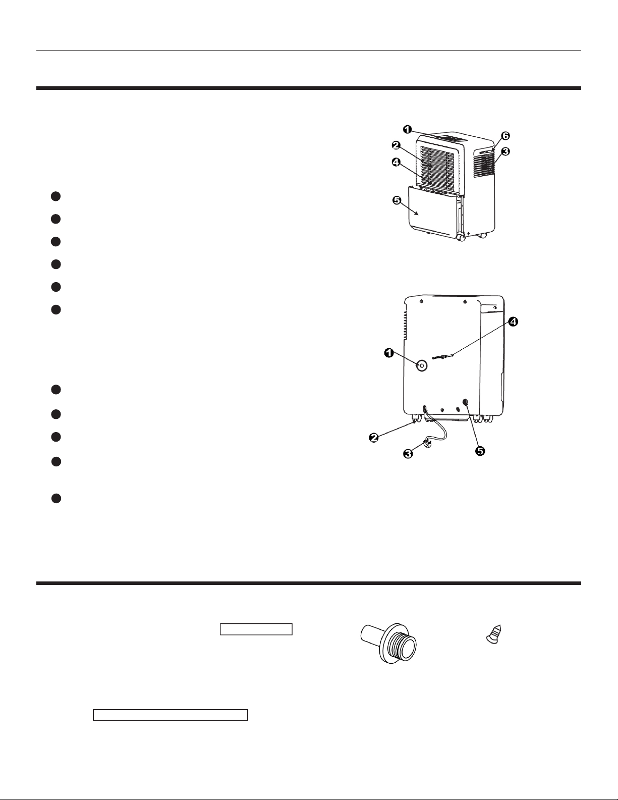
IDENTIFICATION OF PARTS
Identication of Parts
Front
1
Control panel
2
Air intake grille
3
Air outlet grille
4
Air lter (behind the grille)
5
Water bucket
6
Handle (both sides)
Fig. 3
Rear
1
Continuous drain hose outlet and plug
2
Casters
3
Power cord and plug
4
Cable Tie (to store power cord
when unit is not in use.)
5
Pump drain hose outlet
NOTE: All the pictures in the manual are for explanation purposes only. The actual shape of the
unit you purchased may be slightly different, but the operations and functions are the same.
ACCESSORIES
ATTENTION: Check
inside the bucket and
the packaging for
these accessories.
Hose Segment (1pc)
required for pump models only
to use during pump operation
Hose Segment (1pc)*
Pump Drain
Continuous Drain
required to bypass
bucket for gravity drain
Fig. 4
Adapter A (1pc)* Screw (2pc)
required for
continuous
drainage
*NOTE: Some models will have the continuous
drain hose and adapter already assembled together.
Other models will require you to attach the drain
hose to the adapter.
6
Page 8

Owner’s Manual BHD-H/ BHDP-H Portable Dehumidier Heat Controller
OPERATING THE UNIT
Positioning the Unit
A dehumidier operating in a basement will have little or no
effect in drying an adjacent enclosed storage area, such as a
closet, unless there is adequate circulation of air in and out of
the area.
• Do not use outdoors.
• This dehumidier is intended for indoor residential
applications only. This dehumidier should not be used
for commercial or industrial applications.
• Place the dehumidier on a smooth, level oor strong
enough to support the unit with a full bucket of water.
• Allow at least 8 inches of clearance on all sides of
the unit and 15 inches above the unit for good air circulation.
(See Fig. 5).
• Place the unit in an area where the temperature will not
fall below 41°F (5°C). The coils can become covered with
frost at temperatures below 41°F (5°C), which may reduce
performance.
• Models with pumps should not operate when the
temperature is 32°F (0°C) or below to prevent condensate
from freezing inside the drain hose and damaging the pump.
• Place the unit away from sources of heat such as clothes
dryer, heater or radiator.
• Use the unit to prevent moisture damage anywhere books
or valuables are stored. Use the dehumidier in a basement
to help prevent moisture damage.
• The dehumidier must be operated in an enclosed area to be
most effective.
• Close all doors, windows and other outside openings to the
room.
Fig. 5
When using the Unit
• When rst using the dehumidier, operate the unit
continuously 24 hours.
• This unit is designed to operate with a working environment
between 41°F (5°C) and 95°F(35°C).
• If the unit has been switched off and needs to be switched
on again quickly, allow approximately three minutes for
operation to resume.
• Do not connect the dehumidier to an electrical outlet, which
is also being used for other electrical appliances.
• Select a suitable location, making sure you have easy
access to an electrical outlet.
• Plug the unit into a electrical socket-outlet with a proper
ground connection.
• Make sure the Water bucket is correctly seated in
position otherwise the unit will not operate properly.
7
Page 9
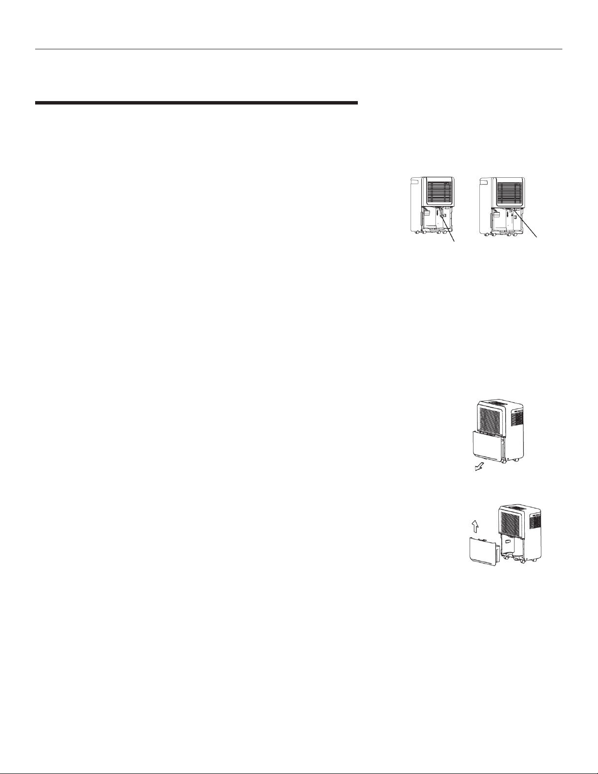
Fig. 5
Heat Controller BHD-H/ BHDP-H Portable Dehumidier Owner’s Manual
2. Hold both sides of the bucket with even strength,
and pull it out from the unit.
OPERATING THE UNIT
Condensate Removal
There are several ways to remove collected condensate.
1 By emptying the bucket each time it’s full.
2. By continuously draining through a hose into a drain.
3. By pumping water out of the bucket through a hose into a drain
(pump only models).
NOTES:
• When you remove the bucket, do not touch any parts inside of the unit.
Doing so may damage the product or cause injury.
• Be sure to push the bucket gently all the way back into the unit.
• If the pump suction line drops down when you remove the bucket (See Fig.
6), you must push the pump’s suction line back up toward the top of the
cavity where the bucket resides before replacing the bucket (See Fig. 7).
• When the continuous drain feature is not being used, remove the drain hose
from the outlet and reinstall the plug.
• When the pump feature is not being used, remove the pump drain hose.
• The bucket has a oat switch inside, which is a plastic part with styrofoam in
it. Be sure this is also in it’s proper position upon reinstalling the bucket.
3. Discard the condensate
water from the bucket.
Pump suction line
drops down
Drain Hose Segment
Continuous Drain Plug
Fig. 6
Fig. 7Fig. 6
Reinstall pump
hose properly
Adapter A
Fig. 9
1. Condensate Collection Bucket
• The dehumidier will alert you when it is time to empty the bucket.
• If the bucket is full when the unit is off and you attempt to turn it on, the
unit will beep 8 times and the Full indicator light will ash, the display
will show the P2 error code.
• When the unit is operating and the bucket becomes full, the
compressor turns off 30 seconds later the fan turns off. The unit will
beep 8 times and the Full indicator light will ash, the display will show
the P2 error code.
• Slowly pull out the bucket. Grip the handles securely, and carefully pull
the bucket straight out of the unit so the water does not spill. Do not
set the bucket on the oor because the bottom of the bucket is uneven,
which may cause the bucket to tip and the water to spill. (Fig. 8).
• Discard the water and replace the bucket in to the unit. (Fig. 9). The
bucket must be securely seated for the dehumidier to operate. If the
bucket is not properly installed a P2 or Eb error code will display on the
control panel.
• The dehumidier will re-start when the bucket is restored to its correct position.
Drain Hose segment
attached to Adapter A
1. Pull out the bucket a little.
Fig. 10
Fig. 8
2. Hold both sides of the bucket with even strength,
Connector
and pull it out from the unit.
Drain Hose
Garden Hose
3. Discard the condensate
water from the bucket.
Female thread end
Fig. 11
Fig. 9
Fig. 12
Fig. 8Fig. 7
Pump suction line
drops down
Drain Hose Segment
8
Reinstall pump
hose properly
Adapter A
Fig. 9
Page 10

3. Discard the condensate
water from the bucket.
Fig. 6
Owner’s Manual BHD-H/ BHDP-H Portable Dehumidier Heat Controller
Fig. 8Fig. 7
OPERATING THE UNIT
2. Condensate Drainage (gravity drainage)
• Water can be automatically emptied into a oor drain by attaching
the unit with a water hose, a standard garden hose to the
unit. The garden hose is not supplied with the unit, but can be
purchased separately from a local hardware store.
• Push the drain hose segment onto the hose barb Adapter A
(See Fig. 10).
NOTE: Some models may not require this step.
• Remove the continuous drain plug from the outlet on the back of
the unit. (See Fig. 11).
• Remove the bucket, then insert the continuous drain hose through
the continuous drain outlet of the unit so that the threaded end of
Adapter A is facing outward from the rear of the unit. While looking
into the empty cavity of the unit where the bracket normally
resides, pull the hose until you can securely slide it onto the
connector inside the cavity where the bucket resides. (See Fig.
12).
• Tighten the Adaptor A to the rear unit securely with two screws.
• Connect one end of the garden hose to the threaded end of
Adapter A (See Fig. 13). Run the other end of the garden hose to
the oor drain or a suitable drainage facility.
• Make sure the hose connections are secure, so there are no
leaks.
• Ensure that there are no kinks in the hose that will stop the water
ow.
• Ensure end of the hose is level or pointed downward to let the
water ow freely by gravity.
• Place the bucket back into the unit and make sure that it is seated
properly.
• Select the desired humidity setting and fan speed on the control
panel continuous draining to start.
Pump suction line
drops down
Drain Hose Segment
Continuous Drain Plug
Drain Hose segment
attached to Adapter A
Connector
Drain Hose
Garden Hose
Female thread end
Reinstall pump
hose properly
Adapter A
Fig. 10
Fig. 11
Fig. 12
Fig. 13
9
Page 11

Heat Controller BHD-H/ BHDP-H Portable Dehumidier Owner’s Manual
OPERATING THE UNIT
3. Condensate Pump Drainage
Water can be automatically emptied into a oor drain or a suitable
drainage location by attaching the factory supplied pump drain hose
(0od=1/4”) to the pump drain outlet on the rear of the unit.
• Before activating the condensate pump, ensure that the garden hose,
continuous drain hose and Adapter A subassembly are removed from
the unit. Be certain that the continuous drainage outlet is plugged
securely. (See Fig. 14).
• Next insert the factory supplied pump condensate hose into the pump
discharge outlet. Ensure that the connection is secure to prevent water
leaks by slightly tugging on the hose gently. (See Fig. 15).
• Direct the opposite end of the pump’s drain hose toward the oor drain
or other suitable drainage location, ensuring that there are no kinks in
the hose to obstruct condensate drainage. Ensure that the end of the
hose is level or directed downward into the drain for proper drainage.
• Press the button labeled pump on the control panel, then select the
desired relative humidity level and fan speed to activate the pump.
When the bucket is full, the pump will begin to operate . NOTE: The
pump may sound noisy when it starts to work for the rst 3-5 minutes.
This is a normal phenomenon.
ATTENTION: If the pump operation light blinks when the pump is
operational, this means there is a problem with the pump feature that
requires trouble shooting. CHECK THE FOLLOWING:
• Ensure the pump’s strainer is not clogged. To check the strainer and/or
unclog it. Remove the bucket. Simply pull down the condensate pump’s
inlet hose. The strainer is a small screened cup, which can easily twist
off to be cleaned. Remove only debris from the screen of the strainer
and twist it back on the pump inlet hose. Push the pump inlet hose
back into the proper position and re-install the bucket. (See Fig. 16).
• Check that the pump’s drain hose is not kinked or has anything
blocking the condensate from draining.
• Turn on the unit. Ensure the bucket is empty, then re-install it. Be
certain it is properly seated.
• Turn off the unit, then turn on again. If the error repeats, call for service.
CAUTION:
• Do not use the pump feature when the outdoor temperature is equal
to or less than 32°F (0°C), otherwise condensate may freeze inside
the pump’s drain line, blocking condensate removal and possibility
damaging the pump. Make sure to empty the bucket once a week when
using the pump drainage feature.
• When the pump drainage feature is not being used, remove the
pump drain hose from the outlet by pushing the pump’s drain outlet
connection toward the cabinet while pulling the pump drain hose
outward, away from the cabinet. (See Fig. 17).
Continuous Drain Plug
Garden Hose,
continuous drain hose
segment and Adapter A
Fig. 15
2
Pull the pump
drain hose away
from the cabinet
Fig. 14
Pump Drain OutletPump Drain Hose
Fig. 16
Pump Inlet Hose
with Strainer
Fig. 17
Push the connector
1
toward the cabinet
10
Page 12

Owner’s Manual BHD-H/ BHDP-H Portable Dehumidier Heat Controller
CARE AND MAINTENANCE
Care and cleaning of the dehumidier
Turn the dehumidier off and remove the plug from the
wall outlet before cleaning.
1. Clean the Grille and Cabinet
• Use water and a mild detergent. Do not use bleach or abrasives.
• Do not splash water directly into the unit. Doing so may cause an
electrical shock, cause the insulation to deteriorate, or cause the unit
to rust.
• The air intake and outlet grilles may become clogged with dust, so
use a vacuum attachment with brush to clean.
.
2. Clean the Bucket
• Every few weeks, clean the bucket to prevent growth of mold, mildew
and bacteria. Partially ll the bucket with clean water and add a little
mild detergent. Swish it around in the bucket, empty and rinse.
After cleaning, the bucket must be reinstalled and securely seated for
the dehumidier to operate.
WARNING: Do not use a dishwasher to clean the bucket.
3. Clean the Air Filter
• Remove the lter at least every two weeks for cleaning or more
frequently if needed.
• Remove bucket then pull lter downwards (See Fig. 18).
• Wash the lter with clean water then air dry.
• Once lter is completely dry, re-install it and the bucket.
CAUTION: DO NOT operate the dehumidier without a lter because
the dirt and lint will clog the coils and reduce performance.
4. Clean the Pump Strainer (for models with pumps only)
• Remove the bucket.
• Simply pull down the pump inlet hose inside the empty cavity where
the bucket resides (See Fig. 19).
• The strainer is a small screened cap, which can easily twist off for
cleaning.
• Remove any debris from the screen of the strainer and twist back on
to the pump inlet hose.
• Push the inlet hose back into it’s proper position, then reinstall the
bucket.
5. When not using the unit for long time periods
• After turning off the unit, wait one day before emptying the bucket to
be sure all condensate on the coils has drained.
• Clean the main unit, water bucket and air lter.
• Unplug the power cord and bundle it using the cable tie (Fig. 20).
• Store the unit upright in a dry, wall-ventilated place until ready to use
again.
Fig. 18
Pump Strainer
Fig. 19
11
Fig. 20
Page 13

Heat Controller BHD-H/ BHDP-H Portable Dehumidier Owner’s Manual
TROUBLESHOOTING TIPS
Before calling for service, review the chart below to see if you can resolve the issue yourself. This
step can potentially save you time and money.
What to checkProblem
• Make sure the dehumidier’s plug is pushed completely
Unit does not start
Dehumidier does not
dry the air as it should
into the outlet.
• Check the fuse/circuit breaker box.
• Dehumidier has reached its preset level or bucket is full.
• Water bucket is not seated in the proper position.
• Allow enough time to remove the moisture.
• Make sure there are no curtains, blinds or furniture blocking the
air inlets/outlets of the dehumidier.
• Try lowering the set point of the RH%.
• Check that all doors, windows and other openings are securely closed.
• Ensure the unit is not operating outside of its normal operating
conditions, below 41°F (5°C).
• Ensure no other products are used in the room where the
dehumidier is operating, which give off water vapor, such as a
kerosene heater.
The unit makes a loud
noise when operating
Frost appears
on the coils
Water on the oor
ES, AS, PS, EC, or Eb
appear on the display
• Unclog the air lter.
• Ensure the unit is sitting on a level surface, to prevent
vibration
• This is normal. The dehumidier has on Auto defrost
feature, which will automatically de-ice the coils as needed.
• Ensure drain hoses and/or plugs are properly installed.
• Be sure drain hoses do not have kinks or blockages.
• These are error codes and protection code. See the
CONTROL PANEL section for more details related to what
each error code is and how to resolve it.
12
Page 14

Owner’s Manual BHD-H/ BHDP-H Portable Dehumidier Heat Controller
This page is left intentionally blank.
13
Page 15

Heat Controller BHD-H/ BHDP-H Portable Dehumidier Owner’s Manual
This page is left intentionally blank.
14
Page 16
'XHWRRQJRLQJSURGXFWLPSURYHPHQWVVSHFLILFDWLRQVDQGGLPHQVLRQVDUH
VXEMHFWWRFKDQJHDQGFRUUHFWLRQZLWKRXWQRWLFHRULQFXUULQJREOLJDWLRQV'HWHUPLQLQJWKH
DSSOLFDWLRQDQGVXLWDELOLW\IRUXVHRIDQ\SURGXFWLVWKHUHVSRQVLELOLW\RIWKHLQVWDOOHU
$GGLWLRQDOO\WKHLQVWDOOHULVUHVSRQVLEOHIRUYHULI\LQJGLPHQVLRQDOGDWDRQWKHDFWXDOSURGXFW
SULRUWREHJLQQLQJDQ\LQVWDOODWLRQSUHSDUDWLRQV
,QFHQWLYHDQGUHEDWHSURJUDPVKDYHSUHFLVHUHTXLUHPHQWVDVWRSURGXFWSHUIRUPDQFH
DQGFHUWLILFDWLRQ$OOSURGXFWVPHHWDSSOLFDEOHUHJXODWLRQVLQHIIHFWRQGDWHRIPDQXIDFWXUH
KRZHYHUFHUWLILFDWLRQVDUHQRWQHFHVVDULO\JUDQWHGIRUWKHOLIHRIDSURGXFW
7KHUHIRUHLWLVWKHUHVSRQVLELOLW\RIWKHDSSOLFDQWWRGHWHUPLQHZKHWKHUDVSHFLILF
PRGHOTXDOLILHVIRUWKHVHLQFHQWLYHUHEDWHSURJUDPV
:HOOZRUWK$YH-DFNVRQ0,3KZZZKHDWFRQWUROOHUFRP
4/2014
 Loading...