

Page 1
Through-The-Wall
Air Conditioning
Important Information
• Please read carefully and thoroughly this manual before operating this unit.
• Contact a qualified sevice technician for installation, repair and maintenance of this unit.
• The appliance is not intended for use by young children or those who require supervision.
• Young children should be supervised to ensure that they do not play with the appliance.
HEAT CONTROLLER, INC.
Models: BG-81A
BG-101A
BG-123A
Page 2
2 Room Air Conditioner
Window-Type Air Conditioner Owner’s Manual
TABLE OF CONTENTS
FOR YOUR RECORDS
Write the model and serial numbers here:
Model #
Serial #
You can find them on a label on the side of each unit.
Dealer's Name
Date Purchased
■ Staple your receipt to this page in the event you need it
to prove date of purchase or for warranty issues.
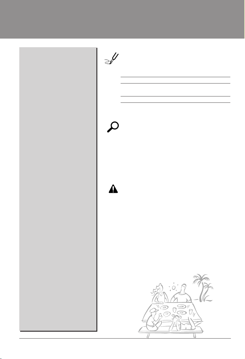
READ THIS MANUAL
Inside you will find many helpful hints on how to use and
maintain your air conditioner properly. Just a little preventive
care on your part can save you a great deal of time and
money over the life of your air conditioner.
You'll find many answers to common problems in the chart
of troubleshooting tips. If you review our chart of
Troubleshooting Tips first,youmaynotneedtocallfor
service at all.
PRECAUTION
• Contact the authorized service technician for repair
or maintenance of this unit.
• Contact the installer for installation of this unit.
• The air conditioner is not intended for use by young
children or invalids without supervision.
• Young children should be supervised to ensure that
they do not play with the air conditioner.
• When the power cord is to be replaced, replacement
work shall be performed by authorized personnel only
using only genuine replacement parts.
• Installation work must be performed in accordance
with the National Electric Code by qualified and
authorized personnel only.
Safety Precautions ..........................3
Before Operation .............................7
Introduction ....................................8
Electrical Safety ..............................9
Installation ....................................11
Operating Instructions .................18
Maintenance and Service ............21
Page 3
Owner’s Manual 3
ENGLISH
Safety Precautions
Safety Precautions
To prevent injury to the user or other people and property damage, the following instructions
must be followed.
■ Incorrect operation due to ignoring instruction will cause harm or damage. The seriousness
is classified by the following indications.
■ Meanings of symbols used in this manual are as shown below.
This symbol indicates the possibility of death or serious injury.
This symbol indicates the possibility of injury or damage to properties only.
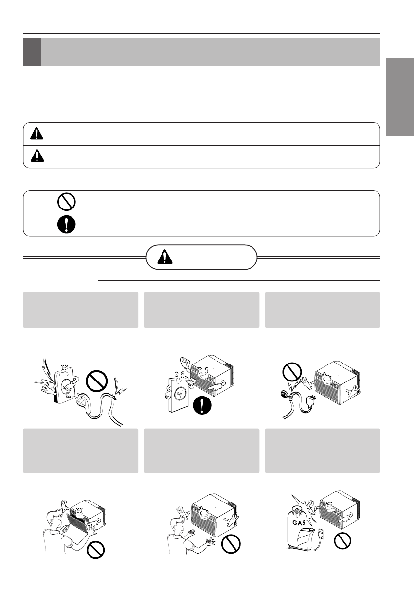
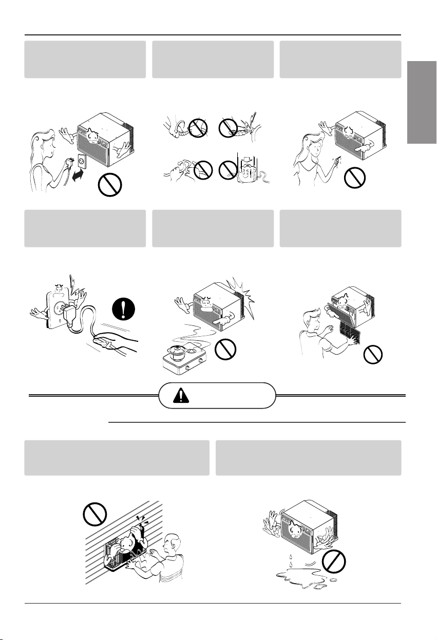
WARNING
■ Installation
Be sure not to do.
Be sure to follow the instruction.
Don’t use a power cord, a
plug or a loose socket which
is damaged.
• Otherwise, it may cause a fire
or electrical shock.
Always plug into a grounded
outlet.
• Otherwise, it may cause a fire
or electrical shock.
Do not modify or extend the
power cord length.
• It will cause electric shock or fire
due to heat generation.
Do not disassemble or
modify products.
• It may cause failure and
electric shock.
Be caution when unpacking
and installing.
• Sharp edges may cause
injury.
Do not use the power cord near
flammable gas or combustibles
such as gasoline, benzene,
thinner, etc.
• It may cause explosion or fire.
Gasolin
WARNING
CAUTION
Page 4
4 Room Air Conditioner
Safety Precautions
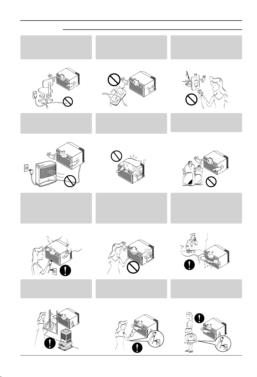
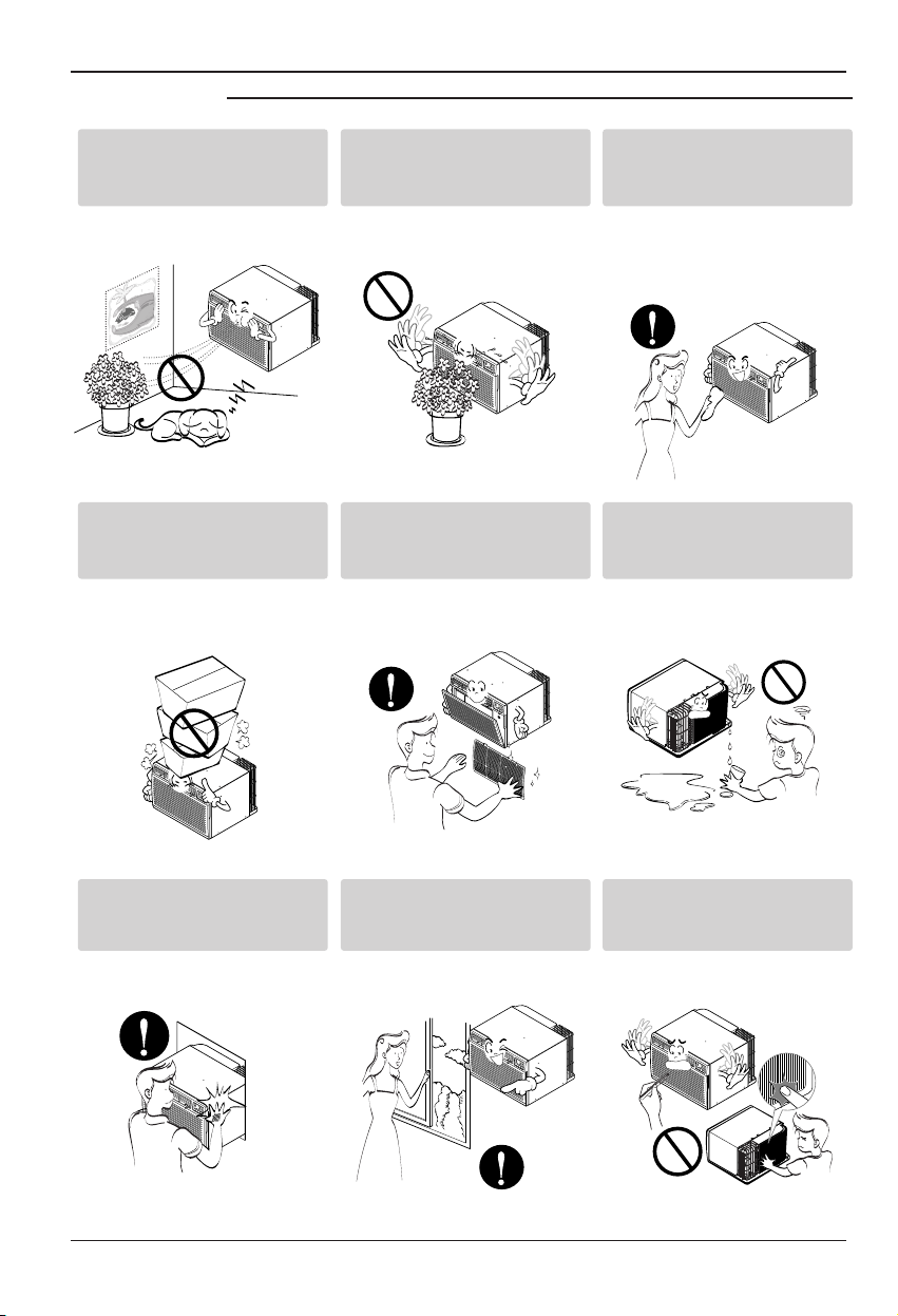
■ Operation
Do not place the power cord
near a heater.
• It may cause fire and electric
shock.
Do not allow water to run
into electric parts.
• It will cause failure of machine or
electric shock.
Use a soft cloth to clean. Do
not use wax, thinner, or a
strong detergent.
• The appearance of the air
conditioner may deteriorate,
change color, or develop surface
flaws.
Wax
Thinner
Ventilate the room well when
using this appliance
together with a stove, etc.
• An oxygen shortage may occur.
Turn off the power and
breaker firstly when
cleansing the unit.
• Since the fan rotates at high
speedduringoperation,itmay
cause injury.
Turn off the main power
switch when not using it for
alongtime.
• Prevent accidental startup and
the possibility of injury.
Unplug the unit if strange
sounds, odors, or smoke
come from it.
• Otherwise it may cause fire and
electric shock accident.
Do not open the suction
inlet grill of the product
during operation.
• Otherwise, it may electrical
shock and failure.
If water enters the product, turn
off the the power switch of the
main body of appliance. Contact
service center after taking the
power-plug out from the socket.
Do not place heavy object
on the power cord and take
care so that the cord should
not be pressed.
• Thereisdangeroffireorelectric
shock.
Do not share the outlet with
other appliances.
• It will cause electric shock or fire
due to heat generation.
Take the power plug out if
necessary, holding the head
of the plug and do not touch
it with wet hands.
• Otherwise, it may cause a fire
or electrical shock.
Page 5
Owner’s Manual 5
ENGLISH
Safety Precautions
CAUTION
■ Installation
Do not operate or stop the
unit by inserting or pulling
out the power plug.
• It will cause electric shock or fire
due to heat generation.
Do not damage or use an
unspecified power cord.
• It will cause electric shock or fire.
Do not operate with wet
hands or in damp
environment.
• It will cause electric shock.
Hold the plug by the head
when taking it out.
• It may cause electric shock and
damage.
When gas leaks, open the
window for ventilation
before operating the unit.
• Otherwise, it may cause
explosion, and a fire.
Never touch the metal parts
of the unit when removing
the filter.
• They are sharp and may cause
injury.
Install the product so that the noise or hot
wind from the outdoor unit may not cause
any damage to the neighbors.
• Otherwise, it may cause dispute with the
neighbors.
Keep level parallel in installing the product.
• Otherwise, it may cause vibration or water
leakage.
Page 6
6 Room Air Conditioner
Safety Precautions
■ Operation
Be cautious not to touch the
sharp edges when
installing.
• It may cause injury.
Avoid excessive cooling and
perform ventilation
sometimes.
• Otherwise, it may do harm to
your health.
Do not insert the hands or
bars through the air inlet or
outlet during operation.
• Otherwise,itmaycause
personal injury.
Do not put a pet or house
plant where it will be
exposedtodirectairflow.
• It may cause injury.
Do not block the inlet or
outlet of air flow.
• It may cause product failure.
Useasoftclothtoclean.Do
not use wax, thinner, or a
strong detergent.
• Theappearanceoftheair
conditioner may deteriorate,
change color, or develop surface
flaws.
Do not step on the
indoor/outdoor unit and do
notputanythingonit.
• It may cause an injury through
dropping of the unit or falling
down.
Always insert the filter
securely.
Clean it every two weeks.
• Operation without filters will
cause failure.
Do not drink water drained
from air conditioner.
• It contains containments and will
make you sick.
Page 7

Before Operation
Owner’s Manual 7
ENGLISH
Before Operation
1. Contact an installation specialist for installation.
2. Plug in the power plug properly.
3. Use a dedicated circuit.
4. Do not use an extension cord.
5. Do not start/stop operation by plugging/unplugging the power cord.
6. If the cord/plug is damaged, replace it with only an authorized replacement
part.
1. Being exposed to direct airflow for an extended period of time could be
hazardous to your health. Do not expose occupants, pets, or plants to direct
airflow for extended periods of time.
2. Due to the possibility of oxygen deficiency, ventilate the room when used
together with stoves or other heating devices.
3. Do not use this air conditioner for non-specified special purposes (e.g.
preserving precision devices, food, pets, plants, and art objects). Such usage
could damage the items.
1. Do not touch the metal parts of the unit when removing the filter. Injuries can
occur when handling sharp metal edges.
2. Do not use water to clean inside the air conditioner. Exposure to water can
destroy the insulation, leading to possible electric shock.
3. When cleaning the unit, first make sure that the power and breaker are turned
off. The fan rotates at a very high speed during operation. There is a
possibility of injury if the unit’s power is accidentally triggered on while
cleaning inner parts of the unit.
For repair and maintenance, contact your authorized service dealer.
Preparing for Operation
Usage
Cleaning and Maintenance
Service
Page 8
8 Room Air Conditioner
Introduction
This symbol alerts you to the risk of electric shock.
This symbol alerts you to hazards that could cause harm to
the air conditioner.
This symbol indicates special notes.
NOTICE
This appliance should be installed in accordance with the National Electric Code.
Introduction
Symbols Used in this Manual
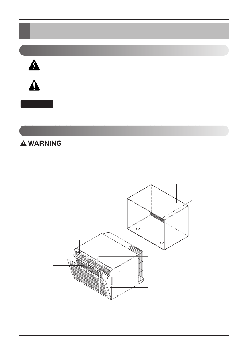
Features
THE SLEEVE AND THE REAR GRILLE
(optionally supplied with your unit)
SLEEVE ASSEMBLY
(Including Aluminum Rear grille)
AIR FILTER
INLET GRILLE
VERTICAL AIR DEFLECTOR
(Horizontal Louver)
(Air Intake)
HORIZONTAL AIR DEFLECTOR
(Vertical Louver)
REAR GRILLE
(Aluminum Rear grille)
THE UNIT
AIR DISCHARGE
CABINET
FRONT GRILLE
VENT CONTROL
Page 9
Electrical Safety
Owner’s Manual 9
ENGLISH
Electrical Safety
Electrical Data
Never push the test button during
operation
Otherwise this plug can damaged.
This device contains chemical, including
lead, known to the State of California to
cause cancer, and birth defects or other
reproductive harm.
Wash hands after handling.
Do not remove, modify or immerse this plug.
If this device trips, the cause it to be
corrected before further use.
The conductors inside this cord are
surrounded by shields, which monitor
leakage current.
These shields are not grounded.
Periodically examine the cord for any
damage. Do not use this product in the
event the shields become exposed.
Avoid shock hazard, this unit can not
be user serviced opening the tamper
resistant. Sealed portion of the unit
voids all warranties and performance
claims. This unit not intended for use
as an on-off switch.
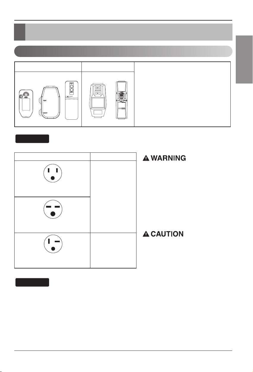
The shape may be different according to its model.
NOTICE
DO NOT USE AN EXTENSION CORD on 230,
208, and 230/208 Volt units.
All wiring should be made in accordance with local
electrical codes and regulations.
Aluminum house wiring may pose special
problems. Consult a qualified electrician.
NOTICE
115V~ 230V~
Use Wall Receptacle Power Supply
Standard 125V, 3-wire grounding
receptacle rated 15A, 125V AC
Standard 250V, 3-wire grounding
receptacle rated 15A, 250V AC
Use 15 AMP. time
delay fuse or 15 AMP.
circuit breaker.
Power cord may include a current
interrupter device. A test and reset button is
provided on the plug case. The device
should be tested on a periodic basis by first
pressing the TEST button and then the
RESET button. If the TEST button does not
trip or if the RESET button will not stay
engaged, discontinue use of the air
conditioner and contact a qualified service
technician.
Standard 250V, 3-wire grounding
receptacle rated 20A, 250V AC
Use 20 AMP. time
delay fuse or 20 AMP.
circuit breaker.
Page 10

10 Room Air Conditioner
Electrical Safety
Electrical Safety
IMPORTANT
(PLEASE READ CAREFULLY)
FOR THE USER'S PERSONAL SAFETY,THIS
APPLIANCE MUST BE PROPERLY GROUNDED
The power cord of this appliance is equipped with a
three-prong (grounding) plug. Use this with a standard
three-slot (grounding) wall power outlet to minimize the
hazard of electric shock. The customer should have the
wall receptacle and circuit checked by a qualified
electrician to make sure the receptacle is properly
grounded.
DO NOT CUT OR REMOVE THE THIRD (GROUND)
PRONG FROM THE POWER PLUG.
A. SITUATIONS WHEN THE APPLIANCE WILL BE
DISCONNECTED OCCASIONALLY:
Because of potential safety hazards, we strongly
discourage the use of an adapter plug. However, if you
wish to use an adapter, a TEMPORARY CONNECTION
may be made. Use UL-listed adapter, available from
most local hardware stores.
The large slot in the adapter must be aligned with the
large slot in the receptacle to assure a proper polarity
connection.
:
Attaching the adapter ground terminal to the wall
receptacle cover screw does not ground the appliance
unless the cover screw is metal, and not insulated, and
the wall receptacle is grounded through the house
wiring. The customer should have the circuit checked
by a qualified electrician to make sure the receptacle
is properly grounded.
Disconnect the power cord from the adapter, using one
hand on each. Otherwise, the adapter ground terminal
might break. DO NOT USE the appliance with a broken
adapter plug.
B. SITUATIONS WHEN THE APPLIANCE WILL BE
DISCONNECTED OFTEN.
Do not use an adapter plug in these situations.
Unplugging the power cord frequently can lead to an
eventual breakage of the ground terminal. The wall
power outlet should be replaced by a three-slot
(grounding) outlet instead.
USE OF EXTENSION CORDS
Because of potential safety hazards, we strongly
discourage the use of an extension cord. However, if
you wish to use an extension cord, use a CSA
certified/UL-listed 3-wire (grounding) extension cord,
rated at 15A, 125V.
Page 11
Owner’s Manual 11
ENGLISH
Installation
Installation
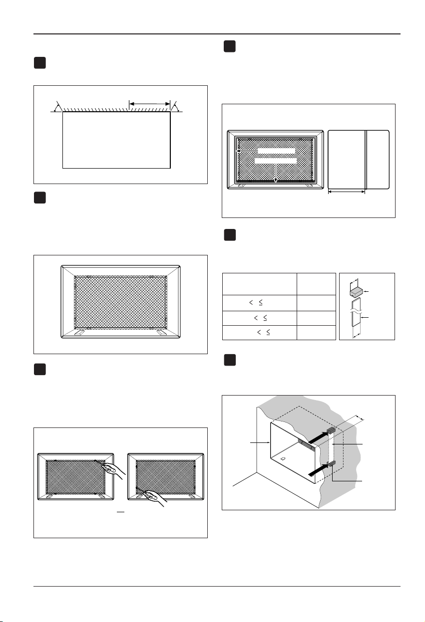
Remove packing materials from the wall sleeve and tape
from the air conditioner.
INSTALLATION REQUIREMENTS
If you use an existing wall sleeve, you should
measure its dimensions.
Install the new air conditioner according to these
installation instructions to achieve the best
performance. All wall sleeves used to mount the new
air conditioner must be in good structural condition
and have a rear grille to securely attach the new air
conditioner. (FIG. 1)
With the HCI sleeve(optionally supplied with your
unit), you can maintain the best performance of the
new air conditioner. (FIG. 2)
ELECTRICAL SERVICE
Check your available electrical service. The power
supply available must be the same as that shown on
the unit nameplate (found on left side of cabinet).
All models are equipped with a 3-prong service plug
to provide proper service and safe positive
grounding. Do not change plug in any way. Do not
use an adapter plug. If your present wall outlet does
not match your plug, call a qualified electrician to
make the necessary corrections. SAVE CARTON for
storage and this OWNER'S MANUAL for future
reference. The carton is the best way to store unit
during winter or when not in use.
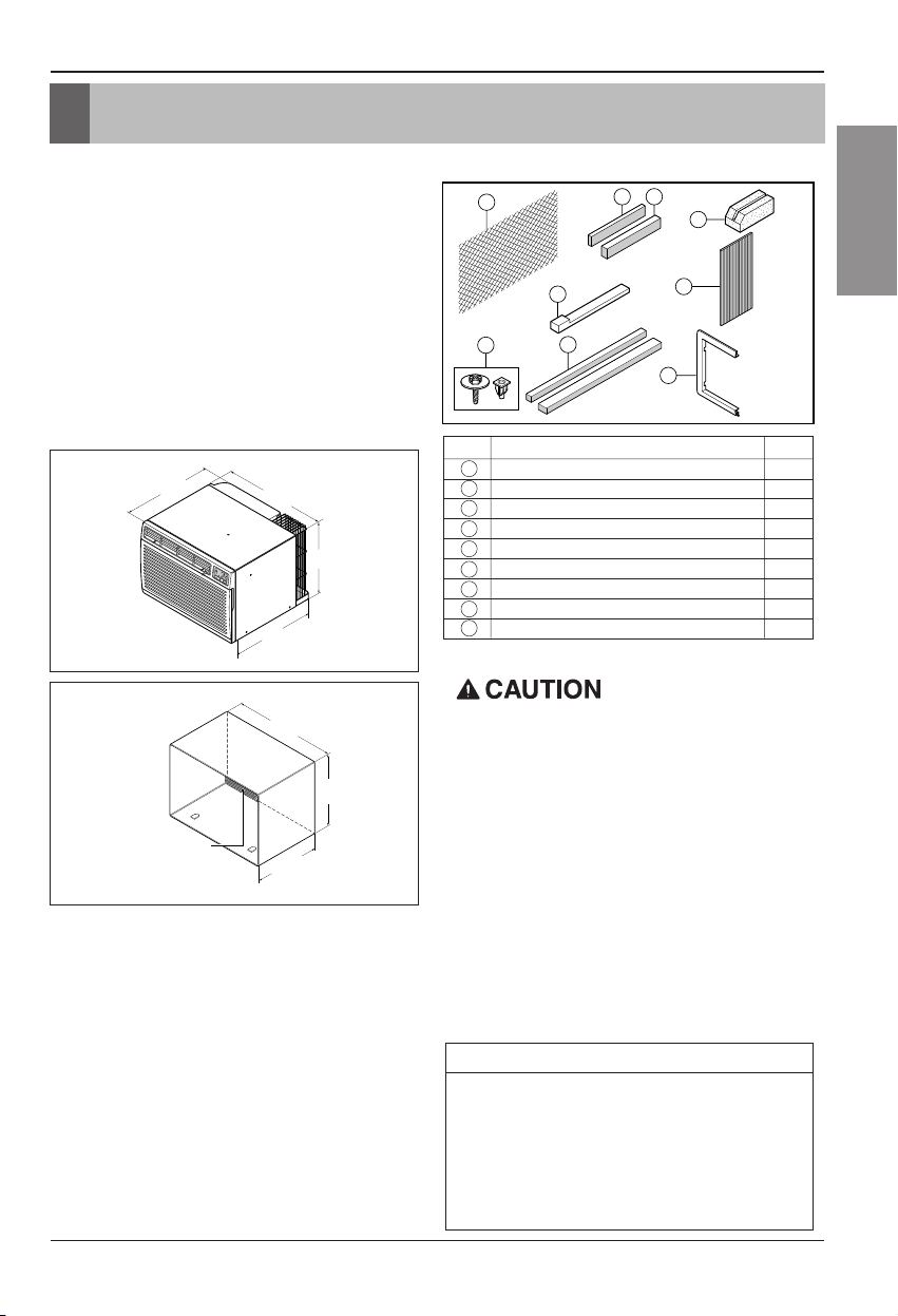
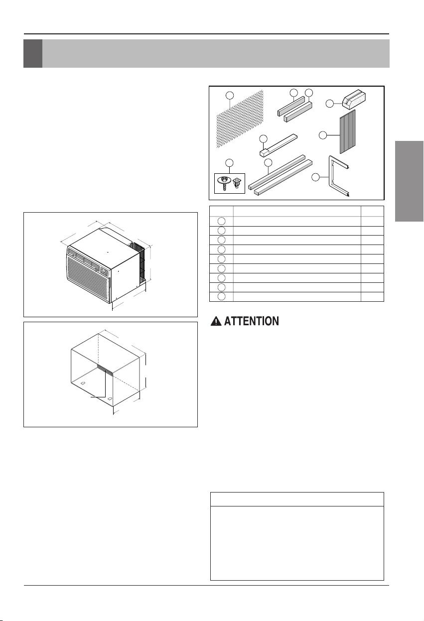
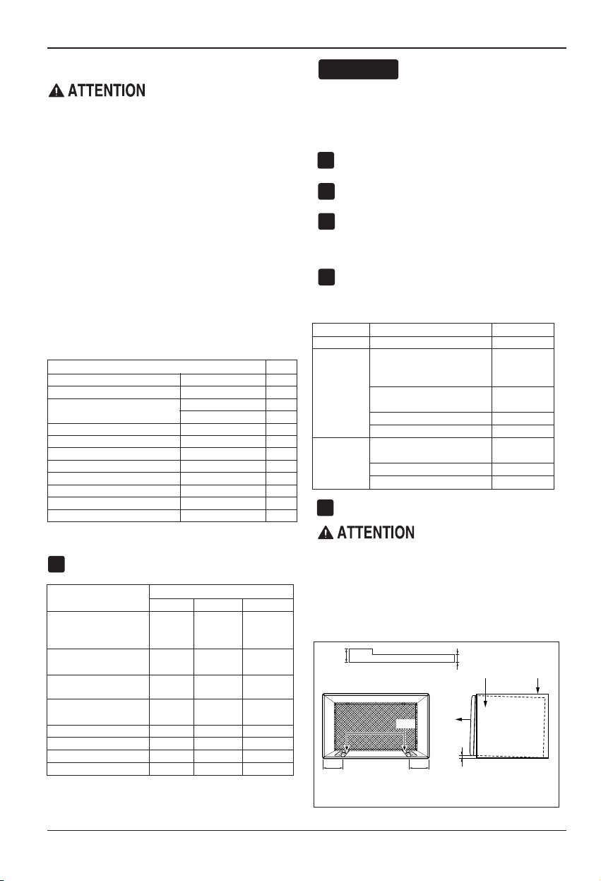
INSTALLATION HARDWARE
14-13/32"
(366 mm)
24"(610 mm)
18-15/32"(468 mm)
20-3/32"
(511 mm)
To avoid risk of personal injury, property
damage, or product damage due to the weight of
this device and sharp edges that may be
exposed:
• Air conditioners covered in this manual pose an
excessive weight hazard. Two or more people are
needed to move and install the unit.
To prevent injury or strain, use proper lifting and
carrying techniques when moving unit.
• Carefully inspect location where air conditioner will
be installed. Be sure it will support the weight of
theunitoveranextendedperiodoftime.
• Handle air conditioner with care. Wear protective
gloves whenever lifting or carrying the unit. AVOID
the sharp metal fins of front and rear coils.
• Make sure air conditioner does not fall during
installation.
REQUIRED TOOLS:
• Tight Fitting gloves
• Standard screwdriver
• Phillips screwdriver
• Pliers
• Sharp knife
• 3/8-inch open end
wrench or adjustable
wrench
• 1/4-inch hex socket
and ratchet
• Tape measure
• Electric drill
• 1/4-inch drill bit
FIG. 1
Air Conditioner
ITEM NAME OF PARTS Q'TY
1 PLASTIC GRILLE 1
2 VERTICAL INSULATION STRIP 1
3 AROUND INSULATION STRIPS 2
4 HORIZONTAL INSULATION STRIP 1
5 SUPPORT BLOCK 2
6 BAFFLE 1
7TRIMFRAME 2
8SHIM 2
9
PLASTIC NUTS AND WASHER SCREWS
4
FIG. 2
HCI Wall Sleeve
25-7/8"
(656 mm)
Aluminum metal grille
16-23/32"
(425 mm)
15-17/32"
(394 mm)
1
8
9
2 4
2 Size options
3
2 Size options
5
6
7
Page 12
12 Room Air Conditioner
Installation
INSTALLATION
• Pick a location which will allow the conditioned air
to blow into the area you want. Good installation
with special attention to the proper position of the
unit will lessen the chance that service will be
needed.
ITEMS IN INSTALLATION HARDWARE
You may not need all par ts in the kit. Discard unused
parts
HOW TO INSTALL
Identify the existing wall sleeve before installing
the unit from the listed below.
All wall sleeves used to mount the new Air
Conditioner must be in sound structural condition
and have a rear grille that securely attaches to
sleeve, or rear flange that serves as a stop for the
Air Conditioner.
Remove old air conditioner from existing wall
sleeve.
Clean the interior of an existing sleeve.
(Do not disturb seals.)
Wall sleeve must be securely fastened in wall
before installing the air conditioner. Use the
nails or screws through sleeve into wall, if
needed. Repaint sleeve if needed.
Prepare the wall sleeve for installation of the
unit. If you plan to use your existing wall sleeve,
and it is not HCI, use procedure B or C below.
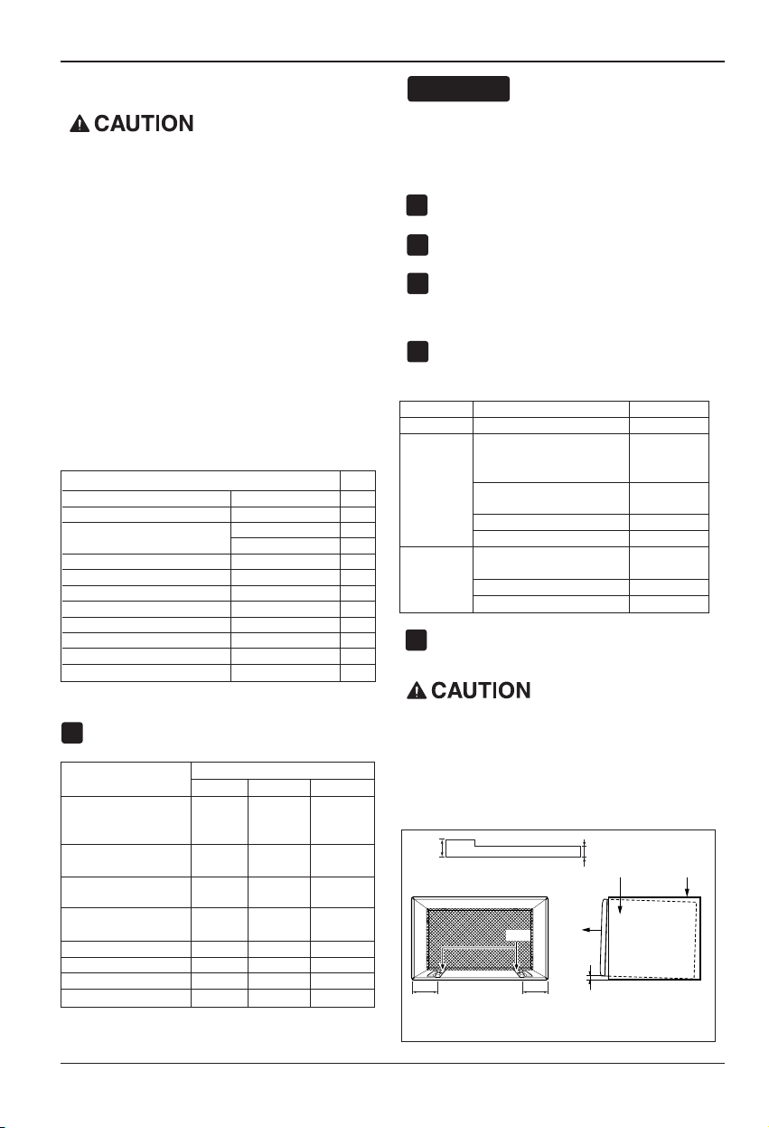
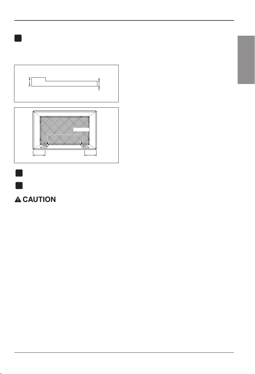
Install new unit into wall sleeve.
When installation is completed, replacement unit
MUST have a rearward slope as shown. To
achieve 1/4" slope, remove the backing from the
11-13/16" shim strips and attach them as shown
below in Fig. 3. Place the higher portion of shim to
the front of the rib on base of wall sleeve.
NOTICE
1
2
3
4
5
6
1/4"
Wall Sleeve
FRONT
UNIT
SHIM PLACEMENT UNIT INSTALLATION
1" high
3
/4" High
Shim
6" 6"
FIG. 3
We strongly recommend the removal of the
old wall sleeve and the installation of a new
HCI Wall Sleeve.
If you decide to keep the existing wall sleeve,
you have to redirect the louvers at the back of
the wall sleeve illustration. The use of pliers is
recommended. If you DO NOT redirect, you
run the risk of poor performance or product
failure. This is not covered under the terms of
the HCI warranty.
ITEM (inches) Qty.
Plastic grille 26
3
/
4
x16
1
/
2
1
Vertical insulation strip 15
9
/
16
x1
3
/
8
x1
3
/
8
1
Around Insulation Strips
67
1
/
8
x1
3
/
8
x
25
/
32
1
59
27
/
32
x1
3
/
8
x1
3
/
8
1
Horizontal Insulation Strip 23
7
/32 x1
3
/
8
x1
3
/16 1
Support Block 1
3
/
4
x1
3
/
8
x4
5
/
16
2
Baffle
14 x
4
1
/
2
x
1
/
8
1
Shim 11
13
/
16
x1x
3
/
4
2
Tr i m F ra m e 2
Washer Screw 4
Nuts(Plastic) 4
Grille Rear 1
Wall Sleeve Dimensions (inches)
Brand
Width Height Depth
White-Westinghouse
25-1/2 15-1/4
16, 17-1/2
Frigidaire
or 22
Carrier (52F series)
General Electric
26 15-5/8 16-7/8
/Hotpoint
Whirlpool 25-7/8 16-1/2
17-1/8
or 23
Fedders/Emerson 27 16-3/4
16-3/4
or 19-3/4
HCI 25-7/8 15-17/32 16-23/32
Emerson/Fedders 26-3/4 15-3/4 15
Carrier (51S Series) 25-3/4 16-7/8 18-5/8
Friedrich 27 16-3/4 16-3/4
Procedure Brand
Depth(inches)
A HCI 16-23/32
White-Westinghouse
Frigidaire Carrier
16, 17-1/2
(52F series)
or 22
B
General Electric
16-7/8
/Hotpoint
Whirlpool 17-1/8 or 23
Carrier (51S series)
18-5/8
Fedders/Emerson
16-3/4
or 19-3/4
C
Emerson/Fedders 15
Friedrich 16-3/4
Page 13
Owner’s Manual 13
ENGLISH
Installation
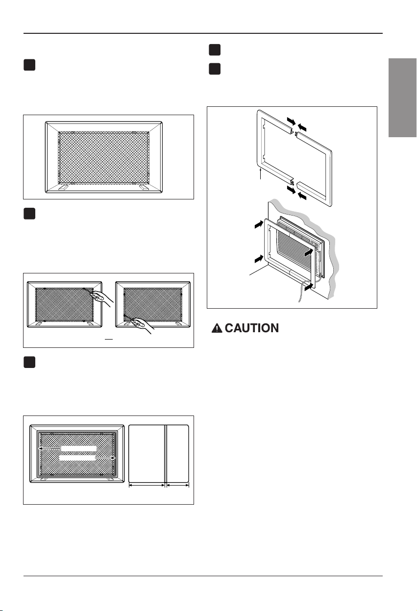
PROCEDURE A
Ifyouareusingthenewsleeve(optionally
supplied with your unit),skip to step 3.
Otherwise, install the plastic grille from the kit.
Cut the plastic grille to 25-1/2" wide and 151/4" high. Place the plastic grille to the inside
of the wall sleeve at the rear flange.
Fasten the 4 washer screws to secure the grille
to the wall sleeve. If you need plastic nuts to
mount plastic grille to the inside of the wall
sleeve, there are plastic nuts in the installation
kit. The nuts are installed from the inside of the
sleeve and are pressing into the square holes
of the rear flanges.
Remove the backing from the Vertical Insulation
strip 15
9
/
16
x1
3
/
8
x1
3
/
8
and attach that to the
inside right of the sleeve as shown below.
Remove the backing from the Around Insulation
strip 67
1
/
8
x1
3
/
8
x
25
/
32
and attach that to the
inside front of the sleeve as shown below.
Install the new unit into the wall sleeve.
To assemble trim, snap the tab of each piece
into the slot of the other piece as shown below.
Slide trim over the front of the air conditioner
until trim is flush with sleeve as shown below.
FIG. 4
Around Insulation
Vertical Insulation
9 1/2"6"
Indoor Outdoor
FIG. 6
or
FIG. 5
1
2
3
4
5
Wall
Trim (2 ea)
FIG. 7
• Air conditioners covered in this manual pose an
excessive weight hazard. Two or more people are
needed to move and install the unit.
To prevent injury or strain, use proper lifting and
carrying techniques when moving unit.
• When handling the air conditioner, be careful to
avoid cuts from sharp metal fins on front and rear
coils.
• Make sure air conditioner does not fall during
removal.
• If unit does not operate after installation check, to
be sure the circuit interrupter has not been tripped.
Refer to the Troubleshooting guide for reset
procedure.
Page 14

14 Room Air Conditioner
Installation
PROCEDURE B
Redirect the louvers at the back of the wall
sleeve to 60° angle as shown in the FIG 8. The
use of pliers is recommended.
If the wall sleeve already has a rear grille, skip
to step 4. If the wall sleeve does not have a rear
grille or louvered panel, install the plastic grille
from the kit. Cut the plastic grille to 25-1/2" wide
and 15-1/4" high. Place the plastic grille to the
inside of the wall sleeve at the rear flange.
Fasten the 4 washer screws to secure the grille
to the wall sleeve. If you need plastic nuts to
mount plastic grille to the inside of the wall
sleeve, there are plastic nuts in the installation
kit. The nuts are installed from the inside of the
sleeve and are pressed into the square holes of
the rear flanges.
Remove the backing from the Vertical Insulation
strip 15
9
/
16
x1
3
/
8
x1
3
/
8
and attach that to the
inside right of the sleeve as shown below.
Remove the backing from the Around Insulation
strip 67
1
/
8
x1
3
/
8
x
25
/
32
and attach that to the
inside front of the sleeve as shown below.
If the depth of your existing wall sleeve is less
than or equal to 18", skip to step 7. Otherwise,
cut the baffles and the support blocks according
to length "A" in the table below.
1
4
2
3
FIG. 9
Around Insulation
Vertical Insulation
9 1/2"6"
Indoor Outdoor
FIG. 11
or
FIG. 10
Rear Louvers
(Top View)
60°
60°
7
3
/
32
"
FIG. 8
Depth"D" of the existing
wall sleeve (inches)
Length "A"
(inches)
Support
Block
Baffle
A
A
3
/4
1-3/4
4
18 D 18-5/
8
18-5/
8
D 19-3/
4
19-3/4 D 22
5
Place the plastic grille
Fasten the screws
FIG. 12
Page 15
Owner’s Manual 15
ENGLISH
Installation
PROCEDURE B
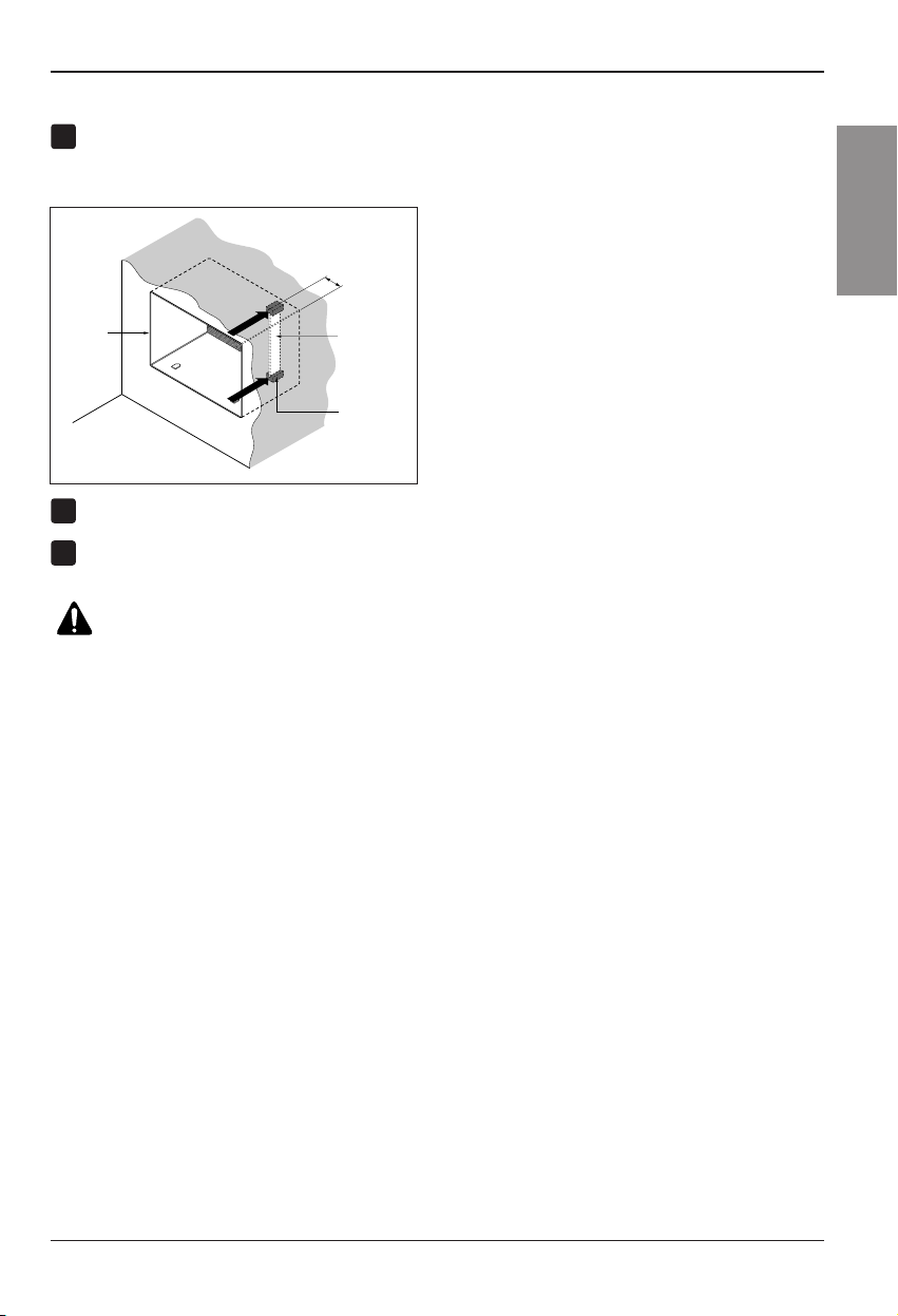
Remove the backing from the support blocks
and attach them to the inside of the wall sleeve
as shown FIG 13. Slide the baffle into slots of
the support blocks.
Install the new unit into the wall sleeve.
Assemble trim as described in Step 5,
Procedure A.
8
Wall
Wall
Sleeve
Baffle
(
7
3
/
32
"
)
Front
Support
Block
FIG. 13
6
7
CAUTION
• Air conditioners covered in this manual pose an
excessive weight hazard. Two or more people are
needed to move and install the unit.
To prevent injury or strain, use proper lifting and
carrying techniques when moving unit.
• When handling the air conditioner, be careful to
avoid cuts from sharp metal fins on front and rear
coils.
• Make sure air conditioner does not fall during
removal.
• If unit does not operate after installation check, to be
sure the circuit interrupter has not been tripped.
Refer to the Troubleshooting guide for reset
procedure.
Page 16
16 Room Air Conditioner
Installation
PROCEDURE C
Redirect the louvers at the back of the wall
sleeve to 60° angle as shown in the FIG 14.
The use of pliers is recommended.
If the wall sleeve already has a rear grille, skip
to step 4. If the wall sleeve does not have a rear
grille or louvered panel, install the plastic grille
from the kit. Cut the plastic grille to 26-1/2" wide
and 15-1/2" high. Place the plastic grille to the
inside of the wall sleeve at the rear flange.
Fasten the 4 washer screws to secure the grille
to the wall sleeve. If you need plastic nuts to
mount plastic grille to the inside of the wall
sleeve, there are plastic nuts in the installation
kit. The nuts are installed from the inside of the
sleeve and are pressed into the square holes of
the rear flanges.
Remove the backing from the Horizontal
Insulation strip 23
7
/
32
x1
3
/
8
x1
3
/
16
and attach
that to the inside right of the sleeve as shown
below. Remove the backing from the Around
Insulation strip 59
27
/
32
x1
3
/
8
x1
3
/
8
and attach
thattotheinsidefrontofthesleeveasshown
below.
If the depth of your existing sleeve is less than
or equal to 18”, skip to step 7. Otherwise, cut
the baffles and the suppor t blocks according to
Length "A" in the table below.
Remove the backing from the support blocks
and attach them to the inside of the wall sleeve
as shown FIG 19. Slide the baffle into slots of
the support blocks
Depth"D" of the existing
wall sleeve (inches)
Length "A"
(inches)
Support
Block
Baffle
A
A
3
/4
1-3/4
4
18 D 18-5/
8
18-5/
8
D 19-3/
4
19-3/4 D 22
Wall
Wall
Sleeve
Baffle
Front
Support
Block
(7
3
/
32
")
FIG. 19
FIG. 18
1
4
2
3
FIG. 15
8 1/2"
Indoor Outdoor
Around Insulation
Horizontal Insulation
FIG. 17
or
FIG. 16
Rear Louvers
(Top View)
60°
7
3
/
32
"
60°
FIG. 14
5
6
Place the plastic grille
Fasten the screws
Page 17
Installation
Owner’s Manual 17
ENGLISH
PROCEDURE C
To achieve rearward slope for unit draining,
remove the backing from the 11
13
/
16
"shim
strips and attach them as shown below in Fig.
21. The higher portion of shim is to be placed
in front of the rib on the base of wall sleeve.
Install the new unit into the wall sleeve
Assemble trim as described in Step 6,
Procedure A.
8
9
7
FIG. 20
1" high
3
/4" High
FIG. 21
• Air conditioners covered in this manual pose an
excessive weight hazard. Two or more people are
needed to move and install the unit.
To prevent injury or strain, use proper lifting and
carrying techniques when moving unit.
• When handling the air conditioner, be careful to avoid
cuts from sharp metal fins on front and rear coils.
• Make sure air conditioner does not fall during
removal.
• If unit does not operate after installation check, to be
sure the circuit interrupter has not been tripped.
Refer to the Troubleshooting guide for reset
procedure.
Shim (2EA)
6" 6"
Page 18
18 Room Air Conditioner
Operating Instructions
Operating Instructions
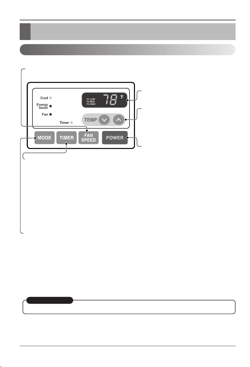
Controls
The controls will look like one of the following.
REMOTE CONTROL SIGNAL
RECEIVER
POWER
MODE
-
Push this button to shift mode of operation from COOL → ENERGY SAVER → FAN.
- COOL:
• Fan runs continually for normal cooling operation.
- ENERGY SAVER:
• The fan stops when the compressor stops cooling. Approximately every 3 minutes the fan will turn on and the unit will
check the room air temperature to determine if cooling is needed.
- FAN:
• Fan-only operation.
TIMER
- SHUT-OFF TIME
• You will usually use shut-off time while you sleep.
• If unit is running, use Timer to set number of hours until shut-off.
• For your sleeping comfort, once Time is set, the Temperature
setting will raise 2°F after 30 min., and once again after another
30 min.
• Push Timer button to advance setting from 1Hour → 2Hours → ...
→ 12Hours maximum.
- START TIME
• If unit is off, use Timer to set number of hours before unit starts.
• Push Timer button to advance setting from 1Hour → 2Hours → ...
→ 12Hours maximum.
TEMPERATURE SETTING
• Use this button to automatically control the
temperature of the room.
The temperature can be set within a range of
60°F to 86°F by increments of 1°F.
• The setting appears in the display.
• To turn the air conditioner ON, push this button.
To turn the air conditioner OFF, push the button
again.
• This button takes priority over any other button.
• When you first turn it on, the unit is in cool
mode, High fan speed, Temperature setting at
72°F.
FAN SPEED
• Every time you push this button, it advances the setting as follows:
{High → Low → Med → High}
AUTO RESTART
When power is restored after an electrical power failure, the unit will begin to run at its last setting.
Page 19
Owner’s Manual 19
ENGLISH
Operating Instructions
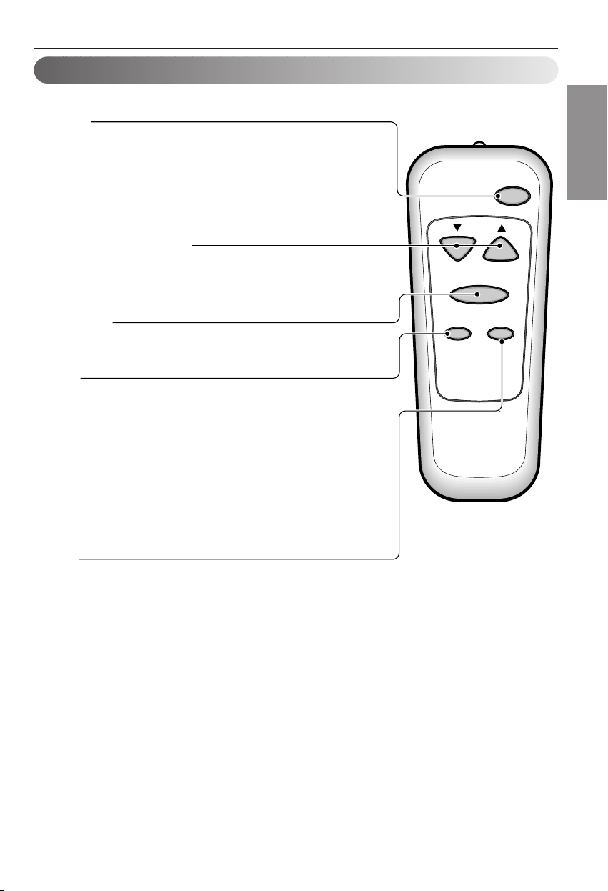
Remote control
The remote control and control panel will look like one of the following pictures.
Powe r
Temp
Fan Speed
Timer Mode
POWER
• To turn the air conditioner ON, push this button.
To turn the air conditioner OFF, push the button again.
• This button takes priority over any other button.
• When you first turn it on, the unit is in cool mode, High fan speed,
Temperature setting at 72°F.
• Auto Restart
In the event at a power failure, the unit will run at the previous setting once
power returns.
TEMPERATURE SETTING
• Use this button to automatically control the temperature of the room.
The temperature can be set within a range of 60°F to 86°F by
increments of 1°F.
• The setting appears in the display.
FAN SPEED
• Every time you push this button it advances the setting as follows:
(High → Low → Med → High)
TIMER
- SHUT-OFF TIME
• You will usually use shut-off time while you sleep.
• If unit is running, use Timer to set number of hours until shut-off.
• For your sleeping comfort, once Time is set, the Temperature setting will
raise 2°F after 30 min, and once again after another 30 min.
• Push Timer button to advance setting from 1Hour
→
2Hours → ...
→
12Hours maximum.
- START TIME
• If unit is off, use Timer to set of hours before unit starts.
• Push Timer button to advance setting from 1Hour
→
2Hours → ...
→
12Hours maximum.
MODE
- Push this button to shift mode of operation from COOL → ENERGY SAVER → FAN.
- COOL:
• Fan runs continually for normal cooling operation.
- ENERGY SAVER:
• The fan stops when the compressor stops cooling. Approximately every 3 minutes the fan will turn on
and the unit will check the room air temperature to determine if cooling is needed.
- FAN:
• Fan-only operation.
Page 20
20 Room Air Conditioner
Operating Instructions
PULL OPEN / PUSH CLOSE
Ventilation
Air Direction
The ventilation lever is located in the right of the air discharge.
The ventilation lever must be in the CLOSE position in order to
maintain the best cooling conditions.
When fresh air is necessary in the room, set the ventilation lever to
the OPEN position.
The damper is opened and room air is exhausted outside.
The direction of air can be controlled wherever you want by adjusting the horizontal louver and the vertical louver.
• HORIZONTAL AIR-DIRECTION
CONTROL
The horizontal air direction is adjusted by moving
vertical louver.
The lever of vertical louver is located in the right and
left side of the air discharge.
• VERTICAL AIR-DIRECTION CONTROL
The vertical air direction is adjusted by moving the
horizontal louver.
How to insert Batteries
1. Remove the cover from the back of the remote
controller.
2. Insert two batteries.
• Be sure that the (+) and (-) directions are
correct.
• Be sure that both batteries are new.
3. Re-attach the cover.
• Do not use rechargeable batteries.
Such batteries differ from standard
dry cells in shape, dimensions, and
performance.
• Remove the batteries from the
remote controller if the air
conditioner is not going to be used
for an extended length of time.
Page 21
Owner’s Manual 21
ENGLISH
Maintenance and Service
Maintenance and Service
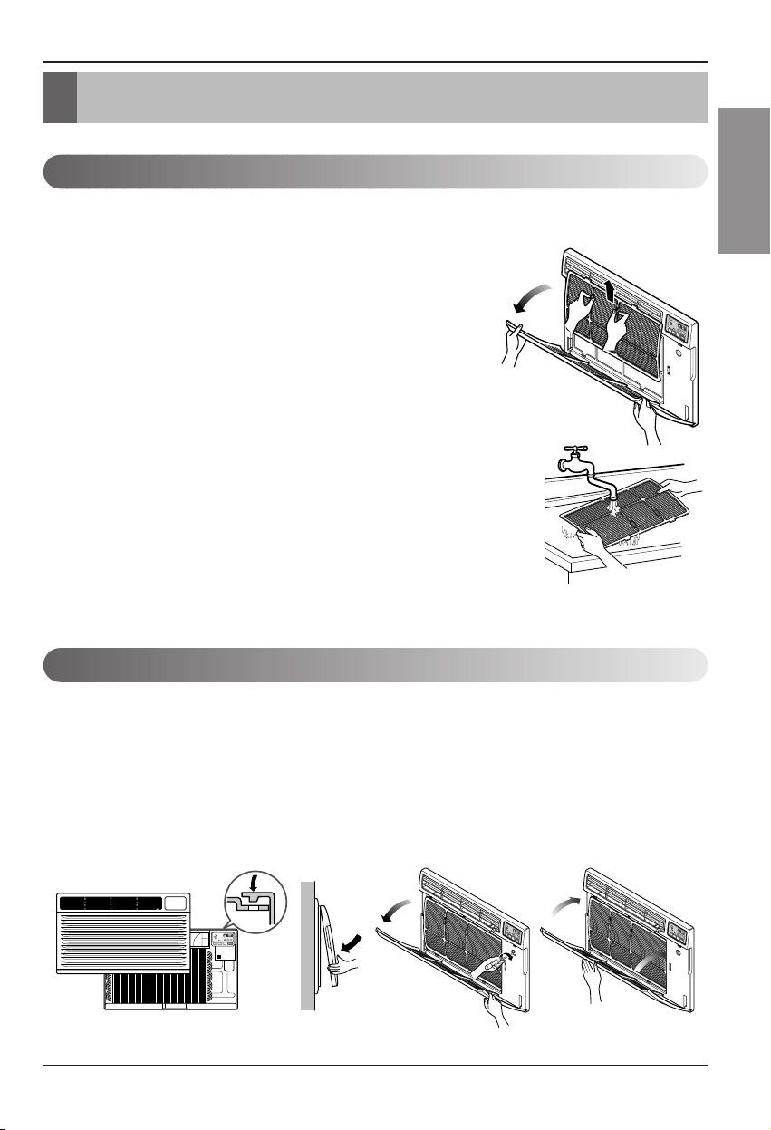
Air Filter Cleaning
How to Attach Front Grille to Cabinet
TURN THE AIR CONDITIONER OFF AND REMOVE THE PLUG FROM THE POWER OUTLET.
The air filter should be checked at least twice a month to see if cleaning is necessary.
Trapped particles in the filter will build up and block the airflow.This reduces the cooling
capacity and also causes an accumulation of frost on the cooling coils.
If the filter becomes turn or damaged you should replace
immediately. Replacement filters are available from your
salesperson, dealer, and the authorized customer service
centers.
1. Open the inlet grille downward by pulling out the top of the
inlet grille.
2. Remove the air filter from the front grille assembly by
pulling the air filter up slightly.
3. Wash the filter using lukewarm water below 40°C (104°F).
4. Gently shake the excess water from the filter completely.
Replace the filter.
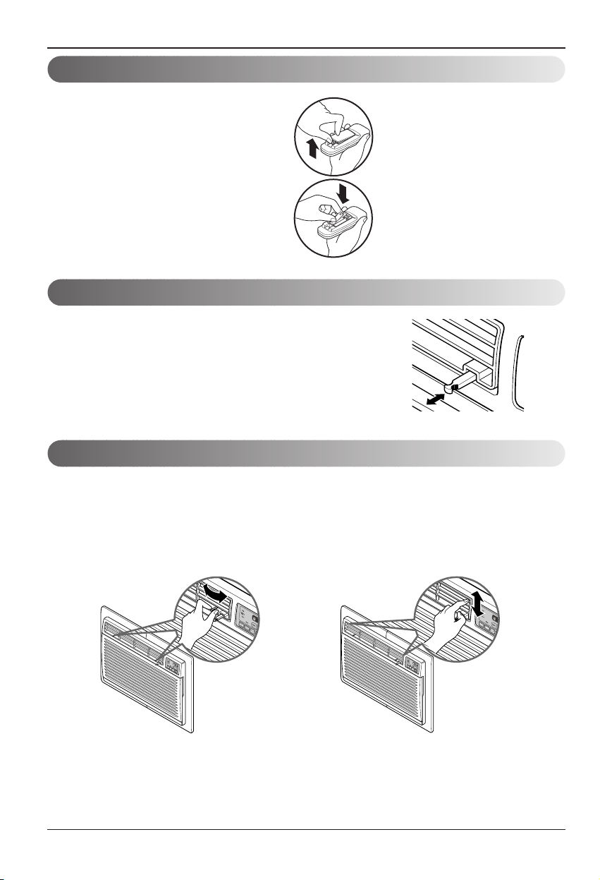
The front grille can be removed for cleaning or to check the model and serial numbers.
For your safety, you should attach the front grille as the following procedures.
1. Pull down front grille from the cabinet top.
2. Push front grille’s tips toward the cabinet in
order to insert front grille’s tabs into the
cabinet.
3. Open the inlet grille.
4. Tighten the screw through the front grille into
the plate of control box.
5. Close inlet grille.
Page 22

22 Room Air Conditioner
Maintenance and Service
Common Problems and Solutions
Troubleshooting
Normal Operation
Troubleshooting Tips Save time and money!
Review the chart below first and you may not need to call for service.
• You may hear a pinging noise caused by water being picked up and thrown against the condenser on rainy
days or when the humidity is high. This design feature helps remove moisture and improve efficiency.
• You may hear the thermostat click when the compressor cycles on and off.
• Water will collect in the base pan during high humidity or on rainy days.The water may overflow and drip from
the outdoor side of the unit.
• The fan may run even when the compressor does not.
Problem Possible Causes What To Do
■ The air conditioner is
unplugged.
■ The fuse is blown/circuit
breaker is tripped.
■ Power failure.
■ The current interrupter
device is tripped.
■ Airflow is restricted.
■ TEMP Control set too
higher number.
■ The air filter is dirty.
■ The room may have been
hot.
■ Cold air is escaping.
■ Cooling coils have iced up.
■ Ice blocks the air flow and
stops the air conditioner
from cooling the room.
• Make sure the air conditioner plug is pushed
completely into the outlet.
• Check the house fuse/circuit breaker box and replace
the fuse or reset the breaker.
• If power failure occurs, turn the mode control to OFF.
When power is restored, wait 3 minutes to restart the
air conditioner to prevent tripping of the compressor
overload.
• Press the RESET button located on the power cord
plug. If the RESET button will not stay engaged,
discontinue use of the air conditioner and contact a
qualified service technician.
• Make sure there are no curtains, blinds, or furniture
blocking the front of the air conditioner.
• Set the TEMP control to a lower number.
• Clean the filter at least every 2 weeks.
See the operating instructions section.
• When the air conditioner is first turned on,
you need to allow time for the room to cool down.
• Check for open furnace floor registers
and cold air returns.
• Set the air conditioner's vent to the closed position.
• See Air Conditioner Freezing Up below.
• Set the mode control at High Fan or High Cool with
the high temperature.
Air conditioner
does not start
Air conditioner
does not cool as it
should
Air conditioner
freezing up
Page 23

Owner’s Manual 23
ENGLISH
For Models Installed Outside North America- For room air conditioners purchased for use outside North
America the manufacturer does not extend any warranty implied or expressed. Consult your dealer for any
warranty terms extended by the importer in your country.
If you have read the Installation and Operating booklet completely and feel you need service call
1-877-755-7932
or you may write:
Heat Controller Inc.
1900 Wellworth Ave. Jackson, MI 49203
ProofofPurchaseDate
It is the responsibility of the consumer to establish the original purchase date for warranty purposes. We
recommend a bill of sale, cancelled check or some other appropriate payment record be kept for that purpose.
If you have additional questions you may call 1-517- 787-2100
Or E-Mail customerservice@heatcontroller.com or techservice@heatcontroller.com
Call (517) 787-2100 for obtaining service parts beyond your warranty period.
Page 24

24 Room Air Conditioner
Memo
Page 25
Séries
murales
Information importante
HEAT CONTROLLER, INC.
• Veuillez lire ce manuel soigneusement et en entier avant la mise en service de l'appareil.
• Contactez le service technique autorisé pour l'installation, l'entretien ou pour une éventuelle
réparation de l'unité.
• L'appareil ne doit pas être actionné par des enfants ou par des personnes infirmes sans
surveillance.
• Veillez toujours à surveiller les enfants pour éviter qu'ils jouent avec l'appareil.
Modeles: BG-81A
BG-101A
BG-123A
Page 26

2 Climatiseur de pièce
Manuel du propriétaire du climatiseur de pièce type fenêtre
TABLE DES MATIÈRES
Mesures de sécurité........................3
Avant l'utilisation.............................7
Introduction .....................................8
Sécurité électrique .........................9
Guide d'installation ......................11
Instructions d'utilisation ..............18
Entretien et réparations................21
POUR VOS ARCHIVES
Écrivez les numéros de modèle et de série ici :
Modèle #
Série #
Vous les trouverez sur la plaque signalétique située sur le
côté de chaque unité.
Nom du distributeur
Date d’achat
■ Agrafez votre reçu à cette page au cas où vous en
auriez besoin pour démontrer la date d'achat du produit
ou pour avoir droit à la garantie.
LISEZ CE MANUEL
Vous trouverez à l’intérieur de ce manuel beaucoup de
conseils utiles sur la façon d’utiliser et d’entretenir
correctement votre climatiseur. Quelques petites mesures
préventives vous permettront d’épargner beaucoup de
temps et d’argent pendant la durée de vie de votre
climatiseur.
Vous trouverez beaucoup de réponses aux problèmes les
plus fréquents dans le tableau du guide de dépannage. Si
vous passez en revue notre Guide de Dépannage d'abord,
il se peut que vous n’ayez pas du tout besoin d’appeler le
Service Après-Vente.
PRÉCAUTION
• Contactez le service technique agréé pour la réparation
ou l'entretien de cette unité.
• Contactez un technicien autorisé pour l'installation de
cette unité.
• Ce climatiseur ne doit pas être actionné par des petits
enfants ou par des personnes infirmes sans surveillance.
• Veillez toujours à surveiller les petits enfants pour éviter
qu’ils jouent avec l'appareil.
• Si le cordon d’alimentation doit être remplacé, ce travail
ne doit être accompli que par du personnel autorisé
utilisant uniquement des pièces de rechange authentiques.
• Conformément au Code électrique national, l’installation
ne doit être effectuée que par du personnel qualifié et
autorisé.
Page 27

FRANÇAIS
Manuel de l'utilisateur 3
Mesures de sécurité
Mesures de sécurité
Les instructions ci-après doivent être observées dans le but de prévenir tout risque de
dommages corporels ou matériels.
■ L'utilisation non conforme, résultant de la négligence des instructions, est susceptible de
provoquer des dommages corporels ou matériels dont la gravité est signalée par les
indications suivantes.
■ Les significations des symboles utilisés dans ce manuel sont indiquées ci-dessous.
Ce symbole indique un risque de blessure grave, voire mortelle.
Ce symbole indique un risque de blessure ou des dommages
matériels seulement.
AVERTISSEMENT
Veillez à ne pas faire cela.
Veillez à suivre les instructions de ce manuel.
■ Installation
N'utilisez pas un cordon
d’alimentation, une fiche
d’alimentation ou une prise
de courant endommagés.
• N'utilisez pas un cordon
d’alimentation, une fiche
d’alimentation ou une prise de
courant endommagés.
Mettez toujours à terre le
produit.
• Ne pas le faire peut provoquer
un incendie ou un choc
électrique.
Ne modifiez ni ne rallongez
le cordon d’alimentation.
•Celaprovoqueraunchoc
électrique ou un incendie, dû
au dégagement de chaleur.
Ne démontez ni ne réparez
vous-même l’appareil.
• Cela peut provoquer un
mauvais fonctionnement ou
un choc électrique.
Soyez prudent pendant le
déballage et l’installation.
• Les bords aiguisés peuvent
provoquer des blessures.
N’utilisez pas de gaz
inflammable ni de
combustibles tels qu’essence,
benzène, diluant, etc. prèsdu
cordon d’alimentation.
• Cela peut provoquer une
explosion ou un incendie.
Gasolin
AVERTISSEMENT
ATTENTION
Page 28

4 Climatiseur de pièce
Mesures de sécurité
■ Fonctionnement
Ne placez pas le cordon
d’alimentation prèsd’un
dispositif de chauffage.
• Cela peut provoquer un
incendie ou un choc
électrique.
Ne permettez pas que de
l’eau entre en contact avec
les pièces électriques.
• Cela provoquera le mauvais
fonctionnement de l’appareil
ou un choc électrique.
Utilisez un tissu doux pour
nettoyer l’appareil. N'employez
ni de cire, ni de diluant ni de
détergent fort.
• Vous risquez de détériorer
l’aspect de l’appareil, changer
sa couleur ou provoquer des
défauts sur sa surface.
Wax
Thinner
Aérez bien lors de
l’utilisation de l’appareil
simultanément avec un
poêle, etc.
• Il peut y avoir un manque
d'oxygène.
Coupez l’alimentation et
fermez l’interrupteur avant
de nettoyer l’unité.
• Puisque le ventilateur tourne
à haute vitesse lors du
fonctionnement, cela peut
provoquer des
blessures.
Fermez l’interrupteur principal
lorsque le climatiseur ne sera
pas utilisé pendant une longue
période.
• Évitez un démarrage
accidentel et la possibilité de
blessures.
Débranchez l’unité si vous
constatez la présence de
bruits étranges, d’odeurs ou
de fumée provenant de
l’appareil.
• Autrement, vous risquez de
provoquer un incendie ou un
choc électrique.
N’ouvrez pas l’ouverture
d’aspiration du produit lors
du fonctionnement.
• Autrement, vous risquez de
provoquer un choc électrique
ou un mauvais
fonctionnement.
Si de l’eau entre en contact avec
le produit, fermez l’interrupteur
de l’unité principale du produit.
Débranchez l’appareil et
contactez le service après-vente.
Ne placez pas d’objets
lourds sur le cordon
d’alimentation et veillez à ce
que le cordon ne reste pas
pressé.
• Vous risquez de provoquer un
incendie ou un choc
électrique.
Ne partagez pas la prise
avec d’autres appareils.
• Cela peut provoquer un choc
électrique ou un incendie, dû
au dégagement de chaleur.
Le cas échéant, débranchez la
fiche d’alimentation, en la
prenant par la tête, et ne la
touchez pas avec les mains
mouillées.
• Autrement, vous risquez de
provoquer un incendie ou un
choc électrique.
Page 29

FRANÇAIS
Manuel de l'utilisateur 5
Mesures de sécurité
ATTENTION
■ Installation
Ne démarrez ni n’arrêtez
l’unité en branchant ou
débranchant le cordon
d’alimentation.
• Cela provoquera un choc
électrique ou un incendie, dû
au dégagement de chaleur.
N’endommagez pas le
cordon d’alimentation et
n’utilisez pas un cordon
d’alimentation quelconque.
•Celaprovoqueraunchoc
électrique ou un incendie.
Ne faites pas fonctionner
l’appareil avec les mains
mouillées ou dans un
environnement humide.
•Celaprovoqueraunchoc
électrique.
Débranchez la fiche
d’alimentation, en la prenant
par la tête.
• Cela provoquera un choc
électrique et des dommages.
S’il y a une fuite de gaz, ouvrez
la fenêtre et aérez avant de
redémarrer l’unité.
• Autrement, vous risquez de
provoquer une explosion et un
incendie.
Ne touchez jamais les pièces
métalliquesdel’unité lorsque
vous retirez le filtre.
• Elles sont aiguisées et peuvent
provoquer des blessures.
Installez le produit de sorte que vos voisins
ne soient pas dérangés par le bruit ou par
le vent chaud venant de l'unité extérieure.
• Autrement, vous risquez de susciter des
querelles avec les voisins.
Maintenez le niveau lors de l’installation du
produit.
• Autrement, vous risquez de provoquer des
vibrations ou une fuite d'eau.
Page 30

6 Climatiseur de pièce
Mesures de sécurité
■ Fonctionnement
Soyez prudent pendant
l’installation.
• Les bords aiguisés peuvent
provoquer des blessures.
Évitez le refroidissement
excessif et aérez parfois.
• Autrement, vous risquez de nuire
à votre santé.
N’introduisez pas les mains ou
desbarresdansl'entréeoula
sortie d’air lors du
fonctionnement.
• Autrement, vous risquez de vous
blesser.
N’exposez pas les animaux
domestiques ou les plantes
d’intérieur au flux d’air direct.
• Vous risquez de nuire à l’animal
ouàlaplante.
Ne bloquez pas l'entréeoula
sortie du flux d’air.
• Vous risquez de causer le
mauvais fonctionnement du
produit.
Utilisez un tissu doux pour
nettoyer l’appareil. N'employez
ni de cire, ni de diluant ni de
détergent fort.
• Vous risquez de détériorer
l’aspect de l’appareil, changer sa
couleur ou provoquer des défauts
sur sa surface.
Ne montez sur l’unité
intérieure/extérieure ni n’y
placez aucun objet.
• Autrement, vous risquez de
vous blesser en tombant de
l’appareil.
Installez toujours le filtre de
façon correcte. Nettoyez-le
toutes les deux semaines.
• Le fonctionnement sans filtres
provoquera des défauts dans
l’appareil.
Ne buvez pas l'eau
s'écoulant du climatiseur.
• Elle contient des polluants qui
nuiront à votre santé.
Page 31

Avant l'utilisation
Manuel de l'utilisateur 7
FRANÇAIS
1. Contactez un spécialiste en installations pour l'installation.
2. Branchez correctement la prise d'alimentation.
3. Utilisez un circuit dédié.
4. N'utilisez pas de rallonges.
5. Ne mettez pas en marche ou éteignez cet appareil en branchant/débranchant le cordon
d'alimentation.
6. Si le cordon ou la fiche est endommagé, remplacez-le seulement par une pièce de rechange
autorisée.
1. S'exposer directement sous le flux d'air pour une longue période de temps pourrait entraîner des
risques pour la santé.
N'exposez pas directement les occupants, les animaux ou les plantes au flux d'air pour de
longues périodes de temps.
2. Afin d'éviter de possibles déficiences d'oxygène, aérez la pièce lorsque vous utilisez cette unité
simultanément avec des poêles ou d'autres dispositifs de chauffage.
3. N'utilisez pas ce climatiseur pour des objectifs spéciaux non spécifiés dans ce manuel (p.ex. pour
préserver des dispositifs de précision, des aliments, des animaux, des plantes ou des objets
d'art). Un tel usage pourrait endommager les composants de l'unité.
1. Ne touchez pas aux composants métalliques de l'unité lors de l'enlèvement du filtre. Vous
pourriez vous blesser en manipulant des bords métalliques affilés.
2. N'utilisez pas de l'eau pour nettoyer l'intérieur du climatiseur. Le contact avec de l'eau détruit
l'isolement, entraînant de possibles chocs électriques.
3. Lors du nettoyage de l'unité, assurez-vous d'abord que
l'interrupteur et le disjoncteur sont sur la position Arrêt (OFF). Le ventilateur tourne à une vitesse
très forte pendant que l'unité est en marche. Vous pourriez vous blesser si l'unité est
accidentellement mise en marche alors que vous nettoyez les parties intérieures de l'unité-
Pour réparation et maintenance, contactez le service technique agrée de votre revendeur.
Avant l'utilisation
Préparation pour la mise en service
Utilisation
Nettoyage et entretien
Service technique
Page 32

8 Climatiseur de pièce
Introduction
Ce symbole indique un risque de choc électrique.
Ce symbole indique des risques qui pourraient endommager le
climatiseur.
Ce symbole indique des remarques particulières
REMARQUE
Cet appareil doit être installé conformément aux standards nationaux sur le câblage.
Introduction
Symboles Utilisés dans ce Manuel
Caractéristiques
LE MANCHON ET LA GRILLE ARRIÈRE
(fournis en option avec l’unité)
ENSEMBLE DU MANCHON
(Grille arrière en aluminium y comprise)
GRILLE D’ENTRÉE D’AIR
DÉFLECTEUR D’AIR VERTICAL
FILTRE À AIR
(Entrée d’air)
DÉFLECTEUR D’AIR HORIZONTAL
(Volet horizontal)
(Volet vertical)
COMMANDE DE L’ORIFICE DE VENTILATION
GRILLE ARRIÈRE
(Grille arrière en aluminium)
L’UNITÉ
SORTIE D’AIR
BOÎTIER
GRILLE AVANT
Page 33

Sécurité électrique
Manuel de l'utilisateur 9
FRANÇAIS
Sécuritéélectrique
Données électriques
Laformepeutvarierenfonctiondumodèle.
REMARQUE
N'UTILISEZ PAS DE RALLONGE pour des unités
à 230, 208 et 230/208 volts.
Tout le câblage doit être effectué conformément
aux réglementations et aux codes électriques
locaux.
Une installation électrique en aluminium peut poser
des problèmes particuliers. Consultez un
électricien qualifié.
REMARQUE
Ne jamais appuyer sur le bouton TEST lorsque
l’appareil est en fonctionnement. Autrement, la prise
de courant pourrait être endommagée.
L’appareil contient des substances chimiques, dont
du plomb, qui est reconnu par l’Etat de Californie
comme pouvant provoquer des cancers, des
anomalies congénitales ou des troubles de la
fertilité.
Lavez-vous les mains après utilisation.
Ne pas retirer, modifier ni immerger la prise de
courant.
Si l’appareil ne fonctionne pas normalement, le
problème doit être réparé avant toute nouvelle
utilisation.
Les conducteurs présents à l’intérieur du câble sont
entourésd’écrans de protection qui contrôlent les
fuites de courant.
Ces écrans de protection ne sont pas mis à la terre.
Vérifiez de temps en temps que le câble ne soit pas
endommagé. Ne pas utiliser l’appareil si les écrans
de protection sont visibles.
Evitez tout risque de décharge électrique. Cet
appareil n’a pas été conçu pour être révisé par
l’utilisateur car vous ne devez pas ouvrir le boîtier
inviolable. Si la partie étanche de l’appareil a été
forcée, la garantie est annuléeetladéclaration de
mauvais fonctionnement ne sera pas prise en
compte. L’appareil n’apasété conçupourêtre utilisé
comme un interrupteur électrique.
115V~ 230V~
Utilisez une prise murale Alimentation
Prise trifilaire standard de 125 V,
avec mise à la terre, classée 15 A,
pour c.a. de 125 V.
Prise trifilaire standard de 250 V,
avec mise à la terre, classée 15 A,
pour c.a. de 250 V.
Prise trifilaire standard de 250 V,
avec mise à la terre, classée 20 A,
pour c.a. de 250 V.
Utilisez un fusible à
action différée ou un
coupe-circuit de
15 ampères.
Utilisez un fusible à
action différée ou un
coupe-circuit de
20 ampères.
Le cordon d'alimentation peut inclure un
dispositif de coupure. Un bouton Test et un
bouton Reset (rétablir) sont fournis dans le
boîtier de la fiche. Ce dispositif doit être
périodiquement testé en appuyant d'abord
sur le bouton TEST et ensuite sur le bouton
RESET. Si le bouton TEST ne déclenche
pas ou que le bouton RESET ne reste pas
activé, veuillez suspendre l'utilisation du
climatiseur et contacter un technicien
Page 34

10 Climatiseur de pièce
Sécurité électrique
IMPORTANT
(VEUILLEZ LIRE ATTENTIVEMENT CETTE
SECTION.)
CET APPAREIL DOIT ÊTRE CORRECTEMENT
RELIÉ À LA TERRE, AFIN DE PRÉSERVER LA
SÉCURITÉ PERSONNELLE DE L'UTILISATEUR
Le cordon d'alimentation de cet appareil est muni
d'une fiche tripolaire pour mise à la terre. Pour réduire
au minimum le risque de choc électrique, utilisez cette
fiche sur une prise murale standard à trois encoches.
Le client doit demander à un électricien qualifié de
vérifier la prise murale ainsi que le circuit afin de
confirmer que la prise murale est correctement reliée
à la terre.
NE COUPEZ NI N'ENLEVEZ LA BROCHE DE MISE
A LA TERRE DE LA FICHE
A. SITUATIONS PRÉSENTÉES LORSQUE L'APPAREIL
EST DÉBRANCHÉ DE TEMPS EN TEMPS :
En raison des risques potentiels pour la sécurité,nous
décourageons vivement l'utilisation d'un adaptateur.
Cependant, si vous voulez utiliser un adaptateur, il est
possible d'effectuer une CONNEXION TEMPORAIRE.
Utilisez un adaptateur certifié UL, commercialisé dans
la plupart des magasins de matériel électrique.
La grande encoche de l'adaptateur doit être alignée
avec la grande encoche de la prise murale afin
d'assurer un branchement respectant la polarité.
:
Raccorder la borne de mise à laterredel'adaptateur
à lavisducouvercledelaprisemuralen'assurepas
la mise à la terre, à moinsquelavisducouverclesoit
métallique et non isolée et que la prise murale soit
mise à la terre par l'intermédiaire de l'installation
électrique. Le client doit demander à un électricien
qualifié de vérifier le circuit afin de confirmer que la
prise murale est correctement reliée à la terre.
Pour débrancher le cordon d'alimentation de
l'adaptateur, prenez chacun d'eux avec une main.
Autrement, la borne de terre de l'adaptateur pourrait
en résulter endommagée. N'UTILISEZ PAS cet
appareil avec un adaptateur cassé.
B. SITUATIONS PRÉSENTÉES LORSQUE
L'APPAREIL EST FRÉQUEMMENT DÉBRANCHÉ.
N'utilisez pas d'adaptateur dans ces situations.
Débrancher le cordon d'alimentation fréquemment
peut éventuellement endommager la borne de terre.
Dans ce cas, la prise murale doit être remplacéepar
une prise à trois encoches reliée à la terre.
UTILISATION DE RALLONGES
En raison des risques potentiels pour la sécurité,nous
décourageons vivement l'utilisation d'une rallonge.
Cependant, si vous voulez utiliser une rallonge, utilisez
une rallonge trifilaire (pour mise à la terre) certifiéeUL
et CSA, classée15A,pour125V.
Sécurité électrique
Page 35
Manuel de l'utilisateur 11
FRANÇAIS
Installation
Installation
Enlevez les matériaux d’emballage du manchon mural et
la bande du climatiseur.
CONDITIONS D’INSTALLATION
Si vous utilisez un manchon mural déjà existant,
mesurez-en les dimensions.
Pour un meilleur rendement, installez ce climatiseur selon
les instructions d’installation du présent manuel. Le
manchon mural utilisé pour monter ce nouveau climatiseur
doit êtreenbonétat au niveau de sa structure et être
pourvu d’une grille arrière permettant d’attacher
solidement le nouvel appareil. (FIG. 1)
Le manchon de HCI (fourni en option avec l’unité),
vous assure une meilleure performance pour votre
climatiseur. (FIG. 2)
SERVICE ÉLECTRIQUE
Vérifiez votre service électrique disponible. L’alimentation
électrique doit être identique à celle qui est marquéesurla
plaque signalétique de l’unité (sur le côté gauche du
boîtier).
Tous les modèles sont équipésd’une fiche tripolaire
assurant un service approprié et une mise à la terre sûre.
Ne changez la prise de courant en aucun cas. N’utilisez pas
d'adaptateur. Si votre prise murale actuelle n’assortit pas la
fiche, contactez un électricien qualifié pour faire les
modifications nécessaires. CONSERVEZ LA BOÎTE EN
CARTON pour le stockage et le présent MANUEL DU
PROPRIÉTAIRE pour une référence ultérieure. La boîte en
carton est la meilleure manière de stocker l'appareil
pendant l’hiver ou lorsqu’il n’est pas utilisé.
INSTALLATION DU MATÉRIEL
14-13/32"
(366 mm)
24"(610 mm)
18-15/32"(468 mm)
20-3/32"
(511 mm)
Évitez tout risque de blessures, dégâts matériels ou
dommages à l’unité dus au poids de l’appareil ainsi qu’aux
bords aiguisés pouvant être exposés.
• Les climatiseurs compris dans le présent manuel entraînent
un danger majeur en raison de leur poids. Deux personnes ou
plus sont nécessaires pour déplacer et installer cette unité.
Pour éviter des blessures ou des efforts inutiles lors du
déplacement de l’unité, appliquez des techniques de levage et
de déplacement appropriées.
• Examinez soigneusement l’emplacement où le climatiseur
sera installé. Assurez-vous qu’il supportera le poids de l’unité
pendant une longue période.
• Manipulez le climatiseur avec soin. Utilisez des gants de
protection lors du levage et du déplacement de l’unité.
ÉVITEZ les bords métalliques aiguisés des serpentines avant
et arrière.
• Faites très attention à ce que l’appareil ne tombe pas pendant
l’installation.
OUTILS NÉCESSAIRES :
• Gants de protection
serrés
• Tournevis standard
• Tournevis de type
Phillips
• Pinces
• Couteau tranchant
• Cléàfourchede3/8
pouces ou cléàmolette
• Cléàsix pans à rochet
avec douille de 1/4
pouces
• Centimètre
• Perceuse électrique
• Mèche de 1/4 pouces
FIG. 1
Climatiseur
ARTICLE
NOM DES PIÈCES Q’TÉ
1 GRILLE EN PLASTIQUE 1
2 JOINT D'ISOLATION VERTICAL 1
3 JOINTS D'ISOLATION CIRCULAIRES 2
4 JOINT D’ISOLATION HORIZONTAL 1
5 BLOCS DE SOUTIEN 2
6DÉFLECTEUR 1
7 CADRE DE FINITION 2
8CALE 2
9
ÉCROUS EN PLASTIQUE ET VIS À RONDELLE
4
FIG. 2
HCI Wall Sleeve
1
8
9
2 4
5
2 options de taille
3
2 options de taille
6
7
25-7/8"
(656 mm)
15-17/32"
(394 mm)
Grille métallique
en aluminium
16-23/32"
(425 mm)
Page 36
12 Climatiseur de pièce
Installation
INSTALLATION
• Choisissez un emplacement qui permette le
climatiseur de souffler vers la direction souhaitée.
L’installation appropriée, en faisant particulièrement
attention à la correcte mise en place de l'unité,
diminuera les chances d'avoir à appeler le service
technique.
COMPOSITION DU MATÉRIEL D’INSTALLATION
Il se peut que vous n’ayez pas besoin de toutes les
pièces du kit. Écartez les pièces inutiles.
PROCÉDURE D’INSTALLATION
Identifiez le manchon mural déjà existant avant
d’installer les pièces de l’unité ci-dessus.
Le manchon mural utilisé pour monter ce nouveau
climatiseur doit êtreenbonétat au niveau de sa
structure et être pourvu d’une grille arrière s’attachant
solidement au manchon, ou bien d’une bride arrière
servant de taquet au climatiseur.
Enlevez le vieux climatiseur du manchon mural
existant.
Nettoyez l’intérieur du manchon existant. (Ne
dérangez pas les joints)
Le manchon mural doit être solidement attaché au
mur avant d’installer le climatiseur. Au besoin, fixez le
manchon au mur à l’aide de clous ou des vis.
Repeignez le manchon si nécessaire.
Préparez le manchon mural pour l’installation de
l’unité. Si vous envisagez d’utiliser un manchon déjà
existant, et que ce n’est pas un manchon HCI, suivez
la procédure B ou C ci-dessous.
Installez la nouvelle unité dans le manchon mural.
Une fois l’installation complétée, veillez à ce que la
nouvelle unité AIT une inclinaison en arrière, tel que
montré. Pour obtenir une inclinaison de 1/4”, ôtez le film
protecteur des joints des cales de 11-13/16" et fixez-les
tel que montré dans la figure 3. Placez la partie la plus
élevéedelacaleà l’avant de la nervure du manchon
mural.
REMARQUE
1
2
3
4
5
6
1/4"
Manchon Mural
PARTIE
AVANT
UNITÉ
PLACEMENT DE LA CALE INSTALLATION DE L’UNITÉ
1" de
hauteur
3
/4" de hauteur
Cale
6" 6"
FIG. 3
Il est fort recommandé de remplacer le vieux
manchon mural par un nouveau manchon
mural HCI.
Or, si vous décidez de conserver le manchon déjà
existant, vous devrez réorienter les volets sur la
partie postérieure du manchon mural. Il est
recommandé de le faire à l’aide de pinces. Si vous
NE les réorientez PAS, vous risquez de provoquer
un rendement défectueux, ou la chute de
l'appareil, ce que la garantie HCI ne couvre pas.
Procédure Marque
Profondeur (pouces)
A HCI 16-23/32
White-Westinghouse
Frigidaire Carrier
16, 17-1/2
(52F series)
ou 22
B
General Electric
16-7/8
/Hotpoint
Whirlpool 17-1/8 ou 23
Carrier (51S series)
18-5/8
Fedders/Emerson
16-3/4
ou 19-3/4
C
Emerson/Fedders 15
Friedrich 16-3/4
ARTICLE (pouces)
Quantité
Grilleenplastique 263/4 x161/2 1
Joint d’isolation vertical 159/16 x13/8 x13/8 1
Joint d’isolation circulaire 671/8 x13/8 x 25/32 1
5927/32 x13/8 x13/8 1
Joint d’isolation horizontal 23
7
/32 x13/8 x13/16 1
Blocs de support 13/4 x13/8 x45/16 2
Déflecteur
14 x
41/2
x
1/8 1
Cale 1113/16 x1x3/4 2
Cadre de finition 2
Vis à rondelle 4
Écrous (en plastique) 4
Grille arrière 1
Dimensions du Manchon mural (pouces)
Marque
Largeur Hauteur Profondeur
White-Westinghouse
25-1/2 15-1/4
16, 17-1/2
Frigidaire
ou 22
Carrier (52F series)
General Electric
26 15-5/8 16-7/8
/Hotpoint
Whirlpool 25-7/8 16-1/2
17-1/8
ou 23
Fedders/Emerson 27 16-3/4
16-3/4
ou 19-3/4
HCI 25-7/8 15-17/32 16-23/32
Emerson/Fedders 26-3/4 15-3/4 15
Carrier (51S Series) 25-3/4 16-7/8 18-5/8
Friedrich 27 16-3/4 16-3/4
Page 37

Manuel de l'utilisateur 13
FRANÇAIS
Installation
PROCÉDURE A
Si vous utilisez un manchon nouveau (fourni en
option avec votre climatiseur), allez directement à
l’étape 3. Autrement, installez la grille en plastique
du kit. Coupez la grille en plastique à 25-1/2" de
large et 15- 1/4" de haut. Placez la grille en plastique
à l’intérieur du manchon mural, sur la bride arrière.
Serrez les 4 vis à rondelle pour fixer la grille au
manchon mural. S’il vous faut des écrous en
plastique pour monter la grille en plastique à
l’intérieur du manchon mural, vous en trouverez dans
le kit d’installation. Installez les écrous à l’intérieur du
manchon et serrez-les dans les trous carrés des
brides arrière.
Ôtez le film protecteur du joint d’isolation vertical
159/16 x13/8 x13/8 et attachez-le à la partie intérieure
droite du manchon, tel que montré ci-dessous. Ôtez
le film protecteur du joint d’isolation circulaire 671/8 x
13/8 x 25/32 et attachez-le à la partie intérieure
frontale du manchon, tel que montré ci-dessous.
Installez la nouvelle unité dans le manchon mural.
Pour l’assemblage du cadre, encastrez la languette de
chaque pièce dans la rainure de l’autre pièce, tel que montré
ci-dessous. Glissez le cadre au-dessus de la partie frontale
du climatiseur jusqu’à ce que celui-là s’encastre dans le
manchon, tel que montré ci-dessous.
FIG. 4
Joint d’isolation circulaire
Joint d’isolation vertical
9 1/2"6"
Intérieur Extérieur
FIG. 6
ou
FIG. 5
1
2
3
4
5
Mur
Cadre de
finition (2 ea)
FIG. 7
• Les climatiseurs compris dans le présent manuel entraînent
un danger majeur en raison de leur poids. Deux personnes ou
plus sont nécessaires pour déplacer et installer cette unité.
Pour éviter des blessures ou des efforts inutiles lors du
déplacement de l’unité, appliquez des techniques de levage et
de déplacement appropriées.
• Faites attention à ne pas vous blesser avec les bords
métalliques aiguisés des serpentins avant et arrière tout en
manipulant l’appareil.
• Faites très attention à ce que l’appareil ne tombe pas pendant
le déplacement.
• Si l’unité ne démarre pas aprèsavoirvérifié l’installation,
assurez-vous que le disjoncteur du circuit n’a pas été
déclenché.Référez-vous au Guide de dépannage pour le
remettre à sa position de fonctionnement.
Page 38

14 Climatiseur de pièce
Installation
PROCÉDURE B
Réorientez les volets sur la partie postérieure du
manchon selon un angle de 60°, comme montré dans la
figure 8. ll est recommandé de le faire à l’aide de pinces.
Si le manchon mural a déjà une grille arrière, allez
directement à l’étape 4. Si, par contre, il n’a pas de
grille arrière ou de panneau à volets, installez la grille
en plastique du kit. Coupez la grille en plastique à 251/2" de large et 15-1/4" de haut. Placez la grille en
plastique à l’intérieur du manchon mural, sur la bride
arrière.
Serrez les 4 vis à rondelle pour fixer la grille au
manchon mural. S’il vous faut des écrous en
plastique pour monter la grille en plastique à
l’intérieur du manchon mural, vous en trouverez dans
le kit d’installation. Installez les écrous à l’intérieur du
manchon et serrez-les dans les trous carrésdes
brides arrière.
Ôtez le film protecteur du joint d’isolation vertical
15
9
/16 x13/8 x13/8 et attachez-le à la partie intérieure
droite du manchon, tel que montré ci-dessous. Ôtez
le film protecteur du joint d’isolation circulaire 671/8 x
13/8 x 25/32 et attachez-le à la partie intérieure
frontale du manchon, tel que montré ci-dessous.
Si la profondeur du manchon mural existant est
inférieure ou égal à 18’’, allez directement à l’étape 7.
Autrement, coupez les déflecteurs et les blocs de
soutien selon la longueur A du tableau ci-dessous.
1
4
2
3
FIG. 9
Joint d’isolation circulaire
Joint d’isolation vertical
9 1/2"6"
Intérieur Extérieur
FIG. 11
ou
FIG. 10
Volets arrière
(Vue Supérieure)
60°
60°
7
3
/
32
"
FIG. 8
Profondeur “D” du manchon
mural existant (pouces)
Profondeur
"A" (pouces)
Bloc
de soutien
Déflecteur
A
A
3
/
4
1-3/4
4
18 D 18-5/
8
18-5/
8
D 19-3/
4
19-3/4 D 22
5
Placez la grille en plastique
Serrez les vis.
FIG. 12
Page 39

FRANÇAIS
Manuel de l'utilisateur 15
Installation
PROCÉDURE B
Ôtez le film protecteur des blocs de soutien et
attachez-les à la partie intérieure du manchon mural,
comme montré dans la figure 13. Glissez le
déflecteur dans les rainures des blocs de soutien.
Installez la nouvelle unité dans le manchon mural.
Montez le cadre tel qu’il a été décrit dans l’étape5de
la Procédure A.
• Les climatiseurs compris dans le présent manuel
entraînent un danger majeur en raison de leur poids.
Deux personnes ou plus sont nécessaires pour
déplacer et installer cette unité. Pour éviter des
blessuresoudeseffortsinutileslorsdudéplacement
de l’unité, appliquez des techniques de levage et de
déplacement appropriées.
• Faites attention à ne pas vous blesser avec les bords
métalliques aiguisés des serpentins avant et arrière
tout en manipulant l’appareil.
• Faites très attention à ce que l’appareil ne tombe pas
pendant le déplacement.
• Si l’unité ne démarre pas aprèsavoirvérifié
l’installation, assurez-vous que le disjoncteur du circuit
n’apasété déclenché.Référez-vous au Guide de
dépannage pour le remettre à sa position de
fonctionnement.
8
Mur
Manchon
Mural
Déflecteur
(
7
3
/
32
"
)
Partie
avant
Bloc de
soutien
FIG. 13
6
7
Page 40

16 Climatiseur de pièce
Installation
PROCÉDURE C
Réorientez les volets sur la partie postérieure du manchon
selon un angle de 60º,commemontré dans la figure 14. Il
est recommandé de le faire à l’aide de pinces.
Si le manchon mural a déjà une grille arrière, allez
directement à l’étape 4. Si, par contre, il n’a pas de grille
arrière ou de panneau à volets, installez la grille en
plastique du kit. Coupez la grille en plastique à 26-1/2" de
large et 15-1/2" de haut. Placez la grille en plastique à
l’intérieur du manchon mural, sur la bride arrière.
Serrez les 4 vis à rondelle pour fixer la grille au manchon
mural. S’il vous faut des écrous en plastique pour monter la
grille en plastique à l’intérieur du manchon mural, vous en
trouverez dans le kit d’installation. Installez les écrous à
l’intérieur du manchon et serrez-les dans les trous carrés
des brides arrière.
Ôtez le film protecteur du joint d’isolation horizontal
237/32 x13/8 x13/16 et attachez-le à la partie intérieure
droite du manchon, tel que montré ci-dessous. Ôtez
le film protecteur du joint d’isolation circulaire 5927/32
x13/8 x13/8 et attachez-le à la partie intérieure
frontale du manchon, tel que montré ci-dessous.
Si la profondeur du manchon mural existant est
inférieure ou égal à 18’’, allez directement à l’étape 7.
Autrement, coupez les déflecteurs et les blocs de
soutien selon la Longueur A du tableau ci-dessous.
Ôtez le film protecteur des blocs de soutien et
attachez-les à la partie intérieure du manchon mural,
comme montré dans la figure 19. Glissez le
déflecteur dans les rainures des blocs de soutien.
A
A
3
/
4
1-3/4
4
18 D 18-5/
8
18-5/
8
D 19-3/
4
19-3/4 D 22
Profondeur “D” du manchon
mural existant (pouces)
Profondeur
"A" (pouces)
Bloc
de soutien
Déflecteur
(7
3
/
32
")
Mur
Manchon
Mural
Déflecteur
Partie
avant
Bloc de
soutien
FIG.19
FIG. 18
1
4
2
3
FIG. 15
8 1/2"
Joint d’isolation circulaire
Joint d’isolation vertical
Intérieur Extérieur
FIG. 17
ou
FIG. 16
Volets arrière
(Vue Supérieure)
60°
7
3
/
32
"
60°
FIG. 14
5
6
Placez la grille en plastique
Serrez les vis.
Page 41

Installation
Manuel de l'utilisateur 17
FRANÇAIS
PROCÉDURE C
Pour obtenir une inclinaison en arrière pour le
drainage de l’unité, enlevez le film protecteur des
joints des cales de 1113/16" et fixez-les tel que
montré dans la figure 21. Placez la partie la plus
élevéedelacaleà l’avant de la nervure du
manchon mural.
Installez la nouvelle unité dans le manchon mural.
Montez le cadre tel qu’il a été décrit dans l’étape6de
la Procédure A.
• Lesclimatiseurscomprisdansleprésent manuel
entraînent un danger majeur en raison de leur
poids. Deux personnes ou plus sont nécessaires
pour déplacer et installer cette unité.Pouréviter
desblessuresoudeseffortsinutileslorsdu
déplacement de l’unité, appliquez des techniques
de levage et de déplacement appropriées.
• Faites attention à ne pas vous blesser avec les
bords métalliques aiguisés des serpentins avant
et arrière tout en manipulant l’appareil.
• Faites très attention à ce que l’appareil ne tombe
pas pendant le déplacement.
• Si l’unité ne démarre pas aprèsavoirvérifié
l’installation, assurez-vous que le disjoncteur du
circuit n’apasété déclenché.Référez-vous au
Guide de dépannage pour le remettre à sa
position de fonctionnement.
8
9
7
FIG. 20
1" de
hauteur
3
/4" de
hauteur
FIG. 21
Cale (2EA)
6" 6"
Page 42
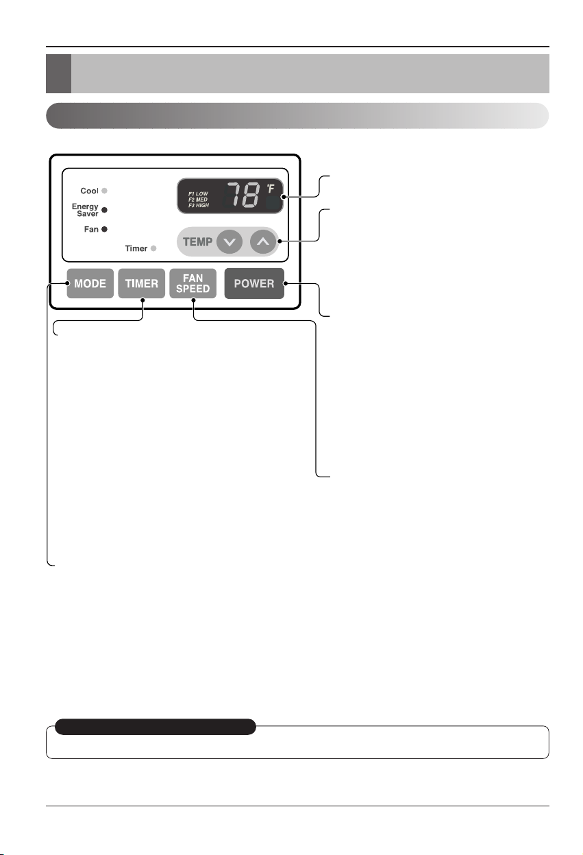
18 Climatiseur de pièce
Instructions d'utilisation
Instructions d'utilisation
Commandes
Les commandes s'afficheront comme suit:
RÉCEPTION SIGNAL DE
LA COMMANDE À DISTANCE
MISE SOUS TENSION
MODE
-
Appuyez sur ce bouton pour changer le mode de fonctionnement. La position change dans l’ordre qui suit
COOL
→
ENERGY SAVER → FAN
- COOL :
• le ventilateur tourne en permanence pour assurer un refroidissement normal continu.
-
ENERGY SAVER
:
• Le ventilateur s’arrête quand le compresseur arrête de produire du froid. Environ toutes les 3 minutes, le
ventilateur va se rallumer et le climatiseur va vérifier la température de la pièce pour déterminer s’il doit, ou
non, se remettre en marche.
- FAN :
• Seul le ventilateur fonctionne.
MINUTERIE (TIMER)
- HEURE D'ARRET (SHUT-OFF TIME)
• Vous utiliserez d'habitude la fonction Heure
d'Arrêt(shut-off time) lorsque vous dormez.
• Si l’appareil se fonctionne, utilisez la Minuterie pour
régler le nombre des heures jusqu’il s’arrête.
• Pour votre confort de sommeil, une fois que l'heure
est réglée, la Température de réglage augmentera
2°F après 30 minutes, et de nouveau après encore
30 minutes.
• Appuyez sur le bouton Minuterie pour avancer le
réglage de : 1 Heure
→
2 Heures → .... → 12 Heures
au maximum.
- HEURE DE DEMARRAGE (START TIME)
• Si l’appareil est arrêté, utilisez la Minuterie pour
régler le nombre des heures avant qu’il démarre.
• Appuyez sur le bouton Minuterie pour avancer le
réglage de : 1 Heure
→
2 Heures → .... → 12 Heures
au maximum.
RÉGLAGE TEMPÉRATURE
• Pour allumer le climatiseur, appuyez sur ce
bouton.
• Pour éteindre le climatiseur, appuyez à
nouveau sur ce bouton.
• Ce bouton est prioritaire sur n’importe quel
autre bouton.
• Quand vous allumez le climatiseur pour la
première fois, l’appareil est en position
Froid, le ventilateur en vitesse rapide et la
température réglée à 72°F.
VITESSE DU VENTILATEUR
• Chaque fois que vous appuyez sur ce bouton,
la position change dans l’ordre qui suit
{Rapide → Lente → Moyenne → Rapide}
• Utilisez ce bouton pour contrôler
automatiquement la température de la
pièce. La température peut être réglée
entre 60°F et 86°F avec une précision au
degré près.
• La programmation apparaît sur l’écran.
REDEMARRAGE AUTOMATIQUE
Quand le courant revient après une coupure d’électricité, le climatiseur recommencera à fonctionner selon les derniers réglages.
Page 43

Manuel de l'utilisateur 19
FRANÇAIS
Instructions d'utilisation
Télécommande
La télécommande et le tableau de commande auront l'apparence d'une des deux illustrations suivantes.
Power
Temp
Fan Speed
Timer Mode
MISE EN MARCHE
• Pour mettre en marche le climatiseur, appuyez sur ce bouton
• Pour éteindre le climatiseur, appuyez sur ce bouton à nouveau
• Ce bouton est prioritaire sur n’importe quel autre bouton
• Quand vous allumez le climatiseur pour la première fois, l’appareil est en
position Froid, le ventilateur en vitesse rapide et la température réglée à 72°F.
• Redémarrage automatique
Quand le courant revient après une coupure d’électricité, le climatiseur
recommencera à fonctionner selon les derniers réglages.
RÉGLAGE DE LA TEMPÉRATURE
• Utilisez ce bouton pour contrôler automatiquement la température de la pièce.
La température peut être réglée entre 60°F et 86°F avec une précision au
degré près.
• La programmation apparaît sur l’écran.
VITESSE DU VENTILATEUR
• Chaque fois que vous appuyez sur ce bouton, la position change dans
l’ordre qui suit (Rapide → Lente → Moyenne → Rapide)
PROGRAMMATEUR
- Arrêt programmé
• Vous utiliserez généralement cette fonction lorsque vous dormirez
• Si le climatiseur est en marche, utilisez le programmateur pour régler le nombre
d’heures avant l’arrêt de l’appareil.
• Pour votre confort, une fois que l’heure limite est passée, la température réglée
augmentera de 2°F au bout de 30 minutes et au bout d’une heure.
• Appuyez sur le bouton Programmateur pour avancer la sélection dans l’ordre qui
suit : 1 Heure
→
2 Heures → …… → 12 Heures maximum.
- Démarrage programmé
• Si le climatiseur est éteint, utilisez le programmateur pour régler le nombre
d’heures avant la mise en marche de l’appareil.
• Appuyez sur le bouton Programmateur pour avancer la sélection dans
l’ordre qui suit : 1 Heure
→
2 Heures → …… → 12 Heures maximum.
MODE
- Appuyez sur ce bouton pour changer le mode de fonctionnement. La position change dans l’ordre qui suit
COOL
→
ENERGY SAVER → FAN
- COOL :
• le ventilateur tourne en permanence pour assurer un refroidissement normal continu.
- ENERGY SAVER
• Le ventilateur s’arrête quand le compresseur arrête de produire du froid. Environ toutes les 3 minutes, le
ventilateur va se rallumer et le climatiseur va vérifier la température de la pièce pour déterminer s’il doit, ou
non, se remettre en marche.
- FAN :
• Seul le ventilateur fonctionne
Page 44

20 Climatiseur de pièce
Instructions d'utilisation
TIREZ POUR OUVRIR / POUSSEZ POUR FERMER
Ventilation
Directiondel’air
Le levier de ventilation se trouve à droite de la sortie d’air.
Le levier de ventilation doit être en position CLOSE (FERMÉ)afin
de conserver les meilleures conditions de refroidissement.
Réglez le levier de ventilation sur la position OPEN (OUVERT) s’il
faut de l’air frais dans la pièce.
Le registre s’ouvre et l’air est rejeté dehors.
La direction de l’air peut être réglée à votre guise en déplaçant les volets horizontal et vertical.
• COMMANDE DE LA DIRECTION DE
L’AIR HORIZONTALE
Pour régler la direction de l’air horizontale, déplacez
le volet vertical.
Le levier du volet vertical se trouve sur les côtés
droitetgauchedelasortied’air.
• COMMANDE DE LA DIRECTION DE
L’AIR VERTICALE
Pour régler la direction de l’air verticale, déplacez le
volet horizontal.
Comment insérer les piles
1. Enlevez le couvercle situé surlapartiearrière
de la télécommande.
2. Insérezdeuxpiles.
• Veillez à ce que les pôles (+) et (-) soient dans
la position correcte.
• Assurez-vous que les deux piles soient
neuves.
3. Replacez le couvercle.
• N’utilisez pas de piles
rechargeables. De telles piles
diffèrent des piles standard sèches
dans leur forme, dimensions et
performance.
• Enlevez les piles de la
télécommande si le climatiseur va
rester inutilisé pendant une longue
période.
Page 45

Manuel de l'utilisateur 21
FRANÇAIS
Entretien et réparations
Entretien et réparations
Nettoyage du filtre à air
Comment monter la grille avant sur le boîtier
ÉTEIGNEZ LE CLIMATISEUR ET RETIREZ LA FICHE DE LA PRISE DE COURANT.
Le filtre à air doit être contrôlé au moins deux fois par mois pour
vérifier si le nettoyage est nécessaire.
Des particules bloquées dans le filtre s’accumulent et peuvent
bloquer le flux de l’air. Cela réduit la capacité de refroidissement et
provoque aussi une accumulation de givre sur les bobines de
refroidissement.
Si le filtre est endommagé, vous devez le remplacez
immédiatement. Des filtres de remplacement sont disponibles
auprès de votre représentant, de votre revendeur et des centres
d’assistance autorisés.
1. Ouvrez la grille interne vers le bas en tirant sur le sommet de la
grille.
2. Enlevez le filtre à air du groupe grille avant en tirant délicatement
vers le haut le filtre.
3. Lavez le filtre en utilisant de l’eau tiède à moins de 40°C
(104°F).
4. Agitez délicatement le filtre pour éliminer complètement l’eau.
Remettez en place le filtre.
La grille avant peut être enlevée pour le nettoyage ou pour contrôler le modèle et le numéro de série.
Pour votre sécurité, montez la grille avant en suivant les procédures suivantes.
1. Baissez la grille avant à partir du sommet du boîtier.
2. Poussez les extrémitésdelagrilleavantversle
boîtier afin d’insérer les languettes de la grille dans
le boîtier.
3. Ouvrez la grille interne.
4. Serrez les vis à travers la grille avant dans le
plateaudelaboîte de contrôle.
5. Fermez la grille interne.
Page 46

22 Climatiseur de pièce
Entretien et réparations
Problèmes fréquents et Solutions
Guide de dépannage
Fonctionnement normal
Les conseils de dépannage vous permettent d’épargner du temps et de l’argent !
Consultez le diagramme ci-dessous avant de contacter le servie après-vente.
• Il se peut que vous entendiez un cliquetis provoqué par l’accumulation d’eau dans le condenseur pendant des jours pluvieux
ou d’humiditéélevée. Cette fonction a été conçue pour enlever l’humidité et rendre l’appareil plus performant.
• Il se peut que vous entendiez un déclic du thermostat lorsque le cycle du compresseur démarre ou s’arrête.
• De l’eau s’accumule dans bac à condensats pendant les jours pluvieux ou d’humiditéélevée. L’eau peut déborder et
s’écouler par le côté extérieur de l’unité.
• Il se peut que le ventilateur fonctionne même si le compresseur est arrêté.
Problème Causes possibles Solution
■ Le climatiseur est
débranché.
■
Le fusible a sauté ou le
disjoncteur s’est déclenché.
■ Panne d’électricité
■ Le dispositif d’interruption
du courant est déclenché.
■ Le flux d’air est restreint.
■ La commande TEMP est
réglée sur un numéro trop
élevé.
■ Le filtre à air est sale.
■
Il est probable que la
température de la pièce ait été
très chaude avant la mise en
marche du climatiseur.
■ L’air froid s’échappe.
■
Les serpentins de
refroidissement se sont givrés.
■
Le givre bloque la circulation de
l’air et empêche le climatiseur
de refroidir la pièce.
• Assurez-vous que la fiche électrique du climatiseur est
convenablement insérée dans la prise murale.
• Vérifiez le coffret du disjoncteur/les fusibles de la maison et
remplacez au besoin les fusibles ou redémarrez le
disjoncteur.
• En cas de panne de courant, tournez la commande de
mode à OFF. Une fois le courant rétabli, attendez 3 minutes
avant de remettre le climatiseur en marche, pour éviter un
dysfonctionnement par surcharge du compresseur.
• Appuyez sur la touche RESET situéesurlaprise
d’alimentation. Si la touche RESET n’enclenche pas,
interrompez l’utilisation du climatiseur et contactez un
technicien qualifié.
• Veillez à ce qu’aucun rideau, store ni meuble ne bloque la
partie frontale de l’appareil.
• Réglez la commande TEMP sur un numéro inférieur.
• Nettoyez le filtre à air au moins tous les quinze jours.
Référez-vous à la section “Instructions d’utilisation”.
• Lorsque vous allumez le climatiseur, vous devez attendre
un moment jusqu’à ce que la température de la pièce
commence à refroidir.
• Vérifiez si les registres des bouches chauffage et les
retours d’air froid sont fermés.
• Réglez l’orifice de ventilation du climatiseur sur la position
“FERMÉ’’.
• Référez-vous à la section “Givrage du climatiseur‘’ ci-
dessous.
•
Réglez la commande de mode sur ‘High Fan’ ou ‘High Cool’
avec une température élevée.
Le climatiseur ne
démarre pas
Le climatiseur ne
refroidit pas
comme il devrait
Givrage du
climatiseur
Page 47

FRANÇAIS
Manuel de l'utilisateur 23
Pour les modèles installéshorsl'Amérique du Nord. Pour les climatiseurs achetés pour usage hors
l'Amérique du Nord, le fabricant ne donne aucune garantie implicite ou explicite. Consultez votre revendeur
pour connaître les termes des garanties données par l’importateur dans votre pays.
Si vous avez déjà lu la brochure d'Installation et Fonctionnement en entier et qu'il vous semble qu'il faut faire
appel au service technique, téléphonez au
1-877-755-7932
ou bien écrivez à:
Heat Controller Inc.
1900 Wellworth Ave. Jackson, MI 49203
Preuve de la Date d'Achat
Il est la responsabilité du consommateur d'établir la date d'achat original pour se prévaloir de la garantie. A
cette fin, nous recommandons de conserver une facture de vente, un chèque payé ou d'autres justificatifs de
paiement appropriés.
Si vous avez des questions supplémentaires, vous pouvez téléphoner au 1-517-787-2100
ou adressez-vous par e-mail à customerservice@heatcontroller.com ou à techservice@heatcontroller.com
Téléphonez au (517) 787-2100 pour obtenir des pièces de rechange au-delà de la période de garantie.
Page 48

24 Climatiseur de pièce
Note
Page 49
Serie
"En pared"
Información importante
HEAT CONTROLLER, INC.
• Lea detenidamente y en su totalidad este manual antes de poner en funcionamiento la unidad.
• Póngase en contacto con un técnico de mantenimiento cualificado para que realice la instalación,
reparación y mantenimiento de esta unidad.
• Este aparato no está destinado para ser usado por niños pequeños o personas que requieran
supervisión.
• Deberá supervisarse a los niños pequeños para asegurarnos de que no juegan con el aparato.
Modelos: BG-81A
BG-101A
BG-123A
Page 50
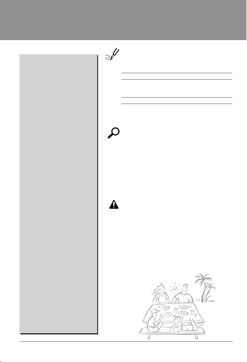
2 Aire Acondicionador
Manual del usuario del acondicionador de aire tipo Ventana
TABLA DE CONTENIDOS
PARA SUS ARCHIVOS
Escriba aquí el modelo y número de serie:
Modelo n°:
Serie n°:
Puede encontrar estos datos en la etiqueta situada en el
lateral de cada unidad.
Nombre del distribuidor:
Fecha de compra:
■ Adjunte su recibo a esta página con la grapadora para
el momento que lo necesite para probar la fecha de su
adquisición o para la validación de la garantía.
LEAESTEMANUAL
En su interior encontrará muchos consejos útiles sobre la
utilización y mantenimiento de su acondicionador de aire.
Unos pocos cuidados por su parte le pueden ahorrar
mucho tiempo y dinero durante la vida de su
acondicionador de aire.
Enlatabladeconsejosparalasoluciónrápidade
problemas encontrará muchas respuestas a los problemas
más habituales. Si revisa primero nuestra Tab la d e
Consejos para la solución rápida de problemas, tal vez no
necesite llamar nunca al servicio técnico.
PRECAUCIÓN
• Póngase en contacto con un técnico del servicio
autorizado para realizar la reparación y
mantenimiento de esta unidad.
• Póngase en contacto con un instalador para realizar
lainstalacióndeestaunidad.
• Cuando se va a cambiar el cable eléctrico, el trabajo
de reemplazamiento debe ser realizado únicamente
por personal autorizado, utilizando las piezas de
cambio genuinas únicamente.
• El trabajo de reemplazamiento debe ser realizado de
acuerdo con el Código Eléctrico Nacional
únicamente por personal autorizado.
Precauciones de Seguridad ...........3
Antesdeponerelequipoen
funcionamiento................................7
Introducción.....................................8
Seguraida Electrica.........................9
Instalacion......................................11
Instruccionnes de
Funcionamiento.............................18
Cuidado y Mantenimiento ............21
Page 51

Manual del Propietario 3
ESPAÑOL
Precauciones de Seguridad
Precauciones de Seguridad
Paraevitarlesionesalusuariooaotraspersonasydañosalapropiedad,estasinstrucciones
estén seguirse.
■
Una operación incorrecta por ignorar las instrucciones provocará lesiones o daños. La seriedad se clasifica
por las siguientes indicaciones.
■ Significados de los símbolos utilizados en este manual.
Este símbolo indica la posibilidad de muerte o de seria lesión.
Este símbolo indica sólo la posibilidad de lesiones o daños a la propiedad
ADVERTENCIA
■ Instalación
No hacer.
Siga estas instrucciones.
No utilice un cable de
alimentación, enchufe o una
toma suelta que esté dañada.
• De lo contrario, podría provocar
un incendio o descarga
eléctrica.
Enchufesiempreaun
tomacorriente que tenga
toma a tierra.
• De lo contrario, podría provocar
un incendio o descarga
eléctrica.
No modifique ni alargue el
cable de alimentación.
• De lo contrario, puede provocar
una descarga eléctrica o
incendio debido a la
generación de calor.
No desmonte ni modifique
los productos.
• Puede ocasionar fallos y una
descarga eléctrica.
Tenga cuidado al
desembalar e instalar el
aparato.
• Los bordes afilados pueden
provocar lesiones.
No use el cable de alimentación
cerca gas inflamable o
materiales combustibles tales
como la gasolina, benceno,
disolvente, etc.
• Podría ocurrir una explosión o
incendio.
Gasolin
ADVERTENCIA
PRECAUCION
Page 52

4 Aire Acondicionador
Precauciones de Seguridad
■ Operación
No ponga el cable de
alimentación cerca de un
calentador.
• Puede ocasionar un incendio y
una descarga eléctrica.
No permita que entre agua
en las piezas eléctricas.
• Puede provocar fallos en el
producto o descargas
eléctricas.
Utilice un paño suave para
limpiar. No utilice cera,
disolventes o detergentes
fuertes.
•
La apariencia del aparato de aire
acondicionado puede deteriorar,
cambiar el color o desarrollar flujos
en las
superficies.
Wax
Thinner
Ventile bien la sala al usar
este aparato con una estufa,
etc.
• Puede ocurrir un falta de
oxígeno.
Apague el aparato y el
interruptor diferencial
primero antes de limpiar la
unidad.
•
Debido a que el ventilador gira a
alta velocidad durante el
funcionamiento, podría ocasionar
lesiones.
Apague el interruptor de
alimentación principal cuando
no vaya a utilizar el aparato
durante mucho tiempo.
• Evitará el arranque accidental y
la posibilidad de lesiones.
Desenchufe la unidad si oye
un sonido extraño, olores, o
si observa salir humo.
• De lo contrario, puede ocurrir
un incendio y un accidente por
descarga eléctrica.
No abra la parrilla de
entrada al aparato mientras
está en funcionamiento.
• De lo contrario, pueden ocurrir
descargas eléctricas y fallos.
Sientraaguaenelproducto,
apague el interruptor de la
carcasa principal del aparato.
Póngase en contacto con el
centro de servicio despuésde
haber sacado el enchufe del
tomacorriente.
No use el cable de alimentación
cerca gas inflamable o materiales
combustibles tales como la
gasolina, benceno, disolvente, etc.
• Puede ocasionar una explosión
o descarga eléctrica.
No comparta el
tomacorriente con otros
electrodomésticos.
•
De lo contrario, puede provocar una
descarga eléctrica o incendio debido
a la generación de calor.
Saque el enchufe en caso de
necesidad, sosteniendo la
cabeza del enchufe y no lo
toque con las manos mojadas.
•
De lo contrario, podría provocar un
incendio o descarga eléctrica.
Page 53

Manual del Propietario 5
ESPAÑOL
Precauciones de Seguridad
ADVERTENCIA
■ Instalación
No opere ni detenga la
unidad insertando o
estirando de enchufe.
• De lo contrario, puede provocar
una descarga eléctrica o
incendio debido a la
generación de calor.
No dañeniuseunenchufe
de alimentaciónno
especificado.
• Provocará descargas eléctricas
o incendios.
No toque el producto con
las manos mojadas o en un
ambiente húmedo.
• Provocará descargas
eléctricas.
Sostenga el enchufe por su
cabeza al sacarlo.
• Podría ocasionar una descarga
eléctrica y daños.
Cuando haya un escape de
gas, abra la ventana para
ventilar antes de poner en
marcha la unidad.
• De lo contrario, podría ocurrir
una explosión o incendio.
No toque las partes
metálicas del aparato al
sacar el filtro del aire.
• Son puntiagudas y pueden
provocar lesiones.
Instale el producto de modo que el ruido o
el aire caliente producido por la unidad
externa no moleste a los vecinos.
• De lo contrario puede dar lugar a disputas
vecinales.
Mantenga nivelado el producto al instalarlo.
• De lo contrario se podría causar vibraciones o
escapes de agua.
Page 54

6 Aire Acondicionador
Precauciones de Seguridad
Nosesubaalaunidad
interior/exterior ni coloque
objetos sobre la misma.
• Puede lesionarse al caerse del
aparato o al caerse los objetos
que haya colocado.
Inserte siempre el filtro
correctamente.
Límpielo cada dos semanas.
• El funcionamiento sin filtros
puede provocar fallos.
No beba el agua que drena
el aparato de aire
acondicionado.
No ponga plantas ni
animales en la trayectoria
que recorrerá el aire
caliente.
• Podría ocasionar lesiones.
No bloquee la entrada ni la
salida del flujo de aire.
• Puede causar una avería en el
aparato.
Utilice un paño suave para
limpiar. No utilice cera,
disolventes o detergentes
fuertes.
•
La apariencia del aparato de aire
acondicionado puede deteriorar,
cambiar el color o desarrollar flujos
en las superficies.
Tenga cuidado para no
tocar los bordes
puntiagudos al instalar.
• Podría ocasionar lesiones.
Evite un enfriamiento
excesivo y ventile en
ocasiones.
• De lo contrario, podría dañar su
salud.
No introduzca la mano ni
barras en la entrada o salida
del aire durante el
funcionamiento del aparato.
• De lo contrario, podrían ocurrir
lesiones personales.
■ Operación
Page 55

Antes de poner el equipo en funcionamiento
Manual del Propietario 7
ESPAÑOL
Antes de poner el equipo en funcionamiento
1. Póngase en contacto con un especialista para realizar la instalación.
2. Enchufe correctamente la toma de alimentación.
3. Utilice un circuito dedicado.
4. No utilice un cable alargador.
5. No inicie/cese el funcionamiento enchufando/desenchufando el cable
eléctrico.
6. Si el cable/enchufe está dañado, sustitúyalo solo por una pieza autorizada.
1. Estando expuesto a la circulación directa de aire durante un extenso período
de tiempo podría resultar peligroso para su salud. No exponga a las personas,
animales domésticos, o a las plantas a la circulación de aire durante largos
períodos de tiempo.
2. Debido a la probabilidad de falta de oxígeno, ventile el cuarto cuando esté
utilizado el aparato junto con estufas u otros aparatos de calefacción.
3. No utilice este aire acondicionado con propósitos especiales no especificados
(Ej.: conservación de dispositivos de precisión, comida, animales domésticos,
plantas y objetos de arte). Tal uso podría dañar los artículos.
1. No toque las piezas metálicas de la unidad al retirar el filtro. Manejar aristas
afiladas de metal puede causar lesiones.
2. No utilice el agua para limpiar el interior del aire acondicionado. La exposición
al agua puede destruir el aislamiento, conduciendo a posibles descargas
eléctricas.
3. Al limpiar la unidad, asegúrese antes de que la electricidad y el interruptor
están apagados. El ventilador rota a muy alta velocidad durante el
funcionamiento del equipo. Existe la posibilidad de lesiones si acciona
accidentalmente la electricidad de la unidad mientras limpia el interior de la
unidad.
Para cuestiones de reparación y mantenimiento, póngase en contacto con su
distribuidor de servicio autorizado.
Preparación para el funcionamiento
Uso
Limpieza y mantenimiento
Servicio
Page 56

8 Aire Acondicionador
Introducción
Este símbolo lo advierte de un peligro de accidente por
corriente eléctrica.
Este símbolo lo adiverte de un peligro que pueda causar un
daño del ventliador.
Este símbolo significa condicciones especiales.
CONSEJO
Introducción
Símbolos Utilizados en Este Manual
Características
Este aparato debería instalarse de acuerdo con las normas del Código Eléctrico Nacional.
EL SOPORTE DE PARED Y
LA REJILLA POSTERIOR
(incluido opcionalmente con su unidad)
MONTAJE DEL SOPORTE DE PARED
(Incluyendo rejilla posterior de aluminio)
REJILLA POSTERIOR
(Rejilla posterior
de aluminio)
FILTRO DE AIRE
REJILLA DE ENTRADA
DEFLECTOR VERTICAL DE AIRE
(Rejilla de ventilación horizontal)
(Toma de aire)
DEFLECTOR HORIZONTAL DE AIRE
(Rejilla de ventilación vertical)
CONTROL DEL ORIFICIO DE VENTILACIÓN
EL UNIDAD
DESCARGA
DE AIRE
ARMARIO
REJILLA
FRONTAL
Page 57

Seguraida Electrica
Manual del Propietario 9
ESPAÑOL
Seguraida Electrica
Datos Electricos
No presione nunca el botón de prueba durante el
funcionamiento, de lo contrario el enchufe podría
resultar dañado.
Este dispositivo contiene productos químicos,
incluyendo plomo, conocido en el estado de
California como producto cancerígeno y causante de
defectos de nacimiento y otros daños al sistema
reproductor.
Lávese bien las manos tras manipular el dispositivo.
No desmonte, modifique ni sumerja en agua este
enchufe.
Si el dispositivo se activara, deberá corregir la causa
antes de volver a utilizarlo.
Los hilos conductores dentro del cable están rodeados
por blindajes, que supervisan la corriente de fuga.
Estos blindajes no están puestos a tierra.
Examine periódicamente el cable en busca de
cualquier daño. No utilice este producto si los blindajes
resultaran expuestos.
Eviteelriesgodedescargaseléctricas; esta unidad no
puede ser reparada por el usuario por ser resistente y
a prueba de alteraciones. Manipular la porción sellada
de la unidad anulará todas las garantías y quejas de
rendimiento. Esta unidad no está diseñada para su uso
como un interruptor de encendido-apagado.
La forma puede ser diferente según su modelo.
CONSEJO
NOUSECABLEDEEXTENSIÓNENUNIDADES
DE 208, 230, AND 208/230 VOLTIOS.
Todo el cableado deberá realizarse de acuerdo
con los códigos y reglamentos eléctricos
locales.
El cableado domésticodealuminiopodría
ocasionar problemas especiales. Consulte a un
electricista calificado.
CONSEJO
115V~ 230V~
Utilice el enchufe de la pared Consumo de Energía
Standard 125V, enchufe de 3
Líneas de 15A, 125V AC
Standard 250V, enchufe de 3
Líneas de 15A, 250V AC
Standard 250V, enchufe de 3
Líneas de 20A, 250V AC
Utilice un fusible de
15AMP. o un
Interruptor de 15AMP.
Utilice un fusible de
20AMP. o un
Interruptor de 20AMP.
El cable de alimentación puede incluir un
dispositivo interruptor de corriente. La carcasa
del enchufe cuenta con un botón de prueba y
otro de reinicio. El dispositivo debe comprobarse
periódicamente presionando primero el botón
TEST y después RESET.
Si el botón TEST no se desconecta o si el botón
RESET no permanece activo, suspenda el uso
del aire acondicionado y póngase en contacto
con un técnico de servicio cualificado.
Page 58

10 Aire Acondicionador
Seguraida Electrica
IMPORTANTE
(FAVORLEA CON ATENCIÓN)
POR LA SEGURIDAD PERSONAL DEL USUARIO, ESTE
APARATO DEBE SER DEBÍDAMENTE NEUTRALIZADO.
El cordón de energíadeéste aparato esta equipado
con tres patas(cable a tierra). Utilice éste con un
enchufe de pared de tres salidas(a tierra) para
minimizar el peligro de choque eléctrico. El cliente
debe revisar el receptor de pared y el circuito por un
electricista calificado para asegurarse que la
recepción esta debidamente neutralizada.
NO CORTE O REMUEVA LA TERCERA PATA(GROUND)
DEL ENCHUFE.
A. SITUACIONES EN LAS CUALES EL APARATO
ES DESCONECTADO OCASIONALMENTE:
Debido al peligro potencial, nosotros no
recomendamos el uso de adaptadores. Sin embargo,
si usted desea utilizar un adaptador, una CONEXIÓN
TEMPORAL, puede ser
efectuada. Utilice adaptadores UL, disponibles en la
mayoría de los estable cimientos de
herramientas. La pata mas grande del adaptador
debe ser alineada con la pata mas grande del
interruptor para asegurarse una polarización
adecuada.
Adaptar la terminal del ground del adaptador a
la cubierta de la pared con un
tornillo no neutraliza el aparato a menos que la
cubierta del tornillo sea de metal, u no sea
insolada, y el receptor de pared este
neutralizado a través del alambrado del la casa.
El cliente debe hacer verificar el circuito por un
electricista calificado para asegurarse que el
receptor esta debidamente neutralizado.
Desconecte el cordóndeenergía del adaptador,
utilizado una mano en cada uno. De lo contrario, la
terminal del adaptador puede romperse. NO UTILICE el
aparato con un enchufe roto.
B. SITUACIONES EN LAS CUALES EL APARATO
ES DESCONECTADO CON
FRECUENCIA.
No utilice un adaptador en estas circunstancias.
Desconectar el cordóndeenergía con frecuencia lo
llevará al eventual rompimiento de la terminal de
neutralización. La saluda de energíadelapared
debe ser reemplazada por una salida de tres
patas(neutralizada).
USO DE EXTENSIONES
Debido al peligro potencial, no recomendamos la
utilizacióndeextensiones.Sinembargo,siusted
desea utilizar una extensión, utilice una
certificada por CSA/UL de tres alambres,
catalogada 15A, 125V.
Seguraida Electrica
Page 59

Manual del Propietario 11
ESPAÑOL
Instalacion
Instalacion
Retire los materiales de embalaje del soporte de pared de
pared y la cinta del aire acondicionado.
REQUISITOS DE INSTALACIÓN
Si utiliza un soporte de pared de pared ya existente,
deberá medir sus dimensiones. Instale el nuevo aire
acondicionado según estas instrucciones de instalación
para lograr el mejor funcionamiento. Todos los soporte de
pared de pared utilizados para montar el nuevo aire
acondicionado deben estar en buenas condiciones
estructurales y contar con una rejilla trasera para conectar
el nuevo aire acondicionado de forma segura. (FIG. 1)
Con el soporte de pared HCI (incluido opcionalmente
con su unidad), podrá mantener el mejor rendimiento del
nuevo aire acondicionado. (FIG. 2)
SERVICIO ELÉCTRICO
Compruebe su servicio eléctrico disponible. La fuente de
alimentación disponible debe ser igual que la que se
muestra en la placa de identificacióndelaunidad
(encontrada en el lado izquierdo de la carcasa).
Todos los modelos están equipados con un enchufe de
tres dientes para proporcionar el servicio apropiado y
poner a tierra el positivo de forma segura. No cambie el
enchufe de ninguna manera. No utilice un enchufe
adaptador. Si su enchufe de pared actual no admite su
enchufe,llameaunelectricistacualificadopararealizar
las correcciones necesarias. GUARDE LA CAJA DE
CARTÓN para el almacenamiento y este MANUAL DEL
PROPIETARIO para futuras referencias. El cartónesla
mejor manera de almacenar la unidad durante el invierno
o cuando no esté en uso.
HARDWARE DE INSTALACIÓN
14-13/32"
(366 mm)
24"(610 mm)
18-15/32"(468 mm)
20-3/32"
(511 mm)
• Guantes ceñidos
adecuados
• Destornillador estándar
• Destornillador de estrella
• Alicates
• Cuchillo afilado
• Llave inglesa abierta o
ajustable de 3/8-pulgadas
• Enchufeycarretedetuerca
hexagonal de 1/4- pulgadas
• Cinta métrica
• Ta la d r o e l éctrico
• Boca de taladro de 1/4-
pulgadas
FIG. 1
Aire acondicionado
ARTÍCULO
NOMBRE DE LAS PIEZAS Q'TY
1
REJILLA DE PLÁSTICO 1
2
TIRA VERTICAL DE AISLAMIENTO 1
3
TIRAS ENVOLVENTES DE AISLAMIENTO
2
4
TIRA HORIZONTAL DE AISLAMIENTO 1
5
BLOQUE DE APOYO 2
6
COMPUERTA 1
7
MARCO DE AJUSTE 2
8
CUÑA2
9
TUERCASDEPLÁSTICO Y TORNILLOS DE ARANDELA
4
FIG. 2
Soporte de pared
HCI
Para evitar riesgos de daños corporales, materiales, o daños
al producto debidos al peso de este dispositivo y a los bordes
afilados que pueden estar expuestos:
• Los aires acondicionados tratados en este manual
representan un peligro por peso excesivo. Son necesarias
dos o más personas para desplazar e instalar la unidad.
Para evitar lesiones o grandes esfuerzos, utilice las técnicas
de elevación y desplazamiento para mover la unidad.
• Examinar cuidadosamente la ubicación donde el aire
acondicionado vaya a ser instalado. Asegúrese de que
aguantará el peso de la unidad a lo largo de un extenso
períododetiempo.
• Manipule con cuidado el aire acondicionado. Utilice los
guantes protectores siempre que levante o desplace la
unidad. EVITE las aristas afiladas de metal de las bobinas
frontal y posterior.
• Asegúrese de que el aire acondicionado no se caiga durante
la instalación.
HERRAMIENTAS NECESARIAS:
1
8
9
2 4
2 opciones de tamaño
3
2 opciones de tamaño
5
6
7
25-7/8"
(656 mm)
15-17/32"
(394 mm)
Rejilla de aluminio
16-23/32"
(425 mm)
Page 60

12 Aire Acondicionador
Instalacion
INSTALACIÓN
• Escoja una ubicaciónquepermitaalaireacondicionado
soplar hacia el área que desee. Una buena instalación,
prestando especial atenciónalaposicióncorrectadela
unidad reducirá la necesidad de reparaciones.
ARTÍCULOS EN EL HARDWARE DE
INSTALACIÓN
Usted puede no necesitar todas las piezas del conjunto.
Descarte las piezas que no utilice
CÓMO INSTALAR
Identifique el soporte de pared existente antes de
instalar la unidad según la lista.
Todos los soporte de pared utilizados para montar el
nuevo aire acondicionado deben estar en condiciones
estructurales sanas y tener una rejilla posterior que se
acople con seguridad al soporte de pared, o una pestaña
posterior que sirva como freno para el aire
acondicionado.
Desmonte el antiguo aire acondicionado del soporte
de pared existente.
Limpie el interior del soporte de pared existente. (No
toque el sellado.)
El soporte de pared se estar firmemente sujeto a la pared
antes de instalar el aire acondicionado. Utilice los clavos o
tornillos a través del soporte de pared, si fuera necesario.
Vuelva a pintar el soporte de pared si fuera necesario.
Prepare el soporte de pared para la instalacióndela
unidad. Si usted piensa utilizar el soporte de pared
existente, y no es HCI, utilice el procedimiento B ó C
a continuación.
Instale la nueva unidad en el soporte de pared.
Al finalizar la instalación, la unidad de sustitución DEBE
tener una pendiente hacia atrássegúnseilustra.Para
lograr una pendiente de 1/4", retire el envoltorio de las
cuñas de 11-13/16" y acóplelas segúnsemuestraa
continuación en la FIG. 3. Coloque el extremo másalto
de la cuña en la parte frontal de la base del soporte de
pared.
CONSEJO
1
2
3
4
5
6
1/4"
Soporte
de pared
FRENTAL
UNIDAD
COLOCACIÓN DE LA CUÑA INSTALACIÓN DE LA UNIDAD
1"de
alto
3/4"de alto
Cuña
6" 6"
FIG. 3
Recomendamos encarecidamente que desmonte el viejo
soporte de pared y la instalación de un nuevo soporte
de pared HCI.
Si decide mantener el soporte de pared existente, tendrá
que redireccionar las rejillas de ventilaciónenlaparte
posterior de la ilustración del soporte de pared.
Recomendamos el uso de alicates. Si NO las redirecciona,
correelriesgodeunrendimientopobreodeaverías en el
producto.
Estas no están cubiertas bajo los términos de garantíade
HCI.
ARTÍCULO (pulgadas) Cant.
Rejilla plástica 26
3
/
4
x16
1
/
2
1
Tira vertical de aislamiento 15
9
/
16
x1
3
/
8
x1
3
/
8
1
Tiras de aislamiento 67
1
/
8
x1
3
/
8
x
25
/
32
1
envolventes 59
27
/
32
x1
3
/
8
x1
3
/
8
1
Tira horizontal de aislamiento
23
7
/32 x1
3
/
8
x1
3
/16 1
Bloque de apoyo 1
3
/
4
x1
3
/
8
x4
5
/
16
2
Compuerta 14 x 4
1
/
2
x
1
/
8
1
Cuña11
13
/
16
x1x
3
/
4
2
Marcodeajuste 2
Tornillos de arandela 4
Tu er c a s ( P l ástico) 4
Rejilla posterior 1
Marca
Dimensiones del soporte de pared (pulgadas)
Ancho Altura
Profundidad
White-Westinghouse
25-1/2 15-1/4
16, 17-1/2
Frigidaire
ó 22
Carrier (Serie 52F)
General Electric
26 15-5/8 16-7/8
/Hotpoint
Whirlpool 25-7/8 16-1/2
17-1/8
ó 23
Fedders/Emerson 27 16-3/4
16-3/4
ó 19-3/4
HCI 25-7/8 15-17/32 16-23/32
Emerson/Fedders 26-3/4 15-3/4 15
Carrier (Serie 51S) 25-3/4 16-7/8 18-5/8
Friedrich 27 16-3/4 16-3/4
Procedimiento Marca
Profundidad (pulgadas)
A HCI 16-23/32
White-Westinghouse
Frigidaire Carrier
16, 17-1/2
Carrier (Serie 52F)
ó 22
B
General Electric
16-7/8
/Hotpoint
Whirlpool 17-1/8 ó 23
Carrier (Serie 51S)
18-5/8
Fedders/Emerson
16-3/4
ó 19-3/4
C
Emerson/Fedders 15
Friedrich 16-3/4
Page 61

Manual del Propietario 13
ESPAÑOL
Instalacion
PROCEDIMIENTO A
Si está utilizando un nuevo soporte de pared
(incluido opcionalmente con su unidad), salte al
paso 3. Si no es así, instale la rejilla plástica. Corte
la rejilla plástica a 25-1/2" de ancho y 15-1/4” de
alto. Coloque la rejilla plástica en el interior del
soporte de pared en la pestaña posterior.
Apriete los 4 tornillos de la arandela para asegurar la
rejilla al soporte de pared. Si necesita tuercas
plásticas para montar la rejilla plástica en el interior
del soporte de pared, encontrará tuercas plásticas
en el equipo de instalación. Las tuercas están
instaladas en el interior del soporte de pared y están
presionando las perforaciones rectangulares de las
pestañas posteriores.
Retire el envoltorio de la tira vertical de aislamiento
15-9/16 x 1-3/8 x 1-3/8 y únala a la par te interior
derecha del soporte de pared según se muestra a
continuación. Retire el envoltorio de la tira de
aislamiento envolvente de 67-1/8 x 1-3/8 x 25/32 y
únala a la par te frontal interior del sopor te de pared
según se muestra a continuación.
Instale la nueva unidad en el soporte de pared.
Para el montaje, encaje la lengüeta de cada pieza
en la ranura de la otra pieza según se muestra a
continuación. Deslice la pieza sobre la parte frontal
del aire acondicionado hasta que el ajuste sea
rasante con el soporte de pared según se muestra a
continuación.
FIG. 4
Aislamiento envolvente
Aislamiento vertical
9 1/2"6"
Interior Exterior
FIG. 6
ó
FIG. 5
1
2
3
4
5
Pared
Ajuste (2EA)
FIG. 7
• Los aires acondicionados tratados en este manual
representan un peligro por peso excesivo. Son
necesarias dos o más personas para desplazar e
instalar la unidad. Para evitar lesiones o esfuerzos
excesivos, utilice las técnicas de levantamiento y
desplazamiento apropiadas al mover la unidad.
• Manipule con cuidado el aire acondicionado, tenga
cuidado de evitar cortes de las aristas afiladas de
metal de las bobinas frontal y posterior.
• Asegúrese de que el aire acondicionado no se caiga al
desmontarlo.
• Si la unidad no funciona tras la revisióndeinstalación,
asegúrese que el interruptor del circuito no se ha
disparado. Consulte la guíadesolucióndeaverías
para conocer el procedimiento de reinicio.
Page 62

14 Aire Acondicionador
Instalacion
PROCEDIMIENTO B
Redireccione las rejillas de ventilaciónenlaparte
posterior del soporte de pared a un ángulo de 60°
según muestra la FIG. 9. Recomendamos el uso de
alicates.
Si el soporte de pared ya cuenta con una rejilla
posterior, salte al paso 4. Si el soporte de pared no
tiene una rejilla posterior o un panel en rejilla, instale
la rejilla plástica del conjunto. Corte la rejilla plástica
a 25-1/2" de ancho y 15-1/4” de alto. Coloque la
rejilla plástica en la parte interior del soporte de
paredenlapestaña posterior.
Apriete los 4 tornillos de la arandela para asegurar la
rejilla al soporte de pared. Si necesita tuercas
plásticas para montar la rejilla plásticaenelinterior
del soporte de pared, encontrará tuercas plásticas
en el equipo de instalación. Las tuercas están
instaladas en el interior del soporte de pared y están
presionando las perforaciones cuadradas de las
pestañas posteriores.
Retire el envoltorio de la tira vertical de aislamiento
15-9/16 x 1-3/8 x 1-3/8 y únala a la parte interior
derecha del soporte de pared segúnsemuestraa
continuación. Retire el envoltorio de la tira de
aislamiento envolvente de 67-1/8 x 1-3/8 x 25/32 y
únala a la parte frontal interior del soporte de pared
segúnsemuestraacontinuación.
Si la profundidad de su soporte de pared es menor o
igual a 18", salte al paso 7. Si no, corte las
compuertas y los bloques de soporte segúnla
longitud"A"enlatablaacontinuación.
1
4
2
3
FIG. 9
Aislamiento envolvente
Aislamiento vertical
9 1/2"6"
Interior Exterior
FIG. 11
ó
FIG. 10
Rejillas de ventilación posteriores
(Perspectiva superior)
60°
60°
7
3
/
32
"
FIG. 8
Profundidad "D" del soporte
de pared existente (pulgadas)
Longitud "A"
(pulgadas)
Bloque
de apoyo
Compuerta
A
A
3
/
4
1-3/4
4
18 D 18-5/
8
18-5/
8
D 19-3/
4
19-3/4 D 22
5
Coloque la rejilla plástica
Apriete los tornillos
FIG. 12
Page 63
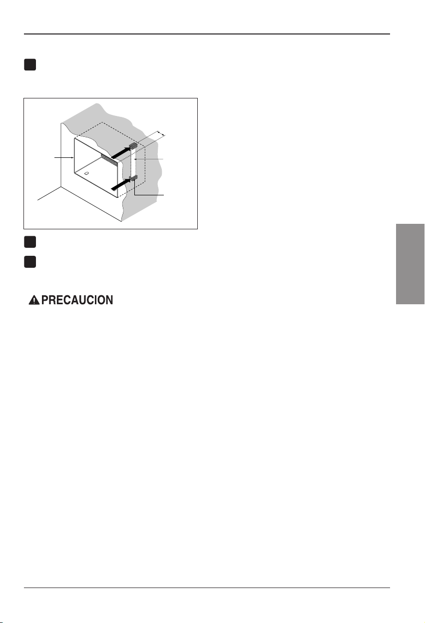
Manual del Propietario 15
ESPAÑOL
Instalacion
PROCEDIMIENTO B
Retire el envoltorio de los bloques de apoyo y
acóplelos al interior del soporte de pared como
muestra la FIG. 13. Deslice la compuerta en las
ranuras de los bloques de apoyo.
Instale la nueva unidad en el soporte de pared.
Ajuste la posiciónsegúndescribeelpaso6,
procedimiento A.
8
Pared
Soporte
de pared
Compuerta
(
7
3
/
32
"
)
Frontal
Bloque
de apoyo
FIG. 13
6
7
• Los aires acondicionados tratados en este manual
representan un peligro por peso excesivo. Son
necesarias dos o más personas para desplazar e
instalar la unidad.
Para evitar lesiones o esfuerzos excesivos, utilice
las técnicas de levantamiento y desplazamiento
apropiadas al mover la unidad.
• Manipule con cuidado el aire acondicionado, tenga
cuidado de evitar cortes de las aristas afiladas de
metal de las bobinas frontal y posterior.
• Asegúrese de que el aire acondicionado no se
caiga al desmontarlo.
• Si la unidad no funciona tras la revisiónde
instalación, asegúrese que el interruptor del circuito
no se ha disparado. Consulte la guíadesoluciónde
averías para conocer el procedimiento de reinicio.
Page 64

16 Aire Acondicionador
Instalacion
PROCEDIMIENTO C
Redireccione las rejillas de ventilaciónenlaparte
posterior del soporte de pared a un ángulo de 60°
según muestra la FIG. 14. Recomendamos el uso de
alicates.
Si el soporte de pared ya cuenta con una rejilla
posterior, salte al paso 4. Si el soporte de pared no
tiene una rejilla posterior o un panel en rejilla, instale
la rejilla plástica del conjunto. Corte la rejilla plástica
a 26-1/2" de ancho y 15-1/2” de alto. Coloque la
rejilla plástica en la parte interior del soporte de
paredenlapestaña posterior.
Apriete los 4 tornillos de la arandela para asegurar la
rejilla al soporte de pared. Si necesita tuercas
plásticas para montar la rejilla plásticaenelinterior
del soporte de pared, encontrará tuercas plásticas
en el equipo de instalación. Las tuercas están
instaladas en el interior del soporte de pared y están
presionando las perforaciones cuadradas de las
pestañas posteriores.
Retireelenvoltoriodelatirahorizontaldeaislamiento
de 23-7/32 x 1-3/8 x 1-3/16 y únala a la parte interior
derechadelsoportedeparedsegúnsemuestraa
continuación.Retireelenvoltoriodelatirade
aislamiento envolvente de 59-27/32 x 1-3/8 x 1-3/8 y
únala a la parte frontal interior del soporte de pared
segúnsemuestraacontinuación.
Si la profundidad de su soporte de pared es menor o
igual a 18", salte al paso 7. Si no, corte las
compuertas y los bloques de apoyo segúnlalongitud
"A" en la tabla a continuación.
Retire el envoltorio de los bloques de apoyo y únalos
al interior del soporte de pared como muestra la FIG.
19. Deslice la compuerta dentro de las ranuras en
los bloques de apoyo.
Profundidad "D" del soporte
de pared existente (pulgadas)
Longitud "A"
(pulgadas)
Bloque
de apoyo
Compuerta
A
A
3
/
4
1-3/4
4
18 D 18-5/
8
18-5/
8
D 19-3/
4
19-3/4 D 22
Pared
Soporte
de pared
Compuerta
Frontal
Bloque
de poyo
(7
3
/
32
")
FIG. 19
FIG. 18
1
4
2
3
FIG. 15
8 1/2"
Interior Exterior
Aislamiento envolvente
Aislamiento horizontal
FIG. 17
ó
FIG. 16
Rejillas de ventilación posteriores
(Perspectiva superior)
60°
7
3
/
32
"
60°
FIG. 14
5
6
Coloque la rejilla plástica
Apriete los tornillos
Page 65

Instalacion
Manual del Propietario 17
ESPAÑOL
PROCEDIMIENTO C
Para lograr una pendiente de posterior para el
drenaje de la unidad, retire el envoltorio de las
cuñas de 11-13/16" y acóplelas segúnsemuestra
a continuación en la FIG. 21. Coloque el extremo
másaltodelacuña en la parte frontal de la base
del soporte de pared.
Instale la nueva unidad en el soporte de pared.
Monte el ajuste segúnlodescritoenelpaso6,
procedimiento A.
8
9
7
FIG. 20
1" de
alto
3/4"
de alto
FIG. 21
• Los aires acondicionados tratados en este manual
representan un peligro por peso excesivo. Son
necesarias dos o más personas para desplazar e
instalar la unidad.
Para evitar lesiones o esfuerzos excesivos, utilice
las técnicas de levantamiento y desplazamiento
apropiadas al mover la unidad.
• Manipule con cuidado el aire acondicionado, tenga
cuidado de evitar cortes de las aristas afiladas de
metal de las bobinas frontal y posterior.
• Asegúrese de que el aire acondicionado no se
caiga al desmontarlo.
• Si la unidad no funciona tras la revisiónde
instalación, asegúrese que el interruptor del circuito
no se ha disparado. Consulte la guíadesolución
de averías para conocer el procedimiento de
reinicio.
Cuña (2EA)
6" 6"
Page 66
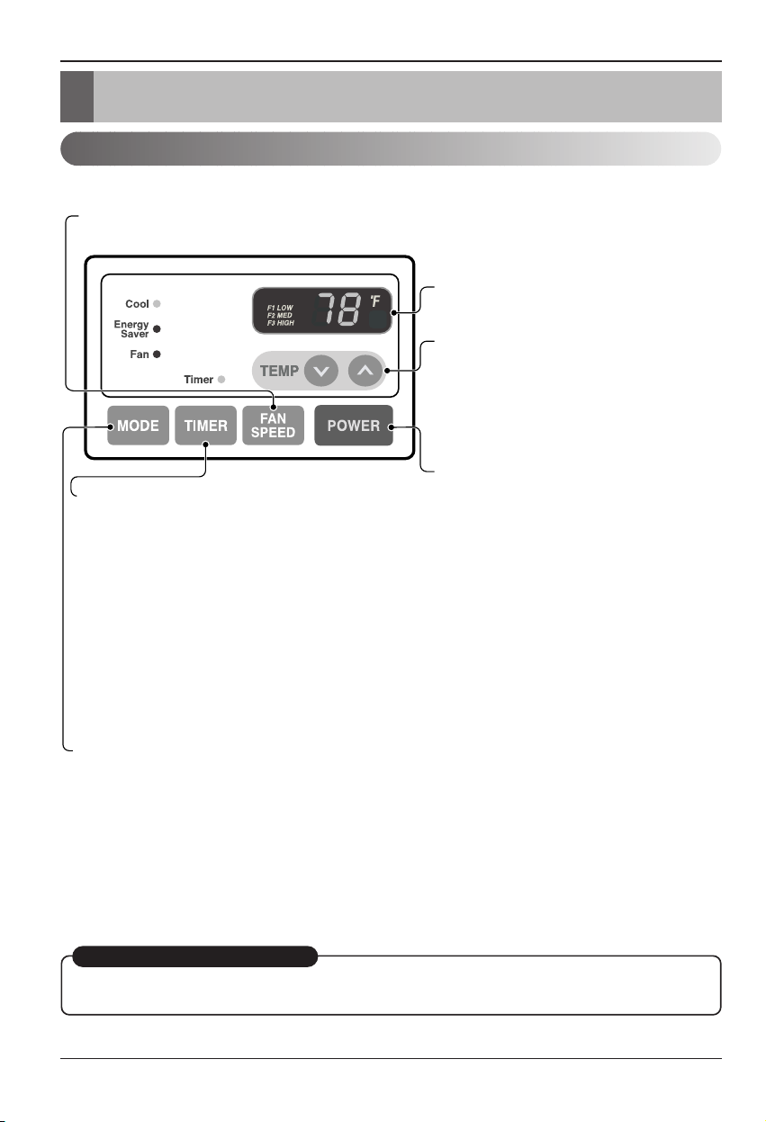
18 Aire Acondicionador
Instruccionnes de Funcionamiento
Instruccionnes de Funcionamiento
Controles
La apariencia de los controles será como uno de los siguientes.
RECEPTOR DE SEÑAL DEL MANDO
A DISTANCIA
ENERGÍA
MODO
- Presione este botón para cambiar el modo de funcionamiento de COOL
→ ENERGY SAVER → FAN.
- COOL (fr
ío):
• El ventilador funciona continuamente en enfriamiento normal.
- ENERGY SABER (ahorro de energía):
• El ventilador para su funcionamiento cuando el compresor cesa de enfriar. El ventilador se encenderá y la unidad
comprobará la temperatura del aire de la habitación aproximadamente cada 3 minutos para determinar si es
necesario seguir enfriando.
- FAN (ventilador):
• Sólo está en funcionamiento el ventilador.
TEMPORIZADOR
- HORA DE APAGADO
• Normalmente utilizará el tiempo de apagado mientras usted
duerme.
• Si la unidad está funcionando, utilice el temporizador para
fijar el número de horas hasta que se apague.
• Para su tranquilidad al dormir, una vez que el temporizador
esté configurado, el control de temperatura se elevará hasta
los 2° F tras 30 minutos y de nuevo tras otros 30 minutos.
• Presione el botón del temporizador para avanzar el ajuste de
1 hora → 2 horas → … → 12 horas máximo.
- HORA DE INICIO
• Si la unidad está apagada, utilice el temporizador para establecer el número de horas antes de iniciar la unidad.
• Presione el botón del temporizador para adelantar el ajuste de 1 hora → 2 horas → … → 12 horas máximo.
AJUSTE DE TEMPERATURA
• Utilice este botón para controlar
automáticamente la temperatura del
cuarto. La temperatura puede establecerse
dentro de una gama de 60° F a 86° F
mediante incrementos de 1° F.
• El ajuste se muestra en pantalla.
• Para ENCENDER el aire acondicionado,
presione este botón. Para APAGAR el aire
acondicionado, presione de nuevo el
botón.
• Este botón tiene prioridad sobre cualquier
otro botón.
• Cuando la encienda por primera vez, la
unidad estará en modo frío, alta velocidad
del ventilador, control de temperatura en
72° F.
VELOCIDAD DEL VENTILADOR
• Cada vez que presione este botón, el ajuste cambiará como sigue a continuación: {Alto → Bajo → Medio → Alto}
REINICIO AUTOMÁTICO
Cuando se restablezca la alimentación después de un corte en el suministro, la unidad empezará a
funcionar con su último ajuste.
Page 67

Manual del Propietario 19
ESPAÑOL
Instruccionnes de Funcionamiento
Control remoto
El mando a distancia y el panel de control se parecerán a los de las siguientes imágenes.
Power
Temp
Fan Speed
Timer Mode
ENERGÍA
• Presione este botón para ENCENDER el aire acondicionado.
Para APAGAR el aire acondicionado vuelva a presionar el botón.
• Este botón tiene prioridad sobre cualquier otro botón.
• Al encenderla por primera vez, la unidad se encuentra en modo frío, alta
velocidad del ventilador, ajuste de temperatura a 72° F.
• Reinicio automático
En el caso de una caída de tensión, la unidad funcionará bajo la configuración
anterior una vez que la tensión vuelva a ser la normal.
AJUSTE DE TEMPERATURA
• Utilice este botón para controlar automáticamente la temperatura del cuarto.
La temperatura puede establecerse dentro de una gama de 60° F a 86° F por
incrementos de 1° F.
• El ajuste aparece en pantalla.
VELOCIDAD DEL VENTILADOR
• Cada vez que presione este botón, el ajuste cambiará como sigue a
continuación: {Alto → Bajo → Medio → Alto}
MODO
- Presione este botón para cambiar el modo de funcionamiento de COOL
→
ENERGY SAVER
→
FAN.
- COOL (frío):
• El ventilador funciona continuamente en enfriamiento normal.
- ENERGY SABER (ahorro de energía):
• El ventilador para su funcionamiento cuando el compresor cesa de enfriar. El ventilador se encenderá y la
unidad comprobará la temperatura del aire de la habitación aproximadamente cada 3 minutos para determinar si
es necesario seguir enfriando.
- FAN (ventilador):
• Sólo está en funcionamiento el ventilador.
TEMPORIZADOR
- HORA DE APAGADO
• Normalmente utilizará el tiempo de apagado mientras usted duerme.
• Si la unidad está funcionando, utilice el temporizador para fijar el número de
horas hasta que se apague.
• Para su tranquilidad al dormir, una vez que el temporizador esté
configurado, el control de temperatura se elevará hasta los 2° F tras 30
minutos y de nuevo tras otros 30 minutos.
• Presione el botón del temporizador para avanzar el ajuste de 1 hora → 2
horas → … → 12 horas máximo.
- HORA DE INICIO
• Si la unidad está apagada, utilice el temporizador para establecer el número
de horas antes de iniciar la unidad.
• Presione el botón del temporizador para adelantar el ajuste de 1 hora → 2
horas → … → 12 horas máximo.
Page 68

20 Aire Acondicionador
Instruccionnes de Funcionamiento
Cómo Poner Las Baterias
1. Quite la tapa de la parte posterior del
telemando. Para ello haga deslizar la tapa
según la dirección del la flecha.
2. Introduzca las dos baterías, asegurándose de
que las direcciones (+) y (-) estén colocadas
correctament. Use baterías nuevas.
3. Volver a cerrar, resbalando la tapa hasta la
posición inicial.
• No utilice baterís recargables,
éstas son diferentes de forma,
de dimensiónyusorespectoa
las baterías secas usuales.
• Seque las baterías del
telemando cuando el
acondicionador no vaya a ser
usado durante un largo
período.
PULL OPEN / PUSH CLOSE
Ventilación
Dirección del aire
La palanca de ventilaciónestá colocada en el extremo derecho de
la descarga de aire.
Esta palanca debe estar en la posición CLOSE (Cerrada) a fin de
mantener las mejores condiciones de enfriamiento.
Cuando se necesita aire fresco en la habitación, coloque la palanca
de ventilaciónenlaposición OPEN (abierta).
El regulador de tiro está abierto y el aire de la habitaciónes
expulsado hacia el exterior.
El aire puede dirigirse hacia donde usted desee ajustando las rejillas horizontales y verticales.
•
CONTROL HORIZONTAL DE LA
DIRECCIÓN DEL AIRE
La dirección horizontal del aire se ajusta moviendo la
rejilla vertical.
La palanca de la rejilla vertical está situada a los
costados derecho e izquierdo de la descarga de aire.
•
CONTROL VERTICAL DE LA DIRECCIÓN
DEL AIRE
La dirección vertical del aire se ajusta moviendo la
rejilla horizontal.
Page 69

Manual del Propietario 21
ESPAÑOL
Cuidado y Mantenimiento
Cuidado y Mantenimiento
Limpieza del filtro de aire
Como agregar la rejilla frontal al gabinete
APAGUE EL ACONDICIONADOR DE AIRE Y DESENCHÚFELO DE LA FUENTE DE PODER.
El filtro de aire debe ser controlado al menos dos veces al mes para ver si es necesaria su
limpieza.
Las partículas atrapadas en el filtro pueden acumularse y
bloquear el flujo del aire. Esto reduce la capacidad de
refrigeraciónytambién causa una acumulacióndehielo
en los sepentines de enfriamiento.
Si el filtro se inutiliza o se daña, debe ser reemplazado
inmediatamente. Filtros de repuesto están disponibles en la
tienda donde lo compró, el representante y en los centros de
servicios autorizados.
1. Abra la rejilla de entrada hacia abajo tirando de la parte
superior de la rejilla de entrada.
2. Quite el filtro de aire de la rejilla frontal tirando ligeramente
del filtro de aire.
3. Lave el filtro usando agua tibia por debajo de 40°C
(104°F).
4. Sacuda suavemente el exceso de agua del filtro.
Reemplace el filtro.
La rejilla frontal puede quitarse para su limpieza o para comprobar el modelo y el número de
serie.
Para su seguridad, debe seguir el siguiente procedimiento para colocarla.
1. Quite la parte superior de la rejilla frontal de
la parte superior del gabinete.
2. Empuje los extremos frontales de la rejilla
hacia el gabinete a fin de insertar las
pestañas de la rejilla frontal en el gabinete.
3. Abra la rejilla de entrada.
4. Ajuste los tornillos a través de la rejilla frontal
en la placa de la caja de control.
5. Cierre la rejilla de entrada.
Page 70

22 Aire Acondicionador
Cuidado y Mantenimiento
Problemas y soluciones habituales
Operación normal
Operación anormal
Las sugerencias para solucionar problemas ahorran tiempo y dinero !
Revise la cartilla de más abajo antes de llamar al service, tal vez no tenga que hacerlo.
• Se puede oír un ruido agudo causado por el agua cuando está siendo recogida y arrojada contra el
condensador en días lluviosos o cuando la humedad es alta. Esta característica de diseñoayudaaquitarla
humedad y mejorar la eficiencia.
• Se pueden oír clicks en el termostato cuando el compresor gira hacia dentro y hacia afuera.
• El agua se depositará en la bandeja de base durante los días lluviosos o de humedad alta.
El agua puede rebalsar y gotear desde el lado exterior de la unidad.
• El ventilador puede funcionar aún cuando el compresor no lo hace.
Probama Causas posibles Que hacer
■ El acondicionador de aire
está desenchufado.
■ El fusible está quemado/el
interruptor de circuito está
abierto.
■ Interrupción de la provisión
de energía eléctrica.
■ El dispositivo interruptor de
corriente está
desconectado.
■ Elflujodeaireestá
restringido
■ Coloque el control de
TEMPERATURA en un
número más alto.
■ El filtro de aire está sucio.
■ La habitación puede haber
estado caliente.
■ El aire frío se escapa.
■ Los serpentines de
enfriamiento se han
congelado.
■ El hielo bloquea el flujo de
aire y no permite que el
acondicionador de aire
enfríe la habitación.
• Asegúrese de que el enchufe del acondicionador de aire
sea totalmente ajustado dentro de la salida.
• Compruebe el fusible de la casa /la caja del interruptor
de circuito y reemplace el fusible o vuelva a colocar el
interruptor.
• Si se produce una interrupcióndelaprovisiónde
energíaeléctrica, gire el control a OFF (apagado).
Cuando la energía se restituye, espere 3 minutos para
reiniciar el acondicionador de aire para prevenir que el
compresor se dispare.
• Presione el botón RESET situado en el enchufe del
cable de alimentación. Si el botón RESET no
permanece activo, suspenda el uso del aire
acondicionado y póngase en contacto con un técnico de
servicio cualificado.
• Asegúresedequenohayacortinas,persianas,o
muebles que bloqueen la parte frontal del
acondicionador de aire.
• Gire el control de TEMPERATURA a un número más
bajo.
• Limpie el filtro por lo menos cada 2 semanas. Vea la
sección de instrucciones para el funcionamiento.
•
Cuando el acondicionador de aire se ha encendido por primera
vez, se necesita tiempo para que la habitaciónseenfríe.
• Compruebe si las rejillas del respiradero del piso están
abiertas y que el aire frío regrese.
• Coloque el respiradero del acondicionador de aire en
posicióncerrada.
• Vea m ás abajo "Congelamiento del acondicionador
de aire".
• Ajustar el control de mode en 'VentilaciónAlta'o
'ErfriamientoAlto'conlatemperaturaalta.
El acondicionador
de aire no arranca.
El acondicionador
de aire no enfría
como debería.
Congelamiento del
acondicionador de
aire
Page 71

Manual del Propietario 23
ESPAÑOL
ParamodelosinstaladosfueradeAmérica del Norte: para aires acondicionados adquiridos para el uso
fuera de América del Norte, el fabricante no extiende ninguna garantíaimplícita o expresa. Consulte a su
distribuidor sobre las condiciones de garantía extendida por el importador en su país.
Si ha leído completamente el folleto de instrucciones e instalación y necesita asistencia técnica llame al
1-877-755-7932
o escriba a:
Heat Controller Inc.
1900 Wellworth Ave. Jackson, MI 49203
Prueba de fecha de compra
Es responsabilidad del usuario establecer la fecha de compra original a efectos de garantía. Recomendamos
que guarde una factura de venta, un cheque anulado o cualquier otro registro de pago apropiado para este
propósito.
Si tiene más dudas, llame al 1-517-787-2100
O escriba un mensaje de correo electrónico a techservice@heatcontroller.com
Llame al (517) 787-2100 para obtener piezas de recambio fuera de su periodo de garantía.
Page 72

Specifications and performance data subject to change without notice.
HEAT CONTROLLER, INC.
1900 WELLWORTH AVENUE • JACKSON, MICHIGAN 49203
THE QUALITY LEADER IN CONDITIONING AIR
P/No.: 3828A21015R
 Loading...