

Page 1
HTGR32-4 HTGR40-5
__________________________________
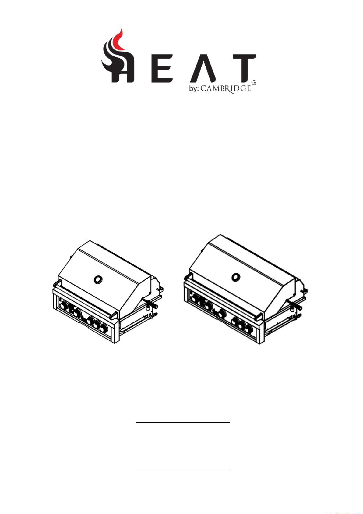
Use & Care Guide
For Liquid Propane and Natural Gas Grills
Models: HTGR32-4 (NG/LP) and HTGR40-5 (NG/LP)
For Outdoor Use Only
-CONTACT INFORMATION-
HEAT Outdoor Living P.O. BOX 16262, Philadelphia PA 19114
866-876-9959 or CustomerService@Heat-OutdoorLiving.com
www.Heat-OutdoorLiving.com
Version 1.0
Page 2

CAUTION
Indicates a potentially hazardous situation which, if not avoided, may result in minor or
moderate personal injury, or property damage.
WARNING
Indicates a potentially hazardous situation which, if not avoided, could result in death or serious
injury.
Congratulations on the purchase of your new HEAT Grill. With proper care your grill
will give many years of reliable cooking!
IMPORTANT:
INSTALLER: Please leave these instructions with the consumer.
CONSUMER: Please read this manual carefully and before using your HEAT grill to ensure
proper operation, installation, servicing and to reduce the risk of fire, burn hazard and or other
injury. This manual should be retained for your information.
NOTE:
All gas installations and gas conversions must be performed by a qualified technician or
authorized service agent.
Improper installation and service or maintenance may cause property damage, injury or death.
Do not operate this appliance without having read this manual.
NOTE:
This appliance is not intended for commercial use.
DANGER:
IF YOU SMELL GAS:
1) Shut off the gas supply to the appliance at its source.
2) Extinguish any open flames.
3) Open grill hood to release any accumulation of gas vapor.
4) If a gas odor persists, keep away from your appliance and contact your gas supplier or
fire department immediately.
WARNING:
1) Do not store or use gasoline or other flammable liquids or vapor in the vicinity of this or
any other appliance.
2) An LP cylinder not connected for use shall not be stored in the vicinity of this or any other
appliance.
NOTE:
The manufacturer cannot be held responsible for damage or injury caused by improper use of
this appliance.
Page | 2
Page 3

Table of Contents
Safety Instructions 4-5
Grill Models 6
Gas Requirements 7-10
Installing the Grill 11-13
Pre-Operation Leak Testing 14
Lighting the Grill 15
Operation and Features 16-19
Care and Maintenance 20-21
Troubleshooting Your Grill 22-23
Parts List and Breakdowns 24-27
HEAT Product Registration 28-29
Warranty 31
Page | 3
Page 4

Safety Instructions
WARNING: Improper installation, adjustment, alteration, service or maintenance can cause injury or
property damage. Read the installation, operating and maintenance instructions thoroughly before
installing or servicing this equipment.
General Safety Instructions
1. For Household Outdoor Use Only – DO NOT use indoors or in any type of enclosed area such as a
garage, shed or breezeway. Keep clear of trees and shrubs. The grills are not intended for
installation in or on recreational vehicles, portable trailers, boats or any other moving installation.
Not for commercial use.
2. The area surrounding your new grill should be kept clean and free from flammable liquids and other
combustible materials such as mops, rags or brooms, as well as solvents, cleaning fluids, and
gasoline.
3. To reduce the risk of serious or fatal injury from breathing toxic fumes and from explosion and fire
as a result of leaking gas, use only outdoors in an open area with good ventilation. Do not obstruct
the flow of combustion and ventilation air.
4. Never use the grill in windy conditions. If located in a consistently windy area (oceanfront,
mountaintop, etc.) a wind break will be required. Always adhere to the specified clearances listed.
5. Do not leave the grill unattended while cooking.
6. Do not use natural gas in a unit designed for liquid propane gas or vice versa.
7. Do not use fuel such as charcoal briquettes in a gas grill.
8. Keep children and pets away from hot grill. DO NOT allow children to use or play near the grill.
9. Never attempt to repair or replace any part of the grill yourself unless specifically recommended in
this manual. All other services should be performed by a qualified service technician.
10. Never lean over an open grill. Do not place clothing or other flammable material on or near the grill.
Do not wear loose-fitting clothes or long sleeves while using the grill as some fabrics can be highly
flammable.
11. Have an ABC fire extinguisher accessible. Never attempt to extinguish a grease fire with water or
other liquids.
12. When using the grill, do not touch the grill rack, burner grate, or immediate surroundings as these
areas become extremely hot and can cause burns. Always use a covered hand when opening the
grill hood and only do so slowly to allow heat and steam to escape.
13. DO NOT allow grease or other hot material to drip from the grill onto valves, hoses or regulator, turn
off gas supply immediately should this happen. After the grill has cooled, determine the cause and
correct it. After cleaning the valve, hose and regulator, perform a leak test before continuing use.
14. Do not heat any unopened glass or metal container of food on the grill. Pressure may build up and
cause the container to burst, possibly resulting in serious personal injury or damage to the grill.
15. Keep any electrical supply cords away from water or heated surfaces. Electrical cords should be
placed away from walkways to avoid a tripping hazard.
16. Keep gas supply lines as short as possible.
17. Never move the grill when it is hot.
18. DO NOT use the grill while under the influence of drugs or alcohol.
19. DO NOT store a spare gas cylinder under or near your grill.
20. DO NOT grill without the drip tray in place, hot grease could leak downward and produce a fire or
an explosion. Drip tray should be pushed all the way to the rack located just under the grill.
Page | 4
Page 5
5011443
Conforms to
ANSI STD Z21.58-2018
Certified to CSA STD 1.6-2018
Outdoor Cooking Gas Appliance
21. Grease is extremely flammable. Let hot grease cool down before attempting to handle or dispose of
it. The drip tray should be cleaned on a regular basis and kept free of grease build up.
22. In the event that a burner goes out, turn burner knobs to the full OFF position, fully open the grill
hood and let it air out. Do not attempt to use the grill until the gas has had time to dissipate.
23. Do not use the grill until leak check has been made.
24. Turn off the cylinder valve when your grill is not in use.
25. Ensure the control knobs are in the “OFF” position when not in use.
26. Use only a Ground Fault Interrupter (GFI) protected circuit with this outdoor cooking gas appliance.
CALIFORNIA PROPOSITION 65 WARNING
The burning of gas cooking fuels generates some byproducts which are on the list of substances which
are known by the State of California to cause cancer or reproductive harm. California law requires
businesses to warn customers of potential exposure to such substances. To minimize exposure to
these substances, always operate this unit according to the Use and Care Manual, ensuring you
provide good ventilation when cooking with gas.
Page | 5
Page 6
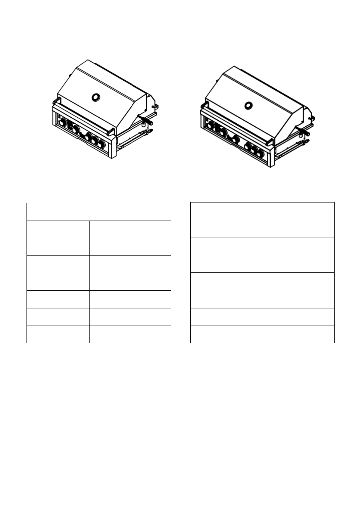
Model: HTGR-32-LP & HTGR-32-NG
Dimensions
32-3/8”W x 25-5/8”D x 21”H
BTU Output
11,000 BTU per burner X4
Infrared Back Burner
14,000 BTU
Total BTU
58,000
Rotisserie Kit
Optional
Burner
Cast Stainless Steel
Warranty
See warranty section for details
Model: HTGR-40-LP & HTGR-40-NG
Dimensions
40-3/8W x 25-5/8”D x 21”H
BTU Output
11,000 BTU per burner X5
Infrared Back Burner
14,000 BTU
Total BTU
69,000
Rotisserie Kit
Optional
Burner
Cast Stainless Steel
Warranty
See warranty section for details
Grill Models
Page | 6
Page 7
LP Gas Hook-up
Gas Connections
NOTE: Always have a qualified service technician perform difficult conversions or modifications.
WARNING: Never attach an unregulated gas line to the appliance. Connection to an
unregulated gas line can cause excessive heat or fire.
IMPORTANT: Before connecting grill to gas source, make sure control knobs are in “OFF” position.
Verify the type of gas supply to be used, either Natural Gas or LP (Propane), and make sure the
marking on the appliance rating label agrees with that of the supply.
All pipe sealants must be an approved type and resistant to the actions of LP gas. Never use pipe
sealant on flare fittings. The installation of this appliance must conform with local codes or, in the
absence of local codes, with either National Fuel Gas Code, ANSI Z223.1/ NFPA 54, Natural Gas and
Propane Installation Code, CSA B149.1, or Propane Storage and Handling Code, B149.2, or the
Standard for Recreational Vehicles, ANSI A 119.2/ NFPA 1192M, and CSA Z240 RV Series,
Recreational Vehicle Code, as applicable.
WARNING: Gas valves are preset at the factory to operate on LP or natural gas. If you wish to convert,
be sure to contact your grill dealer FIRST!
This propane gas grill is designed to operate on propane gas ONLY, at a pressure regulated at 11”
water column (W.C.) when equipped with the correct propane orifices on the valves and a propane
regulator on the supply line regulated at the residential meter. The LP gas grill is designed to be used
with a standard 20 lbs. gas cylinder that must be constructed and marked in accordance with
specifications of the US Department of Transportation for propane gas cylinders.
Always keep cylinder securely fastened in an upright position. Never connect an unregulated propane
gas cylinder to the grill.
Do not subject propane cylinders to excessive heat.
CAUTION: Never store a LP gas cylinder inside a building or in the vicinity of any gas-burning
appliance.
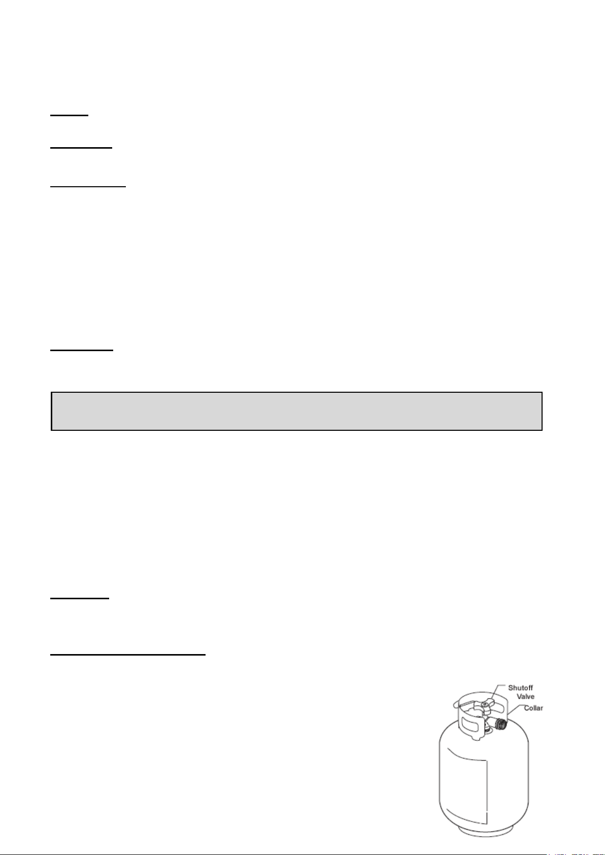
Cylinder Specifications
- Any LP gas supply cylinder used with this grill must be approximately 12 inches diameter and 18
inches high. The maximum fuel capacity is 80% and is approximately
20 pounds of propane.
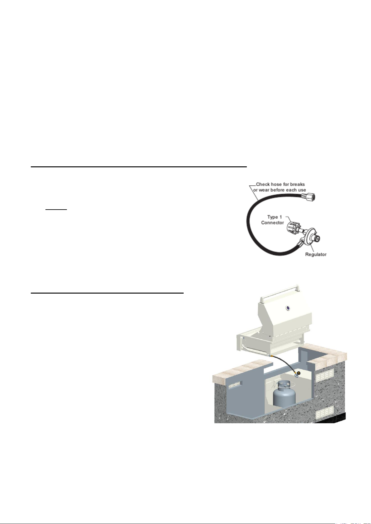
- The LP cylinder must have a shut-off valve (see picture) terminating in
a Type 1 LP.
- A Type 1 compatible cylinder with a Type 1 cylinder valve has a
back-check valve which does not permit gas flow, until a positive seal
has been obtained.
Page | 7
Page 8
- The cylinder must be arranged for vapor withdrawal. It must also include a collar to protect the
cylinder valve. A safety relief device having direct communication with the vapor space of cylinder
must be provided. This will expel high pressure gas if the cylinder is overfilled or overheated which
could result in fire or explosion.
- All LP gas cylinders used with this appliance shall be constructed and marked in accordance with
the specifications for LP gas cylinders of the U. S. Department of Transportation (DOT) or the
National Standard of Canada, CAN/CSA-B339, Cylinders, Spheres and Tubes for Transportation of
Dangerous Goods; and Commission, as applicable; and shall be provided with a listed overfilling
prevention device.
- Read labels on the LP gas supply cylinder.
- Allow only qualified LP gas dealers to fill or repair your LP gas supply cylinder.
- After filling, have the gas dealer check for leaks and to see that the relief valve remains free to
function.
Hose and Regulator (included standard with the grill)
The Type 1 connection system has the following features:
- The system will not allow gas to flow until a positive connection
has been made.
NOTE: The cylinder control valve must be turned off
before any connection is made or removed.
- The system has a thermal element that will shut off the flow of
gas in the event of a fire.
- The system has a flow limiting device which, when activated,
will limit the flow of gas to 10 cubic feet per hour.
- NEVER use grill without leak testing this connection.
LP (Propane) Gas Supply Connection
1. The tank valve should be in the “OFF” position. If
not, turn the knob clockwise until it stops.
2. Make sure all burner valves are in the “OFF”
position.
3. Always connect the gas supply regulator as
follows:
Insert the regulator inlet into the tank valve and turn
the coupling nut clockwise until the coupler tightens
up (see picture). Do not over tighten the coupler.
Turn the main tank valve on and turn the burner
control valves on the unit to the “HIGH” position for
about 20 seconds to allow the air in the system to
purge before attempting to light the burners.
Page | 8
Page 9
WARNING: Always take a leak test before lighting the grill to prevent a possible fire or explosion.
Never store a spare propane cylinder in the vicinity of this grill, or in the vicinity of any other potential
heat source.
LP (Propane) Gas Supply Cylinder Disconnection
1. Turn the burner valves off.
2. Turn the tank valve off. (Turn clockwise to stop.)
3. Detach the regulator assembly from the tank valve by turning the quick coupling nut
counterclockwise.
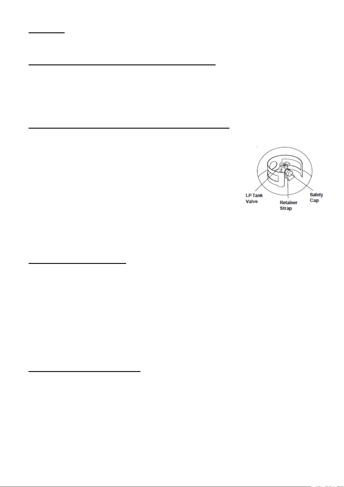
LP (Propane) Tank Removal, Transport, and Storage
- Turn OFF all control knobs and LP tank valve. Turn coupling nut counterclockwise by hand only do not use tools to disconnect. Lift LP tank wire upward off of LP
tank collar, then lift LP tank up and off of support bracket. Install
safety cap onto LP tank valve. Always use cap and strap supplied
with valve. Failure to use safety cap as directed may result in
serious personal injury and/or property damage.
- A disconnected LP tank in storage or being transported must have a
safety cap installed (as shown). Do not store an LP tank in
enclosed spaces such as a carport, garage, porch, covered patio or
other building. Never leave a LP tank inside a vehicle which may
become overheated by the sun.
- Do not store LP tank in an area where children play.
LP (Propane) Tank Filling
- Use only licensed and experienced dealers.
- LP dealer must purged tank before filling.
- Dealer should NEVER fill LP tank more than 80% of LP tank volume. Volume of propane in tank will
vary by temperature.
- A frosty regulator indicates gas overfill. Immediately close LP tank valve and call local LP gas
dealer for assistance.
- Do not release liquid propane (LP) gas into the atmosphere. This is a hazardous practice.
- To remove gas from LP tank, contact an LP dealer or call a local fire department for assistance.
Check the telephone directory under “gas companies” for nearest certified LP dealers.
LP (Propane) Tank Exchange
- Exchange your Type 1 cylinder with OPD safety feature-equipped ONLY.
- Always keep new and exchanged LP tanks in upright position during use, transit or storage.
- Leak test new and exchanged LP tanks BEFORE connecting to grill.
Page | 9
Page 10
Natural Gas Hook-up
-
Always check the rating plate to make sure the gas supply you are hooking up to is the gas type the grill
is manufactured for.
This natural gas grill is designed to operate on natural gas ONLY, at a pressure regulated at 4” water
column (W.C.) when equipped with the correct natural gas orifices on the valves and a natural gas
regulator on the supply line regulated at the residential meter.
NOTE: Supply line must be ½” ID from gas supply to regulator.
We recommend consulting a local licensed plumber to insure proper gas volume.
IMPORTANT: Never connect the grill to an unregulated gas supply.
Natural gas connections must be performed by a licensed contractor or local gas company
representative.
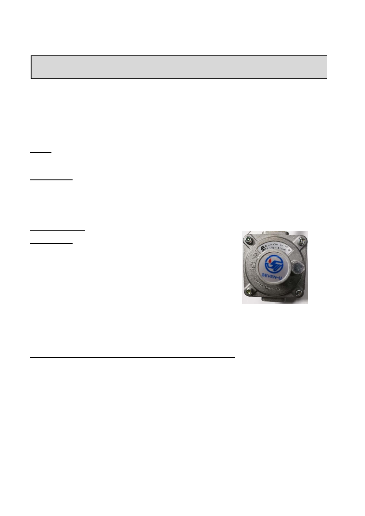
NG Regulator
IMPORTANT: NEVER use grill without leak testing this connection.
Natural gas regulator model: GR120N
Gas pressure: 4”
Maximum rate working pressure: 1/2 PSIG
Natural Gas Supply Connection and Disconnection
1. Make sure all burner valves are in the “OFF” position.
2. To connect-push back sleeve of socket, insert plug release sleeve. Push plug until sleeve snaps
forward locking plug into socket. (THIS AUTOMATICALLY TURNS ON GAS.)
3. To disconnect: Push sleeve back and pull out plug. (THIS AUTOMATICALLY SHUTS OFF GAS.)
4. Connected hose assembly shall be of adequate length and capacity for intended application. Final
assembly must be tested for leaks.
Page | 10
Page 11

HEIGHT
MODEL
WIDTH
DEPTH
HEIGHT
HTGR32-4
30-5/8”
21-1/4”
8-1/2”
HTGR40-5
38-5/8”
21-1/4”
8-1/2”
HTA-INSJACK-4B
33”
22-1/4”
9-5/8”
HTA-INSJACK-5B
40-3/4”
22-1/4”
9-5/8”
WIDTH
DEPTH
Grill Island Cut-Out Dimensions
Page | 11
Page 12

- The island must be built out of non-combustible material. In the event it is
combustible, the use of the insulation jacket is required.
- 4-Burner Model # HTA-INSJACK-4B
- 5-Burner Model # HTA-INSJACK-5B
- Protection from weather: Keep the grill protected from adverse weather,
including rain and wind. Wind, particularly coming into the rear of the grill, can
affect the exhaust from escaping from the grill. This can back up the heat behind
the control panel potentially creating a gas leak, damage to the product, and injury.
A wind block behind the grill may be necessary.
- A distance of 12” will be needed behind the frill for the lid to open and close.
Remember that should combustible materials (such as a combustible wall) be
located behind the grill that the needed 12” for the lid clearance does not satisfy
the distance required from a combustible surface.
- At least two vents are required for every island.
Failure to adequately vent your outdoor kitchen cavity could
result in an explosion or fire.
LP/Propane Gas: LP gas is heavier than air and will settle to the lowest levels of the outdoor kitchen. It
is imperative to provide adequate cross ventilation for the areas where gas can accumulate at these
lower levels of the island cavity. Should the Propane cylinder be located in the outdoor kitchen itself, a
plenum wall is required to separate the gas source from the other areas of the outdoor kitchen (picture
shown in owner’s manual), and both the cabinets containing the gas appliances and the gas tank
should be ventilated appropriately. If a plenum wall is undesirable, HEAT offers a Propane tank drawer
as an alternative.
NG/Natural Gas: Natural gas is lighter than air and will rise to the highest levels of the outdoor kitchen.
It is imperative to provide adequate cross ventilation for the areas where gas can accumulate at these
higher levels of the island cavity.
Page | 12
Page 13

Installing the Grill in a BBQ Island
NOTE: Check with City and Fire department for Local Building Codes. A Permit may be
required for outdoor kitchen construction.
Check your local building codes for the proper method of installation. In the absence of
local codes, this unit should be installed in accordance with the National Fuel Gas Code No.
Z223.1-1998 USA or CAN/CGA-B149.1/.2 Natural Gas/Propane Code (Canada) latest edition
or the National Electrical Code ANSI/NFPA No. 70 or the Canadian Electrical Code CSA
C22.1, 1990 or latest version.
- Before installing built-in grills in enclosures, copy all product information such as model number,
serial number, and type of gas (e.g. natural gas or propane) and store information in a safe place.
- If the grill is installed by a professional installer or technician, be sure that they show you where
your gas supply shut-off is located. All gas lines must have a shut-off that is readily and easily
accessible. If you smell gas, check for gas leaks immediately. Check only with a soap and water
solution. Never check for gas leaks with an open flame.
NOTICE: We strongly recommend professional installation and hookup of the Gas BBQ grill. These
instructions will provide you with the measurements necessary for you or your builder to construct a
masonry structure to house your outdoor gas grill.
IMPORTANT: Gas fittings, regulator, and installer supplied shut-off valves must be easily accessible.
Locate the grill only in a well ventilated area. Never locate the grill in a building, garage, breezeway,
shed, or other such enclosed areas without an approved ventilation system. During heavy use, the grill
will produce a lot of smoke. Ensure there is adequate area for it to dissipate.
Required Clearance
- CLEARANCE FOR NON-COMBUSTIBLE CONSTRUCTION: 12" clearance from the back of the
grill is needed for the purpose of opening the hood fully. It is desirable to allow at least 4" side
clearance to non-combustible construction above the cooking surface for counter space. If you
wish to use the rotisserie option, the space is essential for motor and rotisserie clearance. The grill
can be placed directly adjacent to non-combustible construction below the cooking surface. The
grill exhausts combustion products and cooking greases to the back. Never locate the grill where
this exhaust will be difficult to clean.
- CLEARANCE TO COMBUSTIBLE CONSTRUCTION: A Minimum of 24" from the sides and a
minimum of 24" from the back must be maintained from the grill above and below the cooking
surface to adjacent vertical combustible construction.
For Built-in Installations
A built-in grill is designed for easy installation into masonry enclosures. For non-combustible
applications, the grill drops into the opening (as shown in grill island cut-out dimensions) above or
below depending on space, and hangs from its counter top trim. It is recommended that the enclosure
have ventilation holes to prevent gas build-up in the event of a leak. The deck ledges and counter
should be flat and level in reference to the floor. If your grill is equipped with an optional rotisserie,
electrical service should be provided. If your grill is equipped with an optional rotisserie, a minimum of
24" of clearance is needed on each side of the grill for the motor and rotisserie.
Page | 13
Page 14

Keep any electrical supply cords and the fuel supply hose away from any
heated surfaces.
Pre-Operation Leak Test
DANGER:
1. Do not insert any tool into the valve outlet or safety relief valve. You may damage the valve and
cause a leak. Leaking propane may result in explosion, fire, severe personal injury, or death.
2. If a leak is detected at any time or you cannot stop a gas leak, immediately close pipeline valve and
call an LP gas supplier or your fire department.
3. Check all gas supply fittings before each use and each time the gas supply cylinder is connected to
the regulator. Have a qualified service technician leak test the grill any time a part of the gas system
is replaced.
WARNING:
Never attempt to attach this grill to the self-contained LP gas system. Do not use the grill until leak
testing.
Before Testing
DO NOT smoke while leak testing. Extinguish all open flames. Never leak test with an open flame. Mix
a solution of equal parts mild detergent or liquid soap and water.
Leak Testing Valves, Hose and Regulator
1. Turn all grill control knobs to OFF.
2. Be sure hose is tightly connected to LP tank.
3. Completely open LP tank valve by turning cylinder valve
knob counterclockwise (right to left). If you hear a rushing
sound, turn gas off immediately. There is a major leak at the
connection. Correct before proceeding by calling franchiser
for replacement parts.
4. Brush soapy solution onto areas where bubbles are
shown in LP tank (see picture).
5. If “growing” bubbles appear, there is a leak. Close LP
tank valve immediately and retighten connections. If leads
cannot be stopped do not try to repair. Call franchiser for replacement.
6. Always close LP tank valve after performing leak test by turning cylinder valve knob clockwise.
NOTE: When leak testing this appliance, make sure to test and tighten all loose connections, including
the side burner. A slight leak in the system can result in a low flame, or a hazardous condition.
Page | 14
Page 15

WARNING:
DO NOT use the grill if gas odor is present.
DO NOT stand with head, body, or arms over the grill when lighting.
Inspect the hose before using the grill. If there is excessive abrasion or wear, or if the hose is cut, it must be replaced prior
to the outdoor cooking gas appliance being put into operation. The replacement hose assembly shall be that specified by
the manufacturer.
Ensure the area around the barbecue is clear of flammable substances such as gasoline, yard debris, wood, etc.
Ensure there is no blockage of the airflow through the vent space located below the face of the unit.
DANGER:
Failure to open the lid while igniting the barbecue’s burners, or not waiting 5 minutes to allow the gas to clear if the
barbecue does not light before retrying may result in an explosive flame-up which can cause serious bodily injury or death.
GENERAL RULES
Lighting the Grill
Do not leave the grill unattended while cooking!
- Make sure the grill has been leak tested and is properly located.
- Check the end of each burner tube is properly located over each valve orifice.
- Light the grill burners using the instructions provided in this manual.
- Adjust heat settings to your desired cooking temperature.
- Allow grill to cool down, wipe off any splatters or grease and clean the drip tray as needed.
- Do not put a cover on the grill while it is still hot as it could start a fire.
NOTE: If for some reason, the grill fails to light, burners can be lit with a gas lighter.
NOTE: To light gas grill with a gas lighter, make sure the grill
has been leak tested and burners are properly located. Remove
the cooking grids and flame tamers from the burner you wish to
light. Insert a long-necked gas lighter, placing it near to burner
ports. Press in the last right control knob and rotate left to “HIGH”
setting to release gas. Turn on the button on gas lighter, burner
should light immediately. Place back the cooking grids and flame
tamers. Adjust burners to desired cooking temperature.
Lighting Instructions
1. Open Lid.
2. Ensuring controls knobs are in “off” position; turn on the gas supply valve.
3. Press and turn the last Right knob to HIGH position 3-5 seconds to light burner.
4. If ignition does not occur in 5 seconds, turn the control knob to “OFF”, wait 5 minutes to allow gas to
dissipate and repeat the lighting process.
5. To light the other SUS burners, press and turn control knob one by one counterclockwise to HIGH
position and adjust to desired cooking temperature.
6. Press and turn the rear burner knob to HIGH position 3-5 seconds to light the rear burner.
7. If ignition does not occur in 5 seconds, turn the back burner control knob to “OFF”, wait 5 minutes to
allow gas to dissipate and repeat the lighting process.
8. Adjust the back burner control knob counterclockwise to desired cooking temperature.
Page | 15
Page 16

WARNING: To prevent possible bodily injury never stand with your head directly over the grill
when preparing to light the rotisseries burner.
Operations and Features
When initially lighting your grill for cooking, burn the grill to get rid of any odors or debris by
operating at “HIGH” setting with hood closed for no more than 5 minutes.
Since this is a high temperature grill, closing the hood will cause heat to build up and any
excessive flare-ups will cause internal damage to the grill (knobs, wires, etc.)
Instruction for Optional Rotisserie Assembly
The rotisserie is mostly used to cook large pieces of meat and poultry to assure slow, even cooking.
The constant turning provides a self-basting action, making food cooked on a rotisserie exceptionally
moist and juicy. Rotisserie cooking generally requires 1-½ to 4-½ hours of cook time depending on the
size and type of meat being cooked. You can have rotisserie cooking with indirect heat with the infrared
rotisserie burner. Preferred by professional chefs over other methods, the intense heat is ideal for
searing in the natural juices and nutrients found in quality meats.
For successful rotisserie, the meat should be centered and balanced as evenly as possible on the
rotisserie rod to avoid overworking the rotisserie motor.
1. Attach Motor Bracket to the side of the barbecue frame (can be mounted on either left or the right
side of the frame).
2. Insert Rotisserie Motor onto Motor Bracket.
3. Assemble Washer, Balance Weight and Handle to Rotisserie Rod.
4. Slide Prong Forks with the prongs facing away from the handle onto the Rod. Place food on to
the Rod and secure with the second Prong Forks. Secure with thumbscrews. Place Rod assembly
and position into Motor.
5. Once the food is secured, place the sharp end of the Rod onto the motor, and then rest the
Rod on the supports at either side of the grill.
6. Ensure that all bolts are tightened securely.
7. When the rotisserie is being operated exclusively, it is strongly recommended that a pan be
placed on the cooking grids, beneath the food to catch the meat drippings. This will prevent
excessive buildup of drippings on the grids and facilitate cleaning.
Page | 16
Page 17

No.
Description
Qty
1
110V Motor
1
2
Rotisserie Rod
1
3
4-Prong Forks
2
4
Bushing
1
5
Washer
1
6
Balance Weight
1
7
Handle
1 8 Rotisserie Rod Bracket (Rear)
2
WARNING: Never operate Rotisserie Burner with main (other) burner(s) “ON”. Warming Rack
must be removed when Rotisserie Burner is “ON”.
Electrical Grounding Instructions
The rotisserie motor is equipped with a three-prong grounding plug for your protection against electric
shock. This plug must be inserted directly into a properly grounded three-prong receptacle. Do not cut
or remove the grounding prong from this plug.
The rotisserie motor must be electrically grounded in accordance with local codes or, in the absence of
local codes, in accordance with the National Electrical Code, ANSI/NFPA 70-1990 or Canadian
Electrical Code, CSA C22.1.
Do not use an extension cord to supply power to your grill. Such use may result in fire, electrical shock
or other personal injury. Do not install a fuse in the neutral or ground circuit. A fuse in the neutral or
ground circuit may result in an electrical shock hazard. Do not ground this appliance to a gas supply
pipe or hot water pipe.
Preparing Food for the Grill
WARNING: Always observe safe food-handling and safe food-preparation practices when using this
grill, to prevent food-borne illnesses.
- Always cook foods adequately. Undercooked foods can retain bacteria, especially if thawed or
exposed to warm conditions prior to cooking.
- Always use separate plates and utensils for the handling of raw food. Never place raw food and
cooked food on the same plate, and never place cooked food on a plate that was used for handling
raw food.
- Always carefully wash all plates and utensils used to handle raw food before using them to handle
cooked food.
- Always wash all vegetables, seafood and poultry before cooking.
- Always leave uncooked foods in the refrigerator until you are ready to start cooking.
- Always marinate meat in the refrigerator. Dispose of the excess marinade, and never reuse it.
Grilling Tips
- If you pre-cook meat or poultry, do so immediately before grilling.
- Refrigerate leftovers within 2 hours of taking food off the grill.
- Never let the tray boil dry. That could be hazardous, as grease from fatty foods that has collected in
the tray could ignite and possibly cause bodily injury or property damage.
- Use a meat thermometer to be sure food has reached a safe internal temperature.
- Always trim excess fat from your foods to reduce the occurrence of flare-ups during cooking.
- Apply a light coating of cooking oil to the cooking grids before grilling, to prevent foods from
sticking.
- Cook similar portion sizes together, so that they all cook evenly.
- Never pierce foods while they are cooking on the Grill, as this will dry them out.
Page | 17
Page 18

- Apply sugar-based sauces such as commercial barbecue sauces only during the latter stages of
cooking, to prevent charring.
- Soak the string you use to tie up roasts and poultry on the rotisserie spit to protect it from burning.
- Use a disposable aluminum tray filled with water, fruit juice, wine or a marinade to add extra flavor
and moisture to slow-cooked foods like roasts, whole chickens, turkeys or ducks.
Controlling Flare-ups
Flare-ups are a part of cooking meats on a gas grill. This adds to the unique flavor of cooking on a gas
grill. Excessive flare-ups resulting from the build-up of grease in the bottom of the grill can over-cook
the food and cause a dangerous situation for you and your grill. If this should occur, DO NOT pour
water onto the flames, which can cause the grease to splatter and could result in serious burns or bodily
harm. If a grease fire occurs, close the hood and turn off the main burners until the grease burns out.
Use caution when opening the hood as sudden flare-ups may occur.
To Minimize Flare-ups
- Trim excess fat from meats prior to cooking.
- Cook meats with high fat contents (chicken or pork) on low settings or indirectly.
- Ensure that your grill is on level ground and the grease is allowed to evacuate the grill through the
drain hole.
Instruction for Connecting the Transformer
Transformer for Interior and LED Lights
Your transformer will connect on the left side of your grill (looking at it from the front) and operates the
interior and LED lights. Follow the pictures and insert the white male plug into the white female socket,
on the left side of your grill and then plug the transformer into a standard 110V outlet.
Page | 18
Page 19

Instruction for Service
WARNING: Always have a qualified service technician perform difficult conversions or
modifications.
1. Remove the control knobs and drip tray.
2. Unfasten the left and right screws on each knob bezel and remove the 2 screws under the control
panel.
3. Pull the control panel down to open for ease of changing valves or checking the manifold.
Page | 19
Page 20

Care & Maintenance
CAUTION: All cleaning and maintenance should be done only when grill is cool & with the fuel supply
turned off at the cylinder. If your grill is set up for use with natural gas, turn off gas supply at the system
manual shut off valve.
IMPORTANT: Do not leave the grill outside during inclement weather unless it is covered (cover sold
separately). We recommend cleaning and storing the drip tray after every use.
DRIP TRAY
The drip tray located below the grill should be cleaned periodically to prevent heavy buildup of debris.
NOTE: Allow the drip tray to cool before attempting to clean.
COOKING GRATES
The cooking grates can be cleaned immediately after cooking is completed and after turning off the grill.
Wear a barbecue mitt and scrub the cooking grates with a damp cloth. If the grill is allowed to cool down,
cleaning the grates will be easier if removed from the grill and cleaned with a mild detergent.
FLAME TAMERS
Washing the flame tamers after every use is not necessary but periodically it is suggested you wash
them in a soap and warm water solution. Use a wire brush to remove stubborn burned on cooking
residue. Dry the flame tamers thoroughly before you reinstall them in the cooking insert.
BURNERS
IMPORTANT: Gas control knobs should be in the “OFF” position and fuel line should be disconnected.
To reduce the chance of FLASHBACK, the procedure below should be followed at least once a month or
when your grill has not been used for an extended period of time.
1. Remove burners from grill by carefully lifting each burner up and away from gas valve orifice. Wire
brush entire outer surface of burner to remove food debris and dirt. Clean any clogged ports with a stiff
wire such as an open paper clip.
2. Inspect the burner for damage (cracks or holes) and if such damage is found, order and install a new
burner.
3. After installation, check to insure that gas valve orifices are correctly placed inside ends of burner
tubes. Also check position of spark electrode.
STAINLESS STEEL
After initial usage, areas of the grill may discolor from the intense heat given off by the burners. This is
normal. Purchase a mild stainless steel cleaner and rub in the direction of the grain of the metal. Specks
of grease can gather on the surface of the stainless steel and bake on to the surface and give a worn
appearance. For removal, use a non-abrasive oven cleaner in conjunction with a stainless cleaner.
NOTE: Always scrub in the direction of the grain.
Page | 20
Page 21

ANNUAL CLEANING OF GRILL HOUSING
Burning off the barbecue after every cookout will keep it ready for instant use, however, once a year you
should give the entire grill a thorough cleaning to keep it in top operating condition.
1. Shut off gas supply at source and disconnects fuel line. Protect fuel line fitting.
2. Remove and clean the cooking grids, flame tamers and burners.
3. Remove warming rack and wash with mild detergent and warm water.
4. Cover the gas valve orifices with a piece of aluminum foil.
5. Brush the inside and bottom of the grill with a stiff wire brush, and wash down with a mild soap and
warm water solution. Wash thoroughly and let dry.
6. Remove aluminum foil from orifices and check orifices for obstruction.
7. Reinstall flame tamers, cooking grids, and warming rack.
8. Reconnect to gas source and observe burner flame for correct operation.
IMPORTANT: You should NOT line the bottom of the grill housing with aluminum foil, sand or any other
grease absorbent substance. Grease will not be able to drip into the drip tray and a grease fire may
occur.
MAINTENANCE GUIDELINES
1. Keep outdoor cooking gas appliance area clear and free from combustible materials, gasoline
and other flammable vapors and liquids.
2. Do not obstruct the flow of combustion and ventilation air.
3. Keep the ventilation opening(s) of the cylinder enclosure free and clear from debris.
4. Visually check burner flames. Burner flames should be blue and stable with no yellow tips, excessive
noise, or lifting. If any of these conditions exist call our customer service line.
5. Clean outdoor cooking gas appliance, including special surfaces, with recommended cleaning
agents, if necessary.
6. Check and clean burner for insects and insect nests. A clogged tube can lead to a fire beneath the
grill.
WARNING: Make sure each burner if properly replaced after cleaning. It is very important to ensure
the end of the burner is installed appropriately onto the gas valve to ensure gas flows safely into the
burner. Failure to meet these conditions can cause dangerous conditions that can cause personal
injury and/or property damage.
Page | 21
Page 22

Problem:
Possible Causes and Solutions:
Grill will not light
• Is your gas supply turned on?
• If this is an LP (Propane) grill, is there gas in your tank? Check
your gas level.
• Is one of your burners turned on? Allow up to 5 seconds of gas
flow to ignite.
- You should hear a snapping sound when you turn the knob.
Flare-ups
• Check flame tamers and cooking grates for excess food or
grease build-up.
• Ensure grill is not placed directly in the path of wind.
Be sure drip tray is clean (do not use aluminum foil on drip
tray.)
Note: Some flare-ups may be inevitable if cooking greasy
foods.
Yellow Flames
• Check the burner inlet for obstructions, particularly at air inlets
for each burner.
Troubleshooting Your Grill
GENERAL TROUBLE SHOOTING
Inspect the burners at least once a year or immediately if any of the following conditions occur:
• The smell of gas.
• Flames appearing mostly yellow. (Some yellow at the tips is OK.)
• The grill will not get hot enough.
• Burners make a snapping noise.
SPIDER AND INSECT WARNING
Spiders and insects can nest in the burners of this and other grills, which could disrupt
gas flow. This dangerous condition could cause a fire behind and beneath the valve
panel, damaging the grill and making it unsafe to operate. We recommend you check the
grill and remove any spiders, insects and webs at least once a year to reduce this risk.
WHEN TO LOOK FOR SPIDERS
You should inspect the burners once a year or immediately after any of the following conditions occur:
1. The smell of gas in conjunction with the burner flames appearing yellow.
2. The grill does not reach temperature.
3. The burners make popping noises.
BEFORE CALLING FOR SERVICE
If the grill does not function properly, use the chart below before contacting your dealer for service. You
may save yourself the cost of a service call. Troubleshooting is for general purposes only. If the problem
still exists, contact your dealer or the nearest authorized agency for service.
Page | 22
Page 23

• Grill may be in an area that is too windy.
Flame blows out on low setting
or has uneven heat distribution.
• Check for spider webs or insect nest.
• Cold grill needs to be preheated for 5 minutes on high setting.
• Cold and windy weather will require you to move grill away
from the wind.
• Lack of fuel. Check to see cylinder valve is open and cylinder
has fuel.
Low heat with the knob on
“HIGH”
• Check to see if the fuel hose is bent or kinked.
• Make sure the grill area is clear of dust.
• Check your gas supply and gas pressure.
• If it is only one burner that appears low, make sure the orifice
or burner is clean.
Grill is Too Hot
• Excess grease build-up causing grease fires.
• Damaged or faulty regulator.
Replace with factory authorized parts.
• Cook on a lower temperature setting.
Flame behind control panel or
control knob area.
IMMEDIATELY shut off cylinder valve and allow grill to cool.
• Check for spider webs or insect nest.
• Gas is leaking from a faulty connection. Tighten connections
with an adjustable wrench and replace damaged parts. Perform
a leak test on all connections before cooking on grill again.
Fire at any connection.
IMMEDIATELY shut off cylinder valve and allow grill to cool.
• Gas is leaking from a faulty connection. Tighten connections
with an adjustable wrench and replace damaged parts.
• Perform a leak test on all connections before cooking on grill
again.
Page | 23
Page 24

NO.
Description
Qty
Part #
NO.
Description
Qty
Part #
1
4-Burner Hood Handle
1
HT-32-001
30
4-Burner Gas Manifold LP
1
HT-32-004
2
Hood Handle Support (1pc)
2
HT-00-001
30
4-Burner Gas Manifold NG
1
HT-32-005 3 Hood Handle Cap
2
HT-00-029
31
4-Burner Drip Tray
1
HT-32-006
4
Temperature Gauge Bezel
1
HT-00-030
32
Transformer for Grill Lights
1
HT-00-009 5 Temperature Gauge
1
HT-00-012
33
LP Regulator
1
HT-00-016
6
Hood Handle Insulation Base (1pc)
2
HT-00-002
34
NG Regulator
1
HT-00-017 7 4-Burner Upper Hood
1
HT-32-002
35
Hood Lighting Wire (universal)
1
HT-00-038 8 Silicon Stopper
2
HT-00-028
36
Hood Light Switch
1
HT-00-010
9A
Hood Light Housing
2
HT-00-003
37
LED Switch
1
HT-00-011
9B
Hood Light Bulb 12V, 10W
2
HT-00-004
38
LED Cable for 4-Burner
1
HT-32-009
9C
Hood Light Replacement Cover
2
HT-00-005
39
LED Light - Blue (1pc)
5
HT-00-006
10
Bushing for Upper and Lower Hood
2
HT-00-026
40
4-Burner Control Panel Frame
1
HT-32-014
11
Rotate Pin
2
HT-00-031
41
4-Burner Insulation Board
1
NA
12
Stopper on Lower Hood
2
HT-00-032
42
4-Burner Control Panel
1
HT-32-003
13
Silicon Sleeve on Lower Hood Stopper
2
HT-00-027
43
HEAT Badge
1
HT-00-039
14
Thermocouple T100/1019-1500
1
HT-00-025
44
Knob Bezel
5
HT-00-020
15
Rear Burner Electrode L=1350mm
1
HT-00-014
45
Control Knob
5
HT-00-013
16
SS Corrugated Hose L=1250mm
1
HT-00-033
46
Rotisserie Motor
1
HT-RT-005
17
Rear Burner Check Panel
1
NA
47
4 Port Wire
1
HT-00-040
18
Rotisserie Rod Bracket (Rear)
2
HT-RT-007
48
4-Burner Warming Rack
1
HT-32-007
19
Regulator Adaptor - LP Model Only
1
HT-00-034
49
Cooking Grid - Large
3
HT-00-041L
20
Rotisserie Attachment
1
HT-RT-006
50
Flame Tamer – L
1
HT-32-011L
21
4-Burner Lower Hood
1
NA
51
Flame Tamer – C
2
HT-32-011C
22
Rear Burner for 4-Burner
1
HT-32-013
52
Flame Tamer - R
1
HT-32-011R
23
Rear Burner Electrode Bracket
1
HT-00-035
53
Cast Stainless Steel Main Burner
4
HT-00-015
24
Rear Burner Ignition Box
1
HT-00-036
54
Firebox Bottom Cover
1
HT-00-042
25
4-Burner Flame Tamer Support
1
HT-32-012
55A
4-Burner Rotisserie Rod
1
HT-RT-001
26
4-Burner Firebox
1
NA
55B
Rotisserie Handles
1
HT-RT-003
27
Gas Manifold Bracket
1
HT-00-037
55C
Rotisserie Fork Set – 2PC
1
HT-RT-004
28
Main Burner Valve LP
4
HT-00-007
28
Main Burner Valve NG
4
HT-00-008
29
Rear Burner Valve LP
1
HT-00-021
29
Rear Burner Valve NG
1
HT-00-022
HTGR-32-4
Parts List
Page | 24
Page 25

HTGR32-4
Part Breakdown
Page | 25
Page 26

NO.
Description
Qty
Part #
NO.
Description
Qty
Part #
1
5-Burner Hood Handle
1
HT-40-001
30
5-Burner Gas Manifold LP
1
HT-40-004 2 Hood Handle Support (1pc)
2
HT-00-001
30
5-Burner Gas Manifold NG
1
HT-40-005 3 Hood Handle POM Cap
2
HT-00-029
31
5-Burner Drip Tray
1
HT-40-006 4 Temperature Gauge Bezel
1
HT-00-030
32
Transformer for Grill Lights
1
HT-00-009 5 Temperature Gauge
1
HT-00-012
33
LP Regulator
1
HT-00-016
6
Hood Handle Insulation Base (1pc)
2
HT-00-002
34
NG Regulator
1
HT-00-017 7 5-Burner Upper Hood
1
HT-40-002
35
Hood Lighting Wire (universal)
1
HT-00-038 8 Silicon Stopper
2
HT-00-028
36
Hood Light Switch
1
HT-00-010
9A
Hood Light Housing
2
HT-00-003
37
LED Switch
1
HT-00-011
9B
Hood Light Bulb 12V, 10W
2
HT-00-004
38
LED Cable for 5-Burner
1
HT-40-009
9B
Hood Light Replacement Glass Cover
2
HT-00-005
39
LED Light - Blue (1pc)
6
HT-00-006
10
Bushing for Upper and Lower Hood
2
HT-00-026
40
5-Burner Control Panel Frame
1
HT-40-014
11
Rotate Pin
2
HT-00-031
41
5-Burner Insulation Board
1
NA
12
Stopper on Lower Hood
2
HT-00-032
42
5-Burner Control Panel
1
HT-40-003
13
Silicon Sleeve on Lower Hood Stopper
2
HT-00-027
43
HEAT Badge
1
HT-00-039
14
Thermocouple T100/1019-1500
1
HT-00-025
44
Knob Bezel
6
HT-00-020
15
Rear Burner Electrode L=1350mm
1
HT-00-014
45
Control Knob
6
HT-00-013
16
SS Corrugated Hose L=1250mm
1
HT-00-033
46
Rotisserie Motor
1
HT-RT-005
17
Rear Burner Check Panel
1
NA
47
Cooking Grid - Small
2
HT-40-010S
18
Rotisserie Rod Bracket (Rear)
2
HT-RT-007
48
5-Burner Warming Rack
1
HT-40-007
19
Regulator Adaptor - LP Model Only
1
HT-00-034
49
Cooking Grid - Large
2
HT-00-041L
20
Rotisserie Motor Bracket
1
HT-RT-006
50
Flame Tamer – L
1
HT-40-011L
21
5-Burner Lower Hood
1
NA
51
Flame Tamer - C
3
HT-40-011C
22
Rear Burner for 5-Burner
1
HT-40-013
52
Flame Tamer - R
1
HT-40-011R
23
Rear Burner Electrode Bracket
1
HT-00-035
53
Cast Stainless Steel Main Burner
5
HT-00-015
24
Rear Burner Ignition Box
1
HT-00-036
54
Firebox Bottom Cover
1
HT-00-042
25
5-Burner Flame Tamer Support
1
HT-40-012
55
4 Port Wire
1
HT-00-040
26
5-Burner Firebox
1
NA
56A
5-Burner Rotisserie Rod
1
HT-RT-002
27
Gas Manifold Bracket
1
HT-00-037
56B
Rotisserie Handles
1
HT-RT-003
28
Main Burner Valve LP
5
HT-00-007
56C
Rotisserie Fork Set – 2PC
1
HT-RT-004
28
Main Burner Valve NG
5
HT-00-008
29
Rear Burner Valve LP
1
HT-00-021
29
Rear Burner Valve NG
1
HT-00-022
HTGR-40-5
Parts List
Page | 26
Page 27

HTGR40-5
Part Breakdown
Page | 27
Page 28

Locating the Product Serial Number:
The serial number for your HEAT appliance is located on the outside of the Firebox. You will need this number to
properly register your appliance and activate coverage. Write this information in the space provided below for your
records
Appliance model: __________________________________________________________________________
Appliance serial number: ___________________________________________________________________
Type of fuel being used: □ Propane □ Natural Gas
Date purchased: ___________________________________________________________________________
Date installed: _____________________________________________________________________________
HEAT dealer’s name & address: ______________________________________________________________
_________________________________________________________________________________________
HEAT dealer’s phone number: _______________________________________________________________
Page | 28
Page 29

HEAT Product Registration
Please take a minute to let us know what you bought. This makes sure we keep you up to date and have your info
ready if you ever need warranty help!
Name
First ________________________________________ Last ________________________________________
Email Phone ______________________________________________________________________________
Street Address ____________________________________________________________________________
Address Line 2 ____________________________________________________________________________
City _________________________________________ State / Province / Region ______________________
Zip / Postal Code_______________________________ Country ____________________________________
What is the model number of the HEAT Product purchased?
_________________________________________________________________________________________
What is the serial number on the HEAT product (only on grills and side burners)?
_________________________________________________________________________________________
Where did you buy your HEAT product?
_________________________________________________________________________________________
Mail To:
Heat Outdoor Living
P.O. Box 16262
Philadelphia, PA 19114
Page | 29
Page 30

This page left intentionally blank
Page | 30
Page 31

Warranty Registration
You must register your HEAT series grill within 30 days of purchase to validate the warranty and
maintain your original receipt to get parts for the appliance. You may register your appliance by filling
out page 29 and mailing to the address located at the bottom of the form. The warranty is for original
owners only and cannot be transferred to new owners. You must retain your sales slip or invoice. Proof
of purchase required for warranty repairs.
Installation, repair and maintenance work should be performed by an authorized service technician.
Work by unqualified persons could be dangerous and will void the warranty. All Natural and LP Gas
appliances must have a qualified installer complete the installation for the warranty to be in effect. The
incorrect installation of the HEAT gas appliance will void the warranty. Please call HEAT for more
information on correct installation of the gas appliance.
HEAT products shall not be liable under this or any implied warranty for incidental or consequential
damages and HEAT liability is limited to the purchase price of the appliance only. This warranty gives
you specific legal rights, and you may also have other rights, which may vary from state to state. This
warranty is applicable in the United States and Canada only. No one else is authorized to perform any
obligations under this warranty.
High cooking temperatures, improper maintenance, excessive humidity, chlorine, fertilizers,
lawn pesticides and salt can affect the Stainless Steel components and for these reasons, the
limited warranties DO NOT COVER DISCOLORATION OR RUST, unless there is a loss of
structural integrity on the appliance components.
WARRANTY ON PARTS:
Control Valve - Lifetime
Grill body - Lifetime
Flame Tamers – 5 Years
All other parts - 1 Year
Contact HEAT Outdoor Products directly for all warranty parts and questions. Consumers are
responsible for all labor and shipping cost associated with warranty parts. Please make sure to have
your sales receipt information and product serial number located inside the appliance on the left side
panel.
All replacement parts can be purchased through your local stocking dealer.
Page | 31
Page 32

-CONTACT INFORMATION-
HEAT Outdoor Living P.O. BOX 16262, Philadelphia PA 19114
866-876-9959 or CustomerService@Heat-OutdoorLiving.com
www.Heat-OutdoorLiving.com
Page | 32
 Loading...