

Heartland Appliances 3805, 3825, 3820, 3800 Installation And Operation Manual
1050 Fountain St. N., Cambridge, Ontario, Canada N3H 4R7
Bus. (519) 650-5775 or Fax (519) 650-3773
Toll Free Phone 1-800-361-1517
Toll Free Fax 1-800-327-5609
Model 3800-3820
Model 3805-3825
Installation and Operation Guide
30” and 36” Gas Cooktop
36” cooktop
Note: Please read these
instructions thoroughly before
attempting to install this unit. Failure
to follow installation instructions
will result in costly service calls.
Note: This appliance can only be installed in the state
of Massachusetts by a Massachusetts licensed
plumber or gasfitter.
Save these instructions for future use
032205
#39380
ATTENTION INSTALLER:
30” cooktop
© 2005 HEARTLAND APPLIANCES INC.
Leave this manual with appliance
CERTIFIED
®
C
US

Gas Cooktop Models
3800/3820 Legacy and 3805/3825 Metro
CONSUMER WARRANTY
FIRST YEAR
HEARTLAND warrants the replacement or repair of all parts, including gas components of this Cooktop which prove
to be defective in material or workmanship, with the exception of the painted or porcelain enamel finish and plated
or stainless steel surfaces, for one year from the date of original purchase. Such parts will be repaired or replaced
at the option of Heartland without charge, subject to the terms and conditions set out below.
The warranty period against defects in the painted or porcelain enamel finish and plated or stainless steel surfaces,
is 90 days from date of original purchase.
TERMS AND CONDITIONS
1. This warranty applies only for single family domestic use when the Cooktop has been properly installed
according to the instructions supplied by Heartland and is connected to an adequate and proper utility service.
Damage due to faulty installation, improper usage and care, abuse, accident, fire, flood or other acts of God,
commercial, business or rental use, and alteration, or the removal or defacing of the serial plate, cancels all
obligations of this warranty. Service during this warranty must be performed by a factory Authorized Service
Person.
2. Warranty applies to product only in the country in which it was purchased.
3. Heartland is not liable for any claims or damages resulting from any failure of the Cooktop or from service delays
beyond their reasonable control.
4. To obtain warranty service, the original purchaser must present the original Bill of Sale, Model and Serial number.
Components repaired or replaced are warranted through the remainder of the original warranty period only.
5. The warranty does not cover expense involved in making this appliance readily accessible for servicing,
replacement of house fuses or fuse boxes, or resetting of circuit breakers.
6. This warranty gives you specific legal rights. Additional warranty rights may be provided by law in some areas.
7. Adjustments such as education of customer in proper use and care of product calibrations, air shutter
adjustments, levelling, tightening of fasteners, or utility connections normally associated with original
installation are the responsibility of the dealer or installer and not that of the Company.
8. Breakage, discoloration or damage to metal surfaces, plastic components, trim, paint, porcelain or other
cosmetic finish, caused by improper usage or care, abuse, or neglect is not covered under this warranty.
Fill in the spaces below for future reference, should service be required.
PLACE OF PURCHASE______________________________
DATE OF PURCHASE_______________________________
SERIAL NUMBER__________________________________
MODEL NUMBER__________________________________
If further help is needed concerning this
warranty, contact:
Customer Service
Heartland Appliances Inc.
1050 Fountain St. N., Cambridge,
Ontario, Canada N3H 4R7
Bus. (519) 650-5501 or Fax (519) 650-3773
Toll Free Phone 1-800-361-1517
Toll Free Fax 1-800-327-5609

Table of Contents
Metro / Legacy Cooktop
Section 1: Installation & Assembly .............2
Preparing the Installation Site.......................... 2
Installation Clearances .................................... 2
Installation / Clearance Diagrams .............. 3-10
Exhaust Hood................................................. 11
Electrical Installation ......................................11
Gas Line Installation....................................... 1 1
Preparing the Cooktop for Installation .......... 1 2
Section 2: Cooking Controls ......................13
Cooktop Features........................................... 13
Control Panel Graphic ................................... 14
Section 3: Burner & Grill Operation ........15
Lighting the T op Burners and Grill ................ 15
Small Pot Ring / Trivet .................................. 15
Grilling Guide................................................. 16
Section 4: Care & Cleaning .......................17
Porcelain – Legacy Series ............................ 17
Stainless Steel – Metro Series ...................... 17
Surface Burners ............................................ 18
Nickel Plated Parts ....................................... 18
Grill ................................................................ 19
Section 5: T rouble Shooting .......................20
Burner Set Up and Adjustment..................... 20
Power Failure Operation ............................... 21
Gas Trouble Shooting .................................... 21
Gas Trouble Shooting Chart .......................... 22
Section 6: Reference ..................................23
Accessories .................................................... 23
Conversion Kits and Information................... 23
Parts Drawing and Description..................... 24
Section 7: Safety Guidelines ......................25
Important Safety Instructions........................ 25
Exhaust Hood Safety .................................... 25
Selecting the Proper Cookware .................... 26
Safety Precautions ................................... 27-28
W arning: If the information in this manual is
not followed exactly, a fire or explosion may
result, causing property damage, personal
injury, or death.
Do not store or use gasoline or other flammable
vapours and liquids in the vicinity of this or any
other appliance.
What to do if you smell gas
• Do not try to light any appliance.
• Do not touch any electrical switch. Do not
use any telephone in your building.
• Immediately call your gas supplier from your
neighbour’s phone. Follow the gas supplier’s
instructions.
• If you can not reach your gas supplier, call
the fire department.
Installation and service must be performed by a
qualified installer, service agency, or the gas
supplier.
The use of a gas cooking
appliance results in the
production of heat and moisture in the room in which it is
installed. Ensure that the
kitchen is well ventilated.
Keep natural ventilation holes
open or install a mechanical
device (mechanical extractor
hood).
Prolonged intensive use of the
appliance may call for
additional ventilation. Open a
window . For more effective
ventilation, increase the level
of mechanical ventilation.
Do not store or use gasoline or other flammable vapours or liquids in
the vicinity of this appliance.
• Do not use the cooktop as a heater.
• Do not heat unopened glass or metal containers.
• Grease accumulation is the cause of many cooking fires.
• Do not attempt to extinguish a grease fire with water. Cover grease fires with a pot lid
or baking soda.
• Avoid the use of aerosol containers near the cooktop.
- FOR YOUR SAFETY -
Note: This unit contains a pre-set regulator.

Installation and Assembly
Safety Instructions
Please check for any damage that may have
occurred during shipping. In the unlikely event
that you find any shipping damage, inform your
dealer immediately!
Legacy and Metro cooktops consist of the
cooktop body and the backguard.
T ools required for assembly:
• Screwdriver Phillips/Robertson
• Utility knife
• Level
Y ou must have a qualified electrician connect the new range to be sure all electrical
codes and regulations are observed except
when range is equipped with a cord and plug.
A qualified gas technician must install this
appliance to ensure local installation codes
and regulations are observed.
Preparing the Installation Site
Find the appropriate clearance/installation
diagram for your cooktop on the following
pages. Diagrams include installations with an
exhaust hood.
These diagrams will outline the required opening
for your cooktop and clearances to cupboards,
electrical outlets, and gas outlet locations are also
illustrated. Site preparation can be made to have
these utilities ready prior to receipt of the
cooktop.
Caution: T o avoid mishaps during the installation
phase, ensure power to receptacle and gas
valve are off.
Installation Clearances
Should the cooktop be installed adjacent to a
refrigerator, it is important that there be a
minimum of 5” (13 cm) of space between the
two appliances for proper air circulation.
Installation of cabinet storage space above the
surface burners should be avoided to eliminate
the risk of burns or fire by reaching over the
surface burners.
Y our cooktop should be level for best cooking
results. T o verify , place a carpenter’s level on
top of the cooking surface. If leveling is
required, shim under cooktop.
See page 3 and 4 -for 30” Legacy
See page 5 and 6 -for 36” Legacy
See page 7 and 8 -for 30” Metro
See page 9 and 10 -for 36” Metro
2
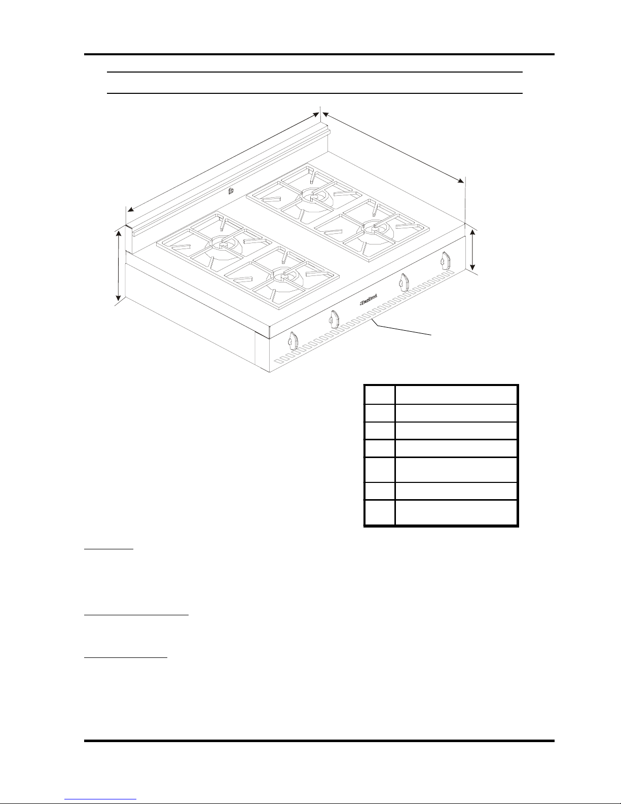
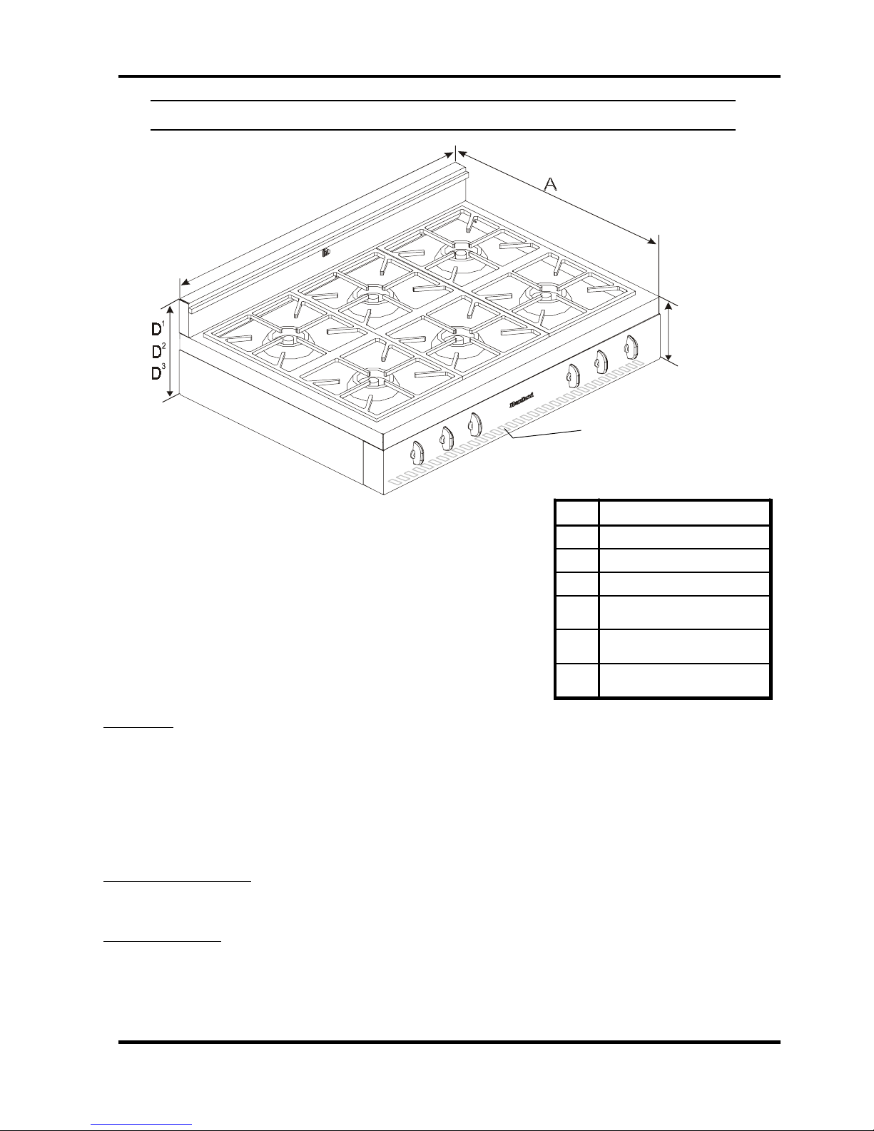
Installation Diagram- 30” Legacy Cooktop Model 3800
g
A
C
D
D
D
1
2
3
Figure 1
T able 1
B
Air intake slots on
underside of control panel
must not be obstructed or
covered.
Dim 30" Legacy Cooktop
A
B
C
1
D
2
D
3
D
26 5/8" (68cm)
8 1/4" (21cm)
29 3/4" (76 cm)
Standard profile: 14 1/4"(36 cm)
(as shown in dia
low profile: 10 1/8" (26 cm)
high back w/ shelf:
28 1/4" (72cm)
ram)
Clearances
• Minimum distance between the cooktop and a side wall above the cooktop surface is 6”
(see dim "J" in Table 2 on next page)
• Depth of cutout must not exceed 25”. (see dimension G) Air intake slots on underside of control panel
must not be obstructed or covered.
Electrical requirements:
• Electrical hookup must be done by a licenced electrician
• 120 Volts 60Hz .375 kW 3 prong plug 5 ft-(1.5 m) power cord included.
Gas Requirements:
• Gas hook-up must be done by a licensed gas fitter.
• Pressure requirements: Natural gas: 6” W.C. (min); LP gas: 11” W.C. (min)
• Connection: 1/2” NPT
• An accessible manual shut off valve must be installed at the appliance.
• Note: This unit contains a pre-set regulator
• Natural Gas/Propane Conversion kits are available - must be done by a licensed gas fitter
3
g
g
g
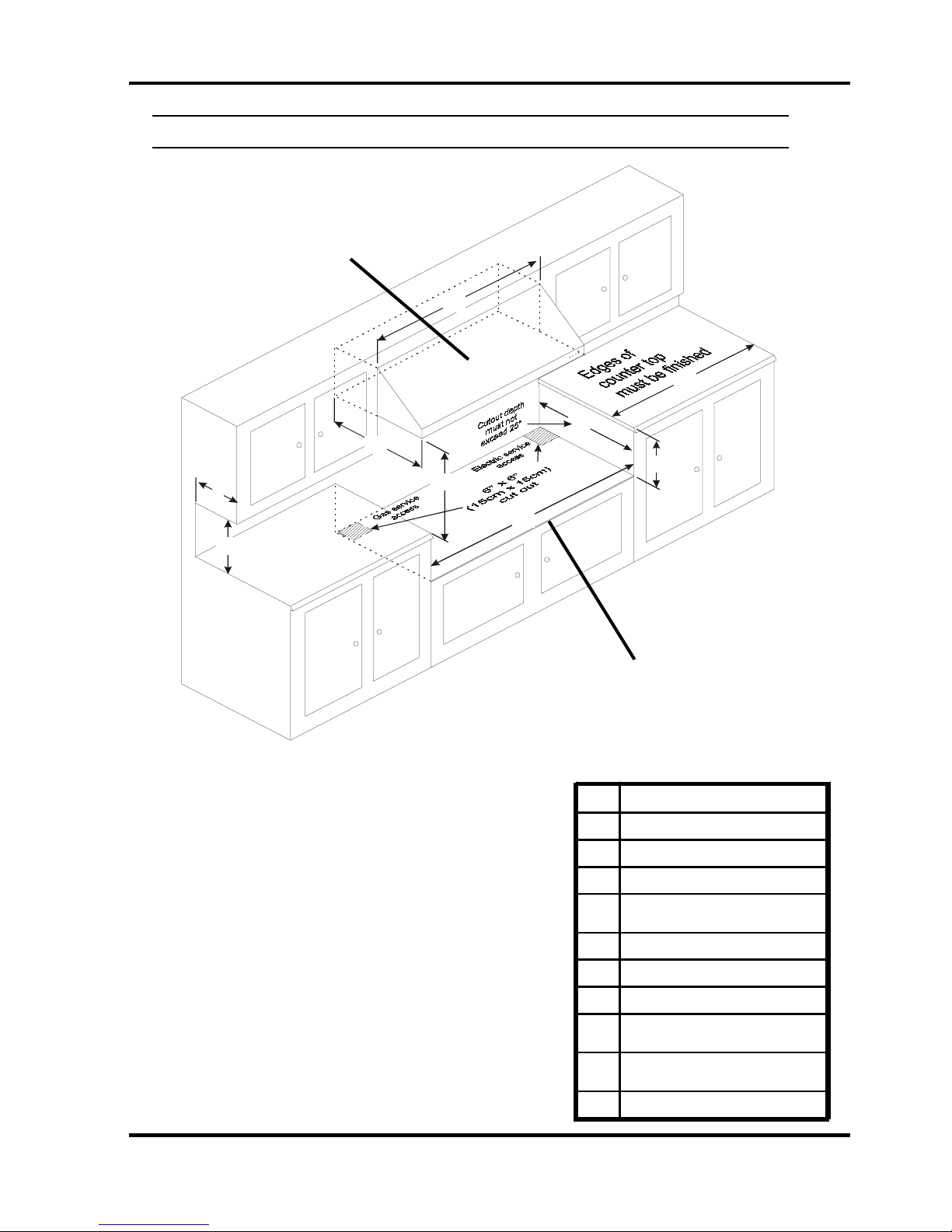
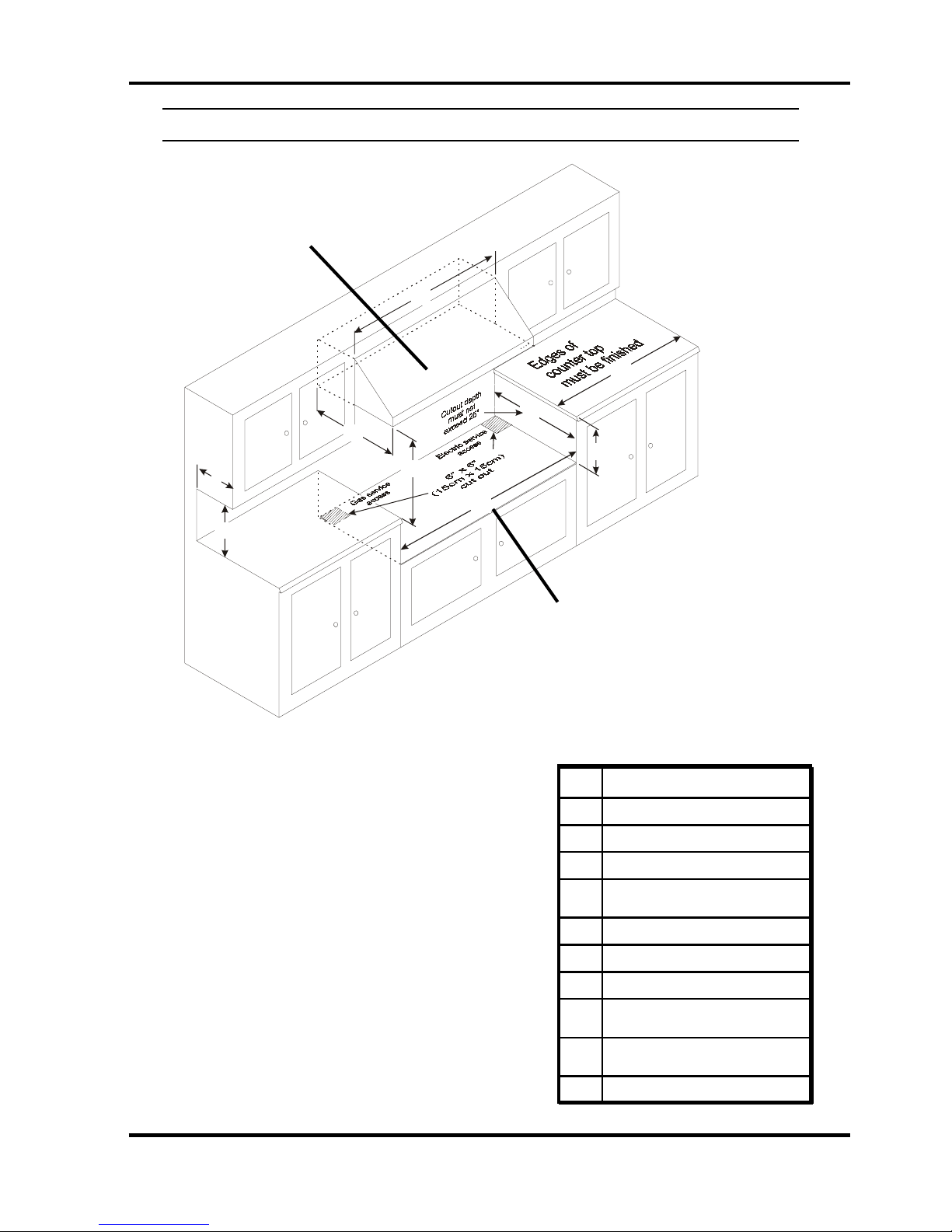
Clearance Diagram- 30” Legacy Cooktop Model 3800
An appropriate exhaust hood with a minimum of
450 CFM is required on all 30" Legacy cooktops
to ensure adequate and proper ventilation. For
superior ventilation we recommend using a 36”
hood, however a 30” hood is adequate.
L
G
M
1 2
K
O
NN
I
J
H
Figure 2
Note: If cooktop must stand beside a refrigerator, it is
important for proper air circulation that there be at least 5” (13
cm) of space between the two appliances.
T able 2
Note: Support deck must be able to
support a total weight of
4 burner model: 175 lbs
Dim 30" Legacy Cooktop
G
H
I
J
K
L
M
1
N
2
N
O
Maximum 2 5" (63cm)
Maximum 7 3/4" (21cm)
30" (77 cm)
Minimum 6 " (15cm)
left and ri
Specify Width of Hood
30" min to 36" max (76-92cm)
for standard and hi
30" min to 32 "max (76-82cm)
for low profile back
ht s ide
13"(33cm)
24" (61cm)
h back guar d
18" (45cm)
uard
4
Installation Diagram- 36” Legacy Cooktop Model 3820
C
Air intake slots on underside
of control panel must not be
obstructed or covered.
Dim 36" Legacy Cooktop
Figure 1
A
B
C
1
D
26 5/8" (68cm)
8 1/4" (21cm)
Standard profile: 14 1/4" (36cm)
(as shown in diagram)
B
36" (91cm)
low profile: 10 1/8" (26 cm)
2
D
high back w/ shelf:
28 1/4" (72cm)
T able 1
3
D
Clearances
• Minimum distance between the cooktop and a side wall above the cooktop surface is 6”
(see dim "J in Table 2 on next page)
• 0” Clearance to the back of the cooktop may be obtained when installing the appliance against a non-combustible
wall or with the installation of our Splashback Kit. Responsibility for ensuring that the rear wall is non-combustible
lies with the owner or end user. (check local building codes) - if wall behind cooktop is deemed combustible and
our splashback kit is not installed, then the minimum spacing from the back of stove to nearest combustible wall is 6”
• Depth of cutout must not exceed 25”. (see dimension G) Air intake slots on underside of control panel must not
be obstructed or covered.
Electrical requirements:
• Electrical hookup must be done by a licenced electrician
• 120 Volts 60Hz .375 kW 3 prong plug 5 ft-(1.5 m) power cord included.
Gas Requirements:
• Gas hook-up must be done by a licensed gas fitter.
• Pressure requirements: Natural gas: 6” W.C. (min); LP gas: 11” W.C. (min)
• Connection: 1/2” NPT
• An accessible manual shut off valve must be installed at the appliance.
• Note: This unit contains a pre-set regulator.
• Natural Gas/Propane Conversion kits are available - must be done by a licensed gas fitter
5
g
g
g
Clearance Diagram- 36” Legacy Cooktop Model 3820
An appropriate exhaust hood with a minimum of
900 CFM is required on all 36" Legacy cooktops
to ensure adequate and proper ventilation. For
superior ventilation we recommend using a 42”
hood, however a 36” hood is adequate.
L
J
G
M
1 2
K
NN
I
O
H
Figure 2
Note: If cooktop must stand beside a refrigerator, it is
important for proper air circulation that there be at least 5” (13
cm) of space between the two appliances.
Note: Support deck must be able to
support a total weight of
Grill model : 200 lbs
6 burner model: 220 lbs
Dim 36" Legacy Cooktop
G
H
I
J
K
L
M
30" min to 36" max (76-92cm)
1
N
for standard and hi
30" min to 32" max (76-82cm)
2
N
T able 2
O
Maximum 2 5" (63cm)
Maximum 7 3/4" (21cm)
36 1/4" (92cm)
Minimum 6" (15cm)
left and ri
Specify Width of Hood
for low profile back
ht si de
13"(33cm)
24" (61cm)
h back guar d
uard
18" (45cm)
6
g
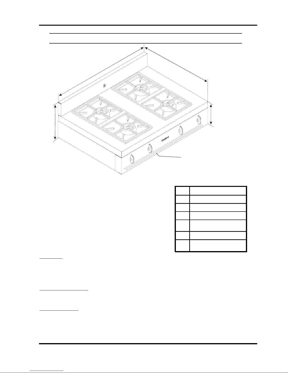
Installation Diagram- 30” Metro Cooktop Model 3805
A
C
1
D
2
D
3
D
Air intake slots on underside
of control panel must not be
obstructed or covered.
B
Figure 1
Dim 30" Metro Cooktop
A
B
C
1
D
2
D
3
D
T able 1
Clearances
• Minimum distance between the cooktop and a side wall above the cooktop surface is 6”
(see dim "J" in Table 2 on next page)
• Depth of cutout must not exceed 25”. (see dimension G) Air intake slots on underside of control panel must
not be obstructed or covered.
Electrical requirements:
• Electrical hookup must be done by a licenced electrician
• 120 Volts 60Hz .375 kW 3 prong plug 5 ft-(1.5 m) power cord included.
Gas Requirements:
• Gas hook-up must be done by a licensed gas fitter.
• Pressure requirements: Natural gas: 6” W.C. (min); LP gas: 11” W.C. (min)
• Connection: 1/2” NPT
• An accessible manual shut off valve must be installed at the appliance.
• Note: This unit contains a pre-set regulator.
• Natural Gas/Propane Conversion kits are available - must be done by a licensed gas fitter
26 5/8" (68cm)
8 1/4" (21cm)
29 3/4" (76 cm)
Standard profile:12 3/4"(32 cm)
(as shown in dia
low profile: 10 1/8" (26 cm)
high back w/ shelf:
28 1/4" (72cm)
ram)
7
 Loading...