

Page 1
OWNER’S MANUALOWNER’S MANUAL
OWNER’S MANUAL
OWNER’S MANUALOWNER’S MANUAL
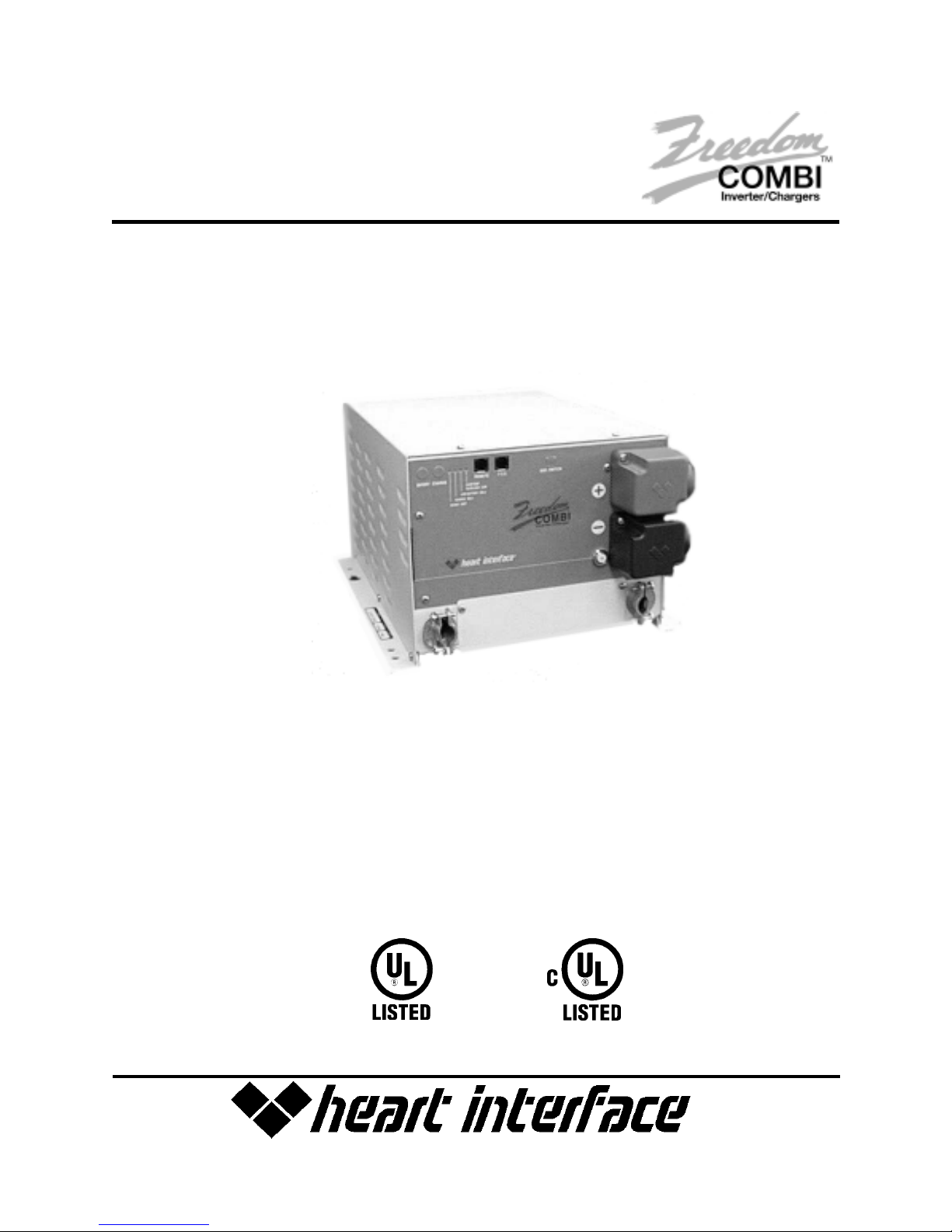
FREEDOM 458 Series COMBIFREEDOM 458 Series COMBI
FREEDOM 458 Series COMBI
FREEDOM 458 Series COMBIFREEDOM 458 Series COMBI
INVERTER/CHARGERINVERTER/CHARGER
INVERTER/CHARGER
INVERTER/CHARGERINVERTER/CHARGER
TMTM
TM
TMTM
INFORMA INFORMA
INFORMA
INFORMA INFORMA
*Manual includes all models of Freedom 458 Inverter/Charger
TION IN THIS MANUALTION IN THIS MANUAL
TION IN THIS MANUAL
TION IN THIS MANUALTION IN THIS MANUAL
Model 10
Model 15
Model 20
Model 25
Model 30
IS SUBJECT T IS SUBJECT T
IS SUBJECT T
IS SUBJECT T IS SUBJECT T
O CHANGE WITHOUT NOTICEO CHANGE WITHOUT NOTICE
O CHANGE WITHOUT NOTICE
O CHANGE WITHOUT NOTICEO CHANGE WITHOUT NOTICE
®
Part No. 90-0123-00
Libertycombi.p65 11/05/99
1
Page 2

Thank you for purchasing a Heart Interface Freedom 458 Series Combi
Inverter/
TM
Charger. Heart Interface takes pride in manufacturing quality products specifically
designed to meet your power requirements.
Freedom Combi Inverter/Chargers provide silent, efficient and reliable AC power for a
variety of applications. They feature “hands-free” operation, automatic 3-stage battery
charging and automatic AC transfer switching. For your convenience, service is available
world-wide by qualified service centers.
If you have any questions about your Freedom Combi, please contact Heart
Interface toll free:
(800) 446-6180(800) 446-6180
(800) 446-6180.
(800) 446-6180(800) 446-6180
For technical support and additional information about Heart Interface products, visit
wwwwww
our web site at
.heartinterface.com.heartinterface.com
www
.heartinterface.com or send us e-mail:
wwwwww
.heartinterface.com.heartinterface.com
SAFETYSAFETY
SAFETY
SAFETYSAFETY
Safety information for installation andSafety information for installation and
Safety information for installation and
Safety information for installation andSafety information for installation and
operation is contained throughout thisoperation is contained throughout this
operation is contained throughout this
operation is contained throughout thisoperation is contained throughout this
manual where it applies and is not includedmanual where it applies and is not included
manual where it applies and is not included
manual where it applies and is not includedmanual where it applies and is not included
in this summaryin this summary
in this summary
in this summaryin this summary
Definitions:Definitions:
Definitions:
Definitions:Definitions:
WW
arning statements arning statements
W
arning statements identify conditions or
WW
arning statements arning statements
practices which could result in personal injury,
loss of life, damage to equipment or other
property.
The statements, specifications and instructions in this publication are believed to be correct. No warranty is made,The statements, specifications and instructions in this publication are believed to be correct. No warranty is made,
The statements, specifications and instructions in this publication are believed to be correct. No warranty is made,
The statements, specifications and instructions in this publication are believed to be correct. No warranty is made,The statements, specifications and instructions in this publication are believed to be correct. No warranty is made,
expressed or implied by the seller or manufacturer with respect to any results or lack thereof from the use ofexpressed or implied by the seller or manufacturer with respect to any results or lack thereof from the use of
expressed or implied by the seller or manufacturer with respect to any results or lack thereof from the use of
expressed or implied by the seller or manufacturer with respect to any results or lack thereof from the use ofexpressed or implied by the seller or manufacturer with respect to any results or lack thereof from the use of
information in this publication and no liability is assumed for any direct or consequential damages, personal loss orinformation in this publication and no liability is assumed for any direct or consequential damages, personal loss or
information in this publication and no liability is assumed for any direct or consequential damages, personal loss or
information in this publication and no liability is assumed for any direct or consequential damages, personal loss orinformation in this publication and no liability is assumed for any direct or consequential damages, personal loss or
injurinjur
yy
. .
All statements made herAll statements made her
injur
y
.
All statements made her
injurinjur
yy
. .
All statements made herAll statements made her
Corporation. All rights reserved.Corporation. All rights reserved.
Corporation. All rights reserved.
Corporation. All rights reserved.Corporation. All rights reserved.
SUMMAR SUMMAR
SUMMAR
SUMMAR SUMMAR
..
.
..
ein arein ar
e strictly to be used ore strictly to be used or
ein ar
e strictly to be used or
ein arein ar
e strictly to be used ore strictly to be used or
YY
Y
YY
Fuse Replacement Fuse Replacement
Fuse Replacement For continued protection
Fuse Replacement Fuse Replacement
against the possibility of fire, replace the fuse
only with a fuse of the specified voltage,
current and type ratings.
Power Source Power Source
Power Source T o avoid damage, operate the
Power Source Power Source
equipment only within the specified AC (line)
and DC (battery) voltages.
Servicing Servicing
Servicing To reduce the risk of electric shock
Servicing Servicing
do not open this unit. There are no user
serviceable parts inside. Refer all service to
qualified personnel.
r r
elied on at the userelied on at the user
r
elied on at the user
r r
elied on at the userelied on at the user
’’
s risk. © 1998 Hears risk. © 1998 Hear
’
s risk. © 1998 Hear
’’
s risk. © 1998 Hears risk. © 1998 Hear
t Interfacet Interface
t Interface
t Interfacet Interface
2
Part No. 90-0123-00
Libertycombi.p65 11/05/99
Page 3

TT
ABLE OF CONTENTSABLE OF CONTENTS
T
ABLE OF CONTENTS
TT
ABLE OF CONTENTSABLE OF CONTENTS
IntroductionIntroduction
Introduction. . . . . . . . . . . . . . . . . . . . . . . . .
IntroductionIntroduction
Things Things
Things
Things Things
OperationOperation
Operation . . . . . . . . . . . . . . . . . . . . . . . . . .
OperationOperation
Optional Remote Control Panels . . . . . . . . .10Optional Remote Control Panels . . . . . . . . .10
Optional Remote Control Panels . . . . . . . . .10
Optional Remote Control Panels . . . . . . . . .10Optional Remote Control Panels . . . . . . . . .10
BatteriesBatteries
Batteries . . . . . . . . . . . . . . . . . . . . . . . . . .
BatteriesBatteries
Battery ChargingBattery Charging
Battery Charging. . . . . . . . . . . . . . . . . . . .
Battery ChargingBattery Charging
Battery Charger VBattery Charger V
Battery Charger V
Battery Charger VBattery Charger V
Installation Precautions Installation Precautions
Installation Precautions . . . . . . . . . . . . . .
Installation Precautions Installation Precautions
InstallationInstallation
Installation . . . . . . . . . . . . . . . . . . . . . . . . .
InstallationInstallation
YY
ou Should Knowou Should Know
Y
ou Should Know . . . . . . . . . . . . .
YY
ou Should Knowou Should Know
Circuit Breaker Protection
Thermostat Controlled Cooling
Inverter Idle Circuit
Low and High Battery Shutdown
Power Sharing
Temperature Sensitive Charging
Battery Types
Battery Interconnection
Battery Bank Ratings and Sizing
Freedom Battery Chargers
oltage Toltage T
oltage T
oltage Toltage T
Key Installation Points
Grounding
Neutral Bonding
AC Wiring
AC Input
AC Output
Ground Fault Circuit Interrupters
Remote Control Wiring
TSC T emperature Senstive Charging
DC Wiring
Battery Cable Fusing
Power ON Checks
able able
able . . . . . . . . .
able able
1515
15
1515
2020
20
2020
2121
21
2121
2222
22
2222
11
1
11
44
TT
roubleshooting roubleshooting
4
T
roubleshooting . . . . . . . . . . . . . . . . . . . . .
44
TT
roubleshooting roubleshooting
LED Fault Status
55
5
55
Things to Check
Glossary Glossary
Glossary . . . . . . . . . . . . . . . . . . . . . . . . . . . .
Glossary Glossary
Specifications Specifications
Specifications . . . . . . . . . . . . . . . . . . . . . . . . .
Specifications Specifications
Installation Diagrams Installation Diagrams
Installation Diagrams . . . . . . . . . . . . . . . . . . .
Installation Diagrams Installation Diagrams
WW
arranty arranty
W
arranty . . . . . . . . . . . . . . . . . . .
WW
arranty arranty
77
7
77
11
1
11
3131
31
3131
3333
33
3333
3535
35
3535
3636
36
3636
4848
48
4848
Not recommended for use in marine environmentNot recommended for use in marine environment
Not recommended for use in marine environment
Not recommended for use in marine environmentNot recommended for use in marine environment
Part No. 90-0123-00
Libertycombi.p65 11/05/99
3
Page 4

INTRODUCTIONINTRODUCTION
INTRODUCTION
INTRODUCTIONINTRODUCTION
This owner’s manual describes the
Freedom 458 Series Combi
Chargers from Heart Interface. These units
perform three distinct functions:
1. DC to AC power inverting.1. DC to AC power inverting.
1. DC to AC power inverting.
1. DC to AC power inverting.1. DC to AC power inverting.
2. Automatic transfer switching between2. Automatic transfer switching between
2. Automatic transfer switching between
2. Automatic transfer switching between2. Automatic transfer switching between
inverter power and incoming inverter power and incoming
inverter power and incoming
inverter power and incoming inverter power and incoming
3. Automatic 3-Stage Battery charging plus3. Automatic 3-Stage Battery charging plus
3. Automatic 3-Stage Battery charging plus
3. Automatic 3-Stage Battery charging plus3. Automatic 3-Stage Battery charging plus
manual battery equalizing.manual battery equalizing.
manual battery equalizing.
manual battery equalizing.manual battery equalizing.
• The inverter provides regulated 120 volt AC
power at a crystal controlled frequency from a
deep cycle battery bank and is rated at:
Freedom 10Freedom 10
Freedom 10
Freedom 10Freedom 10
Freedom 15 & 15D Freedom 15 & 15D
Freedom 15 & 15D
Freedom 15 & 15D Freedom 15 & 15D
Freedom 20 & 20D Freedom 20 & 20D
Freedom 20 & 20D
Freedom 20 & 20D Freedom 20 & 20D
Freedom 25 Freedom 25
Freedom 25
Freedom 25 Freedom 25
Freedom 30 Freedom 30
Freedom 30
Freedom 30 Freedom 30
The output is a modified sine wave and is
compatible with most appliances, tools and
other 120 VAC equipment. (Note: Certain laser
printers, breadmakers, digital clocks and
small battery chargers may not operate on
modfied sinewave.) An idle mode reduces battery power consumption when loads are removed from the inverter. There is a low battery
cutout protection circuit and
momentary surge power of more than twice
the inverter rating for starting electric motors.
High efficiency insures the longest possible
battery life between charges.
• The internal transfer switch allows the
Freedom Inverter/Charger to be connected to
an external AC source and transfer the source
2500 watts 2500 watts
2500 watts
2500 watts 2500 watts
Inverter/
TM
AC powerAC power
AC power
AC powerAC power
1000 watts1000 watts
1000 watts
1000 watts1000 watts
1500 watts1500 watts
1500 watts
1500 watts1500 watts
2000 watts2000 watts
2000 watts
2000 watts2000 watts
3000 watts3000 watts
3000 watts
3000 watts3000 watts
..
.
..
power through directly to the loads. When the
external AC power source is disconnected, the
transfer switch allows automatic switching
back to the inverter.
The Freedom Inverter/Charger operates
as a self-contained backup power system, just
add batteries.
• Freedom battery chargers are electronically
controlled and rated at a maximum output
current:
Freedom 10Freedom 10
Freedom 10
Freedom 10Freedom 10
Freedom 15 & 15D Freedom 15 & 15D
Freedom 15 & 15D
Freedom 15 & 15D Freedom 15 & 15D
Freedom 20 & 20D Freedom 20 & 20D
Freedom 20 & 20D
Freedom 20 & 20D Freedom 20 & 20D
Freedom 25 Freedom 25
Freedom 25
Freedom 25 Freedom 25
Freedom 30 140 Amps DC Freedom 30 140 Amps DC
Freedom 30 140 Amps DC
Freedom 30 140 Amps DC Freedom 30 140 Amps DC
They are designed to rapidly and optimally
charge wet, gel, or Absorbed Glass Mat
(AGM)** cell deep-cycle batteries. Battery
charging is automatically accomplished in 3
stages: Bulk Charge, Acceptance Charge and
Float Charge.
Using a Remote Control Panel or Link
Instrumentation, a manually engaged
Equalizing Charge cycle is possible. Simple,
automatic operation is made possible by the
microprocessor in the Freedom Inverter/
Charger. I n most cases, no attention or
maintenance is required.
Electronic ProtectionElectronic Protection
Electronic Protection
Electronic ProtectionElectronic Protection
Fast-acting electronic circuits protect
the inverter from overloads and short circuits.
Other protection includes a low and high
battery voltage cutoff and automatic shutdown
if an over temperature condition occurs. When
the fault condition is corrected, the unit will
automatically reset. Example: remove
overload, charge batteries or allow to cool.
50 Amps DC50 Amps DC
50 Amps DC
50 Amps DC50 Amps DC
75 Amps DC75 Amps DC
75 Amps DC
75 Amps DC75 Amps DC
100 Amps DC100 Amps DC
100 Amps DC
100 Amps DC100 Amps DC
130 Amps DC130 Amps DC
130 Amps DC
130 Amps DC130 Amps DC
4
**Battery type selection is set on the front of the unit
or with an optional remote
Link Instrument).
(Remote Control Panel or
Part No. 90-0123-00
Libertycombi.p65 11/05/99
Page 5

THINGS YOU SHOULD KNOWTHINGS YOU SHOULD KNOW
THINGS YOU SHOULD KNOW
THINGS YOU SHOULD KNOWTHINGS YOU SHOULD KNOW
Circuit Breaker ProtectionCircuit Breaker Protection
Circuit Breaker Protection
Circuit Breaker ProtectionCircuit Breaker Protection
The Freedom Inverter/Charger is
supplemental breaker protected.
The INVERT/CHARGE breaker on the front
of the unit protects against sustained inverter/
charger over current conditions.
These breakers are reset by pushing the
button back in.
The output circuit breakers protect the output
AC circuits. Models are available with one or
two outputs.
Thermostat Controlled CoolingThermostat Controlled Cooling
Thermostat Controlled Cooling
Thermostat Controlled CoolingThermostat Controlled Cooling
Freedom Inverter/Chargers are equipped
with a thermostatically-controlled fan that cools
the unit so it can operate continually at its rated
Circuit Breaker ProtectionCircuit Breaker Protection
Circuit Breaker Protection
Circuit Breaker ProtectionCircuit Breaker Protection
INV/CHG
1010
10
1010
1515
15
1515
15D15D
15D
15D15D
2020
20
2020
20D20D
20D
20D20D
25 25
25
25 25
2525
25
2525
3030
30
3030
*Circuit breaker configurations include 15/15,
*Note: Supplemental circuit breakers are
reset by pushing the button back in. The
fault must be removed before resetting
the circuit breaker. Integral branch circuit
rated breakers are reset by setting the
appropriate breaker switch to the “on” position. The fault must be removed before
resetting the circuit breaker
If a 30-Ampere service supplies the input to the unit, a model with integral
branch circuit rated breakers allows direct wiring from the unit to the load.
15
20
20
25
25
30
30
15/20, and 20/20
OUT 1
N/A
N/A
15/20*
N/A
15/20*
N/A
N/A
OUT 2
N/A
N/A
15/20*
N/A
15/20*
N/A
N/A
Units with only supplemental circuit breakers
between the unit and the load. Appropriate
wire gauges must be used throughtout the installation. Refer to NEC specifications.
Inverter Idle CircuitInverter Idle Circuit
Inverter Idle Circuit
Inverter Idle CircuitInverter Idle Circuit
This automatic energy saving feature
reduces battery power consumption when no
AC load is present. Response from idle is
instantaneous. In most cases, the operation of
the idle circuit is not noticeable. Use of the
Remote Control Panel or Link Instrumentation
allows the idle threshold to be adjusted. The
unit does not put out 120 volts when in idle. To
bring the unit out of the idle condition, apply a
load.
Low and High Battery ShutdownLow and High Battery Shutdown
Low and High Battery Shutdown
Low and High Battery ShutdownLow and High Battery Shutdown
When in inverter mode, if the battery
voltage drops to 10.0 volts, the inverter will
automatically shut off. Charge the batteries to
13.5 volts to automatically resume operation.
Voltage shut down also occurs for a high
battery condition at 15.5 volts. Operation will
resume automatically when the battery voltage
drops below 15.5 volts. Check all DC sources
on the system for the reason for the excessive
voltage.
Power SharingPower Sharing
Power Sharing
Power SharingPower Sharing
When connected to an external AC
source the battery charger and transfer
functions are engaged. A unique Power
Sharing feature automatically reduces the AC
power consumption of the battery charger
allowing necessary AC power to go to the load.
This prevents the source AC INPUT circuit
breaker from tripping within the specified rating
of the AC circuit breaker.
The Power Sharing set point of each unit
has a factory default setting of 30 Amps. This
can be changed using the Remote Control
Panel or Link Instrumentation.
Part No. 90-0123-00
Libertycombi.p65 11/05/99
5
Page 6
THINGS YOU SHOULD KNOWTHINGS YOU SHOULD KNOW
THINGS YOU SHOULD KNOW
THINGS YOU SHOULD KNOWTHINGS YOU SHOULD KNOW
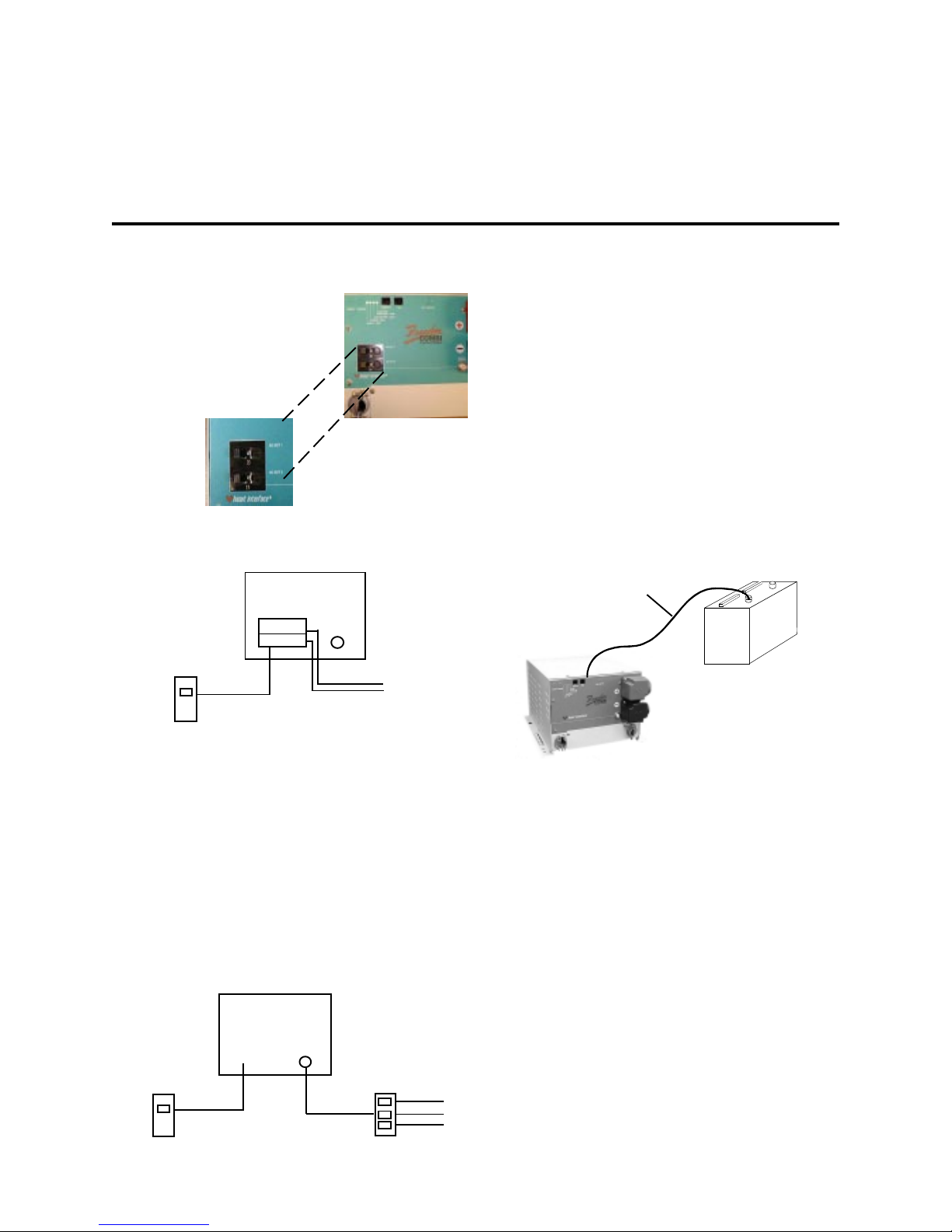
Freedom 458 Series Combi
with Branch Circuit Rated Breakers
Branch Circuit Breakers
20 Amp
15 Amp
IntegralIntegral
Integral
IntegralIntegral
Branch Circuit Rated BreakersBranch Circuit Rated Breakers
Branch Circuit Rated Breakers
Branch Circuit Rated BreakersBranch Circuit Rated Breakers
Models 15D&20DModels 15D&20D
Models 15D&20D
Models 15D&20DModels 15D&20D
Inverter/Charger
Branch Circuit
Rated Breaker
INPUT
Shown:
Freedom 20D
81-2022-12
To LOADS
TT
emperature Sensitive Chargingemperature Sensitive Charging
T
emperature Sensitive Charging
TT
emperature Sensitive Chargingemperature Sensitive Charging
When the supplied battery temperature
sensor is connected to the unit and the
batteries, the charge voltage is controlled
based on battery temperature. The charger
adjusts the charge voltage to the best level,
minimizing water loss in wet cell batteries.
Charge voltage regulation optimizes the battery
life cycle.
TSC SensorTSC Sensor
TSC Sensor
TSC SensorTSC Sensor
BatteryBattery
Battery
BatteryBattery
Units with integral branch circuit rated
breaker protection require a branch circuit
rated breaker at the input only. The output to
two branch loads may be connected directly
at the unit output.
NOTE: The INPUT branch rated circuit
breaker may be at the source of AC power
(i.e. shore power or generator or from a
main AC distribution panel located before
the input of the unit).
SupplementalSupplemental
Supplemental
SupplementalSupplemental
Branch Circuit Rated BreakersBranch Circuit Rated Breakers
Branch Circuit Rated Breakers
Branch Circuit Rated BreakersBranch Circuit Rated Breakers
Branch Circuit
Rated Breaker
6
Inverter/Charger
INPUT
*Models 25&30 include
second input&output
ModelsModels
Models
ModelsModels
10,15,20,25,3010,15,20,25,30
10,15,20,25,30
10,15,20,25,3010,15,20,25,30
Branch Circuit
Rated Breaker
Part No. 90-0123-00
Libertycombi.p65 11/05/99
Page 7

OPERAOPERA
OPERA
OPERAOPERA
TIONTION
TION
TIONTION
The Freedom Inverter/Charger provides
120 volt AC power from auxiliary DC batteries,
automatic battery charging and automatic AC
transfer switching between an external AC
source and inverter mode.
External AC PowerExternal AC Power
External AC Power
External AC PowerExternal AC Power
When external AC power is available, the
3-stage battery charger, transfer switching,
and Power Sharing automatically function.
When external AC power is not available
and the INVERT switch is ON (either through
the auxiliary switch or the INVERT button on
the remote), the inverter will automatically turn
ON. If the INVERT switch is OFF (the INVERT
LED will not be illuminated), the inverter will be
OFF.
If installed with the Remote Control Panel
or Link Instrumentation, the unit will be set up
and controlled from the remote. Refer to the
remote manual for more information.
Front Panel Controls and IndicatorsFront Panel Controls and Indicators
Front Panel Controls and Indicators
Front Panel Controls and IndicatorsFront Panel Controls and Indicators
INVERT MODEINVERT MODE
INVERT MODE
INVERT MODEINVERT MODE
The INVERT push-button switch is
located on the front of the unit and has two
functions:
• Turn the inverter ON/OFF and reset after
a fault condition. Pressing the INVERT switch
turns the inverter ON. The green INVERT LED
will be ON when the inverter is inverting.
When the inverter is ON, pressing the INVERT
switch turns the inverter OFF.
INVERTINVERT
INVERT
INVERTINVERT
CHARGECHARGE
CHARGE
CHARGECHARGE
• Battery type setup. To enter the battery
type select mode, press and hold the INVERT
switch for five seconds. The status LEDs will
change from indicating status information to
indicating battery type. The selection of the
battery type is made with the Charge switch.
Turning the INVERT OFF will reduce
battery power consumption to a very low level.
This is recommended if the unit will not be
used for an extended period of time.
CHARGE MODECHARGE MODE
CHARGE MODE
CHARGE MODECHARGE MODE
The CHARGE push-button switch has
two functions:
T T
urn the charger ON and OFFurn the charger ON and OFF
•
T
urn the charger ON and OFF
T T
urn the charger ON and OFFurn the charger ON and OFF
If external AC is present, pressing the
CHARGE switch will turn the charger ON.
The green CHARGE LED will be ON when the
charger is charging. When the charger is ON,
pressing this switch will turn the charger OFF.
Select the battery type Select the battery type
•
Select the battery type After holding
Select the battery type Select the battery type
the INVERT switch for 5 seconds, press the
CHARGE switch to select the battery type.
One of the four LEDs will rapidly blink
indicating the present battery type setting.
Press the CHARGE switch again to change
the battery type. Continue to press until the
desired battery type is selected. If the
CHARGE switch is not pressed for 5 seconds,
the unit will return to normal operation and the
battery type selection will have been made.
When the 12 volt input to the unit is
disconnected, the battery type setting is stored
in non-volatile memory. When the unit is
reconnected, the battery type selection
conveniently returns to the setting.
Freedom 20Freedom 20
Freedom 20
Freedom 20Freedom 20
Part No. 90-0123-00
Libertycombi.p65 11/05/99
7
Page 8
OPERAOPERA
OPERA
OPERAOPERA
STST
AA
TUS LEDsTUS LEDs
ST
A
TUS LEDs
STST
AA
TUS LEDsTUS LEDs
TIONTION
TION
TIONTION
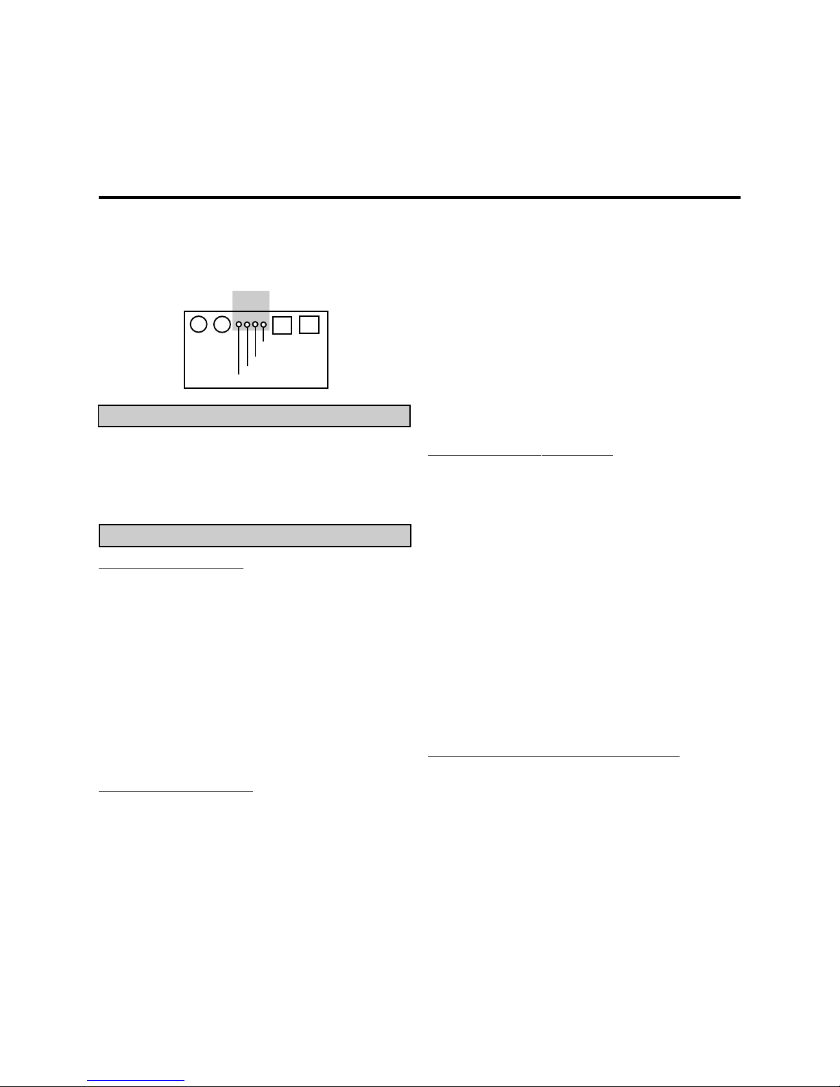
Each Status LED performs two functions,
providing battery type selection and operation
status.
Status LEDsStatus LEDs
Status LEDs
Status LEDsStatus LEDs
CHARGECHARGE
CHARGE
CHARGECHARGE
INVERTINVERT
INVERT
INVERTINVERT
Battery TBattery T
Battery T
Battery TBattery T
OVERTEMPOVERTEMP
OVERTEMP
OVERTEMPOVERTEMP
OVERLOAD / AGMOVERLOAD / AGM
OVERLOAD / AGM
OVERLOAD / AGMOVERLOAD / AGM
LOW BATTERY / GEL 2LOW BATTERY / GEL 2
LOW BATTERY / GEL 2
LOW BATTERY / GEL 2LOW BATTERY / GEL 2
CHARGE / GEL1CHARGE / GEL1
CHARGE / GEL1
CHARGE / GEL1CHARGE / GEL1
INVERT / WETINVERT / WET
INVERT / WET
INVERT / WETINVERT / WET
ype Selectionype Selection
ype Selection
ype Selectionype Selection
REMOTEREMOTE
REMOTE
REMOTEREMOTE
TSCTSC
TSC
TSCTSC
After holding the INVERT button down for
5 seconds, use the CHARGE button to select
battery type :
WET GEL 1 GEL 2 AGM
Operation StatusOperation Status
Operation Status
Operation StatusOperation Status
INVERT INVERT
INVERT - Green LED
INVERT INVERT
The INVERT push-button switch is located on
the front of the unit.
• When the LED is solid green, the unit is
in invert mode. This occurs by pressing the
INVERT switch for (3-5 seconds).
• When the LED is blinking slowly (1 time
per second), the inverter is in standby with AC
power applied and the transfer switch engaged
• Press the INVERT switch again to turn
the inverter OFF.
CHARGE CHARGE
CHARGE - Green LED
CHARGE CHARGE
• The CHARGE push-button switch is located on the fornt of the unit.
When external AC is applied to the AC input of the unit, the charger automatically turns
ON. The CHARGE LED will be solid green.
• When the LED is blinking slowly, (1 time
per second) the charger is ready, but external
AC power is not available.
• Press the CHARGE switch again to turn
the charger OFF. The charger defaults to ON
when operation without a remote or with the
Freedom Remote Control Panel.
• When the LED is OFF, the charger has
been manually turned OFF. This can only be
accomplished while AC power is being
supplied.
NOTE: When AC power is available, the
default setting for the charger is ON. If the unit
was manually turned OFF and AC power is interrupted and becomes available again, the
charger will return to ON.
LOW BALOW BA
LOW BA
LOW BALOW BA
TTERTTER
YY
TTER
TTERTTER
••
• When the LED is OFF the battery
••
Y
- Red LED
YY
voltage is normal, between 10.5 and 15.0
volts DC.
• When the LED is solid red, it indicates a
battery warning condition, the battery voltage is
below 10.5 volts DC or above 15.0 volts DC.
• When the LED is blinking slowly, (1 time
per second), a battery shutdown has occurred.
The voltage is either below 10.0 volts DC or
above 15.5 volts DC.
• When the LED is blinking rapidly (5
times per second), a potential problem in the
DC system has been detected. Check your
batteries, battery cables and DC loads.
OVERTEMP/OVERLOAD OVERTEMP/OVERLOAD
OVERTEMP/OVERLOAD - Red LED
OVERTEMP/OVERLOAD OVERTEMP/OVERLOAD
••
• When the LED is Off operation is
••
normal.
• When the LED is red, there is an over
temp or overload condition. Check for
excessive loads or short circuit on the output
of the inverter. Correct the condition and restart
by pushing the INVERT switch.
8
Part No. 90-0123-00
Libertycombi.p65 11/05/99
Page 9
• When the LED is blinking slowly (1 time
per second), an over current condition or a
short circuit has occured. The system has
shut OFF and will not automatically restart.
Correct the fault condition and manually restart
the system.
LowLow
Low
LowLow
BatteryBattery
Battery
BatteryBattery
OvertempOvertemp
Overtemp
OvertempOvertemp
OPERAOPERA
OPERA
OPERAOPERA
TSCTSC
TSC
RemoteRemote
Remote
RemoteRemote
TSCTSC
TIONTION
TION
TIONTION
Auxiliary PortAuxiliary Port
Auxiliary Port
Auxiliary PortAuxiliary Port
LOW BALOW BA
LOW BA
LOW BALOW BA
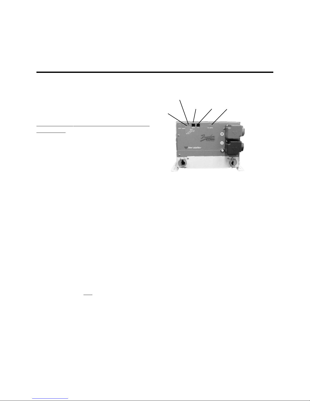
- Red LEDs
backfeed has been detected. A backfeed
occurs when AC power from an external
source is connected to the output of the
inverter. Inspect wiring for possible input/output
wiring error. This condition will damage the unit
and must be corrected before further
operation.
TSC (TTSC (T
TSC (T
TSC (TTSC (T
sensor to measure battery temperature for
compensated charging. If no sensor is
connected the charge voltage levels are set to
defaults based on battery type.
OPTIONAL REMOTESOPTIONAL REMOTES
OPTIONAL REMOTES
OPTIONAL REMOTESOPTIONAL REMOTES
installation instructions included with the
remote.
TTERTTER
YY
TTER
TTERTTER
• When both LEDs are blinking, an AC
emperature Sensitive Charging)emperature Sensitive Charging)
emperature Sensitive Charging)
emperature Sensitive Charging)emperature Sensitive Charging)
This provides for the connection of a
If using one of the remotes, refer to the
& OVERTEMP/OVERLOAD & OVERTEMP/OVERLOAD
Y
& OVERTEMP/OVERLOAD
YY
& OVERTEMP/OVERLOAD & OVERTEMP/OVERLOAD
Note: When a Remote Control Panel or
Link is installed, the jumper included in the
parts plastic bag is
Switch Port (AUX SWITCH) on the front panel
of the inverter/charger. See page 23 for more
details.
Part No. 90-0123-00
Libertycombi.p65 11/05/99
notnot
not used in the Auxiliary
notnot
9
Page 10
OPTIONALOPTIONAL
OPTIONAL
OPTIONALOPTIONAL
Remote Control PanelRemote Control Panel
Remote Control Panel
Remote Control PanelRemote Control Panel
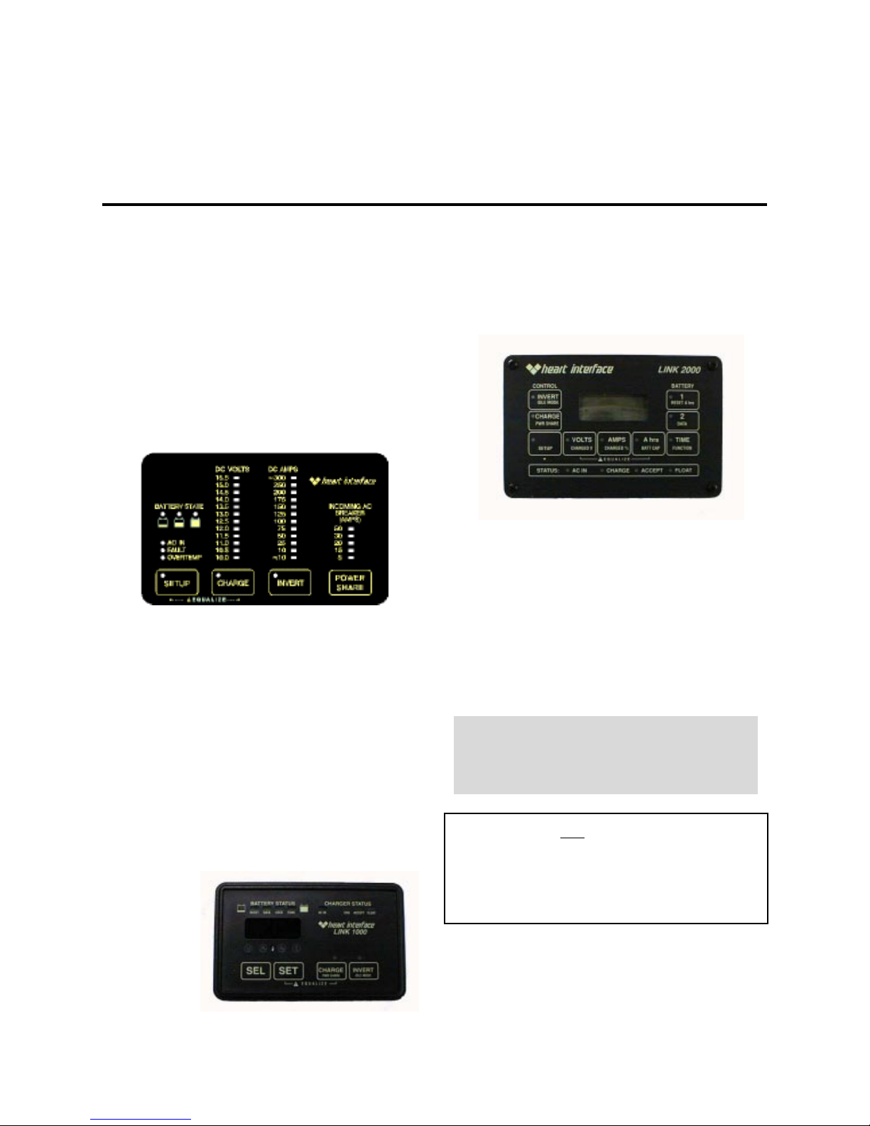
An optional remote control panel is
available. The LED bargraphs on the remote
control panel shows battery voltage and DC
current in both inverter and charger modes.
Easy to see red, yellow and green LEDs
show the battery state-of-charge. Power
Sharing, charger ON/OFF, inverter ON/OFF
controls are provided. Set up features include
selection of Idle Threshold, Battery Type and
Battery Capacity.
Remote Control PanelRemote Control Panel
Remote Control Panel
Remote Control PanelRemote Control Panel
REMOTE CONTROL REMOTE CONTROL
REMOTE CONTROL
REMOTE CONTROL REMOTE CONTROL
P P
ANELSANELS
P
ANELS
P P
ANELSANELS
LINK 2000LINK 2000
LINK 2000
LINK 2000LINK 2000
The Link 2000 has the same features as
the Link 1000, providing inverter/charger
control and complete battery state-of-charge
information. It monitors two battery banks.
LINK 2000LINK 2000
LINK 2000
LINK 2000LINK 2000
LINK 2000RLINK 2000R
LINK 2000R
LINK 2000RLINK 2000R
The Link 2000R adds the ability to
regulate an engine-driven alternator. The
precision regulator in the LINK 2000R allows
the alternator to be controlled as a 3-stage
battery charging system.
Advanced Remote Control PanelsAdvanced Remote Control Panels
Advanced Remote Control Panels
Advanced Remote Control PanelsAdvanced Remote Control Panels
Link InstrumentLink Instrument
Link Instrument
Link InstrumentLink Instrument
Advanced remote control panels are also
available: the Link 1000, 2000 and 2000R.
LINK 1000LINK 1000
LINK 1000
LINK 1000LINK 1000
Link 1000 controls the Freedom Inverter/
Charger and provides complete battery
state-of-charge information including DC
voltage, current, Amp-hours consumed, Time
Remaining and historical data for a single
battery bank.
LINK 1000LINK 1000
LINK 1000
LINK 1000LINK 1000
10
If Link Instrument is used to control the
inverter/charger, refer to the Link Owner ’ s
Manual for setup and control information.
Refer to the Remote Control PanelRefer to the Remote Control Panel
Refer to the Remote Control Panel
Refer to the Remote Control PanelRefer to the Remote Control Panel
or LINK Owneror LINK Owner
or LINK Owner
or LINK Owneror LINK Owner
installation and operation instructionsinstallation and operation instructions
installation and operation instructions
installation and operation instructionsinstallation and operation instructions
The jumper is The jumper is
The jumper is
The jumper is The jumper is
Switch Port on the front panel of theSwitch Port on the front panel of the
Switch Port on the front panel of the
Switch Port on the front panel of theSwitch Port on the front panel of the
inverter when the Remote Control Panelinverter when the Remote Control Panel
inverter when the Remote Control Panel
inverter when the Remote Control Panelinverter when the Remote Control Panel
or Link Instrument is used. See page 23or Link Instrument is used. See page 23
or Link Instrument is used. See page 23
or Link Instrument is used. See page 23or Link Instrument is used. See page 23
for more details.for more details.
for more details.
for more details.for more details.
notnot
not
notnot
’’
s Manual fors Manual for
’
s Manual for
’’
s Manual fors Manual for
installed in the AUX installed in the AUX
installed in the AUX
installed in the AUX installed in the AUX
Part No. 90-0123-00
Libertycombi.p65 11/05/99
Page 11
BABA
BA
BABA
Wet cell batteries will give off gas as a
natural result of charging and will experience
some water loss. It is
electrolyte level be checked frequentlyelectrolyte level be checked frequently
electrolyte level be checked frequently and
electrolyte level be checked frequentlyelectrolyte level be checked frequently
topped off with distilled water when necessary.
Follow the battery manufacturer ’s
recommendations for maintenance.
Never allow the top of the battery plates to
be exposed to air, as contamination of the cell
will result. Keep the top of batteries clean.
Always provide adequate ventilation for the
battery storage compartment.
TTERIESTTERIES
TTERIES
TTERIESTTERIES
very important that thevery important that the
very important that the
very important that thevery important that the
BABA
TTERTTER
YY
BA
TTER
BABA
TTERTTER
Freedom Inverter/Charger. These fall into three
broad categories: wet cell, gel cell and
Advanced AGM (Absorbed Glass Mat)
batteries.
Wet Cell BatteriesWet Cell Batteries
Wet Cell Batteries
Wet Cell BatteriesWet Cell Batteries
characterized by relatively thick internal plates
that are alloyed with antimony.
batteries are acceptable. Golf cartbatteries are acceptable. Golf cart
batteries are acceptable. Golf cart
batteries are acceptable. Golf cartbatteries are acceptable. Golf cart
batteries perform well and may have abatteries perform well and may have a
batteries perform well and may have a
batteries perform well and may have abatteries perform well and may have a
longer life.longer life.
longer life. These 6 volt batteries must be
longer life.longer life.
used in series connected in pairs.
quality deep-cycle batteries offer goodquality deep-cycle batteries offer good
quality deep-cycle batteries offer good
quality deep-cycle batteries offer goodquality deep-cycle batteries offer good
performance performance
performance and are available in a wide
performance performance
variety of sizes.
TYPES TYPES
Y
TYPES
YY
TYPES TYPES
Use only deep-cycle batteries with your
True deep-cycle wet cell batteries are
Common 12 volt marine/RV deep-cycleCommon 12 volt marine/RV deep-cycle
Common 12 volt marine/RV deep-cycle
Common 12 volt marine/RV deep-cycleCommon 12 volt marine/RV deep-cycle
HighHigh
High
HighHigh
Do not use ordinary car batteries or
engine starting batteries with your inverter/
charger. Beware of any battery that is rated in
Cold Cranking Amps (CCA). This is a rating
which applies only to engine starting batteries.
In general, most wet cell batteries that are
described as hybrid type batteries, suitable for
either engine starting or deep-cycle
applications, are a compromise and will have
limited life if deeply discharged.
Part No. 90-0123-00
Libertycombi.p65 11/05/99
11
Page 12
BABA
BA
BABA
TTERIES
TTERIESTTERIES
TTERIESTTERIES
Beware of so-called maintenance-freeBeware of so-called maintenance-free
Beware of so-called maintenance-free
Beware of so-called maintenance-freeBeware of so-called maintenance-free
batteries. batteries.
batteries. These batteries have calcium
batteries. batteries.
alloyed with the lead and hold the liquid
electrolyte in a sponge-like material. They are
sealed and water can not be added. Do not
confuse them with true gel cell or AGM
batteries, they will not hold up well to deep
discharging and repeated cycling.
Gel Cell BatteriesGel Cell Batteries
Gel Cell Batteries
Gel Cell BatteriesGel Cell Batteries
Gel cell batteries are lead-acid batteries
similar in many ways to the common wet cell
battery, but differences in the chemistry and
construction provide some unique features.
• No Maintenance
• Low Self-Discharge Rate
• Low Internal Resistance
Even though gel cells are sealed
batteries, the battery compartment should still
be ventilated.
Advanced AGM (Absorbed Glass Mat)Advanced AGM (Absorbed Glass Mat)
Advanced AGM (Absorbed Glass Mat)
Advanced AGM (Absorbed Glass Mat)Advanced AGM (Absorbed Glass Mat)
BatteriesBatteries
Batteries
BatteriesBatteries
This battery is lead acid but maintenancefree. The performance is similar to gel cell
batteries. The charge parameters are similar
to wet cell batteries.
Battery SelectionBattery Selection
Battery Selection
Battery SelectionBattery Selection
The most important feature to consider in
making your battery selection is to select true
deep cycle batteries rated in Amp-hours (AH)
and sized to match your power requirements.
BABA
TTERTTER
YY
BA
TTER
BABA
TTERTTER
two or more batteries with your inverter/
charger. You may connect batteries together in
two configurations, series and parallel
depending on their voltage.
INTERCONNECTION INTERCONNECTION
Y
INTERCONNECTION
YY
INTERCONNECTION INTERCONNECTION
In most cases, you will be using a bank of
SeriesSeries
Series
SeriesSeries
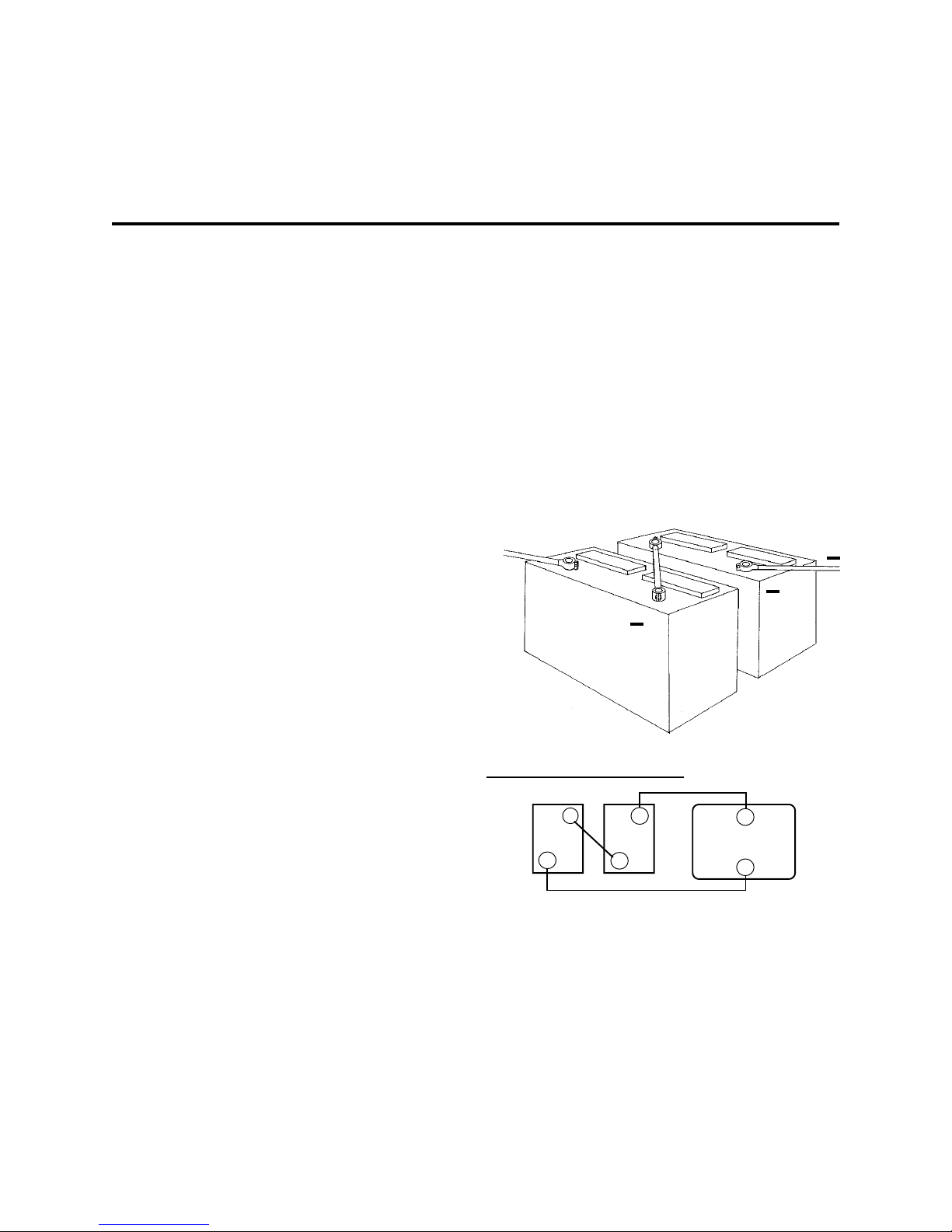
Connecting two batteries in series will
double the voltage of the battery bank. For
instance, two 6 volt batteries connected in
series will produce 12 volts. The Amp-hour
capacity of the battery bank will be the same
as each individual battery. Example, two 6 volt
220 Amp-hour batteries in series will produce
one 12 volt 220 Amp-hour battery bank.
+
+
+
SeriesSeries
Series
SeriesSeries
Series Series
Series Increase Voltage
Series Series
+
6V
_
EACH BATTERY
CAP ACITY:
220
AMP-HOURS
@ 6 VDC
_
6V
+
+
12V INVERTER
_
T OT AL B A TTER Y
BANK CAPACITY :
220
AMP-HOURS
@ 12 VDC
12
Part No. 90-0123-00
Libertycombi.p65 11/05/99
Page 13
ParallelParallel
Parallel
ParallelParallel
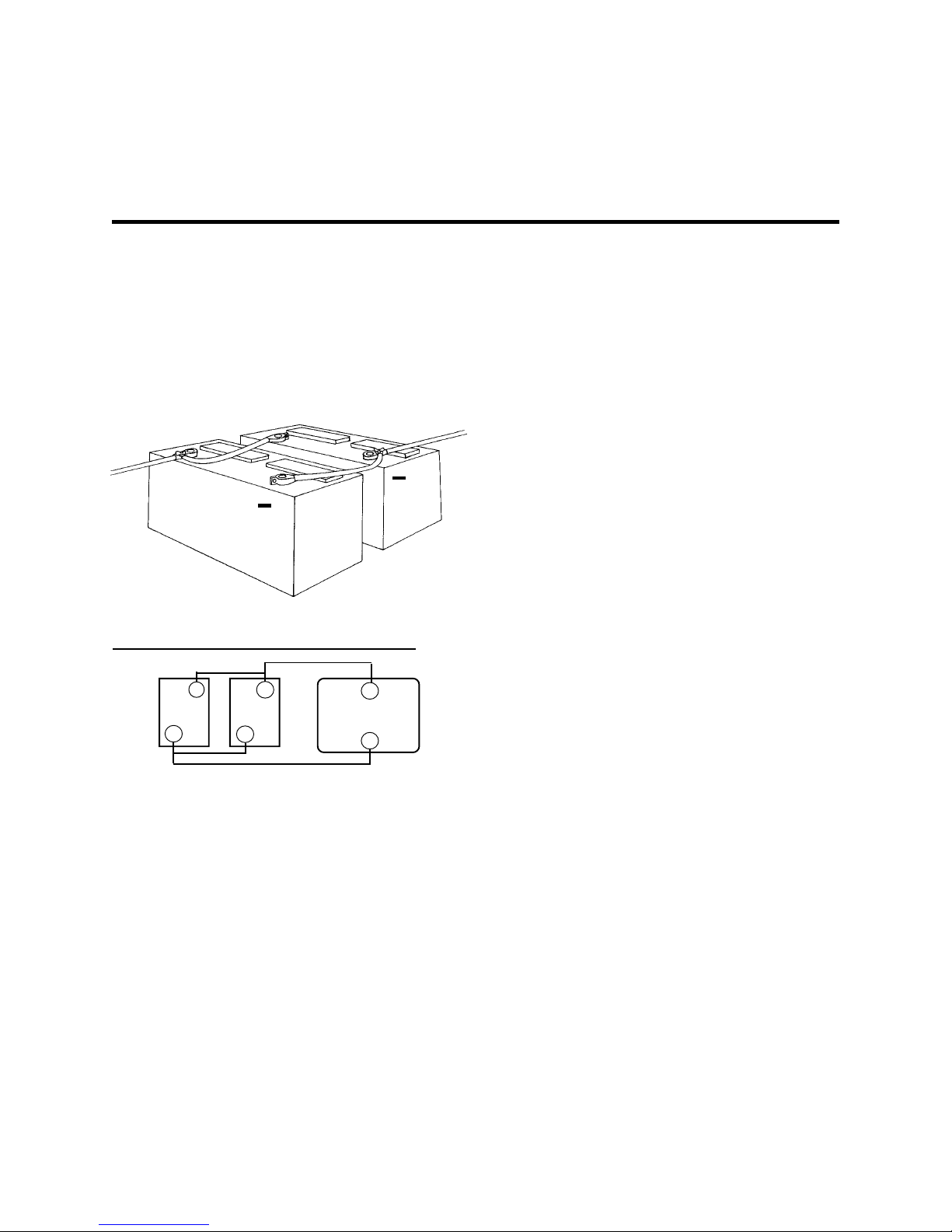
Connecting two batteries in parallel will
double the Amp-hour rating of the battery bank,
while the voltage will be the same as each
individual battery. Example, two 12 volt 105
Amp-hour batteries in parallel will produce one
12 volt 210 Amp-hour battery bank.
+
+
ParallelParallel
Parallel
ParallelParallel
Parallel Parallel
Parallel Increase Amp-hour Capacity
Parallel Parallel
+
12V
_
EACH BATTERY
CAP ACITY:
105
AMP-HOURS
@ 12 VDC
12V
_
+
+
1
2V INVERTER
_
T OT AL B A TTER Y
BANK CAPACITY :
210
AMP-HOURS
@ 12 VDC
BABA
BA
BABA
Note: It is not advisable to connect
batteries of different case sizes or Amp-hour
ratings in the same battery bank.
Always use properly sized wire andAlways use properly sized wire and
Always use properly sized wire and
Always use properly sized wire andAlways use properly sized wire and
terminals for your interconnecting batteryterminals for your interconnecting battery
terminals for your interconnecting battery
terminals for your interconnecting batteryterminals for your interconnecting battery
cables. For size information refer to NECcables. For size information refer to NEC
cables. For size information refer to NEC
cables. For size information refer to NECcables. For size information refer to NEC
requirements or contact your localrequirements or contact your local
requirements or contact your local
requirements or contact your localrequirements or contact your local
electrician.electrician.
electrician.
electrician.electrician.
BABA
TTERTTER
YY
BA
TTER
BABA
TTERTTER
Amp-hours. The Amp-hour rating is based on
a 20-hour discharge rate, therefore, a 100
Amp-hour battery can deliver 5 Amps for 20
hours. If the discharge rate is greater than 5
Amps, the available Amp-hours are decreased. For example, if the load is increased
to 100 Amps, only about 45 Amp-hours will be
available at this rate of discharge.
about 80% of capacity before damage occurs.
Shallow cycling will result in much longer
battery life. Calculating a battery bank size
based on 50% discharge cycling is generally
considered to be a good compromise between
long battery life and size.
BANK RA BANK RA
Y
BANK RA
YY
BANK RA BANK RA
Deep-cycle batteries are usually rated in
Deep-cycle batteries can be discharged
TTERIESTTERIES
TTERIES
TTERIESTTERIES
TINGS TINGS
TINGS
TINGS TINGS
AND SIZINGAND SIZING
AND SIZING
AND SIZINGAND SIZING
Only similar batteries should beOnly similar batteries should be
Only similar batteries should be
Only similar batteries should beOnly similar batteries should be
connected together in one bank. connected together in one bank.
connected together in one bank. Do no t
connected together in one bank. connected together in one bank.
connect old and new batteries together or wet
and gel cell batteries together. In the above
drawing, the load is connected to the positive
terminal of the first battery and the negative
terminal of the last battery. This practice helps
to balance the battery bank and is called
cross-connecting
Part No. 90-0123-00
Libertycombi.p65 11/05/99
the battery bank.
13
Page 14
BABA
BA
BABA
TTERIESTTERIES
TTERIES
TTERIESTTERIES
To achieve
50% cycling you should
calculate your Amp-hour consumption
between charging cycles and use a battery
bank with twice that capacity**. Each AC
appliance or tool has a rating plate on it and will
be rated in either AC Am ps o r W atts or AC VA
( Volt-Amps) apparent power. To calculate Amphour consumption, use one of the formulas to
the right to calculate the DC Amp-hour draw
for a 12 volt system.
Calculate the Amp-hours for every AC
appliance or tool that will be operated on the
inverter. This will provide the total number of
Amp-hours used between recharges. Size the
battery bank using this number as a guideline.
A good rule to follow is to size the battery bank
a minimum of 2 times larger than the
total Amp-hour load requirement. Plan on
recharging when 50% discharged.
**Batteries are typically charged to 85% of full
charge when charging with alternators without 3-stage
regulators.
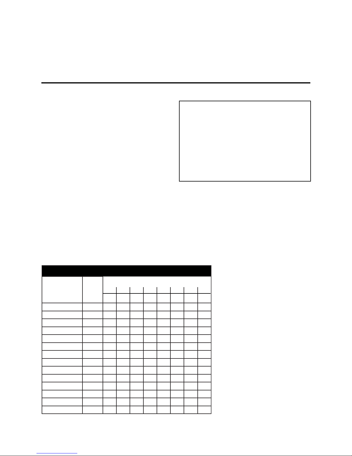
noitpmusnoCrewoPlacipyT
ecnailppA
VTroloC"310533.1248212369
VTroloC"9100166.248614246291
RCV0533.1248212369
pmaL00166.248614246291
rednelB0032621
retupmoCpotpaL0533.1248
norIgnilruC0533.12
llirDrewoP8/30053.30102
*rekamecI0026.22.54.016.516.142.38
rekaMeeffoC00016.6020408061
*rotaregirfeR'uc3051248212369
*rotaregirfeR'uc02057122448621633276
evaworciMtcapmoC0575510306021081
evaworciMeziSlluF0051010306021042063
muucaV00113.7224488671462
lacipyT
egattaW
.niM5.niM51.niM03.rH1.rH2.rH3.rH8.rH42
14
AMP-HOUR CONSUMPTION FORMULASAMP-HOUR CONSUMPTION FORMULAS
AMP-HOUR CONSUMPTION FORMULAS
AMP-HOUR CONSUMPTION FORMULASAMP-HOUR CONSUMPTION FORMULAS
(AC Amps x 10) x 1.1 x hours of(AC Amps x 10) x 1.1 x hours of
(AC Amps x 10) x 1.1 x hours of
(AC Amps x 10) x 1.1 x hours of(AC Amps x 10) x 1.1 x hours of
operation = DC Amp-hoursoperation = DC Amp-hours
operation = DC Amp-hours
operation = DC Amp-hoursoperation = DC Amp-hours
(W(W
atts/ DC Vatts/ DC V
(W
atts/ DC V
(W(W
atts/ DC Vatts/ DC V
operation = DC Amp-hoursoperation = DC Amp-hours
operation = DC Amp-hours
operation = DC Amp-hoursoperation = DC Amp-hours
(AC V(AC V
A/ DC VA/ DC V
(AC V
A/ DC V
(AC V(AC V
A/ DC VA/ DC V
operation = DC Amp-hoursoperation = DC Amp-hours
operation = DC Amp-hours
operation = DC Amp-hoursoperation = DC Amp-hours
oltage) x 1.1 x hours ofoltage) x 1.1 x hours of
oltage) x 1.1 x hours of
oltage) x 1.1 x hours ofoltage) x 1.1 x hours of
oltage) x 1.1 x hours ofoltage) x 1.1 x hours of
oltage) x 1.1 x hours of
oltage) x 1.1 x hours ofoltage) x 1.1 x hours of
DC Voltage is 12, 24 or 32 depending on
your system.
In all formulas, 1.1 is the correction factor for
inverter efficiency.
TT
ypical Power Consumptlonypical Power Consumptlon
T
ypical Power Consumptlon
TT
ypical Power Consumptlonypical Power Consumptlon
The chart identifies typical power
consumption for common AC loads. Use it as
a guide when identifying your power
requirements.
Many electric motors have
momentary starting requirements well above their operational rating. Start up watts are
sruoHpmA/semiTnuRecnailppA
listed where appropriate.
Individual styles and brands of
appliances may vary.
If using the same battery
bank for the inverter and other
DC loads, be sure to consider
the power consumption of the
DC loads when sizing the
battery bank.
NOTENOTE
NOTE Certain laser printers, breadmakers,
NOTENOTE
digital clocks and appliance/tool chargers
.semitnursuounitnocsuoiravnodesab)CDtlov21@(desusruohpmAlatotehtstneserperxobhcaenirebmuN
.elycytud-3/1agnisudetaluclacyllacipytsinoitaregirferetoN*
may not operate on modified sine wave.
Part No. 90-0123-00
Libertycombi.p65 11/05/99
Page 15

BABA
BA
BABA
Battery ChargingBattery Charging
Battery Charging
Battery ChargingBattery Charging
Completely charging wet cell deep-cycle
batteries requires the battery voltage to be
raised beyond what is known as the gassing
point. This is the voltage at which the battery
begins to bubble and gas is given off. If
charging stops short of this point, sulfate is left
on the plates and deterioration of the battery
begins. The gassing point will vary with battery
temperature.
At 77 degrees F, the gassing point of a 12
volt battery is about 14.0 volts.
AGM and Gel cell batteries must not be
charged to their gassing point. In fact, high
voltage charging which gasses these batteries
is harmful to them. They typically require a
lower bulk charge voltage and a higher float
voltage than wet cell batteries. Consult the
battery manufacturer for specifications.
TTERTTER
TTER
TTERTTER
Freedom Battery ChargersFreedom Battery Chargers
Freedom Battery Chargers
Freedom Battery ChargersFreedom Battery Chargers
Freedom battery chargers are designed
to overcome the limitations of conventional
chargers by utilizing 3 distinct charge stages,
each designed for optimal charging of wet, gel
cell and AGM deep-cycle batteries. Battery
type selection is made on the front panel of the
inverter/charger or through the Remote Control
Panel or a Link Instrumentation. For more
information on battery type selection, see page
7 or refer to the Remote Control Panel manual.
YY
CHARGING CHARGING
Y
CHARGING
YY
CHARGING CHARGING
Part No. 90-0123-00
Libertycombi.p65 11/05/99
15
Page 16

BABA
BA
BABA
TTERTTER
TTER
TTERTTER
YY
CHARGING CHARGING
Y
CHARGING
YY
CHARGING CHARGING
NOTE: Freedom battery chargers are ON
whenever AC power is connected to the
charger input. The charger can be turned OFF
using the CHARGE switch on the front of the
unit. This sequence will occur each time
external AC power is available. The charger
can be turned ON/OFF using the Remote
Control Panel or Link Instrumentation.
Each time the battery charger is engaged,
the 3-stage charger proceeds automatically,
resulting in an efficient complete charge and
safe battery maintenance. Use of the Remote
Control Panel or Link Instrument provides the
ability to periodically apply an equalizing
charge.
Refer to Remote Control Panel or the
Link Instrument Owner ’s Manual for more
information.
16
The battery charger stages are:The battery charger stages are:
The battery charger stages are:
The battery charger stages are:The battery charger stages are:
Stage 1 - Stage 1 -
Stage 1 -
Stage 1 - Stage 1 charge stage most of the energy that has been
consumed during discharge is returned to the
battery bank. This phase is engaged as soon
as the battery charger is activated. Full rated
charger current is delivered to the battery bank
until the acceptance charge voltage limit is
reached. This results in a relatively rapid recharge.
Generally, a wet cell battery bank should
not be charged at a rate which exceeds 25% of
its capacity.
Bulk ChargeBulk Charge
Bulk Charge
Bulk ChargeBulk Charge
During the bulk
Part No. 90-0123-00
Libertycombi.p65 11/05/99
Page 17

BABA
BA
BABA
TTERTTER
TTER
TTERTTER
YY
CHARGING CHARGING
Y
CHARGING
YY
CHARGING CHARGING
Gel cell and Advanced AGM batteries can
accept a higher rate of charge. Consult the
manufacturer for specifications.
Stage Stage
Stage
Stage Stage
acceptance stage immediately follows the bulk
charge stage. During this stage the
battery voltage is held constant at the bulk
charge voltage limit and the current gradually
ramps down. During this stage the battery is
accepting its final amount of charge current
and the last
removed.
The acceptance stage lasts until the
charge current reaches the transition point. A
timer will terminate the acceptance stage if this
current level is not reached.
ACCEPTACCEPT
ACCEPT
ACCEPTACCEPT
AC Source Manager20AC Source Manager20
AC Source Manager20
AC Source Manager20AC Source Manager20
AC Source Manager25AC Source Manager25
AC Source Manager25
AC Source Manager25AC Source Manager25
AC Source Manager30AC Source Manager30
AC Source Manager30
AC Source Manager30AC Source Manager30
Maximum acceptance time is 1 hour for
wet and AGM cells and 3 hours for gel cells.
Gel cell acceptance time can be longer
because they are less likely to gas. Expect wet
cell batteries to gas somewhat during
acceptance, this is a necessary part of the
charging process.
2 - Acceptance Charge2 - Acceptance Charge
2 - Acceptance Charge
2 - Acceptance Charge2 - Acceptance Charge
of the sulfate on the plates is
ANCE TANCE T
ANCE T
ANCE TANCE T
O FLOAO FLOA
O FLOA
O FLOAO FLOA
T TRANSITION POINTST TRANSITION POINTS
T TRANSITION POINTS
T TRANSITION POINTST TRANSITION POINTS
15 Ampere DC15 Ampere DC
15 Ampere DC
15 Ampere DC15 Ampere DC
15 Ampere DC15 Ampere DC
15 Ampere DC
15 Ampere DC15 Ampere DC
15 Ampere DC15 Ampere DC
15 Ampere DC
15 Ampere DC15 Ampere DC
The
The float charge stage holds the battery
voltage constant at a preset lower level, where
it is safe for long term battery maintenance.
During the float charge stage, the full output
current of the battery charger is available to
operate any DC appliances that may be on the
system, while constantly maintaining the float
charge voltage.
The battery charger remains in the float
charge stage indefinitely until the charger is
disconnected from incoming AC power or
turned OFF on the unit or with the Remote
Control Panel or Link Instrumentation.
Stage 4 - Stage 4 -
Stage 4 -
Stage 4 - Stage 4 only battery charger stage which is not
engaged automatically. It must be manually
initiated each time. Applying an equalizing
charge is possible only with a Remote Control
Panel or Link Instrument.
Periodic equalizing is recommended by
most wet cell deep-cycle battery manufacturers. There are no firm rules for how
often an equalizing charge should be applied.
Follow the battery manufacturer ’s recommendations for equalizing.
Equalizing ChargeEqualizing Charge
Equalizing Charge
Equalizing ChargeEqualizing Charge
This is the
NOTE: The acceptance stage timer is not
used when Link Instruments control the
charger. Refer to the Link Owner ’ s Manual.
Stage 3Stage 3
Stage 3
Stage 3Stage 3
acceptance stage is terminated, either
because the charge current ramped down to
the transition point or the timer engaged, the
charge current will shut off. The unit monitors
the battery voltage while it drifts down from the
acceptance charge voltage limit. When it
reaches the float voltage set point, the float
charge stage is engaged.
Part No. 90-0123-00
Libertycombi.p65 11/05/99
- Float Charge - Float Charge
- Float Charge
- Float Charge - Float Charge
When the
17
Page 18

BABA
BA
BABA
cycle. The cycle can be ended early by interrupting the AC power to the charger at any
time during the cycle. Equalizing should only
be engaged after the batteries have been fully
charged by a normal battery charging cycle.
voltage will increase to the equalize voltage.
This will cause the battery bank to gas
profusely and will accomplish the following:
1. Removal of residual sulfate.1. Removal of residual sulfate.
1. Removal of residual sulfate. Each time a
1. Removal of residual sulfate.1. Removal of residual sulfate.
battery is cycled (discharged and charged), a
small amount of sulfate is left on the plates.
Over time, this gradual build-up of sulfate will
compromise the performance of the battery.
By applying an equalizing charge, the sulfate is
returned back to the electrolyte, raising the
specific gravity and fully exposing the active
material of the plates.
TTERTTER
TTER
TTERTTER
The equalizing charge is a timed, 8-hour
During this equalizing stage, the battery
YY
CHARGING CHARGING
Y
CHARGING
YY
CHARGING CHARGING
Bring all cells to the same potential. Bring all cells to the same potential.
2.
Bring all cells to the same potential. A ll
Bring all cells to the same potential. Bring all cells to the same potential.
lead-acid batteries are made up of individual 2
volt cells. As the battery bank is cycled, slight
differences in the cells result in different cell
voltages, affecting the overall charge
effectiveness. Equalizing brings all cells to the
same voltage and the electrolyte in each cell to
the same specific gravity.
Mixing up of the electrolyte. Mixing up of the electrolyte.
3.
Mixing up of the electrolyte. Electrolyte in
Mixing up of the electrolyte. Mixing up of the electrolyte.
battery cells tend to separate into layers of acid
and water. The vigorous bubbling action of the
battery during equalizing serves to physically
mix the electrolyte. Refer to the Remote
Control Panel and Link Owner ’s Manuals for
additional cautions on equalizing.
Note: Do not equalize gel cell batteries.
18
Part No. 90-0123-00
Libertycombi.p65 11/05/99
Page 19

WW
ARNINGSARNINGS
W
ARNINGS
WW
ARNINGSARNINGS
1. Do not equalize gel cell batteries.1. Do not equalize gel cell batteries.
1. Do not equalize gel cell batteries.
1. Do not equalize gel cell batteries.1. Do not equalize gel cell batteries.
Check remote default settings.
2. Always monitor the equalize charge2. Always monitor the equalize charge
2. Always monitor the equalize charge
2. Always monitor the equalize charge2. Always monitor the equalize charge
cycle. cycle.
cycle. Provide proper ventilation for
cycle. cycle.
battery fumes. Do not allow any sparks
during equalizing. If one or more cells
begin to overflow, terminate the equalize
cycle.
3. Check the battery electrolyte both3. Check the battery electrolyte both
3. Check the battery electrolyte both
3. Check the battery electrolyte both3. Check the battery electrolyte both
before and after the equalizing charge.before and after the equalizing charge.
before and after the equalizing charge.
before and after the equalizing charge.before and after the equalizing charge.
Do not expose the battery plates to air.
Leave the battery caps on while
equalizing. Top off after equalizing.
4. Remove all loads from the DC4. Remove all loads from the DC
4. Remove all loads from the DC
4. Remove all loads from the DC4. Remove all loads from the DC
system before equalizing. system before equalizing.
system before equalizing. Some DC
system before equalizing. system before equalizing.
loads may not tolerate the high charge
voltage.
BABA
BA
BABA
TTERTTER
TTER
TTERTTER
YY
CHARGING CHARGING
Y
CHARGING
YY
CHARGING CHARGING
5. With the Remote Control Panel 5. With the Remote Control Panel
5. With the Remote Control Panel
5. With the Remote Control Panel 5. With the Remote Control Panel
battery state-of-charge LEDs sequence
during equalizing. When the equalization
cycle is complete, the charge automatically goes to float and the green float LED
battery status light is on.
InstrumentationInstrumentation
Instrumentation, the red charge LED
InstrumentationInstrumentation
flashes during the equalizing cycle. When
the equalization cycle is complete, the
charger automatically goes to float and the
green float LED is illuminated.
Part No. 90-0123-00
Libertycombi.p65 11/05/99
With LinkWith Link
With Link
With LinkWith Link
the
19
Page 20

BABA
TTERTTER
BA
TTER
BABA
TTERTTER
PMET 0EPYT 1EPYT 2EPYT 3EPYT
F° C°TPECCATAOLFTPECCATAOLFTPECCATAOLFTPECCATAOLF
021 945.215.210.310.310.310.319.219.21
011 346.317.215.310.310.414.319.319.21
001 838.319.217.312.311.415.310.410.31
09 230.411.318.313.312.416.311.411.31
08 722.413.310.415.313.417.312.412.31
**07 **124.415.311.416.314.418.313.413.31
06 616.417.313.418.315.419.314.414.31
05 018.419.314.419.316.410.415.415.31
YY
CHARGER VOL CHARGER VOL
Y
CHARGER VOL
YY
CHARGER VOL CHARGER VOL
lleCteW *1leG *2leG MGA
TT
AGE SETTINGSAGE SETTINGS
T
AGE SETTINGS
TT
AGE SETTINGSAGE SETTINGS
04 50.511.416.411.417.411.416.416.31
03 1-2.513.417.412.418.412.417.417.31
* There are two gel battery settings. Check with the battery manufacturer to determine the
proper setting for your batteries. Usually, Gel 1 is for long battery life; Gel 2 is for rapid charging.
**Default setting when the temperature sensor is not connected.
20
Part No. 90-0123-00
Libertycombi.p65 11/05/99
Page 21
INSTINST
INST
INSTINST
CAUTIONCAUTION
CAUTION This equipment is
CAUTIONCAUTION
protected protected
protected and employs components that can
protected protected
produce arcs or sparks. To reduce the risk of
fire or
unvented compartments containingunvented compartments containing
unvented compartments containing
unvented compartments containingunvented compartments containing
batteries or flammable gasses batteries or flammable gasses
batteries or flammable gasses o r areas in
batteries or flammable gasses batteries or flammable gasses
which ignition-protected equipment is required.
CAUTIONCAUTION
CAUTION To reduce the risk of electric shock
CAUTIONCAUTION
and prevent premature failure due to corrosion,
do not mount where exposed to rain,do not mount where exposed to rain,
do not mount where exposed to rain,
do not mount where exposed to rain,do not mount where exposed to rain,
dripping or spraydripping or spray
dripping or spray
dripping or spraydripping or spray
CAUTION CAUTION
CAUTION To reduce the risk of fire, do not
CAUTION CAUTION
obstruct ventilation openings. Do not mount
in a zero clearance compartment,
overheating may result.
explosions, do not install inexplosions, do not install in
explosions, do not install in
explosions, do not install inexplosions, do not install in
WW
ARNINGARNING
W
ARNING
WW
ARNINGARNING
For continued protection against risk of
electric shock, use only the ground-fault
circuit interrupter (GFCI) type receptacles
detailed in this manual. Other types may
fail to operate properly when connected to
this inverter, resulting in a potential shock
hazard.
..
.
..
ALLAALLA
ALLA
ALLAALLA
not ignitionnot ignition
not ignition
not ignitionnot ignition
TION PRECAUTIONSTION PRECAUTIONS
TION PRECAUTIONS
TION PRECAUTIONSTION PRECAUTIONS
Confirm that your shipping carton contains:Confirm that your shipping carton contains:
Confirm that your shipping carton contains:
Confirm that your shipping carton contains:Confirm that your shipping carton contains:
• Inverter/Charger
• TSC temperature sensor with 15’ cable
• Owners Manual
• Warranty Card
• Jumper for AUX Switch (only used
Remote Control Panel or Link Instrument)
• Wire Nuts
TT
ypical Typical T
T
ypical T
TT
ypical Typical T
Flathead and Phillips Screwdrivers
Allen (Hex) Screwdriver (1/8”)
Wrench for connecting battery cables (9/16”)
Wire Cutters
Wire Strippers
Misc. assortment of wire ties and connectors
Accessories Needed for InstallationAccessories Needed for Installation
Accessories Needed for Installation
Accessories Needed for InstallationAccessories Needed for Installation
Fuse - UL Listed DC Rated slow blow fuse as
required by NEC
Electrical wire (10 gauge) for AC input wiring.
Consult NEC for proper size for output wiring.
Battery Cables 1- Positive, 1-Negative
Consult NEC for proper size
DC fuse cable
Mounting Screws (4)
ools Neededools Needed
ools Needed
ools Neededools Needed
without
CAUTIONCAUTION
CAUTION
CAUTIONCAUTION
AC & DC voltage sources are terminatedAC & DC voltage sources are terminated
AC & DC voltage sources are terminated
AC & DC voltage sources are terminatedAC & DC voltage sources are terminated
inside this equipment.inside this equipment.
inside this equipment.
inside this equipment.inside this equipment.
disconnect all inputs and outputs.
Part No. 90-0123-00
Libertycombi.p65 11/05/99
Risk of electrical shock. BothRisk of electrical shock. Both
Risk of electrical shock. Both
Risk of electrical shock. BothRisk of electrical shock. Both
Before servicing
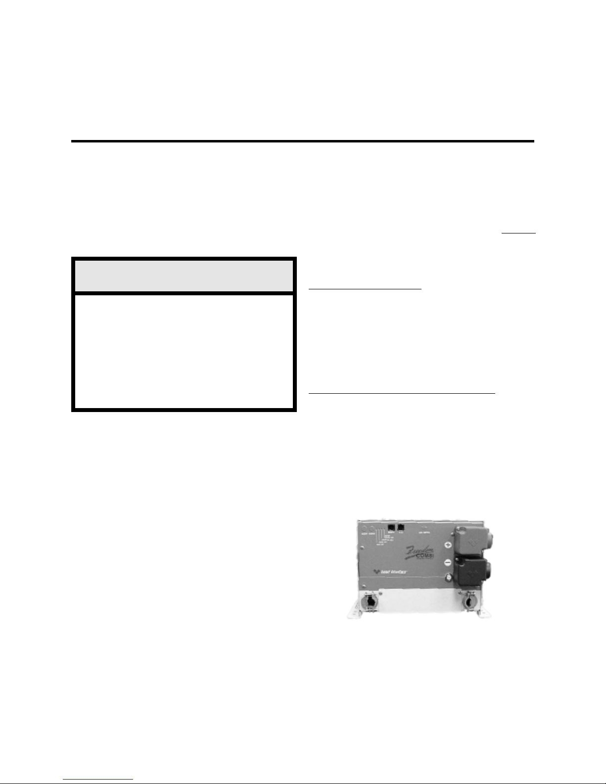
Freedom 20Freedom 20
Freedom 20
Freedom 20Freedom 20
The Freedom 15D and 20D have
dual AC Outputs.
21
Page 22
INSTINST
INST
INSTINST
ALLAALLA
ALLA
ALLAALLA
TIONTION
TION
TIONTION
CAUTION CAUTION
CAUTION
CAUTION CAUTION
remove coverremove cover
remove cover
remove coverremove cover
inside.inside.
inside.
inside.inside.
personnel.
installation in recreational vehicles (RV), and
other applications.
completed by an authorized Heart Interface
technical dealer or experienced electrician.
Key Installation PointsKey Installation Points
Key Installation Points
Key Installation PointsKey Installation Points
1. The unit is designed to mount1. The unit is designed to mount
1. The unit is designed to mount
1. The unit is designed to mount1. The unit is designed to mount
horizontallyhorizontally
horizontally (on a shelf).
horizontallyhorizontally
2. Allow several inches of clearance2. Allow several inches of clearance
2. Allow several inches of clearance around
2. Allow several inches of clearance2. Allow several inches of clearance
the unit to permit a supply of fresh air to the
cooling fan. Do not block any of the vents or
louvers. The thermostat controlled fan pulls air
from outside the unit. It pulls air across the
internal components, particularly the transformer and heat sinks, then out the fan vent.
3.3.
Keep the inverter/charger out of theKeep the inverter/charger out of the
3.
Keep the inverter/charger out of the
3.3.
Keep the inverter/charger out of theKeep the inverter/charger out of the
elements and out of direct contact withelements and out of direct contact with
elements and out of direct contact with
elements and out of direct contact withelements and out of direct contact with
water or spraywater or spray
water or spray
water or spraywater or spray
premature malfunction from corrosion and void
the warranty.
4.4.
Mount the unit as close to the batteriesMount the unit as close to the batteries
4.
Mount the unit as close to the batteries
4.4.
Mount the unit as close to the batteriesMount the unit as close to the batteries
as possible as possible
as possible but not in the presence of
as possible as possible
flammable fumes or in an enclosed battery
compartment.
Risk of electrical shock. Do notRisk of electrical shock. Do not
Risk of electrical shock. Do not
Risk of electrical shock. Do notRisk of electrical shock. Do not
, no user serviceable parts, no user serviceable parts
, no user serviceable parts
, no user serviceable parts, no user serviceable parts
Refer servicing to qualified service
The Freedom Combi is appropriate for
It is recommended that installation be
. .
. Failure to do so may result in
. .
5. Keep the overall length of each battery5. Keep the overall length of each battery
5. Keep the overall length of each battery
5. Keep the overall length of each battery5. Keep the overall length of each battery
cable less than 10 feet. cable less than 10 feet.
cable less than 10 feet. Do not use frame
cable less than 10 feet. cable less than 10 feet.
ground or a ground bonding system as a
current carrying conductor. Run the negative(-)
cable directly to the battery bank. If the positive
(+) and negative (-) cables run parallel to each
other, twist the cables together. This will
minimize the inductive adverse effects of cable
length. Be sure the cable size meets with NEC
requirements for your installation.
6. Make sure all wiring conforms to local6. Make sure all wiring conforms to local
6. Make sure all wiring conforms to local
6. Make sure all wiring conforms to local6. Make sure all wiring conforms to local
and national electrical codes. and national electrical codes.
and national electrical codes. If in doubt,
and national electrical codes. and national electrical codes.
consult with a qualified electrician.
7. T7. T
o meet electrical codes, o meet electrical codes,
7. T
o meet electrical codes, a UL Listed DC
7. T7. T
o meet electrical codes, o meet electrical codes,
Rated slow blow fuse must be installed in the
positive battery cable within 18 inches of the
battery post. This fuse is intended to protect
the battery and cables against a short circuit.
The inverter is protected internally and will not
blow a properly sized fuse.
8. Do not connect the battery until you8. Do not connect the battery until you
8. Do not connect the battery until you
8. Do not connect the battery until you8. Do not connect the battery until you
have read the remainder of the installationhave read the remainder of the installation
have read the remainder of the installation
have read the remainder of the installationhave read the remainder of the installation
section. Observe proper polarity section. Observe proper polarity
section. Observe proper polarity when
section. Observe proper polarity section. Observe proper polarity
connecting batteries. Reverse DC polarity will
result in damage to the unit and will void the
warranty. Use care when making the DC
connections.
WW
ARNINGARNING
W
ARNING
WW
ARNINGARNING
Do not mount the unit in an enclosed
battery compartment. Take precautions to
keep dirt and spray off the unit.
22
WW
ARNINGARNING
W
ARNING
WW
ARNINGARNING
The Freedom Series is not DC reverse
polarity protected. Be very careful to
connect the negative and positive cables
correctly, otherwise damage will result and
the warranty will be void.
Part No. 90-0123-00
Libertycombi.p65 11/05/99
Page 23
9. Do not back-feed the AC output of the9. Do not back-feed the AC output of the
9. Do not back-feed the AC output of the
9. Do not back-feed the AC output of the9. Do not back-feed the AC output of the
inverter with incoming inverter with incoming
inverter with incoming
inverter with incoming inverter with incoming
back-feed occurs when AC power from shore
power or generator is connected to the output
of the inverter. This will damage the inverter
and void the warranty. Remember that
incoming
and never the AC output. Always check for AC
voltage before connecting wires to the AC
output. Do NOT turn the inverter ON until all
AC connections have been made. Backfeeding the inverter voids the warranty.
Do not connect incoming AC from any
source to the AC output of the inverter.
This is known as back-feeding and will
damage the unit and void the warranty.
10. Do not connect the AC input to the AC10. Do not connect the AC input to the AC
10. Do not connect the AC input to the AC
10. Do not connect the AC input to the AC10. Do not connect the AC input to the AC
output.output.
output. This would be equivalent to plugging
output.output.
the battery charger into the inverter. This could
occur if the unit’s AC output is connected to
the entire leg of a circuit breaker panel, then a
circuit breaker on that leg is used to feed the
battery charger input. This will cause the unit
to oscillate ON and OFF when the unit is in
inverter mode.
11
1. 1.
1
1.
11
1. 1.
connectors.connectors.
connectors. The proper battery cable size is
connectors.connectors.
critical. Considerable amperage flows in the
DC circuit. For the Freedom 10 use 2
AWG(for the Freedom 15, 20, 25 2/0 AWG, for
the Freedom 30 3/0 A WG) UL Listed W elding
Cable terminated on each with UL Listed or UL
Recognized ring terminal connectors.For the
terminal, use Thomas & Betts (T&B) part number BAL 2038. Be sure the connectors are attached to the cable using a method approved
by the connector manufacturer. For the con-
AC must be fed only to the AC input
WW
ARNINGARNING
W
ARNING
WW
ARNINGARNING
Always use proper wire andAlways use proper wire and
Always use proper wire and
Always use proper wire andAlways use proper wire and
AC powerAC power
AC power
AC powerAC power
. .
. A
. .
INSTINST
INST
INSTINST
nections to meet all requirements, T&B recommends that each terminal be crimped in two
places with a pressure of 15 tons using a hexagonal die. The T&B die has a code
number of 54. After the crimp is made, the
barrel of the terminal and the first inch of the
cable needs to be covered in UL Listed or UL
Recognized heat shrink tubing. Heart Interface
recommends a 2-inch length of 3M HDT 0800
tubing. Other heat shrink may be used if it is
UL Listed or UL Recognized as long as the
manufacturer’s directions are followed.
12.12.
12. If installing in a system which includes an
12.12.
existing battery charger or AC to DC converter,
make sure these do not operate from themake sure these do not operate from the
make sure these do not operate from the
make sure these do not operate from themake sure these do not operate from the
inverter output inverter output
inverter output
inverter output inverter output
power loop which, due to inefficiencies, will
quickly drain the batteries.
13.13.
13. An Auxiliary Switch port is located on the
13.13.
front panel of the unit, covered by a flap. When
installing the unit for operation without a
Remote Control Panel or Link Instrument, a
jumper must be installed in the Aux Switch
port. The jumper is shipped in a plastic bag
with other installation parts. DO NOT install
the jumper until all cable connections have
been made.
When using a Remote Control Panel orWhen using a Remote Control Panel or
When using a Remote Control Panel or
When using a Remote Control Panel orWhen using a Remote Control Panel or
Link Instrument, the jumper is not used.Link Instrument, the jumper is not used.
Link Instrument, the jumper is not used.
Link Instrument, the jumper is not used.Link Instrument, the jumper is not used.
Auxiliary Switch PortAuxiliary Switch Port
Auxiliary Switch Port
Auxiliary Switch PortAuxiliary Switch Port
ALLAALLA
ALLA
ALLAALLA
AC powerAC power
AC power
AC powerAC power
TIONTION
TION
TIONTION
. .
. This sets up a
. .
JumperJumper
Jumper
JumperJumper
Actual size 3/8”L x 3/16”W
Freedom 20Freedom 20
Freedom 20
Freedom 20Freedom 20
Part No. 90-0123-00
Libertycombi.p65 11/05/99
23
Page 24
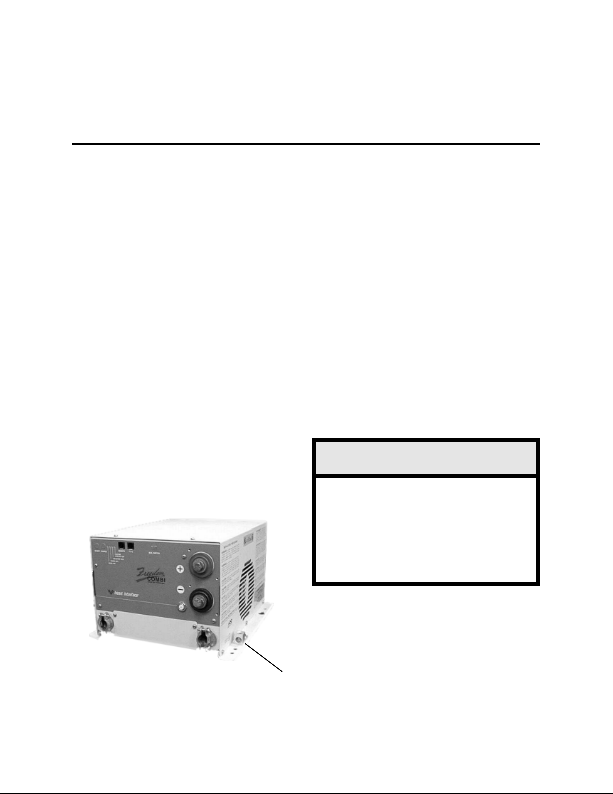
INSTINST
INST
INSTINST
GroundingGrounding
Grounding
GroundingGrounding
For safety purposes, the chassis of the
inverter/charger must be connected to your AC
ground system. Use 8 AWG bare copper or
green insulated wire, strip one end and use a
screwdriver to secure it to the chassis ground
bonding lug on the side of the unit. This wire
will connect to the ground in your AC electrical
system. Make sure the connection is clean and
tight.
The system AC ground bonding terminal
is located on the front of the unit under the
wiring cover at the bottom of the unit. This
connector is for the bare copper or green
ground wires from the AC branch circuit supply
and to the AC loads or distribution panel. It is
important that these AC input and AC output
ground wires connect to the AC ground bus in
the circuit breaker panels.
ALLAALLA
ALLA
ALLAALLA
TIONTION
TION
TIONTION
Note: The battery cables are notNote: The battery cables are not
Note: The battery cables are not
Note: The battery cables are notNote: The battery cables are not
connected to the AC ground strip or to theconnected to the AC ground strip or to the
connected to the AC ground strip or to the
connected to the AC ground strip or to theconnected to the AC ground strip or to the
chassis lug of the unit.chassis lug of the unit.
chassis lug of the unit.
chassis lug of the unit.chassis lug of the unit.
Neutral BondingNeutral Bonding
Neutral Bonding
Neutral BondingNeutral Bonding
For safety purposes and NEC code
requirements, the Freedom Combi unit
internally bonds the AC output neutral (white)
to the AC output ground (green), when the unit
is OFF or in the inverter mode. When
incoming AC power is applied and the transfer
switch is engaged, the internal neutral-toground bond is automatically lifted.
When external AC power is applied, the
grounding system is connected to the source
power ground, where neutral and earth ground
are bonded together. This technique insures
safety in all conditions and conforms to the
requirements of the NEC.
Some installations require heavier
grounding wire. Conform to local and national
electrical codes.
More information on grounding can be
found in the National Electrical Code and
local electrical codes.
Ground LugGround Lug
Ground Lug
Ground LugGround Lug
WW
ARNINGARNING
W
ARNING
WW
ARNINGARNING
Do not connect incoming AC from any
source to the AC output of the inverter/
charger. This is known as back-feeding
and will damage the unit and void the
warranty. The Over Temp/Overload and
Low Battery LEDs will be blinking rapidly if
this condition exists.
24
Part No. 90-0123-00
Libertycombi.p65 11/05/99
Page 25
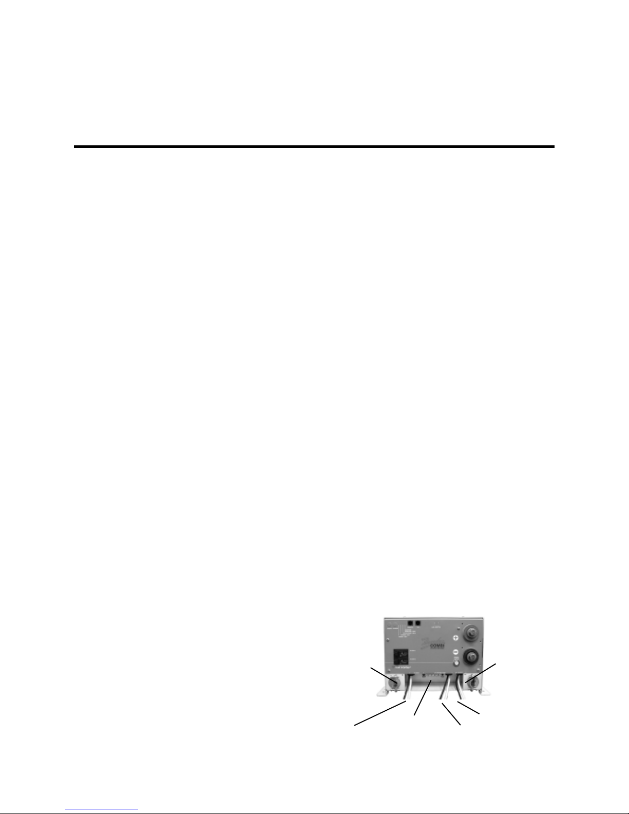
INSTINST
INST
INSTINST
ALLAALLA
ALLA
ALLAALLA
TIONTION
TION
TIONTION
AC WiringAC Wiring
AC Wiring
AC WiringAC Wiring
The AC wires route through the strain
relief mounted in holes on the front of the unit.
Use a screwdriver to remove the screws
which secure the AC wiring compartment
cover plate. Depending upon which model you
have, there can be one or two AC inputs and
one or two AC outputs within the AC wiring
compartment. The labeling for the pigtails is on
the front of the unit and is visible when the
cover plate is removed. Note: Green wires are
connected to the AC Ground Strip.
Black . . . . . . . . . . . . . . . . . Hot or LineBlack . . . . . . . . . . . . . . . . . Hot or Line
Black . . . . . . . . . . . . . . . . . Hot or Line
Black . . . . . . . . . . . . . . . . . Hot or LineBlack . . . . . . . . . . . . . . . . . Hot or Line
White . . . . . . . . . . . . . . . . . N eutralWhite . . . . . . . . . . . . . . . . . N eutral
White . . . . . . . . . . . . . . . . . N eutral
White . . . . . . . . . . . . . . . . . N eutralWhite . . . . . . . . . . . . . . . . . N eutral
Conventional metal strain reliefs are
provided. These can be replaced with plastic
strain reliefs for additional corrosion resistance
or 3/4 inch conduit fittings if the wiring will be
routed through a conduit.
Appropriate wire gauges must be used
throughout the installation. Refer to NEC
specifications.
AC Input:AC Input:
AC Input: All inputs from other AC
AC Input:AC Input:
sources must be protected by branch circuit
rated circuit breakers.
In the United States, no additional circuit
breakers are required between the inverter/
charger and the loads if the service to the
inverter/charger is protected by a 20 ampere
branch circuit rated breaker. This also applies
to Dual Input models where the inputs may be
20 amperes each. In Canada, 15 ampere
branch circuit(s) maximum shall provide the
service.
rated circuit breakers will be required between
the inverter/charger and the loads.
Feed one or two 3 conductor AC input
wire(s) through the strain relief and into the AC
wiring compartment. Allow 6 inches of
individual insulated black, white and green wire
to work with. Strip 1/2 inch of insulation off
each conductor and connect to the pigtails:
Black to Black, White to White, and Green to
AC Ground Strip.
Use the wire nuts provided to make the
wire connections. You may chose to use butt
splices (not included) to make the wire
connections.
AC Output:AC Output:
AC Output: Depending on the model you
AC Output:AC Output:
have, feed one or two 3 conductor AC output
wire groups for the two branch circuit loads
through its strain relief. Remember to allow 6
inches of individual insulated black, white and
green wire to work with. Strip 1/2 inch of
insulation off each conductor and connect to
the pigtails: Black to Black, White to White,
and Green to AC Ground Strip.
Tug firmly on each connection to make
sure they are secure. Later, if the unit is not
operating properly, check these connections
first. Carefully tuck the wires into the AC wiring
compartment. Replace the cover plate.
Dual AC OutputDual AC Output
Dual AC Output
Dual AC OutputDual AC Output
STRAINSTRAIN
STRAIN
STRAINSTRAIN
STRAIN
STRAINSTRAIN
RELIEFRELIEF
RELIEF
RELIEFRELIEF
STRAINSTRAIN
RELIEFRELIEF
RELIEF
RELIEFRELIEF
If a 30 ampere service supplies the
inverter/charger, additional 20 ampere (15
ampere in Canada) maximum branch circuit
Part No. 90-0123-00
Libertycombi.p65 11/05/99
INPUTINPUT
INPUT
INPUTINPUT
AC GROUNDAC GROUND
AC GROUND
AC GROUNDAC GROUND
STRIPSTRIP
STRIP
STRIPSTRIP
AC OUTPUT 2AC OUTPUT 2
AC OUTPUT 2
AC OUTPUT 2AC OUTPUT 2
AC OUTPUT 1AC OUTPUT 1
AC OUTPUT 1
AC OUTPUT 1AC OUTPUT 1
25
Page 26
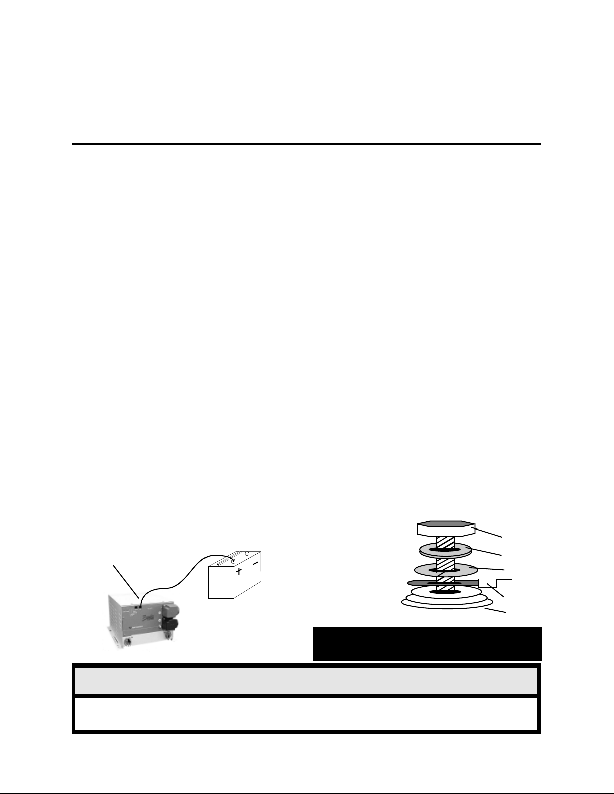
INSTINST
INST
INSTINST
ALLAALLA
ALLA
ALLAALLA
TIONTION
TION
TIONTION
Ground Fault Circult InterruptersGround Fault Circult Interrupters
Ground Fault Circult Interrupters
Ground Fault Circult InterruptersGround Fault Circult Interrupters
To conform to NEC regulations, certain
branch circuits must be equipped with a
Ground Fault Circuit Interrupter (GFCI). Please
consult the code or a qualified electrician for
details. Any such branch circuits must be
protected by a brand rated circuit breaker
consistent with the GFCI rating. Underwriters
Laboratories has tested the following GFCI,
and its use is recommended. Receptacle
Type:
Pass & SeymourPass & Seymour
Pass & Seymour
Pass & SeymourPass & Seymour
Catalog Number 1591Catalog Number 1591
Catalog Number 1591
Catalog Number 1591Catalog Number 1591
Rated: 15 Rated: 15
Rated: 15
Rated: 15 Rated: 15
Remote Control WiringRemote Control Wiring
Remote Control Wiring
Remote Control WiringRemote Control Wiring
If installing a remote panel, route the
remote cable and connect to the Remote jack
on the front of the unit. Refer to the Remote
Control Panel or Link Owner ’s Manual for more
information.
TSC TTSC T
TSC T
TSC TTSC T
Sensitive Charging) sensor, connect the ring
terminal end to the positive battery post,
complete the routing of the RJ11 cable (15 feet
supplied) and connect the plug end to the TSC
jack on the front of the unit
emperature Sensoremperature Sensor
emperature Sensor
emperature Sensoremperature Sensor
If installing the TSC (T emperature
TSC JackTSC Jack
TSC Jack
TSC JackTSC Jack
Amps at 120 VAmps at 120 V
Amps at 120 V
Amps at 120 VAmps at 120 V
RJ1RJ1
1 Cable1 Cable
RJ1
1 Cable
RJ1RJ1
1 Cable1 Cable
olts olts
olts
olts olts
ACAC
AC
ACAC
DC WiringDC Wiring
DC Wiring
DC WiringDC Wiring
DC wiring is generally very simple, the
positive (+, may be red for identification) and
negative (-, may be black or yellow for
identification) cables from the inverter/charger
terminal posts are connected to the house or
auxiliary battery. Connection to the engine
starter battery is not recommended.
High current will pass through the DC
wiring. All wires must be properly sized and
all connections clean and tight. It is
recommended that the battery cable length
does not exceed 10 feet.
Battery cables should be connected to the
inverter/charger before any connections are
made to the battery. Follow the battery
hardware stackup diagram.
• Remove the negative (-) battery cable
cover from the unit and attach the battery
cable. T ighten the battery terminal bolts to a
torque value between 160 inch-pounds and
180 inch--pounds. Replace the cover for the
negative terminal before removing the cover for
the positive terminal.
Battery CableBattery Cable
Battery Cable
Battery CableBattery Cable
Hardware StackupHardware Stackup
Hardware Stackup
Hardware StackupHardware Stackup
DiagramDiagram
Diagram
DiagramDiagram
BoltBolt
Bolt
BoltBolt
Lock WasherLock Washer
Lock Washer
Lock WasherLock Washer
Flat WasherFlat Washer
Flat Washer
Flat WasherFlat Washer
Freedom 20 shown.Freedom 20 shown.
Freedom 20 shown.
Freedom 20 shown.Freedom 20 shown.
Freedom Inverter/Chargers are not protected against DC reverse polarity. Be very careful to connect the
negative and positive cables correctly or damage will result and the warranty will be void.
26
BatteryBattery
Battery
BatteryBattery
WW
ARNINGARNING
W
ARNING
WW
ARNINGARNING
Battery CableBattery Cable
Battery Cable
Battery CableBattery Cable
Inverter/ChargerInverter/Charger
Inverter/Charger
Inverter/ChargerInverter/Charger
CAUTION Improper stackup may result inCAUTION Improper stackup may result in
CAUTION Improper stackup may result in
CAUTION Improper stackup may result inCAUTION Improper stackup may result in
excessive heat and damage to the unit.excessive heat and damage to the unit.
excessive heat and damage to the unit.
excessive heat and damage to the unit.excessive heat and damage to the unit.
Part No. 90-0123-00
Libertycombi.p65 11/05/99
Page 27
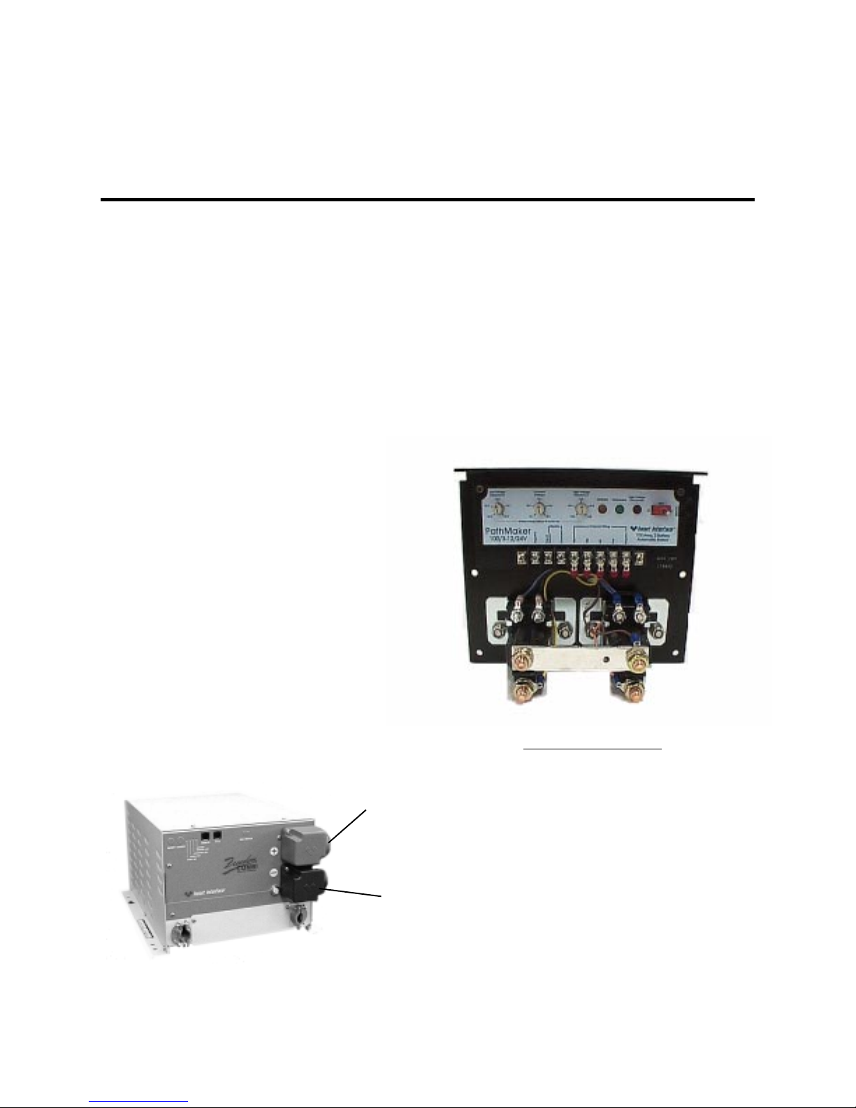
INSTINST
INST
INSTINST
ALLAALLA
ALLA
ALLAALLA
TIONTION
TION
TIONTION
• Remove the positive (+) battery cable
terminal cover from the unit and attach the
battery cable. T ighten the battery terminal bolts
to a torque value between 160 inch-pounds
and 180 inch-pounds. Replace the cover for
the positive terminal.
The negative (-) cable should be
connected directly to the negative post of the
house or auxiliary battery bank or the ground
side of a current shunt. Tighten securely.
The positive (+) battery cable must be
fused and connected to the positive post of the
house or auxiliary battery bank, or through a
selector switch to one or more battery banks.
A spark may be generated when the final
battery connection is made. This is normal; do
not be alarmed. However, do not make the final
connection in the presence of flammable
fumes.
If multiple battery banks are to be
charged, a battery bank selector switch can be
installed, allowing the banks to be charged
either individually or simultaneously. A solenoid
can also be used. The PathMaker Battery
Combiner, b y Heart Interface, may be used to
connect multiple battery banks. The
PathMaker battery combiner is available from
your Heart dealer.
If multiple batteries are used, the
interconnecting jumper cables must be the
same A WG or larger as those connected to
the inverter/charger.
NOTE: If installing in a vehicle, do not use the
vehicle frame as the negative conductor.
POSITIVE (+)POSITIVE (+)
POSITIVE (+)
POSITIVE (+)POSITIVE (+)
(Battery Cable(Battery Cable
(Battery Cable
(Battery Cable(Battery Cable
Cover on)Cover on)
Cover on)
Cover on)Cover on)
NEGANEGA
NEGA
NEGANEGA
(Battery Cable(Battery Cable
(Battery Cable
(Battery Cable(Battery Cable
Freedom 20Freedom 20
Freedom 20
Freedom 20Freedom 20
TIVE (-)TIVE (-)
TIVE (-)
TIVE (-)TIVE (-)
Cover on)Cover on)
Cover on)
Cover on)Cover on)
PathMaker 100, 2 ChannelPathMaker 100, 2 Channel
PathMaker 100, 2 Channel
PathMaker 100, 2 ChannelPathMaker 100, 2 Channel
PathMaker ModelsPathMaker Models
PathMaker Models
PathMaker ModelsPathMaker Models
100 Amp, 2 Channel
100 Amp, 3 Channel
200 Amp, 2 Channel
200 Amp, 3 Channel
27
Part No. 90-0123-00
Libertycombi.p65 11/05/99
Page 28
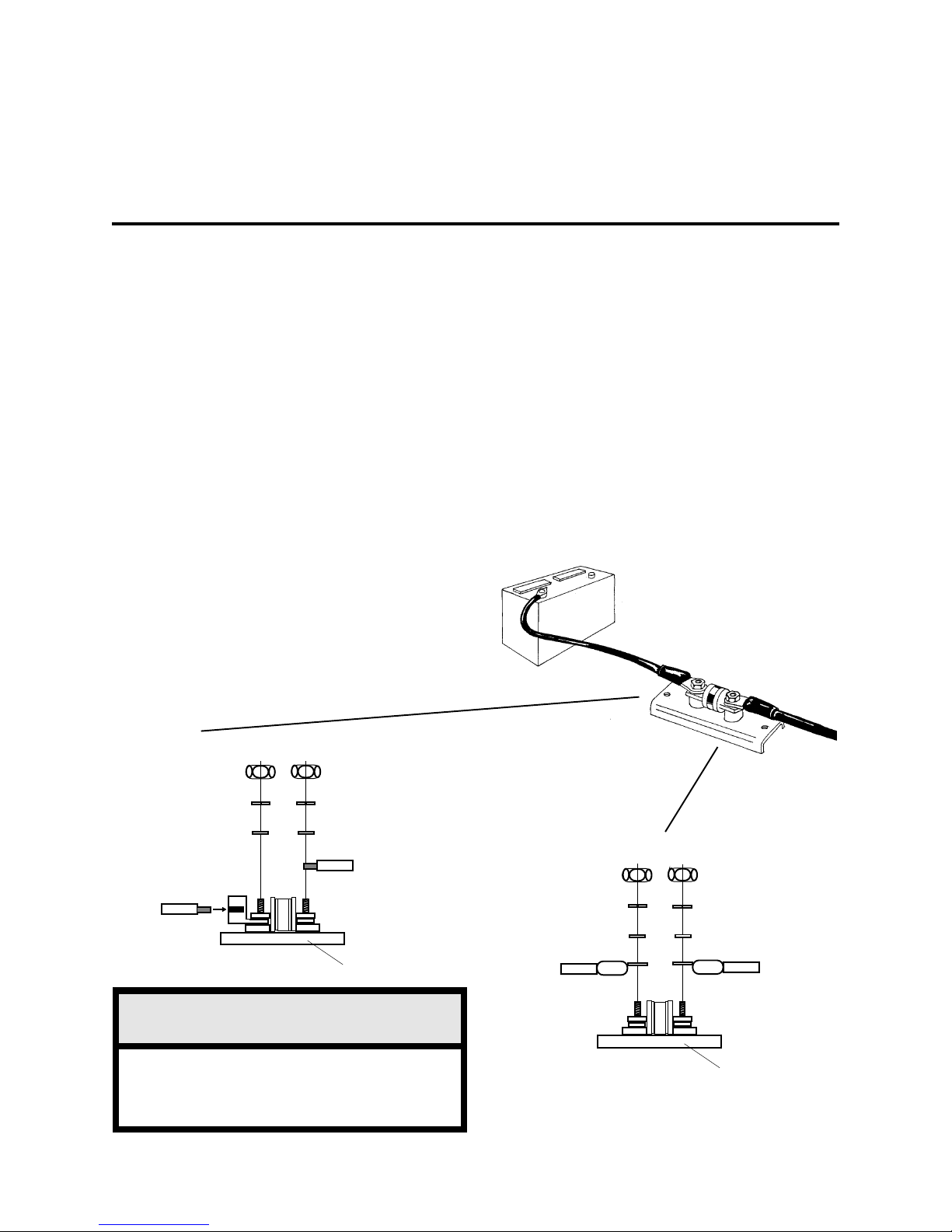
INSTINST
INST
INSTINST
Battery Cable FusingBattery Cable Fusing
Battery Cable Fusing
Battery Cable FusingBattery Cable Fusing
the battery and cables. A UL Listed DC rated
slow blow fuse must be installed in the positive
(+) battery cable, within 18 inches of the
battery.
Recommended Fuse: Recommended Fuse:
Recommended Fuse:
Recommended Fuse: Recommended Fuse:
JLLNJLLN
JLLN
JLLNJLLN
holder is available from your dealer or Heart
Interface.
For Freedom 10For Freedom 10
For Freedom 10
For Freedom 10For Freedom 10
200 Amp Fuse & Holder PN# 84-4155-00 (C/R)*
200 Amp Fuse & Holder PN# 84-4158-00 (R/R)**
200 Amp Fuse Only PN# 84-4157-00
For Freedom 15 & 15DFor Freedom 15 & 15D
For Freedom 15 & 15D
For Freedom 15 & 15DFor Freedom 15 & 15D
200 Amp Fuse & Holder PN# 84-4155-00 (C/R)*
200 Amp Fuse & Holder PN# 84-4158-00 (R/R)**
200 Amp Fuse Only PN# 84-4157-00
ALLAALLA
ALLA
ALLAALLA
A fuse is required by the NEC to protect
with a DC Rating. This fuse with fuse
TIONTION
TION
TIONTION
UL Listed Class T UL Listed Class T
UL Listed Class T
UL Listed Class T UL Listed Class T
For Freedom 20 & 20DFor Freedom 20 & 20D
For Freedom 20 & 20D
For Freedom 20 & 20DFor Freedom 20 & 20D
300 Amp Fuse & Holder PN# 84-4156-00 (C/R)*
300 Amp Fuse & Holder PN# 84-41554-00 (R/R)**
300 Amp Fuse Only PN# 84-4117-00
For Freedom 25For Freedom 25
For Freedom 25
For Freedom 25For Freedom 25
300 Amp Fuse & Holder PN# 84-4156-00 (C/R)*
300 Amp Fuse & Holder PN# 84-4154-00 (R/R)**
300 Amp Fuse Only PN# 84-4151-00
For Freedom 30For Freedom 30
For Freedom 30
For Freedom 30For Freedom 30
350 Amp Fuse & Holder PN# 84-4159-00
350 Amp Fuse Only PN# 84-4152-00
* Compression / Ring Terminal
** Ring / Ring Terminal
_
+
COMPRESSION / RING TERMINALCOMPRESSION / RING TERMINAL
COMPRESSION / RING TERMINAL
COMPRESSION / RING TERMINALCOMPRESSION / RING TERMINAL
NUT
LOCK WASHER
F LAT WASHER
INVERTER
CABLE
WW
ARNINGARNING
W
ARNING
WW
ARNINGARNING
Improper stack up of hardware will cause
excessive heat and fuse failure. Stack up
as shown.
BATTERY
CABLE
FUSE
FUSE HOLDER
INVERTER
CABLE
EXPLODED VIEW
OF FUSE ASSEMBLY
RING / RING TERMINALRING / RING TERMINAL
RING / RING TERMINAL
RING / RING TERMINALRING / RING TERMINAL
NUT
LOCK WASHER
F LAT WASHER
FUSE
+ (red)
BATTERY
CABLE
FUSE HOLDER
28
Part No. 90-0123-00
Libertycombi.p65 11/05/99
Page 29
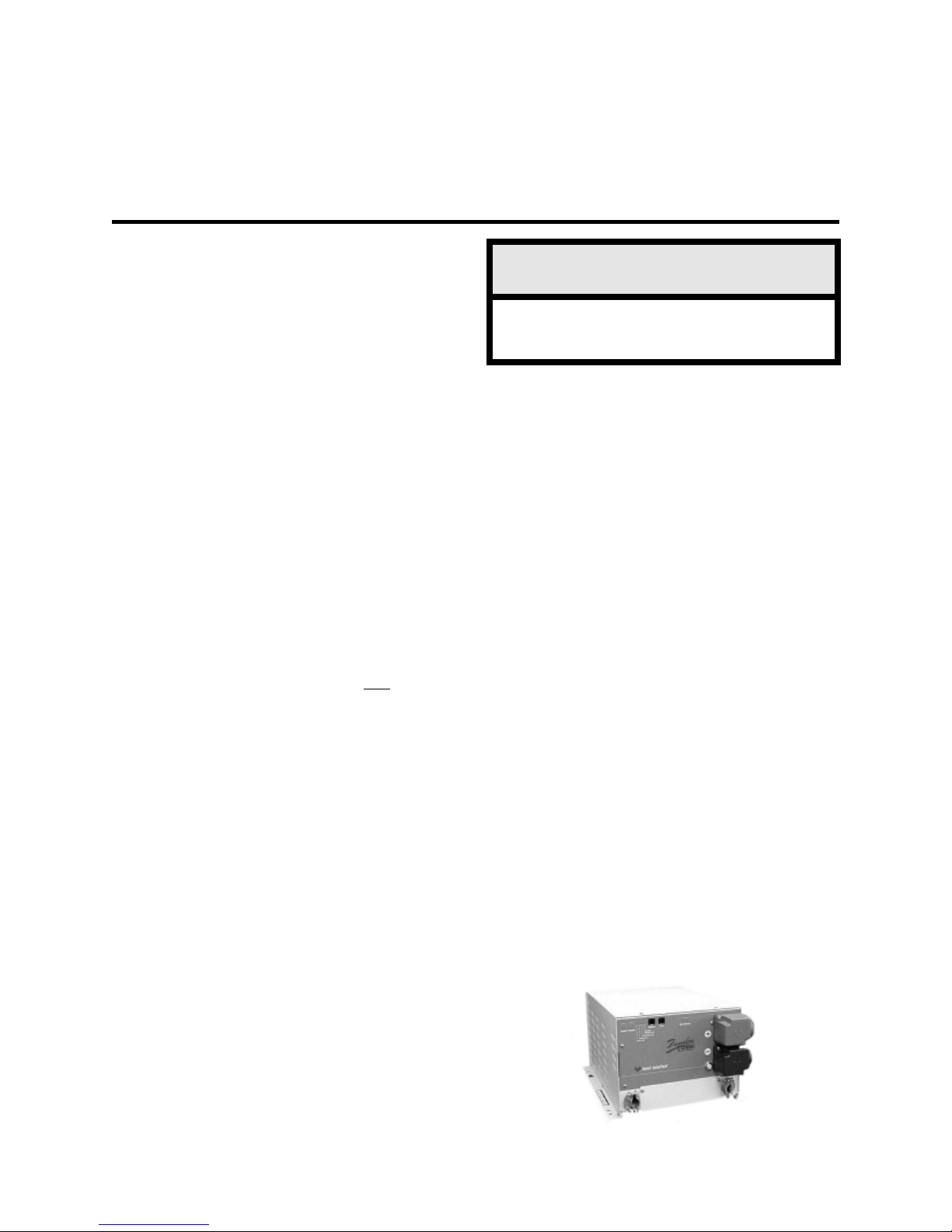
Follow these instructions to insure proper
start up and confirm that the installation is
correct.
INSTINST
INST
INSTINST
WW
ARNINGARNING
W
ARNING
WW
ARNINGARNING
ALLAALLA
ALLA
ALLAALLA
TIONTION
TION
TIONTION
1. 1.
1. Check to make sure Invert and Charge
1. 1.
are OFF. The INVERT LED should not be
illuminated, the CHARGE LED should be
blinking (charger ready but no external AC
power available). If using a Remote Control
Panel or a Link Instrument, make sure inverter
and charger are OFF.
2.2.
2. Check battery polarity. If the unit was
2.2.
connected to the battery with reverse polarity,
the unit will be damaged.
3. 3.
3. Check the battery voltage and ensure
3. 3.
it is within proper range for the unit (10-15.5
VDC).
4. 4.
4. Install the jumper in the Auxiliary
4. 4.
Switch port (AUX SWITCH), if using the inverter without remote. If operating the inverter
with a remote, the jumper should
Do not apply shore power orDo not apply shore power or
Do not apply shore power or
Do not apply shore power orDo not apply shore power or
generator power without preforming thegenerator power without preforming the
generator power without preforming the
generator power without preforming thegenerator power without preforming the
following steps:following steps:
following steps:
following steps:following steps:
1. T1. T
est the inverter function:est the inverter function:
1. T
est the inverter function:
1. T1. T
est the inverter function:est the inverter function:
• •
• With no loads connected to the output of
• •
the inverter, turn the INVERT Switch ON. The
INVERT LED should be blinking green. If using
a remote, turn ON the inverter with the switch
on the Remote Control Panel or Link
Instrument.
• •
• The Freedom unit will produce a slight
• •
buzz. If using a Remote Control Panel or Link
Instrument the INVERT/ CHARGE LEDs will
illuminate and the voltage indicator will display
the battery voltage. The DC Amps LED will not
be lit because the unit is in the idle mode.
notnot
not be used.
notnot
Do not turn the inverter ON before
eliminating any possibility of backfeed.
• •
• Add a load of 7 watts or more to the output
• •
of the inverter. A 40 watt incandescent light
bulb will work fine. The DC Amps LEDs on the
remote will indicate the DC draw from the
battery through the inverter.
••
• Leave the load connected and turn OFF
••
the INVERT mode by pressing the INVERT
switch or turn OFF the INVERT mode from the
Remote Control Panel or Link Instrument.
2. T2. T
est the transfer function:est the transfer function:
2. T
est the transfer function:
2. T2. T
est the transfer function:est the transfer function:
• •
• Be sure the unit is OFF, the INVERT and
• •
CHARGE LEDs are not illuminated. Apply
shore power. I f there is a back-feed in the
installation, the unit will protect itself, the LOW
B ATTERY and OVERTEMP/OVERLOAD LED
will both be blinking rapidly (5 times per
second). Do not proceed until the backfeed
condition has been corrected.
• •
• Once shore power has been applied to the
• •
unit, there will be approximately an 8 second
delay. Then the unit should transfer shore
power and power the load. If this does not
happen, do not proceed. If the LOW BATTERY
and OVERLOAD/OVERTEMP LEDs are blinking rapidly or if you are using a Remote Control
Panel or Link Instrument, check the panel for
back-feed indication. The panel will show an
overload condition. Eliminate the back-feed
condition.
Part No. 90-0123-00
Libertycombi.p65 11/05/99
29
Page 30
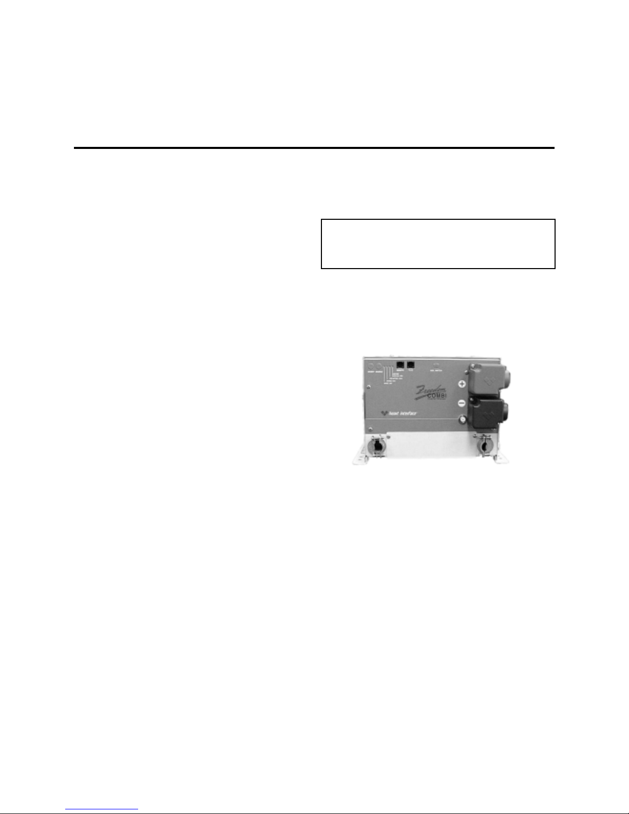
INSTINST
INST
INSTINST
• •
• Testing for backfeed. If a backfeed
• •
condition is indicated, disconnect from shore
power and disconnect the AC output wires on
the inverter. Make sure the inverter is OFF.
Apply shore power and measure for
voltage between the black and white wires that
were attached to the inverter output feeding the
electrical panel or loads, not the inverter output
wires. If there is voltage on these wires, a
back-feed condition exists and must be
corrected or damage will result.
ALLAALLA
ALLA
ALLAALLA
TIONTION
TION
TIONTION
• •
• Turn the INVERT ON, the green LED
• •
should blink. Remove shore power and the
inverter should automatically pick up the AC
load when shore power is removed.
NOTE: For low power system shut down
mode, both the INVERT and CHARGE LEDs
must be OFF.
Repeat the test for transfer and battery
charger with the generator if you have one.
3. T3. T
est the battery charger function:est the battery charger function:
3. T
est the battery charger function:
3. T3. T
est the battery charger function:est the battery charger function:
• •
• With shore power applied and the
• •
transfer switch engaged, the battery charger
should be in operation. The CHARGE LED will
blink for 8 seconds. After the 8 seconds, the
unit will enter the charge mode and the LED
will be illuminated. (NOTE: When using
Temperature Sensitive Charging, this time may
be longer.)
NOTE: When AC is available, the unit will
automatically default to charge mode without
the operator setting the unit in CHARGE mode.
It is necessary to press the CHARGE switch
O F F, if you do not want to charge.
Verify the charger is working by using a
volt meter. The battery voltage should gradually
increase. If using a Remote Control Panel, the
DC Amps LED indicates the current the
charger is putting out and the DC Volts LED
indicates an increase in battery voltage.
Congratulations, you have completed a
successful installation.
30
Part No. 90-0123-00
Libertycombi.p65 11/05/99
Page 31

TROUBLESHOOTING LED STTROUBLESHOOTING LED ST
TROUBLESHOOTING LED ST
TROUBLESHOOTING LED STTROUBLESHOOTING LED ST
sutatSDELsutatSnoitarepOsetoN
TREVNIEGRAHCYRETTABWOLPMETREVO
AA
TUSTUS
A
TUS
AA
TUSTUS
DAOLREVO
neerGdiloSneerGgniknilBFFOFFOontubydaerregrahC.gnitrevnI
.elbaliavaCAlanretxe
gniknilB
neerG
gniknilB
neerG
FFOneerGdiloSFFOFFO.gnigrahC.FFOretrevnIybretrevniehtteseR
neerGdiloSneerGgniknilBdeRdiloS* ontubydaerregrahC.gnitrevnI
neerGdiloSneerGgniknilB* deRdiloSontubydaerregrahC.gnitrevnI
FFOneerGgniknilBgniknilBwolS
FFOneerGgniknilB* gniknilBwolS
neerGdiloSFFOFFO.ybdnatsnisiretrevnI
FFOFFOFFO.ybdnatsinisiretrevnI
*:nwodtuhsegatloVyrettaB
deR
deR
.degrahcgniebsiyrettaB
.ffodenrutyllaunamregrahC
yrettaB.elbaliavaCAlanretxe
:gninraWegatloV
V51>CDV<V01
-revO.elbaliavaCAlanretxe
gninraWerutarepmet
V51>CDV<V01
lanretxeontubydaerregrahC
regrahC.elbaliavarewopCA
nwodtuhSerutarepmet-revo
lamroN
tnerrucgnigrahc,lamroN
sdeecxedaolCAfidetimil
.gnittesgnirahSrewoP
devomersirewopCAfI
regrahceht,deilppaerdna
.NOnrutyllacitamotualliw
.nottubTREVNIgnihsup
.knilbdluohsDEL
egatlovyrettaB.gninraW
nahteromro01nahtssel
stlov51
.nwodtuhsretrevnI.gninraW
.nwodtuhSretrevnI
nehwemuserlliwnoitarepO
stlov5.31sehcaeryrettab
yllacitamotualliwnoitarepO
sahtinuretfaemuser
nwoddelooc
FFOneerGgniknilB* gniknilBtsaF
FFOneerGgniknilBgniknilBtsaF
deR
FFOneerGgniknilBgniknilBtsaF
deR
.sutatsFFOroNOrehtieebdluoC*
Part No. 90-0123-00
Libertycombi.p65 11/05/99
nwodtuhSdaolrevOretrevnIyllaunaM.daolCAecudeR
deR
gniknilBtsaF
deR
FFOelppiRyrettaBgninraW
gniriwCA
tcerrocnI.nwodtuhSdeefkcaB
metsysehttratser
erofebgniriwniCAtcerroC
ehttratseryllaunaM.esu
.metsys
31
Page 32

TROUBLESHOOTINGTROUBLESHOOTING
TROUBLESHOOTING
TROUBLESHOOTINGTROUBLESHOOTING
32
Part No. 90-0123-00
Libertycombi.p65 11/05/99
Page 33

Alternating Current (AC) Alternating Current (AC)
Alternating Current (AC) An electric current
Alternating Current (AC) Alternating Current (AC)
that reverses direction at regular intervals.
Sources of alternating current are shore
power, generator power, inverter power or
household current.
Ampere (Amp, A) Ampere (Amp, A)
Ampere (Amp, A) The unit of measure of
Ampere (Amp, A) Ampere (Amp, A)
electron flow rate of current through a circuit.
Ampere-hour (Amp-HrAmpere-hour (Amp-Hr
Ampere-hour (Amp-Hr
Ampere-hour (Amp-HrAmpere-hour (Amp-Hr
measure for a battery’s electrical storage
capacity, obtained by multiplying the current in
amperes by the time in hours of discharge
(Example: a battery which delivers 5 amperes
for 20 hours delivers 5 amperes times 20
hours, or 100 Amp-Hr. o f capacity. )
Ampere-Hour Capacity Ampere-Hour Capacity
Ampere-Hour Capacity The ability of a fully
Ampere-Hour Capacity Ampere-Hour Capacity
charged battery to deliver a specified quantity
of electricity (Amp-Hr., AH) at a given rate
(Amp, A) over a definite period of time (Hr.).
The capacity of a battery depends upon a
number of factors such as: active material,
weight, density, adhesion to grid, number,
design and dimensions of plates, plate spacing
design of separators, specific gravity and
quantity of available electrolyte, grid alloys, final
limiting voltage, discharge rate, temperature,
internal and external resistance, age and life of
the battery (bank).
., .,
AH) AH)
.,
AH) A unit of
., .,
AH) AH)
GLOSSARGLOSSAR
GLOSSAR
GLOSSARGLOSSAR
first to the positive of the second, negative of
the second to the positive of the third, etc. If
two 6 Volt batteries of 50 ampere-hours
capacity are connected in series, the circuit
voltage is equal to the sum of the two battery
voltages, or 12 Volts, and the ampere-hour
capacity of the combination is 50
ampere-hours.
Circuit (Parallel) Circuit (Parallel)
Circuit (Parallel) A circuit which provides
Circuit (Parallel) Circuit (Parallel)
more than one path for current flow. A parallel
arrangement of batteries (of like voltage and
capacity) would have all positive terminals
connected to a conductor and all negative
terminals connected to another conductor. If
two 12 Volt batteries of 50 ampere-hour
capacity each are connected in parallel, the
circuit voltage is 12 Volts, and the ampere-hour
capacity of the combination is 100
ampere-hours.
Combi Combi
Combi Freedom Combi
Combi Combi
Heart Interface to indicate a combination
inverter/charger.
Current Current
Current The rate of flow of electricity or the
Current Current
movement rate of electrons along a conductor.
It is comparable to the flow of a stream of
water. The unit of measure for current is
ampere.
is a trademark of
TM
YY
Y
YY
AGM (Absorbed Glass Mat) Battery AGM (Absorbed Glass Mat) Battery
AGM (Absorbed Glass Mat) Battery A lead
AGM (Absorbed Glass Mat) Battery AGM (Absorbed Glass Mat) Battery
acid, maintenance-free battery.
AA
WG (American WWG (American W
A
WG (American W
AA
WG (American WWG (American W
used to measure the size of wire.
Circuit Circuit
Circuit An electric circuit is the path of an
Circuit Circuit
electric current. A closed circuit has a
complete path. An open circuit has a broken or
disconnected path.
Circuit (Series) Circuit (Series)
Circuit (Series) A circuit which has only one
Circuit (Series) Circuit (Series)
path for the current to flow. Batteries arranged
in series are connected with the negative of the
Part No. 90-0123-00
Libertycombi.p65 11/05/99
ire Gauge) ire Gauge)
ire Gauge) A standard
ire Gauge) ire Gauge)
Cycle Cycle
Cycle I n a battery, one discharge plus one
Cycle Cycle
recharge equals one cycle.
Direct Current Direct Current
Direct Current (DC) Current that flows
Direct Current Direct Current
continuously in one direction such as that from
batteries, photovoltaics, alternators, chargers
and DC generators.
33
Page 34

GLOSSARGLOSSAR
GLOSSAR
GLOSSARGLOSSAR
YY
Y
YY
Equalize Charge Equalize Charge
Equalize Charge A controlled overcharge of
Equalize Charge Equalize Charge
the batteries which brings all cells up to the
same voltage potential, extends the battery life,
restores capacity and mixes the electrolyte.
This can only be done using the Freedom
Remote Control Panel or a Link Instrument.
Gel Cell Battery Gel Cell Battery
Gel Cell Battery A type of battery that uses a
Gel Cell Battery Gel Cell Battery
gelled electrolyte solution. These batteries are
sealed and are virtually maintenance-free. Not
all sealed batteries are the gel cell type.
GFCI (Ground Fault Circuit Interrupter) GFCI (Ground Fault Circuit Interrupter)
GFCI (Ground Fault Circuit Interrupter) A
GFCI (Ground Fault Circuit Interrupter) GFCI (Ground Fault Circuit Interrupter)
protective device that rapidly de-energizes a
circuit when current to ground exceeds a
predetermined value.
Ground Ground
Ground The reference potential of a circuit. In
Ground Ground
automotive use, the result of attaching one
battery cable to the body or frame which is
used as a path for completing a circuit in lieu of
a direct wire from a component. This method
is not suitable for connecting the negative
cable of the inverter to ground. Instead, route
the cable directly to the negative terminal of the
battery.
LED (Light Emitting Diode) LED (Light Emitting Diode)
LED (Light Emitting Diode) Indicator light.
LED (Light Emitting Diode) LED (Light Emitting Diode)
LINK Instrument LINK Instrument
LINK Instrument These panels monitor single
LINK Instrument LINK Instrument
and dual battery banks. Some models provide
remote management of Freedom Inverter/
Chargers. Available in 4 models: LINK 10,
LINK 20, LINK 1000, LINK 2000, LINK 2000R.
NECNEC
N E C National Electric Code
NECNEC
Negative Negative
Negative Designating or pertaining to
Negative Negative
electrical potential. The negative terminal is the
point from which electrons flow during
discharge.
OhmOhm
O h m A unit for measuring electrical
OhmOhm
resistance.
Ohm’Ohm’
s Laws Law
Ohm’
s Law Expresses the relationship
Ohm’Ohm’
s Laws Law
between Voltage (V) and Current (I) in an
electrical circuit with resistance (R). It can be
expressed as follows: V=IR. If any two of the
three values are known, the third value can be
calculated by using the above formula.
Positive Positive
Positive Designating or pertaining to electrical
Positive Positive
potential; opposite of negative. The positive
battery terminal is the point where electrons
return to the battery during discharge.
Power Sharing Power Sharing
Power Sharing The feature of the charger to
Power Sharing Power Sharing
reduce its output when the AC power being
consumed by the charger and external AC
loads connected to the output of the inverter
are in excess of the input breaker rating.
TSC TSC
TSC Abbreviation for Temperature Sensitive
TSC TSC
Charging. The ability of the charger to adjust its
charging voltage based on the temperature
sensed at the battery bank if a temperature
probe is used.
VV
olt olt
V
olt The unit of measure for electric potential.
VV
olt olt
WW
att att
W
att The unit for measuring electrical power,
WW
att att
i.e., the rate of doing work, in moving electrons
by or against an electric potential.
WW
att-Hour (Watt-Hour (W
W
att-Hour (W
WW
att-Hour (Watt-Hour (W
measuring electrical energy which equals
W atts x Hours.
Wet Cell Battery Wet Cell Battery
Wet Cell Battery A type of battery
Wet Cell Battery Wet Cell Battery
liquid as an electrolyte. The wet cell battery
requires periodic maintenance; cleaning the
connections, checking the electrolyte level and
performing an equalization cycle.
att-HR, WH)att-HR, WH)
att-HR, WH) The unit for
att-HR, WH)att-HR, WH)
that uses
34
Part No. 90-0123-00
Libertycombi.p65 11/05/99
Page 35

SPECIFICASPECIFICA
SPECIFICA
SPECIFICASPECIFICA
TIONSTIONS
TIONS
TIONSTIONS
ledoM)seireS854(01854(*D51dna51
rebmuNtraP21-0101-18dna21-0151-18
lanimoN
yrettaB
egatloV
yrettaB
egatloV
egnaR
yrettaBwoL
tuotuC
tupnICA
egatloV
egnaR
ycneuqerF
noitalugeR
retrevnI
tuptuO
rewoP
)suounitnoC(
retrevnI
egatloV
noitalugeR
epahSevaWeniSdeifidoM
rewoPegruSspmA03spmA55spmA07spmA08spmA09
daoLoN
tnerruC
niarD
)edoMeldI(
rewoP
srotcaF
dewollA
daoLlluF
ycneiciffE
kaeP
ycneiciffE
noitcetorPytilitUrednU/revO
gnigrahC
etaR
tupnICA
.xaM(
egrahC
)edoM
egrahCkluB
egatloV
egrahCtaolF
egatloV
gnizilauqE
egrahC
egatloV
lenaPsutatSetomeRlanoitpO
thgieW.sbl53.sbl54.sbl54sbl05.sbl05
snoisnemiDxW"5.11xL"2.31
CDV21CDV21CDV21CDV21CDV21
CDV5.51-01CDV5.51-0.01
CDV5.0-/+01)5.0-/+(CDV0.01)5.0-/+(CDV0.01)5.0-/+(CDV0.01)5.0-/+(CDV0.01
CAV09muminiM
CAV031lamroN
zH06ro05
detalugeRztrauQ
AV0001AV0051AV0002AV0052AV0003
SMR
evaW
llAllAllAllAllA
%39%29%39%39%39
revO
)egats
**3.41**CDV3.41**CDV3.41**CDV3.41**CDV3.41
kniLro
H"9.7
tuptuOCAlauD*
.lenaPlortnoCetomeR
eurT%5-/+V021
spmA21.pmA21.pmA21.spmA21.spmA21.
)zH06(%58)zH06(%68)zH06(%58%78)zH06(%68)zH06(
,egataloV
rednU/revO
,egatloVyrettaB
,tiucriC-trohS
,rekaerBtiucriC
,erutarepmeT
deefkcaB
-3(spmA05
spmA21spmA71spmA12spmA62spmA82
**CDV4.31**CDV4.31**CDV4.31**CDV4.31CDV4.31**
CDV3.61**CDV3.61**CDV3.61**CDV3.61**CDV3.61
)seireS
21-0251-18
)2.0-/+(
CAV09muminiM
CAV031lamroN
zH06ro05
detalugeRztrauQ
SMR
evaW
,egatloV
revO
)egats
kniLro
H"9.7
eurT%5-/+V021
eniSdeifidoM
ytilitUrednU/revO
rednU/revO
,egatloVyrettaB
,tiucriC-trohS
,rekaerBtiucriC
,erutarepmeT
deefkcaB
-3(spmA57
etomeRlanoitpO
stnemurtsnI
xW"5.11xL"2.31
)seireS
)2.0-/+(
SMR
evaW
,egatloV
revO
deefkcaB
)egats
kniLro
H"9.7
854(*D02dna02
dna21-0102-18
21-0202-18
CDV5.51-0.01
CAV09muminiM
CAV031lamroN
zH06ro05
detalugeRztrauQ
eurT%5-/+V021
eniSdeifidoM
ytilitUrednU/revO
rednU/revO
,egatloVyrettaB
,tiucriC-trohS
,rekaerBtiucriC
,erutarepmeT
-3(spmA001
etomeRlanoitpO
stnemurtsnI
xW"5.11xL"2.31
ybelbatsujdadnadellatsnirosneSerutarepmeThtiwtinunoelbairaV**
ehtmorfrolenaplortnocregrahc/retrevniehtnodetcelesepyTyrettaB
SMR
evaW
)egats
kniLro
H"9.7
21-0152-1821-0103-18
)2.0-/+(
zH06ro05
eniSdeifoM
,egatloV
rednU/revO
tiucriC-trohS
erutarepmeT
deefkcaB
stnemurtsnI
revO,rekaerB
-3(spmA031
seireS854(52)seireS854(03
CDV5.51-0.01
CAV09muminiM
CAV031lamroN
detalugeRztrauQ
eurT%5-/+V021
ytilitUrednU/revO
,egatloVyrettaB
etomeRlanoitpO
xW"5.11xL"2.31
CDV5.51-0.01
CAV09muminiM
CAV031lamroN
zH06ro05
detalugeRztrauQ
SMR
evaW
,egatloV
revO
)egats
kniLro
H"9.7
eurT%5-/+V021
eniSdeifidoM
ytilitUrednU/revO
rednU/revO
,egatloVyrettaB
,tiucriC-trohS
,rekaerBtiucriC
,erutarepmeT
deefkcaB
-3(spmA041
etomeRlanoitpO
stnemurtsnI
xW"5.11xL"2.31
Part No. 90-0123-00
Libertycombi.p65 11/05/99
35
Page 36

WW
ARRANTYARRANTY
W
ARRANTY
WW
ARRANTYARRANTY
Your Heart Interface Freedom 458 Series
CombiTM Inverter/Charger is under limited
warranty for 30 months from date of purchase.
TT
erms of this warranty are detailed onerms of this warranty are detailed on
T
erms of this warranty are detailed on
TT
erms of this warranty are detailed onerms of this warranty are detailed on
the warranty registration card. Pleasethe warranty registration card. Please
the warranty registration card. Please
the warranty registration card. Pleasethe warranty registration card. Please
complete this card and return it to Heartcomplete this card and return it to Heart
complete this card and return it to Heart
complete this card and return it to Heartcomplete this card and return it to Heart
Interface to register your warrantyInterface to register your warranty
Interface to register your warranty
Interface to register your warrantyInterface to register your warranty
If the unit requires service, contact Heart
Interface by telephone. The service technician
will ask for the model and serial number of your
unit. Please have this information ready.
..
.
..
Phone numbers:Phone numbers:
Phone numbers:
Phone numbers:Phone numbers:
A return authorization number will be
required on all returns. This number is issued
by the service technician and should be written
on the outside of the packaging
You must ship the unit to Heart Interface
or a field service center freight prepaid.
(253) 872-7225(253) 872-7225
(253) 872-7225
(253) 872-7225(253) 872-7225
(800) 446-6180(800) 446-6180
(800) 446-6180 (outside 253 area code)
(800) 446-6180(800) 446-6180
Inverter/Chargers
© 1998 Heart Interface Corporation. All rights reserved.
36
Part No. 90-0123-00
Libertycombi.p65 11/05/99
UL
 Loading...