

Page 1
FUTURE REFERENCE
Vent
–
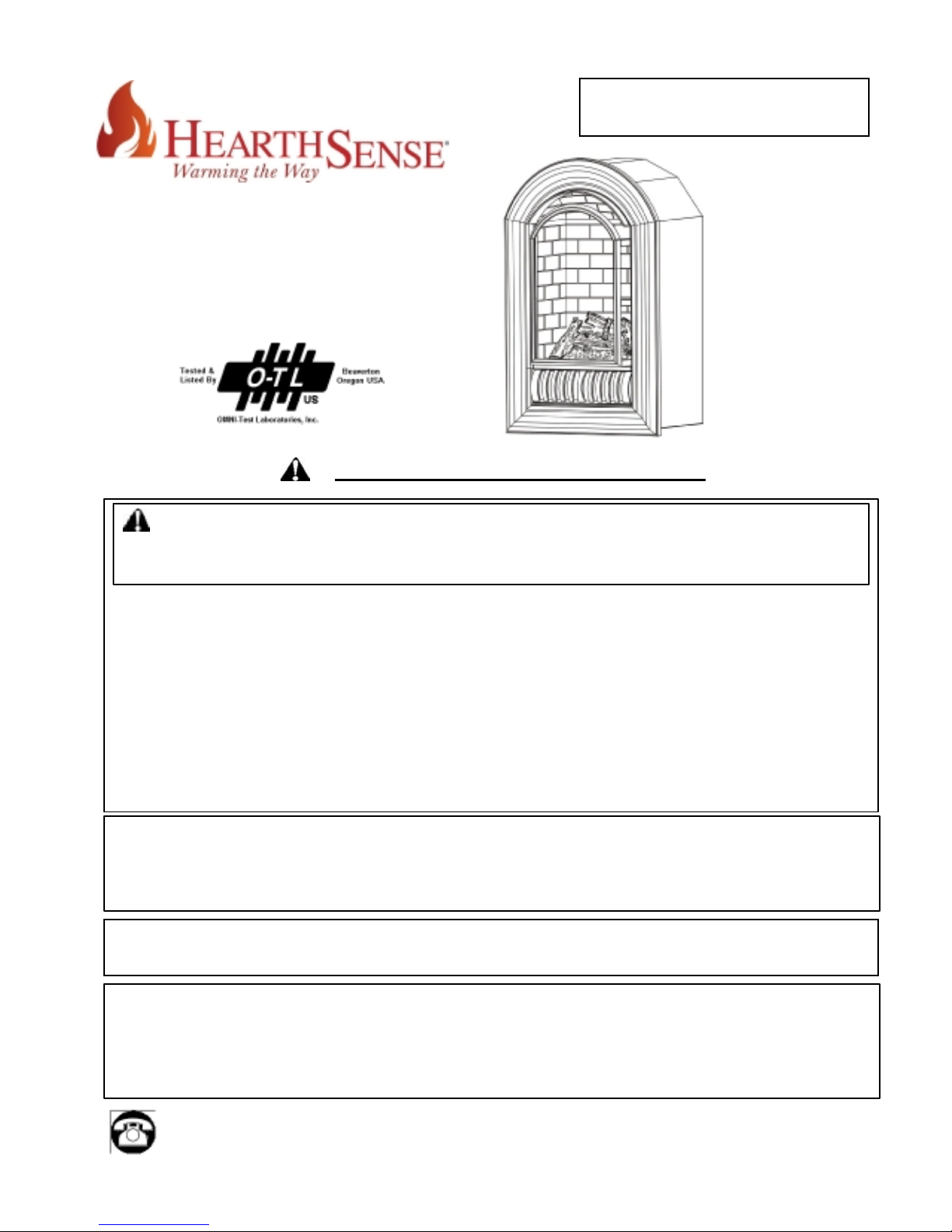
Free Arched Fireplace
Model: ANI & ALI
CAUTION – FOR YOUR SAFETY
WARNING: IF THE INFORMATION IN THIS MANUAL IS NOT FOLLOWED
EXACTLY, A FIRE MAY RESULT CAUSING PROPERTY DAMAGE, PERSONAL
INJURY OR LOSS OF LIFE.
-- Do not store or use gasoline or other flammable vapors and liquids in vicinity
of this or any other appliance.
WHAT TO DO IF YOU SMELL GAS
l Do not try to light any appliance.
l Do not touch any electrical switch; do not use any phone in your building.
l Immediately call your gas supplier from a neighbor’s phone. Follow
the gas supplier’s instructions.
l If you cannot reach your gas supplier, call the fire department.
-- Installation and service must be performed by a qualified installer, service
agency or the gas supplier.
This is an unvented gas-fired heater. It uses air (oxygen) from the room in which it
is installed. Provisions for adequate combustion and ventilation air must be
provided.
Refer to Air For Combustion and Ventilation section on page 6 of this manual.
INSTALLER: DO NOT DISCARD THIS MANUAL – LEAVE WITH HOMEOWNERS FOR
This appliance may be installed in an aftermarket, permanently located,
manufactured (mobile) home, where not prohibited by local codes.
This appliance is only for use with the type of gas indicated on the rating plate.
This appliance is not convertible for use with other gases.
Questions about installation, operation, or troubleshooting? Before returning to your retailer, call our
customer service department toll-free at 1-877-886-5989
HS-AN/LI 200MV– 509-0708
Page 2
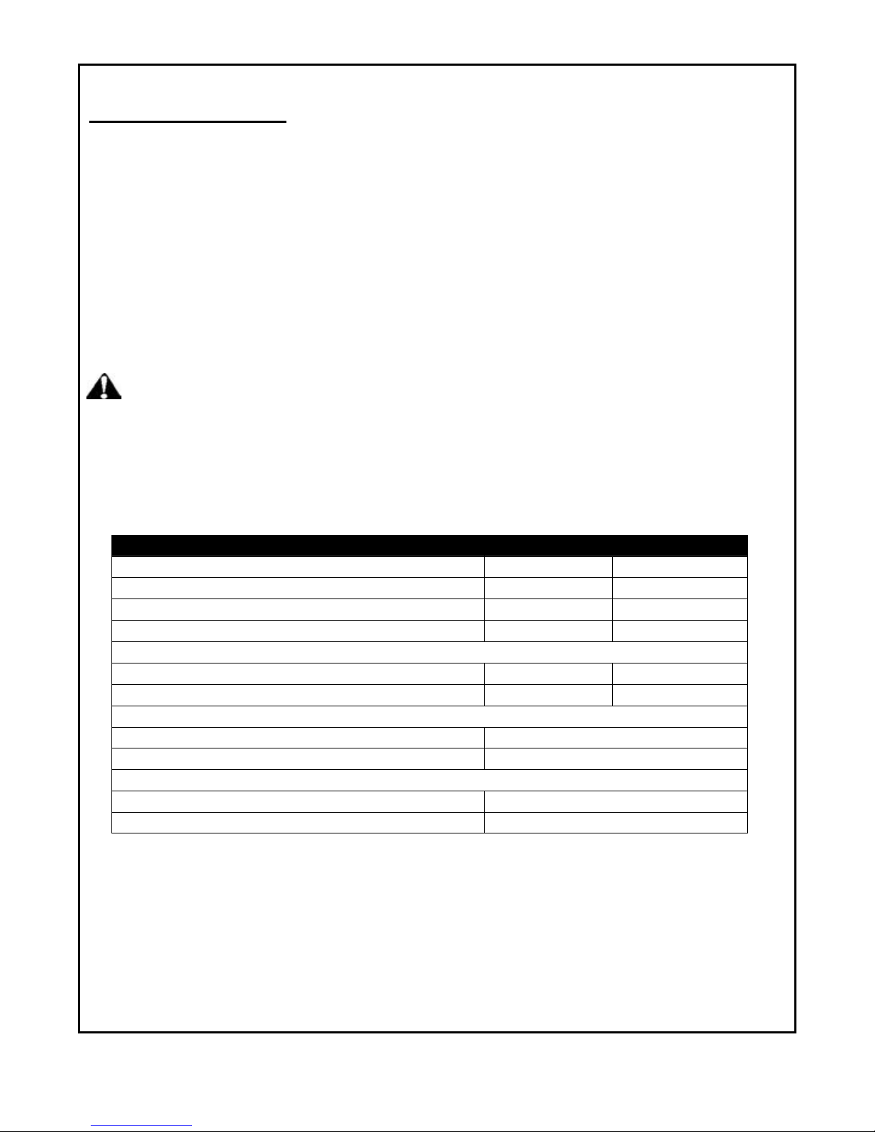
TABLE OF CONTENTS
Important Safety Information.............................................................................................................................................3
Air for Combustion and Ventilation..................................................................................................................................6
Installation ...........................................................................................................................................................................8
Operating............................................................................................................................................................................17
Cleaning & Maintenance ..................................................................................................................................................20
Troubleshooting ................................................................................................................................................................21
Replacement Parts………………………………………………………………………………………………………………23
WARNING: READ THE INSTALLATION & OPERATION INSTRUCTIONS
BEFORE USING THIS APPLIANCE
IMPORTANT: Read instructions and warnings carefully before starting installation. Failure to follow
these instructions may result in a possible fire hazard and will void the warranty.
PRODUCT SPECIFICATIONS
ITEM NO. ANI ALI
Input Rating 20,000 BTU/Hr 20,000 BTU/Hr
Gas Type Natural LP/Propane
Ignition Piezo /Automatic Piezo /Automatic
Manifold Pressure 3.5”W.C. 10”W.C.
Inlet Gas Pressure
Maximum 10.5” 14”
Minimum 5” 11 ”
Dimensions, inches(HxWxD)
Heater 34 1/2” x 21 1/2” x 15”
Carton 38” x 24” x 17 1/10”
Weight, lbs
Stove 77.2
Shipping 94
*For purposes of input adjustment
2
Page 3
ith
IMPORTANT SAFETY INFORMATION
IMPORTANT:
Read this owner’s manual carefully and completely before trying to assemble, operate, or service this
heater. Improper use of this heater can cause serious injury or death from burns, fire, explosion, electrical
shock, and carbon monoxide poisoning.
Installation and service must be performed by a qualified installer, service agency, or local gas
supplier.
WARNING: Do not store or use gasoline or other flammable vapors or liquids in the vicinity of this
or any other appliance.
CARBON MONOXIDE POISONING: Early signs of carbon monoxide poisoning resemble the flu with
headaches, dizziness, or nausea. If you have these signs, the heater may not be working properly.
Get fresh air immediately! Have heater serviced. Some people are more affected by carbon monoxide
than others. These include pregnant women, people with heart, or lung disease, anemia, those under
the influence of alcohol, and those at high altitudes.
NATURAL AND PROPANE/LP GAS: Natural and Propane/LP gases are odorless. An odor-making
agent is added to the gas. The odor helps you detect a gas leak. However, the odor added to the gas
can fade. Gas may be present even though no odor exists. Make certain you read and understand all
warnings. Keep this manual for reference. It is your guide to safe and proper operation of this heater.
WARNING: Any change to this fireplace or its controls can be dangerous.
WARNING: Do not allow fans to blow directly into the heater. Avoid any drafts that alter burner
flame patterns including ceiling fans. Altered burner patterns can cause sooting.
Do not use a blower insert, heat exchanger insert, or other accessory not approved for use w
this heater.
Due to high temperatures, the appliance should be located out of traffic and away from furniture
and draperies.
Do not place clothing or other flammable material on or near the appliance. Never place any objects
in the fireplace. Heater becomes very hot when running fireplace. Keep children and adults away
from hot surfaces to avoid burns or clothing ignition. Fireplace will remain hot for a time after
shutdown. Allow surfaces to cool before touching. Carefully supervise young children when they
are in the room with fireplace.
You must operate this heater with the heater glass screen in place.
Keep the appliance area clear and free from combustible materials, gasoline, and other flammable
vapors and liquids.
3
Page 4

IMPORTANT SAFETY INFORMATION (CONTINUED)
This appliance is for use with only the type of gas indicated on the rating plate. This appliance is not
convertible for use with other gases.
1. Do not place Propane/LP supply tank(s) inside any structure. Store Propane/LP supply tank(s) outdoors.
2. This heater shall not be installed in a bedroom or bathroom.
3. Do not use this heater as a wood-burning heater. Use only the logs provided with the heater.
4. Do not add extra logs or ornaments such as pine cones, vermiculite, or rock wool. Using these added items can
cause sooting. Do not add lava rock around base. Rock and debris could fall into the control area of heater. After
servicing, always replace glass screen before operating heater.
5. Make sure the heater glass screen is in place before running the heater.
6. This heater is designed to be smokeless. If logs ever appear to smoke, turn off heater and call a qualified
service person. Note: During initial operation, slight smoking could occur due to log curing and the heater
burning manufacturing residues.
7. To prevent the creation of soot, follow the instructions in Cleaning and Maintenance (page 19).
8. Before using furniture polish, wax, carpet cleaner, or similar products, turn heater off. If heated,
the vapors from these products may create a white powder residue within burner box or on
adjacent walls or furniture.
9. This heater needs fresh air ventilation to run properly. This heater has an Oxygen Depletion
Sensing (ODS) safety shutoff system. The ODS shuts down the heater if not enough fresh air
is available. See Air for Combustion and Ventilation, pages 6 through 8. If heater keeps
shutting off, see Troubleshooting, pages 21 through 23.
10. Do not run heater:
Where flammable liquids or vapors are used or stored.
Under dusty conditions.
11. Do not use this heater to cook food or burn paper or other objects.
12. Do not use this heater if any part has been under water. Immediately call a qualified service
technician to inspect the room heater .
13. Turnoff and unplug heater and let cool before servicing. Only a qualified service person should
service and repair heater.
14. Operating heater above elevations of 4,500 feet could cause pilot outage.
15. Do not operate heater if any log is broken. Do not operate heater if any log is chipped (dime-sized or larger).
16. To prevent performance problems, do not use a propane/LP fuel tank of less than 100 lbs capacity.
4
Page 5
QUALIFIED INSTALLING AGENCY
Installation and replacement of gas piping, gas utilization equipment or accessories and repair and
servicing of equipment should be performed only by a qualified agency. The term “qualified agency”
means any individual, firm, corporation, or company that either in person or through a representative is
engaged in and is responsible for:
a) The installation, testing, or replacements of gas piping or
b) The connection, installation, testing, repair, or servicing of equipment; that is experienced in such
work; that is familiar with all precautions required; and that has complied with all the requirements of
the authority having jurisdiction.
PRODUCT FEATURES
Safety Pilot
This heater has a pilot with an Oxygen Depletion Sensing (ODS) safety shutoff system. The ODS/pilot is
a required feature for vent-free room heaters. The ODS/pilot shuts off the heater if there is not enough
fresh air.
Piezo Ignitor System
This heater is equipped with an electronic piezo ignitor. This system requires AAA batteries (provided).
Millivolt Gas Control
Allowes heater to operate by a wall thermostat or remote control (sold separately) .
LOCAL CODES
Install and use heater with care. Follow all local codes. In the absence of local
Codes use the latest edition of the national fuel gas code, ANSIZ 223.1, also known as NFPA54*.
*Available from:
American National Standards Institute, lnc.
1430 Broadway
New York, NY 10018
National Fire Protection Association, lnc.
1Batterymarch Park
Quincy, MA 02269-9101
This heater is designed for vent-free operation. State and local codes in some areas prohibit the use of
vent-free heaters.
State of Massachusetts: The installation must be made by a licensed plumber or gas fitter in the
Commonwealth of Massachusetts. Sellers of unvented propane or natural gas-fired supplemental room
heaters shall provide to each purchaser a copy of 527 CMR 30 upon sale of the unit.
In the State of Massachusetts, unvented propane or natural gas-fired space heaters shall be prohibited
in bedrooms and bathrooms.
In the State of Massachusetts the gas cock must be a T-handle type. The State of Massachusetts
requires that a flexible appliance connector cannot exceed three feet in length.
5
Page 6
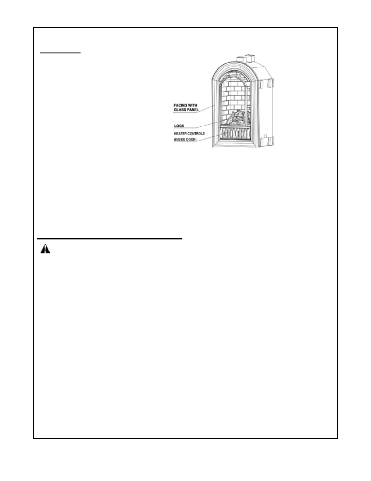
Figure 1
UNPACKING
1. Remove top inner pack
2. Tilt carton so that fireplace is upright.
3. Remove protective side packaging.
4. Slide fireplace out of carton.
5. Remove protective plastic wrap.
6. Hold the panel lift and pull forward.
7. Remove log set by cutting plastic ties.
8. Carefully un-wrap log.
9. Check for any shipping damage. If fireplace
or log is damaged, promptly inform your
dealer where you bought the fireplace.
PRODUCT IDENTIFICATION
WATER VAPOR: A BY-PRODUCT OF UNVENTED ROOM HEATERS
Water vapor is a by-product of gas combustion. An unvented room heater produces approximately one (1)
ounce (30ml) of water for every 1,000 BTUs (.3KWs) of gas input per hour.
An unvented room heater is recommended as a supplemental heater (one room) rather than a primary heat
source (an entire house). In most supplemental heat applications, the water vapor does not create a
problem. In most applications, the water vapor enhances the low humidity atmosphere experienced during
cold weather. The following steps will help ensure that water vapor does not become a problem.
1. Be sure the heater is sized properly for the application, including adequate combustion air and circulation air.
2. If high humidity is experienced, a dehumidifier may be used to help lower the water vapor content of the air.
3. Do not use an unvented room heater as the primary heat source.
AIR FOR COMBUSTION AND VENTILATION
WARNING: This heater shall not be installed in a confined space or unusually tight construction
unless provisions are provided for adequate combustion and ventilation air. Read the following
instructions to insure proper fresh air for this and other fuel-burning appliances in your home:
Producing Adequate Ventilation
The following are excerpts from National Fuel Gas Code, NFPA 54/ANSI Z 223.1, Section 5.3, Air for
Combustion and Ventilation.
All spaces in homes fall into one of the three following ventilation classifications:
1. Unusually Tight Construction
2. Unconfined Space
3. Confined Space
The information on pages 6 through 8 will help you classify your space and provide adequate ventilation.
Confined and Unconfined Space
The National Fuel Gas Code, ANS Z223.1 defines a confined space as a space whose volume is less than
50 cubic feet per 1,000 Btu per hour (4.8 m3 per kw) of the aggregate input rating of all appliances installed
in that space and an unconfining space as a space whose volume is not less than 50 cubic feet per 1,000
Btu per hour (4.8 m3 per kw) of the aggregate input rating of all appliances installed in that space. Rooms
connected directly with the space in which the appliances are installed*, through openings not furnished with
doors, are considered a part of the unconfined space.
This heater shall not be installed in a confined space or unusually tight construction unless provisions are
provided for adequate combustion and ventilation.
* Adjoining rooms are connecting only if there are doorless passageways or ventilation grills between them.
Unusually Tight Construction
The air that leaks around doors and windows may provide enough fresh air for combustion and ventilation.
However, in buildings of unusually tight construction, you must provide additional fresh air.
6
Page 7
Unusually tight construction is defined as construction where:
a) walls and ceilings exposed to the outside atmosphere have a continuous water vapor retarder with a rating of one
perm (6x10-11kg per pa-sec-m2) or less with openings gasketed or sealed and
b) weather stripping has been added on windows that can be opened and doors and
c) caulking or sealants are applied to areas such as joints around window and door frames, between sole plates
and floors, between wall-ceiling joints, between wall panels, at penetrations for plumbing, electrical, and gas
lines, and at other openings.
If your home meets all of the three criteria above, you must provide additional fresh air. See Ventilation Air From
Outdoors (page 8). If your home does not meet all of the three criteria above, proceed to "Determining Fresh-Air Flow
For Heater Location" (below).
DETERMINING FRESH-AIR FLOW FOR HEATER LOCATION
Determining if You Have a Confined or Unconfined Space
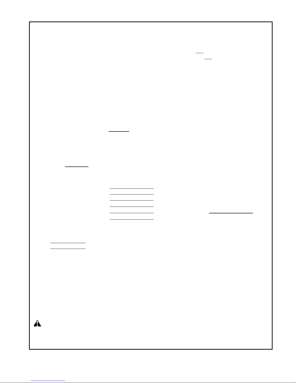
Use this worksheet to determine if you have a confined or unconfined space.
Space: Includes the room in which you will install heater plus any adjoining rooms with doorless passageways or
ventilation grills between the rooms.
1. Determine the volume of the space
Length×Width×Height= cu.ft. (volume of space)
Example: Space size 20ft. (length) × 16ft. (width) × 8ft. (ceiling height) = 2560cu. ft. (volume of space) If additional
ventilation to adjoining room is supplied with grills or openings, add the volume of these rooms to the total volume of
the space.
2. Divide the space volume by 50 cubic feet to determine the maximum Btu/Hr the space can support.
(volume of space) ÷ 50 cu. ft. = (Maximum Btu/Hr the space can support)
Example: 2560 cu. ft. (volume of space)?0 cu.ft.=51.2 or 51,200(maximum Btu/Hr the space can support)
3. Add the Btu/Hr of all fuel burning appliances in the space.
Vent-free heater
Gas water heater*
Gas furnace
Vented gas heater
Gas heater logs
Other gas appliances* +
Total =
*Do not include direct-vent gas appliances. Direct-vent draws combustion air from the outdoors and vents to the outdoors.
Btu/Hr
Btu/Hr
Btu/Hr Example:
Btu/Hr Gas water heater 30,000 Btu/Hr
Btu/Hr Vent-free heater + 26,000 Btu/Hr
Btu/Hr Total = 56,000 Btu/Hr
4. Compare the maximum Btu/Hr the space can support with the actual amount of Btu/Hr used.
Btu/Hr (maximum the space can support)
Btu/Hr (actual amount of Btu/Hr used)
Example: 51,200 Btu/Hr (maximum the space can support)
56,000 Btu/Hr (actual amount of Btu/Hr used)
The space in the above example is a confined space because the actual Btu/Hr used is more than the
maximum Btu/Hr the space can support. You must provide additional fresh air. Your options are as follows:
a) Rework worksheet, adding the space of an adjoining room. If the extra space provides an unconfined
space, remove door to adjoining room or add ventilation grills between rooms. See “Ventilation Air from
Outdoors,” page 8.
b) Vent room directly to the outdoors. See “Ventilation Air from Outdoors,” page 8.
c) Install a lower Btu/Hr heater, if lower Btu/Hr size makes room unconfined. If the actual Btu/Hr used is
less than the maximum Btu/Hr the space can support, the space is an unconfined space. You will need no
additional fresh air ventilation.
WARNING: If the area in which the heater may be operated is smaller than that defined as an unconfined
Space or if the building is of unusually tight construction, provide adequate combustion and ventilation air by
one of the methods described in the National Fuel Gas Code, ANSI Z223.1, Section 5.3 or applicable local
codes.
7
Page 8
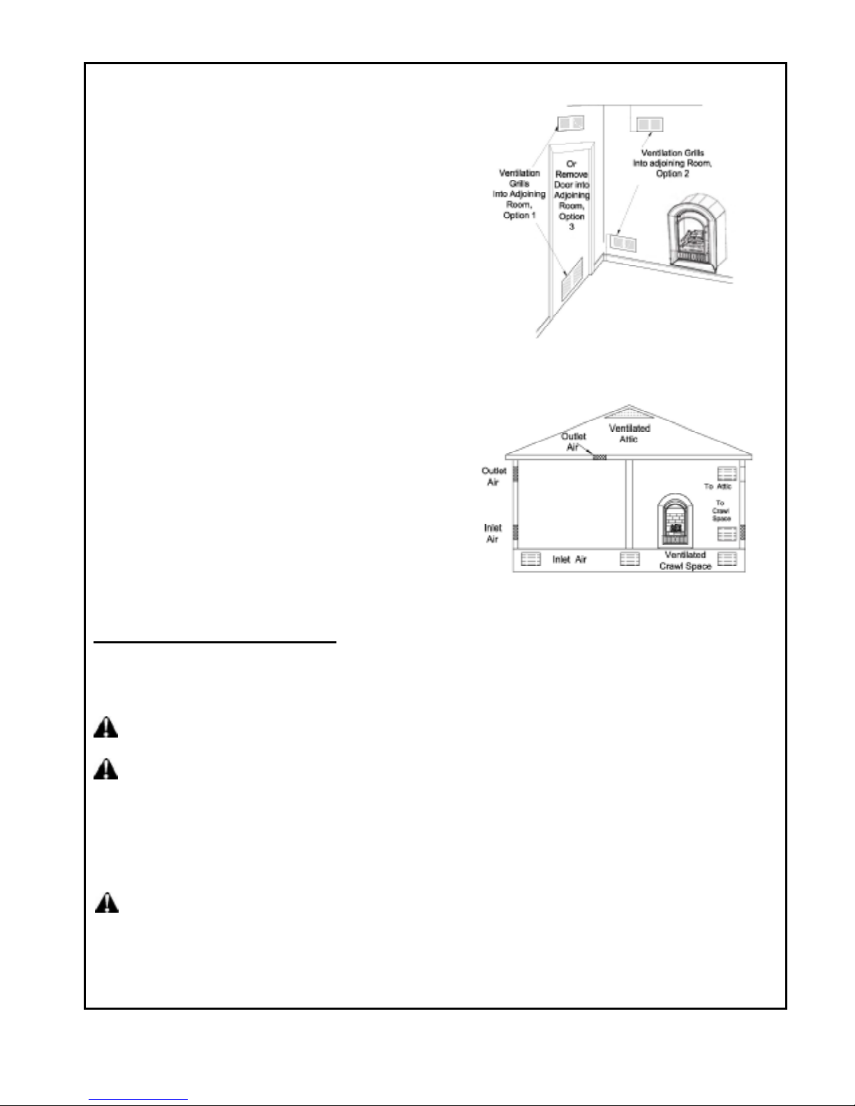
Ventilation Air From Inside Building
This fresh air would come from adjoining unconfined space.
When ventilating to an adjoining unconfined space, you
must provide two permanent openings: one within 12 inches
of the wall connecting the two spaces (see options 1 and 2,
Figure 2). You can also remove door into adjoining room
(see option 3, Figure 2). Follow the National Fuel Gas Code
NFPA 54/ANS Z223.1. Section 5.3, Air for Combustion and
Ventilation for required size of ventilation grills or ducts.
Ventilation Air From Outdoors
Provide extra fresh air by using ventilation grills or duct. You
must provide two permanent openings: one within 12 inches
of the ceiling and one within 12 inches of the floor. Connect
these items directly to the outdoors or spaces open to the
outdoors. These spaces include attics and crawl spaces.
Follow the National Fuel Gas Code NFPA 54/ANS Z223.1,
Section 5.3. Air for Combustion and Ventilation for required
size of ventilation grills or ducts.
IMPORTANT: Do not provide openings for inlet or outlet air
into attic if attic has a thermostat-controlled power vent.
Heated air entering the attic will activate the power vent.
Rework worksheet, adding the space of the adjoining
unconfined space. The combined spaces must have
enough fresh air to supply all appliances in both spaces.
INSTALLATION
NOTICE: This heater is intended for use as supplemental heat. Use this heater along with your primary heating
system. Do not install this heater as your primary heat source. If you have a central heating system, you may run
your system's circulating blower while using heater. This will help circulate the heat throughout the house.
Figure 2 -Ventilation Air from Inside Building
Figure3 -Ventilation Air from Outdoors
WARNING: A qualified technician person must install heater. Follow all local codes.
WARNING: Never install the heater
· In a bedroom or bathroom
· In a recreational vehicle
· Where curtains, furniture, clothing, or other flammable objects are less than 42 inches from the
front, top or sides of the heater.
· In high traffic areas
· In wind or drafty areas
WARNING: Maintain the minimum clearances. If you can, provide greater clearances from floor, ceiling, and
adjoining side and back walls.
CAUTION: This heater creates warm air currents. These currents move heat to wall surfaces next to heater.
Installing heater next to vinyl or cloth wall coverings or operating heater where impurities (such as tobacco smoke,
aromatic candles, cleaning fluids, oil or kerosene lamps, etc.) in the air exist may discolor walls.
8
Page 9
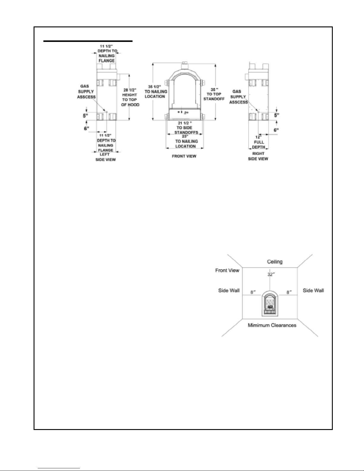
Figure
4 – Fireplace Dimensions
Figure
5 –
Minimum Clearance To
INSTALLATION Continued
IMPORTANT: Vent-free heaters add moisture to the air. Although this is beneficial, installing heater in rooms without
enough ventilation air may cause mildew to form from too much moisture. See Air for Combustion and Ventilation,
pages 6 through 8.
CHECK GAS TYPE
Use only the type of gas indicated on the plate. If your gas supply can not meet that requirement, do not install heater.
CLEARANCES TO COMBUSTIBLES
Carefully follow the instructions below.
IMPORTANT: You must maintain minimum wall and ceiling clearances during installation. The minimum clearances
are shown in Figure 5. Measure from outermost point of fireplace.
Minimum Wall and Ceiling Clearances (see Figure 5)
A. Clearances from outermost point of fireplace to any combustible
B. side wall should not be less than 8 inches.
C. Clearances from the fireplace to the ceiling should not be less
than 32 inches.
NOTE: Surface temperatures of adjacent walls and mantels become
hot during operation. Walls and mantels above the firebox may
become hot to the touch. If installed properly, these temperatures
meet the requirement of the national product standard. Follow all
minimum clearances shown in this manual. See Figure 5 and 11
on page 11.
INSTALLATION INTO PRE-FABRICATED MANTELS
The fireplace can be positioned into HearthSense cabinet mantels.
Follow the installation instructions for mounting
fireplace into mantel.
IMPORTANT: Only use HearthSense pre-fabricated cabinet mantels.
.
Wall And Ceiling
9
Page 10
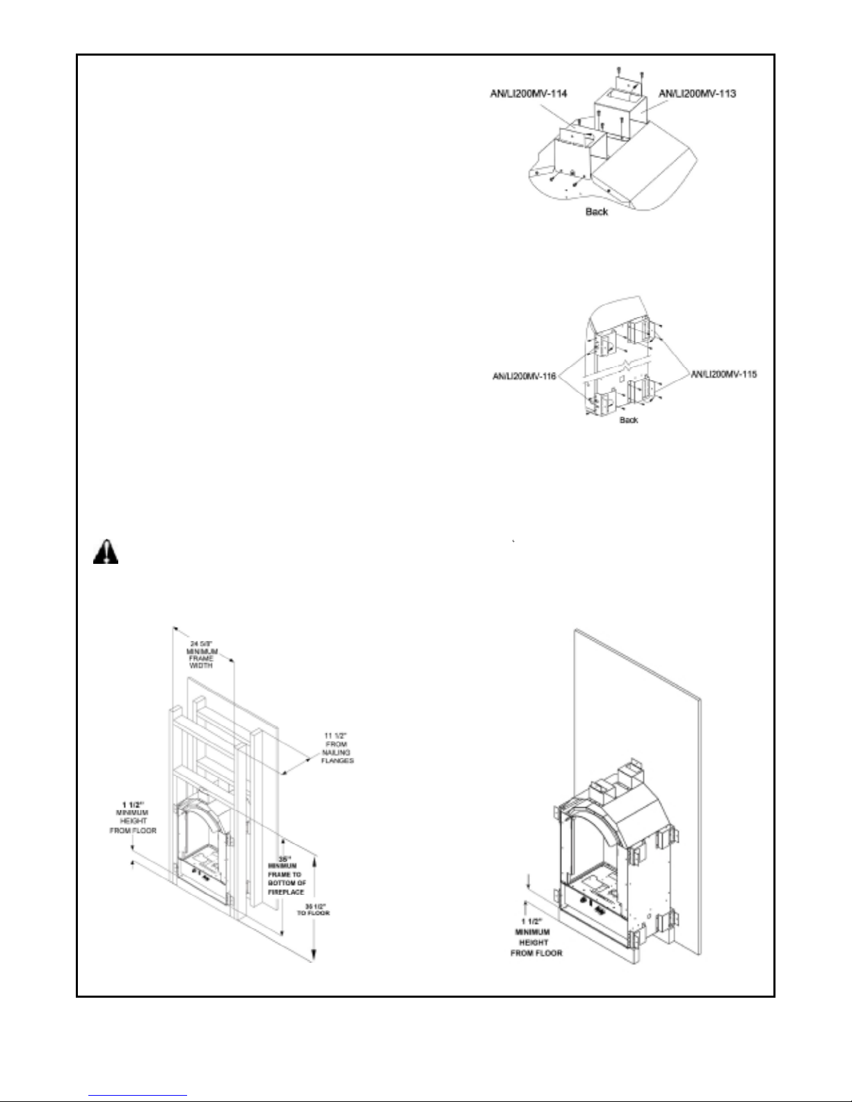
Figure
6 –
Nailing Flanges
NOTE:
Before in
stalling the fireplace into a
and bend outward 90 degrees.
BUILT-IN FIREPLACE INSTALLATION
Built-in installation of this fireplace involves installing
fireplace into a framed-in enclosure. This makes the
front of the fireplace flush with wall.
IMPORTANT: Framing dimensions should allow for wall
covering thickness and fireplace facing materials. Adjust
rough opening size as necessary to maintain at least the
minimum clearance requirements.
1. Frame in rough opening. Use dimensions shown in
Figure 7 and 8 for the rough opening. If installing in a
corner, use dimensions shown in Figure 9 for the rough
opening.
2. Carefully set fireplace in rough opening. Once in place
nail or screw the nailing brackets to the framing.
See Figure 6 for nailing flanges position.
3. Attach gas line to fireplace. See "Connecting to Gas Supply," page 12.
4. Check all gas connections for leaks. See Checking Gas Connections, page 13.
IMPORTANT: When finishing your firebox, combustible materials such as wall board, gypsum board, sheet rock,
drywall, plywood, etc, must have 1” clearance to the sides and 3” to top of the firebox. The framing material may
touch the nailing flange stand-offs, but no material should be placed between the nailing flange stand-offs.
Combustible materials should never overlap the firebox front facing.
recessed space, installer must
attach brackets to top of fireplace
WARNING: Do not obstruct the upper and lower convection air passage areas to allow proper ventilation air
around the fireplace. Room air enters through the lower passage, is heated and exits at the upper passage.
Blocking these passages may result in overheating the fireplace creating a potentially hazardous condition.
Figure 7- Cabinet Framing Figure 8- Flush To Back Mounting
10
Page 11
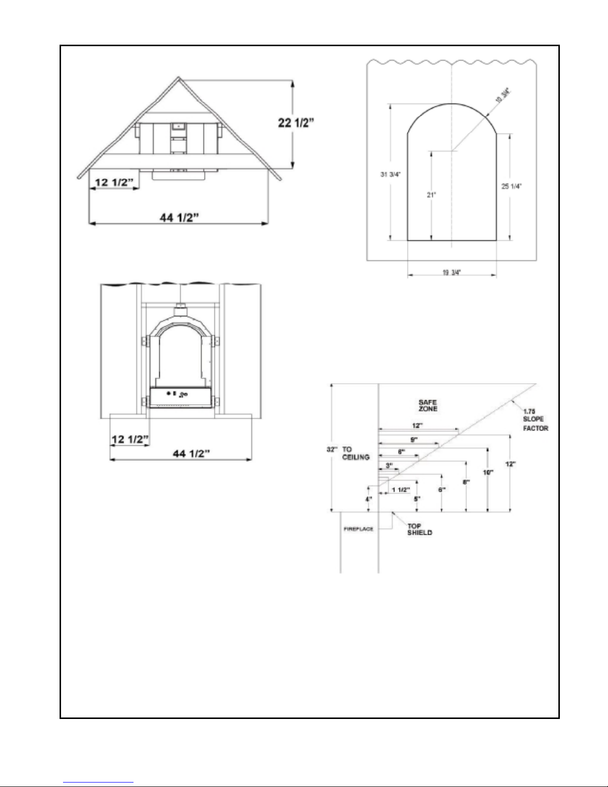
Note:
All ve
rtical measurements are from top of
fireplace opening to bottom of mantel shelf. All
Figure10- Face Opening
measurements are in inches.
Figure 9- Corner Framing
Figure11- Mantel Clearances
11
Page 12
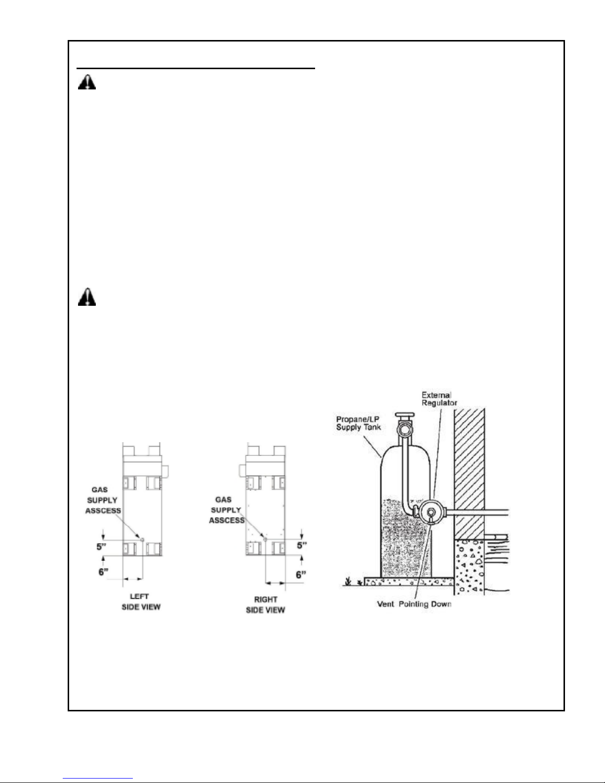
CONNECTING TO GAS SUPPLY
WARNING: A qualified technician must connect heater to gas supply. Follow all local codes.
CAUTION: Never connect heater directly to the gas supply. This heater requires an external regulator
(not supplied). The external regulator between the gas supply and heater must be installed.
INSTALLATION ITEMS NEEDED
Before installing heater, make sure you have the items listed below:
· piping (check local codes)
· sealant (resistant to propane/LP gas)
· equipment shutoff valve*
· test gauge connection**
· sediment trap
· tee joint
· pipe wrench
· flexible gas (check local code)
* A CSA design-certified equipment shutoff valve with 1/8-inch NPT tap is an acceptable alternative to test
gauge connection. Purchase the optional CSA design-certified equipment shutoff valve from your dealer.
WARNING: Never connect heater to private (non-utility) gas wells. This gas is commonly known as
wellhead gas.
The installer must supply an external regulator. The external regulator will reduce incoming gas pressure. You
must reduce incoming gas pressure to between 11 and 14 inches of water column for propane and between 5
and 10.5 inches of water column for natural gas. If you do not reduce incoming gas pressure, heater regulator
damage could occur. Install external regulator with the vent pointing down as shown in Figure 12. Pointing the
vent down protects it from freezing rain or sleet (see Figure 13).
Figure 12- Gas Line Access Into Fireplace Cabinet
Figure 13 - External Regulator With
Vent Pointing Down
12
Page 13
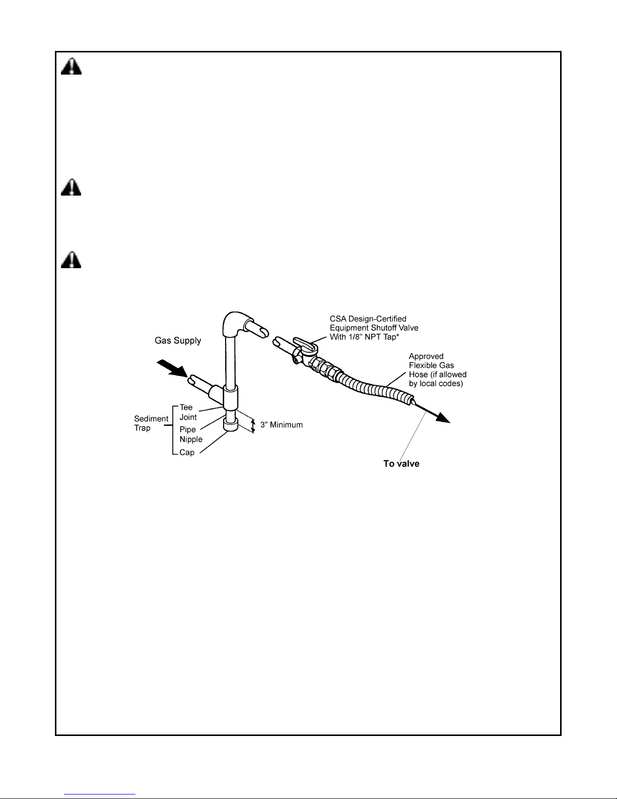
CAUTION: Use new black iron or steel pipe only. Internally tinned copper tubing may be used in certain
areas. Check your local codes. Use pipe of 1/2 inch diameter or greater to allow proper volume gas to heater.
If pipe is too small, loss of pressure will occur. Installation must include an equipment shutoff valve, union, and
plugged 1/8-inch NPT tap. Locate NPT tap within reach for test gauge hook up. NPT tap must be upstream
from heater (see Figure 14).
IMPORTANT: Install equipment shutoff valve in an accessible location. The equipment shutoff valve is for
turning on or shutting off the gas to the appliance. Apply pipe joint sealant lightly to male threads. This will
prevent excess sealant from going into pipe. Excess sealant in pipe could result in clogged heater valves.
CAUTION: Use pipe joint sealant that is resistant to gas (PROPANE or NATURAL GAS).
We recommend that you install a sediment trap in a supply line as shown in Figure 13. Place sediment trap where
it is within reach for cleaning. Install in the piping system between fuel supply and heater. Place sediment trap
where trapped matter is not likely to freeze. A sediment trap traps moisture and contaminants. This keeps them
from going into heater controls. If sediment trap is not installed or is installed incorrectly, heater may not run properly.
CAUTION: Avoid damage to regulator. Hold gas regulator with wrench when connecting into gas
piping and /or fittings. Gas supplier provide external regulator for natural gas.
*Purchase the optional CSA design-certified equipment shut off valve from your dealer. See "Accessories".
** Minimum inlet pressure for purpose of input adjustment.
Figure 14 Gas connection
13
Page 14
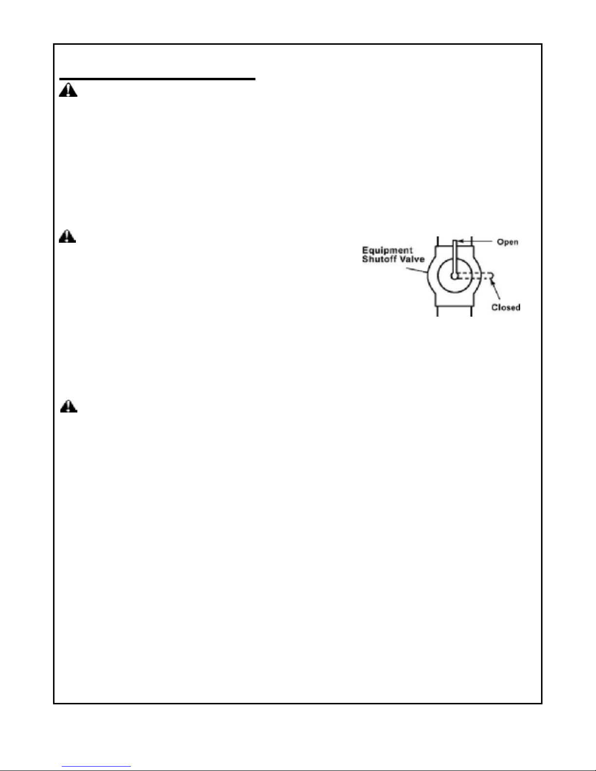
Equipment Valve
CHECKING GAS CONNECTIONS
WARNING: Test all gas piping and connections for leaks after installing or servicing. Correct all leaks immediately.
Pressure Testing Gas Supply Piping System
Test Pressures In Excess Of 1/2 PSIG(3.5kPa)
1. Disconnect heater with its appliance main gas valve (control valve) and equipment shutoff valve from gas supply
piping system. Pressures in excess of 1/2 psig will damage heater regulator.
2. Cap off open end of gas pipe where equipment shutoff valve was connected.
3. Pressurize supply piping system by either using compressed air or opening gas supply tank valve.
4. Check all joints of gas supply piping system. Apply mixture of liquid soap and water to gas joints. Bubbles
forming show a leak.
5. Correct all leaks immediately.
6. Reconnect heater and equipment shutoff valve to gas supply. Check reconnected fittings for leaks.
WARNING: Never use an open flame to check for a leak. Apply a
mixture of liquid soap and water to all joints. Bubbles forming show a
leak. Correct all leaks immediately.
Pressure Testing Heater Gas Connections
1. Open equipment shutoff valve (see Figure 15).
2. Open gas supply tank valve.
3. Make sure control knob of heater is in the OFF position.
4. Check all joints from equipment shutoff valve to control valve.
Apply mixture of liquid soap and water to gas joints. Bubbles forming show a leak.
5. Correct all leaks immediately.
6. Light heater (see Operating, page 17).Check all other internal joints for leaks.
7. Turn off heater (see To Turn Off Gas to Appliance, P18).
CAUTION: Make sure external regulator has been installed between gas supply and heater. See guidelines
under "Connecting to Gas Supply" (page 12).
Test Pressures Equal To or Less Than
1/2 PSIG (3.5 kPa)
1. Close equipment shutoff valve (see Figure 15, page 14).
2. Pressure supply piping system by either using compressed air or opening gas supply tank valve.
3. Check all joints from gas meter to equipment shutoff valve (see Figure 15).
4. Apply mixture of liquid soap and water to gas joints. Bubbles forming show a leak.
5. Correct all leaks immediately.
14
Figure 15 –
Page 15
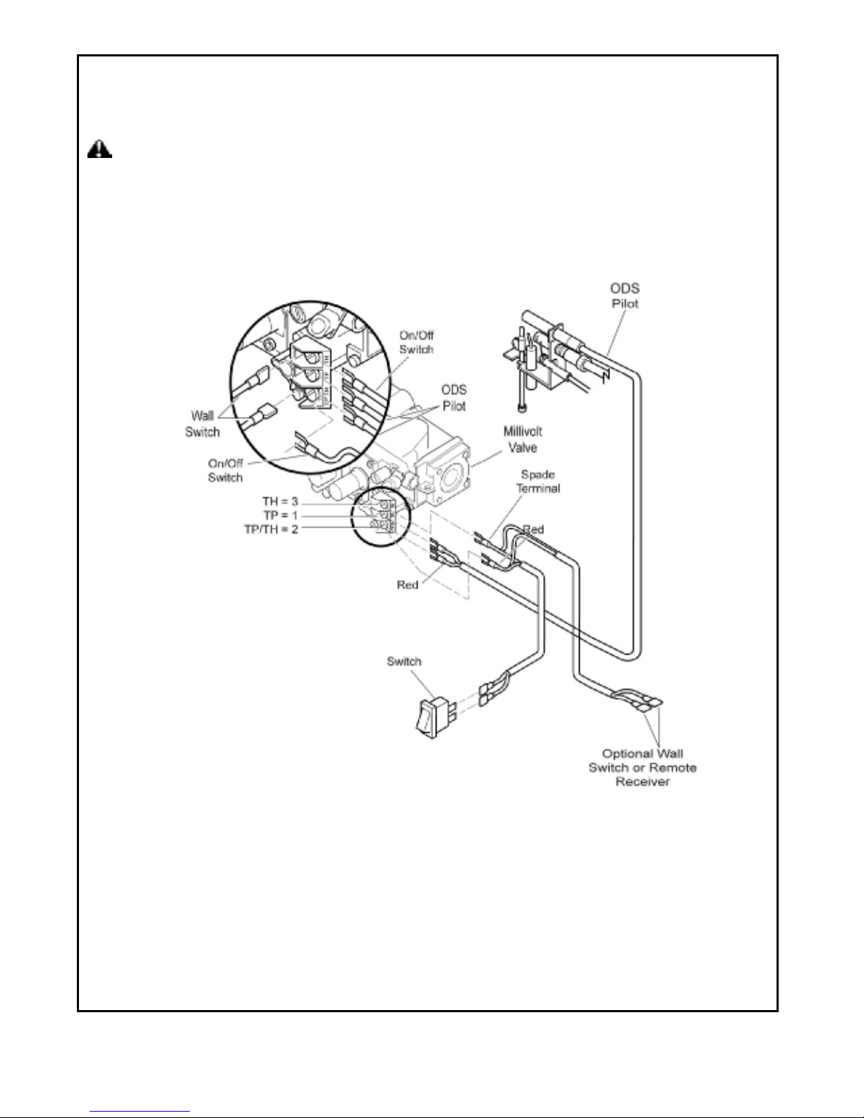
ELECTRICAL WIRING (MILLIVOLT)
CAUTION: Label all wires prior to disconnection when servicing controls. Wiring errors can cause
Improper and dangerous operation. Verify proper operation after servicing.
The millivolt valve is a self-powered combination gas control THAT DOES NOT REQUIRE 110 VAC TO
OPERATE.
Figure 16 Wiring Diagram
15
Page 16
STEP 3:
Install the log 3 on
to the two sl
ots in front plate
.
recessed hole
Insert the recessed hole in log 6 onto the
CAUTION:
no flame comes in contact with any log. With
contact any log. If so, reposition logs according
8
3.
INSTALLATION
Continued
.
WARNING: Failure to position
the parts in accordance with these
diagrams or failure to use only parts
included may result in property
damage or personal injury
periodically thereafter, check to ensure that
the heater set to High, check to see if flames
to the log installation instructions in this manual.
Flames contacting logs will create soot.
1. All logs.
Figure 20
After installation, and
Figure 1
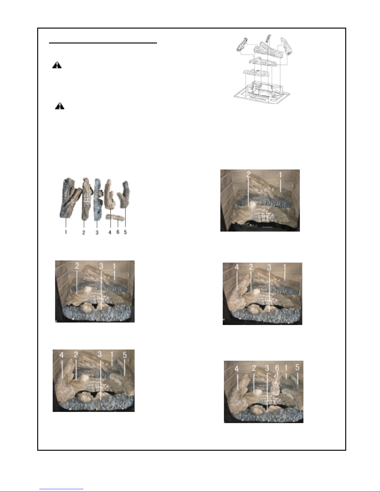
Figure 17 - Installing Log Set
IMPORTANT: Make sure logs do not cover any
burner ports. It is very important to install the logs
exactly as instructed. Do not
modify logs. Use logs supplied with heater only.
Figure 19
STEP 1: Install log 1 onto the two slots in rear plate.
STEP 2: Install log 2 onto the two slots in middle plate.
Figure 21
Figure 22
STEP 4: Insert the recessed hole on upper part of log
4 onto the pin on log 1. Place the recessed
hole on lower part of log 4 onto the pin on log
Figure 23
STEP 5: Insert the recessed hole on upper part of log
5 onto the pin on log 2. Place the
on lower part of log 5 onto the pin on log 3 .
STEP 6:
pin on log 2 and position on log 1 .
16
Page 17
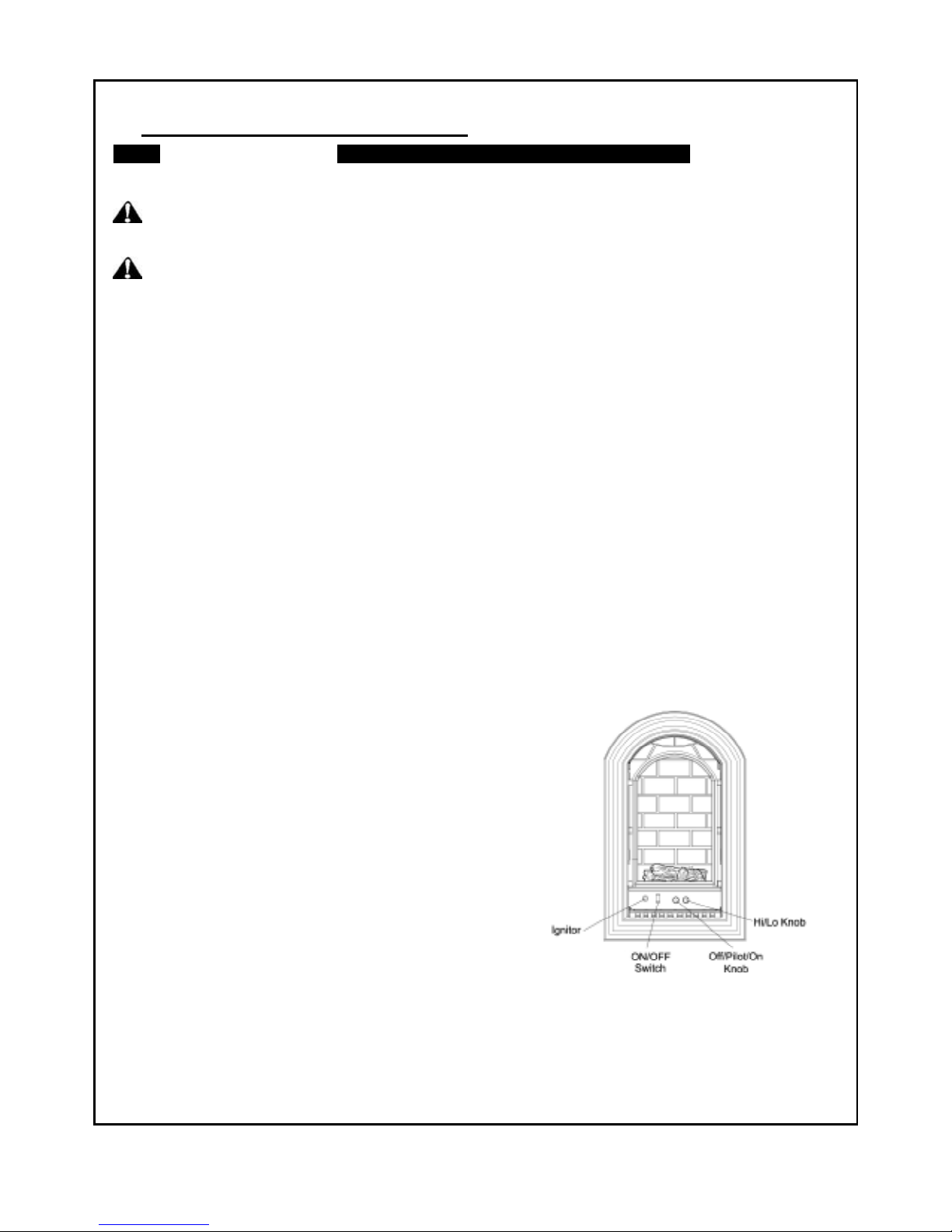
Figure 24
-
Opreating Control
WHAT TO DO IF YOU SMELL GAS
Call a qualified service technician or gas supplier. Forced or attempted repair may result in a fire or explosion.
OPERATING INSTRUCTIONS
FOR YOUR SAFETY
READ BEFORE LIGHTING
WARNING: If you do not follow these instructions exactly, a fire or explosion may result causing property
damage, personal injury or loss of life.
CAUTION: Do not try to adjust heating levels by using the equipment shutoff valve.
NOTICE: During initial operation of new heater, logs will give off a paper-burning smell. Orange flame will also
be present. Open a window to vent smell. This will only last a few hours.
A. This appliance is equipped with an ignition device which automatically lights the pilot. Do not try to light the pilot
by hand.
B. BEFORE LIGHTING smell all around the appliance area for gas. Be sure to smell next to the floor because some
Gas is heavier than air and will settle on the floor.
l Do not try to light any appliance.
l Do not touch any electrical switch; do not use any phone in your building.
l Immediately call your gas supplier from a neighbor’s phone. Follow the gas supplier’s instructions.
l If you cannot reach your gas supplier, call the fire department.
C. Use only your hand to push controls. Never use tools. If the appliance does not operate, don’t try to repair it,
D. Do not use this appliance if any part has been under water. Immediately call a qualified service technician to
inspect the appliance and to replace any part of the control system and any gas control which has been under
water.
Function of Manual Power ON/OFF Switch
Note: To operate your heater the ON/OFF switch must be
in the ON position.
17
Page 18
18
OPERATING INSTRUCTIONS
1. STOP! Read “ FOR YOUR SAFETY ” on page 17.
2. Unscrew ignitor cap and install a AAA type battery with the anode (+) pointing out. Replace cap.
3. Make sure manual shutoff valve is fully open.
4. Turn gas control knob clockwise to the "OFF" position, set the thermostat to lowest setting and turn
ON/OFF switch to OFF position.
5. Wait five (5) minutes to clear out any gas. Then smell for gas, including near the floor. If you smell gas, STOP!
Follow "B" in the safety information label. If you don't smell gas, go to next step.
6. From "OFF" position, turn the gas control knob counterclockwise to "PILOT" position. Push in control
for 5 seconds.
7. With the control knob pushed in, push in and release the ignitor button to light the pilot.
8. Continue pushing the control knob in for a further 60 seconds to prevent the flame detector from shutting off the
gas while the probe is warming up. Release the control knob.
9. Turn gas control knob counterclockwise to the ON position.
10. After the pilot has been lit for one minute, the burners can be turned on. Turn the ON/OFF switch to ON position
and adjust HI-LO knob to desired setting.
11. If the heater will not operate, follow the instructions "To Turn Off Gas To Appliance" and call your service
technician or gas supplier.
12. Wait 30 seconds before readjusting the heater when the control knob has been turned down to a lower setting.
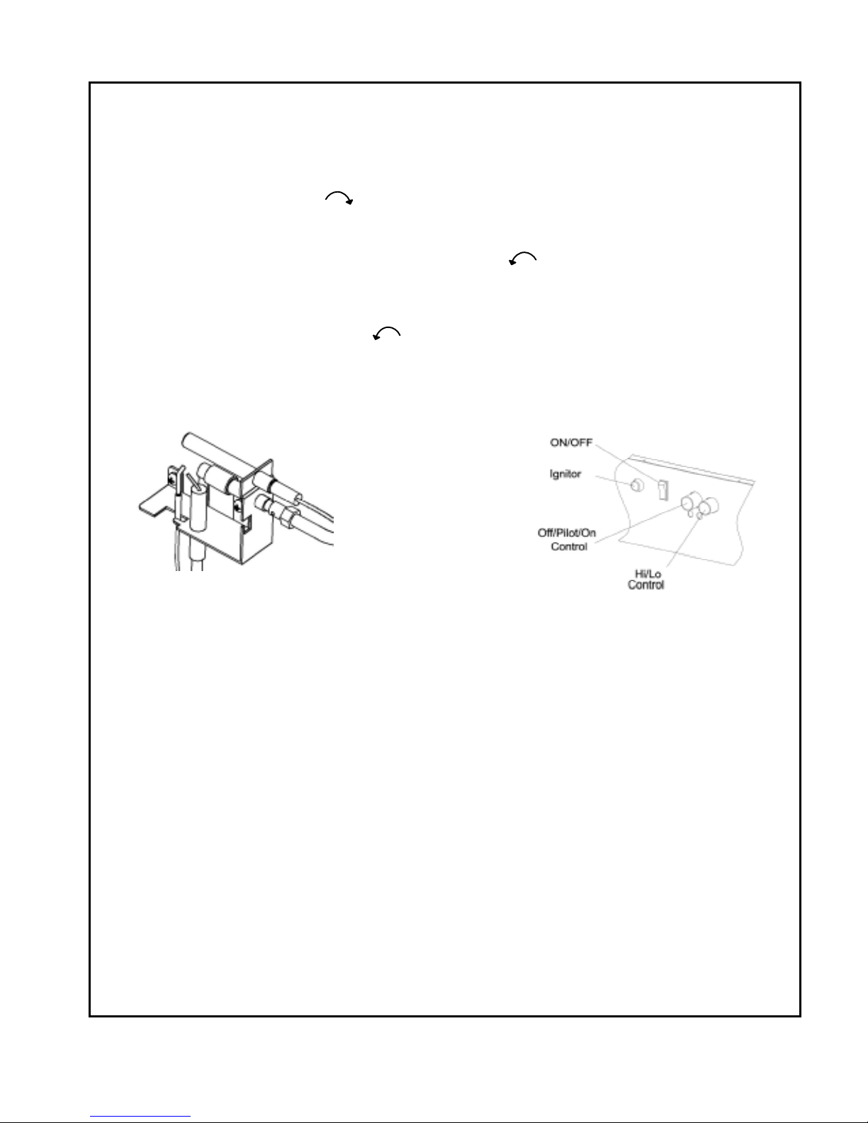
Figure 25-Pilot Figure 26-Control Plate
TO TURN OFF GAS TO APPLIANCE
Push in gas Control Knob slightly and turn clockwise to the OFF position. Do not force.
MANUAL LIGHTING PROCEDURE
(match light)
1. Remove front panel .
2. Follow steps 1 through 5 under OPERATING INSTRUCTIONS.
3. With Control Knob in PILOT position, strike match, and hold near pilot. Press in Control Knob, pilot
should light.
4. Keep Control Knob pressed in for 30 seconds after lighting pilot. After 30 seconds, release Control Knob. Follow
step 9 under OPERATING INSTRUCTIONS.
Page 19
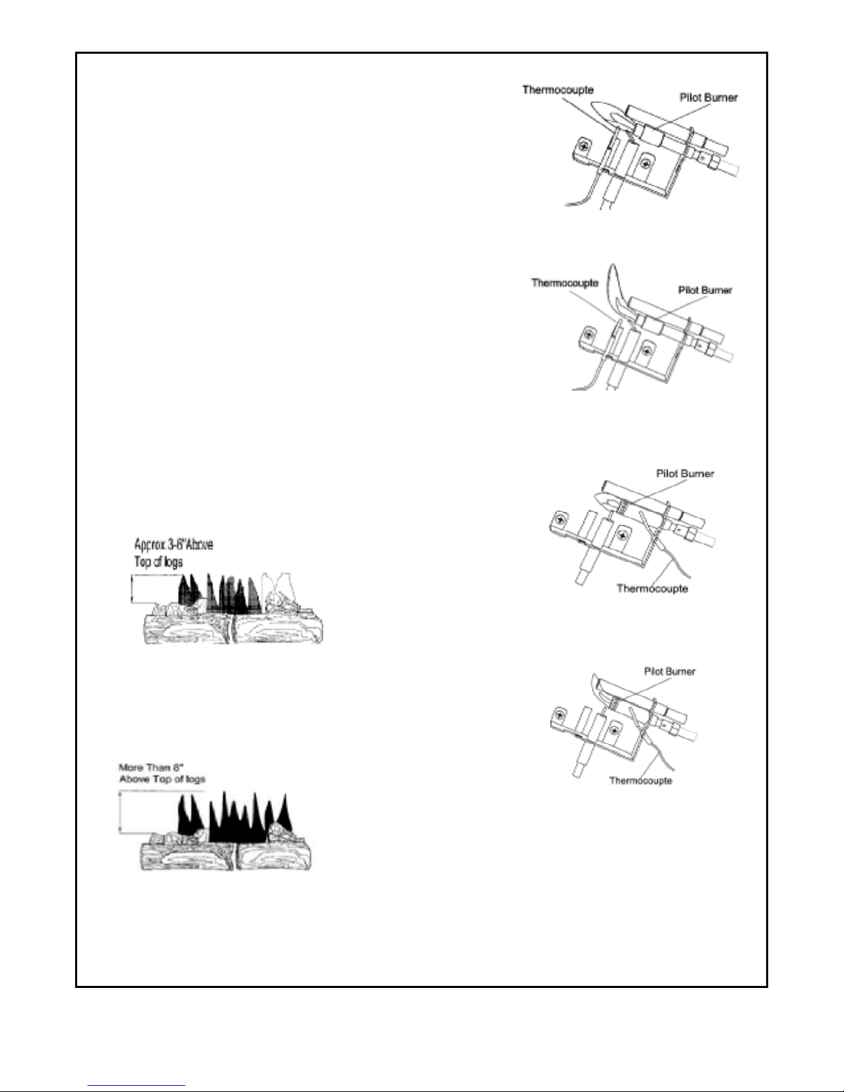
Figure 29
-
Correct Pilot Flame
Figure 30
-
Incorrect Pilot Flame
INSPECTING BURNERS
Check pilot flame pattern and burner flame patterns often.
PILOT FLAME PATTERN
1. Turn control knob to pilot position
2. Inspect pilot flame and refer to Figure 27 and 28.
· Figure 27 shows a correct pilot flame pattern.
· Figure 28 shows an incorrect pilot flame pattern. The
incorrect pilot flame is not touching the thermocouple. This
will cause the thermocouple to cool. When the thermocouple cools,
the heater will shut down.
· If the pilot flame is incorrect, as shown in Figure 28.
Turn heater off (see To Turn Off Gas to Appliance, page 18)
See troubleshooting, page 21.
BURNER FLAME PATTERN
· Figure 31 shows a correct burner flame pattern.
· Figure 32 shows an incorrect burner flame pattern.
If burner flame is incorrect:
Turn heater off (see To Turn Off Gas to Appliance, page 18)
see Troubleshooting, Page 21.
Figure 31- Correct Flame Pattern
with Control Knob Set to High
Flame (5)
Figure 32 -Incorrect Flame
19
Pattern with Control Knob Set to
High (5)
Figure 27 -Correct Pilot Flame
Pattern- ANI model
Figure 28- Incorrect Pilot Flame
Pattern- ANI model
Pattern- ALI model
Pattern- ALI model
Page 20
CLEANING AND MAINTENANCE
WARNING: Failure to keep primary air openings of burners clean may result in sooting and property
damage.
CAUTION: You must keep control areas, burner, and circulating air passageways of heater clean.
Inspect these areas of heater before each use. Have heater inspected yearly by a qualified service
person. Heater may need more frequent cleaning due to excessive lint from carpeting, bedding material,
pet hair, etc.
CLEANING ODS/IGNITOR AND BURNER
Clean with a vacuum cleaner.
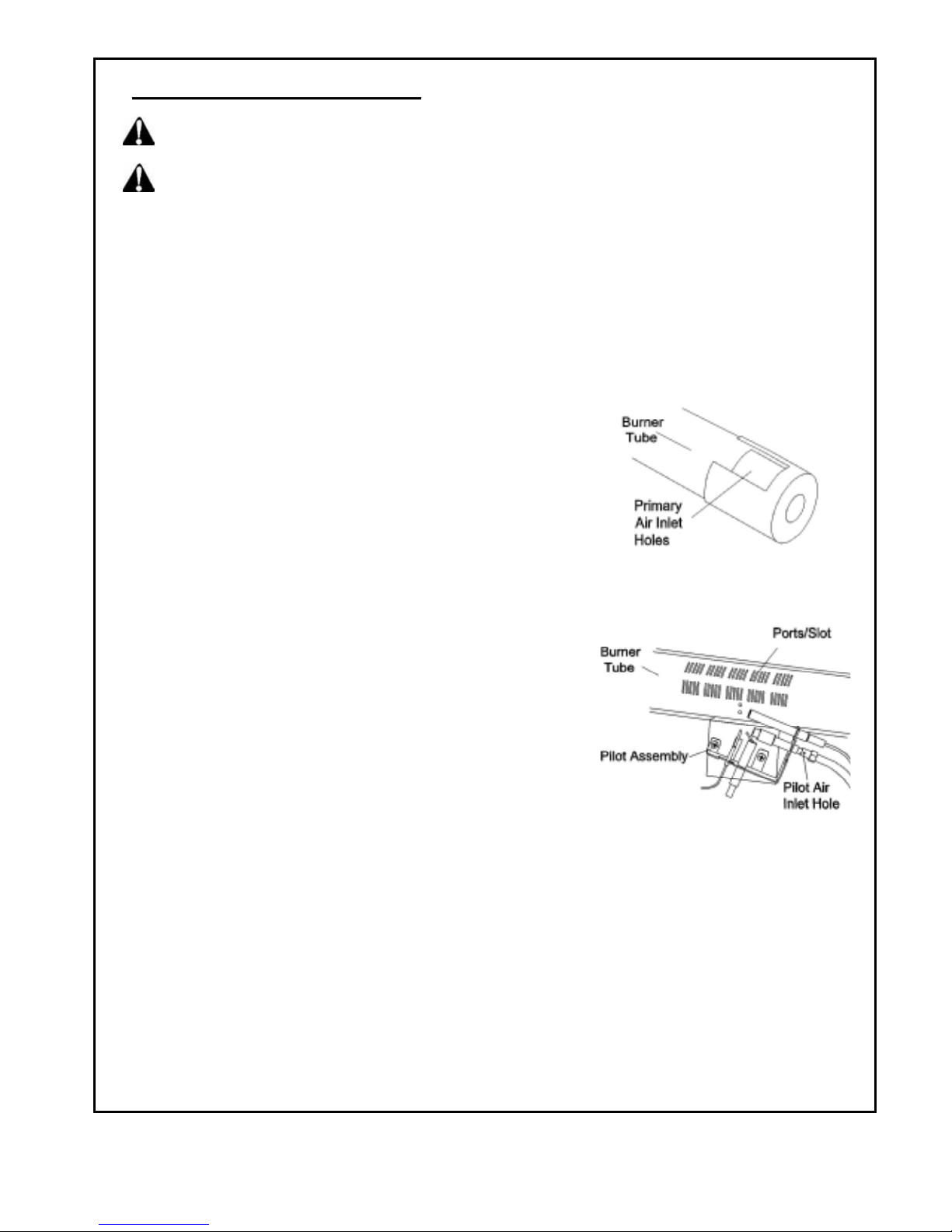
CLEANING BURNER INJECTOR HOLDER AND PILOT AIR INLET HOLE
We recommend that you clean the unit every three months or after 2500 hours of operation. We also
recommend that you keep the burner tube and pilot assembly clean and free of dust and dirt. To clean these
parts we recommend using compressed air no greater than 30 PSI. You can use a vacuum cleaner in the
blow position. If using compressed air in a can, please follow the directions on the can. If you don't follow
directions on the can, you could damage the pilot assembly.
1. Shut off the unit, including the pilot. Allow the unit to cool for
at least thirty minutes.
2. Inspect burner, pilot and primary air inlet holes on injector
holder for dust and dirt (see Figure 32).
3. Blow air through the ports/slots and holes in the burner.
4. Check the injector holder located at the end of the burner
tube again. Remove any large particles of dust, dirt, lint, or
pet hair with a soft cloth or vacuum cleaner nozzle.
5. Blow air into the primary air holes on the injector holder.
6. In case any large clumps of dust have now been pushed into Figure 32 – Injector holder on
the burner. Repeat steps 3 and 4. Clean the pilot assembly also. Outlet Burner Tube
A yellow tip on the pilot flame indicates dust and dirt in the pilot
assembly. There is a small pilot air inlet hole about two inches
from where the pilot flame comes out of the pilot assembly
(see Figure 33). With the unit off, lightly blow air through the air
inlet hole. You may blow through a drinking straw if compressed
air is not available.
CABINET
• Air Passageways
• Use a vacuum cleaner or pressurized air to clean.
the cabinet to remove dust.
LOGS
• If you remove logs for cleaning, refer to Installing Logs (page 16)
for proper log placements. Figure 33 – Pilot Air Inlet Hole
• Replace logs if broken or chipped (dime-sized or larger).
MAIN BURNER
Periodically inspect all burner flame holes with the heater running. All slotted burner flame holes should
be open with yellow flame present. All round burner flame holes should be open with a small blue flame
Present. Some burner flame holes may become blocked by debris or rust, with no flame present. If so, turn off
heater and let cool, either remove blockage or replace burner. Blocked burner flame holes will create soot.
20
•
Page 21
Ignitor electrode is not connected
TROUBLESHOOTING
NOTE:
on position. Please wait for one minute to allow valve to reset.
Turn the control knob to "off" position first and wait for one minute. Then turn the control knob to
WARNING:
•Shut off gas supply.
•Do not try to light any appliance.
•Do not touch any electrical switch; do not use any phone in your building.
• Immediately call your gas supplier from a neighbor’s phone. Follow the gas supplier’s instructions.
• If you cannot reach your gas supplier, call the fire department.
WARNING:
WARNING
fireplace.
CAUTION:
OBSERVED PROBLEM
When ignitor button is pressed in,
there is no spark at ODS/pilot
When ignitor button is pressed in,
there is a spark at ODS/pilot but
no pilot flame present.
ODS/pilot lights but flame goes out
when control knob is released.
.
If you smell gas
Make sure that power is turned off before proceeding.
: Turn off and let cool before servicing. Only a qualified service person should service and repair
Never use a wire, needle, or similar object to clean ODS/pilot. This can damage ODS/pilot unit.
POSSIBLE CAUSE REMEDY
1. Ignitor is positioned wrong.
2. Ignitor electrode is broken.
3.
to ignitor cable.
4. Ignitor cable is pinched.
5. Damaged ignitor cable.
6. Bad piezo ignitor.
7. Low battery.
1. Gas supply is turned off or
equipment shutoff valve is
closed.
2. Control knob not fully pressed in
while pressing ignitor button.
3. Air in gas lines (new installation
or recent gas interruption).
4. ODS/pilot is clogged.
5. Incorrect inlet gas pressure or
regulator is damaged.
6. Depleted gas supply
1. Control knob is not fully pressed
in.
2. Control knob is not pressed in
long enough.
3. Equipment shutoff valve is not
fully open.
4. Thermocouple connection is
loose.
5. Thermocouple damaged
6. Control valve damaged.
21
Replace ignitor.
1.
Replace ignitor..
2.
Reconnect ignitor cable.
3.
Free ignitor cable if pinched by
4.
any metal or tubing.
Replace ignitor cable.
5.
6. Replace piezo ignitor.
7. Replace battery.
1. Turn on gas supply or open
equipment shutoff valve.
2. Fully press in control knob while
pressing ignitor button.
3. Continue holding down control
knob for 30 seconds to remove
air. Repeat igniting operation
until air is removed.
4. Clean ODS/pilot (see Cleaning
and Maintenance Page 20) or
replace ODS/pilot assembly.
5. Check inlet gas pressure or
replace gas valve.
6. Contact local propane/LP Gas
Company
1. Press in control knob fully.
2. After ODS/pilot lights, keep
control knob pressed in 30
seconds.
3. Fully open equipment shutoff
valve.
4. Hand tighten until snug, and then
tighten ¼ turn more.
5. Replace pilot.
6. Replace control valve.
Page 22
Dirty or partially clogged burner
2
2
TROUBLESHOOTING
(Continued)
OBSERVED PROBLEM POSSIBLE CAUSE REMEDY
Burner(s) does not light after
ODS/pilot is lit.
Delayed ignition of burner(s).
1. Burner orifice is clogged.
2. Burner orifice diameter is too
small.
3. Inlet gas pressure is too low.
.
1. Manifold pressure is too low.
2. Burner orifice is clogged.
Burner backfiring during combustion.
High yellow flame during burner
combustion.
1. Burner orifice is clogged or
damaged.
2. Burner is damaged.
3. Gas regulator is damaged.
1. Dirty or clogged burner.
2. Gas regulator is defective.
3. Inlet gas pressure is too low.
Slight smoke or odor during initial
operation
Heater produces a whistling noise
when burner is lit.
1. Residues from manufacturing
process.
1. Turning control knob to HI
position when burner is cold.
2. Air in gas line.
3. Air passageways on heater are
blocked.
4.
orifice.
Heater produces a clicking/ticking
noise just after burner is lit or
shut off.
White powder residue forming within
burner box or on adjacent walls or
furniture
1. Metal is expanding while heating
or contracting while cooling.
1. When heated, the vapors from
furniture polish, wax, carpet
cleaners, etc., turn into white
powder residue.
1. Burner orifice (see Cleaning
and maintenance Page 20) or
replace burner orifice.
2. Replace burner orifice.
3. Contact your gas supplier.
1. Contact your gas supplier.
2. Clean burner (see Cleaning
and maintenance Page 20) or
replace burner orifice.
1. Clean burner orifice (see
Cleaning and maintenance
Page 20) replace.
2. Contact Dealer or Customer
Service.
3. Replace gas valve.
1. Check burner for dirt and debris.
If found, clean burner (see
Cleaning and Maintenance
Page 20).
2. Replace gas valve.
3. Check inlet pressure.
1. Problem will stop after a few
hours of operation.
1. Turn control knob to LO position
and let warm up for a minute.
2. Operate burner until air is
removed from line. Have gas
line checked by local
propane/LP Gas Company.
3. Observe minimum installation
clearances (Figure 5, page 9)
4. Clean burner (see Cleaning and
Maintenance Page 20) or
replace burner orifice.
1. This is common with most
heaters. If noise is excessive,
contact qualified service
technician.
1. Turn heater off when using
furniture polish, wax, carpet
cleaner or similar products.
Page 23

When ignitor button
is pressed in,
1. Ignitor is positioned wrong.
2. Ignitor electrode is broken.
3. Ignitor electrode is not connected to
ignitor cable.
4. Ignitor cable is pinched or wet.
5. Broken ignitor cable.
6. Bad piezo ignitor.
1.Replace ignitor.
2.Replace pilot.
3.Reconnect ignitor cable.
4.Free ignitor cable if pinched by any metal
or tubing. Keep ignitor cable dry.
5.Replace ignitor cable.
6.Replace piezo ignitor.
When ignitor button
is pressed in, there
is no spark at
ODS/pilot.
ODS/pilot lights but
flame goes out
when control knob
is released
1.Gas supply is turned off or equipment
shutoff valve is closed.
2.Control knob not fully pressed in while
pressing ignitor button.
3. Air in gas lines when installed.
4.ODS/pilot is clogged.
5.Gas regulator setting is not correct.
6.Bad piezo ignitor.
7.Depleted gas supply.
1.Control knob is not fully pressed in.
2.Control knob is not pressed in long
enough.
3.Equipment shutoff valve is not fully open.
4.Thermocouple connection is loose at the
control valve.
5.Thermocouple damaged.
6.Control valve damaged.
1.Turn on gas supply of open equipment
shutoff valve.
2.Fully press in control knob while
pressing ignitor button.
3.Continue holding down control knob.
Repeat igniting operation until air is moved.
4.Clean ODS/pilot (see Cleaning and
Maintenance Page 20) or replace
ODS/pilot assembly.
5.Replace gas valve.
6.Replace ignitor.
7.Contact your local gas company.
1.Press in control knob fully.
2. After ODS/pilot lights, keep control knob
pressed in 30 seconds.
3.Fully open equipment shutoff valve.
4.Hand tighten until snug, and then tighten
1/4 turn more.
5.Replace pilot.
6.Contact Dealer or Customer Service.
REPLACEMENT PARTS
REPLACEMENT PARTS
When calling Customer Service, or your dealer, have ready:
NOTE: Use only original replacement parts. Your Name
This will protect your warranty coverage Your Address
for parts replaced under warranty. Mode and serial numbers of your heater
How heater was malfunctioning
PARTS UNDER WARRANTY Type of gas used (propane/LP or NG)
Contact authorized dealers of this product. Purchase date
If they can’t supply original replacement parts, Warranty card
call Customer Service toll free number at Usually, we will ask you to return
(1-877-886-5989) for referral information.
PARTS NOT UNDER WARRANTY When calling Customer Service, have ready
Contact authorized dealers of this product. Model number of your heater
If they can’t supply original replacement part(s), The replacement part number
Call Customer Service toll free number at
(1-877-886-5989) for referral information.
23
Page 24
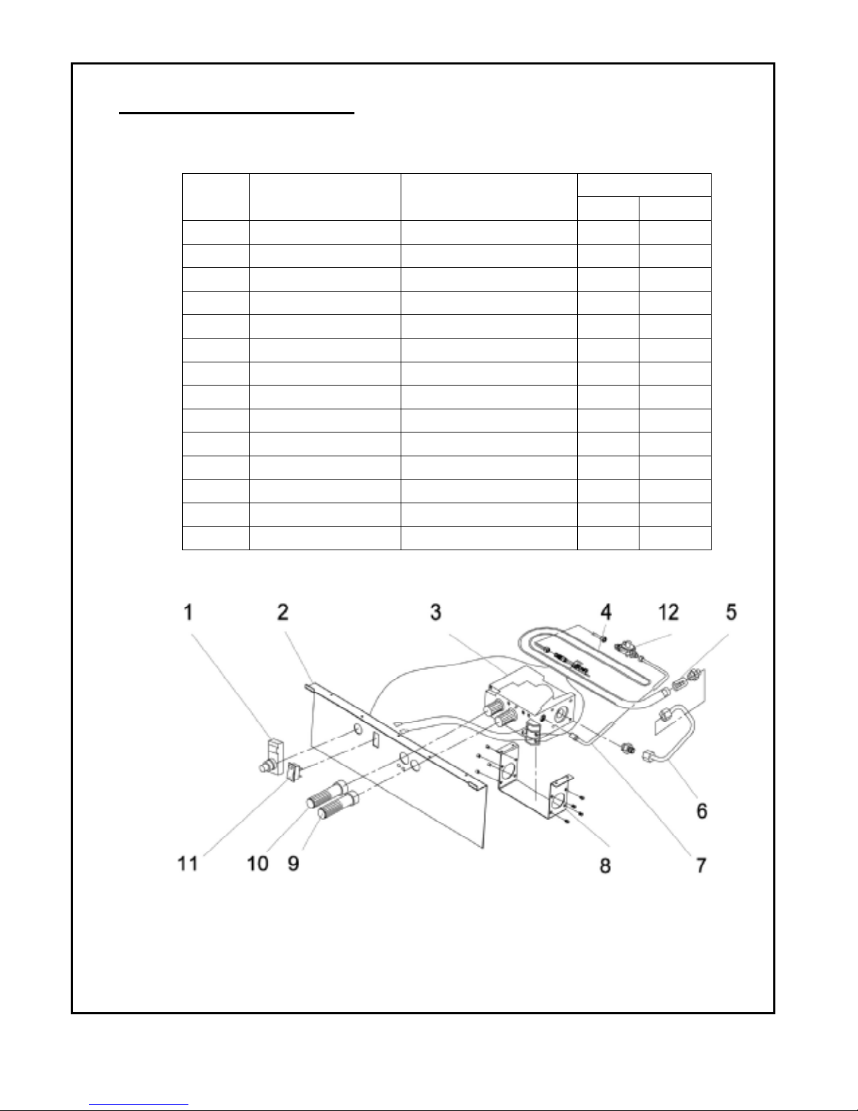
ANI & ALI PARTS LIST
This list contains replaceable parts used in your heater. When ordering parts, follow the instructions listed
under Replacement Parts on page 23 of this manual.
24
KEY NO
1 AL092-01 Ignitor 1 1
2 AN/LI200MV-205 Control Panel 1 1
3 MV0.820.636
3 MV0.820.637
4 AN/LI200MV-230 Burner Assembly 1 1
5 AN/LI200MV-234 Inlet 1 1
6 AN/LI200MV-240 Outlet Tube Assembly 1 1
7 AN/LI200MV-239
7 AN/LI200MV-240
8 AN/LI200MV-204 MV Valve Bracket 1 1
9 AN/LI200MV-209 HI/LO Knob 1 1
10 AN/LI200MV-209 OFF/PILOT/ON Knob 1 1
11 VL067-01 Switch 1 1
12 NRV81F1-3 Regulator 1
PART NUMBER DESCRIPTION
ODS INTLET TUBE(LP)
ODS INTLET TUBE(NG)
MV Valve-ALI
MV Valve-ANI
QUANTITY
ANI ALI
1
1
1
1
Page 25
25
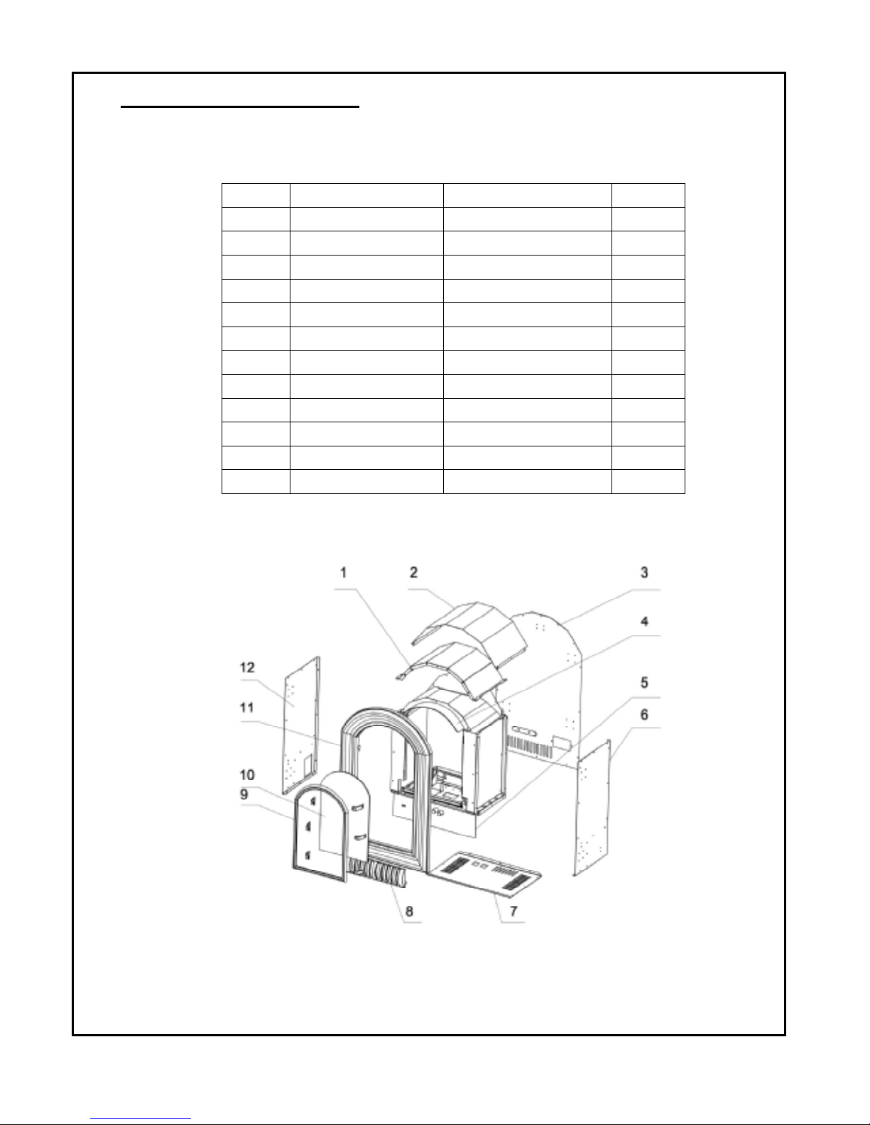
PARTS LIST
This list contains replaceable parts used in your heater. When ordering parts, follow the instructions listed
under Replacement Parts on page 23 of this manual.
ANI
ALI
KEY NO
1 AN/LI200MV-221 Top Reflector 1
2 AN/LI200MV-101 Top Cover Board 1
3 AN/LI200MV-104 Back Cover Board 1
4 AN/LI200MV-110 Top Board Assembly 1
5 AN/LI200MV-205 Control Panel 1
6 AN/LI200MV-102 Right Side 1
7 AN/LI200MV-105 Bottom 1
8 AN/LI200MV-141 Access Door 1
9 AN/LI200MV-122 Glass Frame 1
10 AN/LI200MV-124 Glass 1
11 AN/LI200MV-121 Front Panel Frame 1
12 AN/LI200MV-103 Left Side 1
PART NUMBER DESCRIPTION QUALITY
 Loading...