

HearthRite HR15ML-1, HR25ML-1, HR15TL-1, HR25TL-1 Owner's Operation And Installation Manual
OWN E R’S OP E R ATIO N A N D I NSTA L L ATIO N M A NUAL
WA R N I N G : I m p r o p e r i n s t a l l a t i o n ,
adjustment, alteration, service or maintenance
can cause injury or property damage. Refer to
this manual for correct installation and operational procedures. For assistance or additional information consult a qualified installer,
service agency, or gas supplier.
This appliance may be installed in an aftermarket* perm a nent l y l ocate d , m anuf a ctur e d
(mobile) home, where not prohibited by local
codes.
This appliance is only for use with the type of
gas indica ted on the rat ing plate. This
appliance is not convertible for use with other
gases.
*Aftermarket: Completion of sale, not for purpose of
resale, from the manufacturer.
Do not store, or use gasoline or other flammable
vapors and liquids in the vicinity of this or any
other appliance.
WHAT TO DO IF YOU SMELL GAS
! Do not try to light any appliance.
! Do not touch any electrical switch; do not
use any phone in your building.
! Immediately call your gas su pp li er from a
neighbor’s phone. Follow the gas supplier’s
instructions.
! If you cannot reach y our gas supplier, call
the fire department.
Installation and service must be performed by a
q u a l i f i e d i n s t a l l e r , service ag e n c y o r g a s
supplier.
HR15TL-1
HR25TL-1
HR15ML-1
HR25ML-1
Table of Contents
Important Safety Information.................................2
Product Features.....................................................3
Proper Ventilation & Fresh Air..............................4
Installation................................................................6
Operating Your Heater............................................10
Cleaning & Maintenance.......................................13
Trouble Shooting...................................................14
Specifications..........................................................17
Parts List..................................................................19
Warranty Information............................................26
WA RNING: If t he i nformatio n in this
manual is not followed exactly, a f i r e o r
explosion may result causing property
damage, personal injury, or loss of life.
WARNING: This is an unvented gasfired heater. It uses air (oxygen) f r o m t h e
r o o m i n w h i c h i t i s inst alled. Provisions for adequate combustion and ventilation air must be provided. Refer t o Air
Fo r Combustion and Ventilation section on
page 4 of this manual.
WATER VAPOR: A BY-PRODUCT OF UNVENTED ROOM
HEATERS
Water vapor is a by-product of gas combustion. An
unvented room heater productes approximately one (1)
ounce (30ml) of water for every 1,000 BTU’s (.3KW’s) of
gas input per hour. Refer to page 3.
Installer: Please leave these instructions with the
consumer.
Consumer: Please retain these instructions for
future use.
INFRARED VEN T -FRE E
PROPANE/LP G AS
SPACE HE ATE R
A Division of Empire Comfort Systems,Inc.
918 Freeburg Avenue
Phone : 618-233-7420 or 1-800-851-3153
Fax : 618-233-7097 or 1-800-443-8648
www.hearthrite.com
Belleville,IL 62220
IMPORTANT
WARNINGS
I M P O R TANT: R ead t h i s
o wner ’ s m an u a l c a r e f ully a nd
c o mp l e te l y b e f o re t r y i n g t o
a s s e m b l e, o pe ra te, o r s er vi ce
t h i s h e a t e r . I mp ro p e r u se o f
thi s he a ter ca n ca u se s eri o us
i n j u r y o r d e a t h f r o m b u r n s ,
f i r e , e x p l o s i o n , e l e c t r i c a l
s h o c k, a nd c a r b o n m o n o x i d e
poisoning.
Do not place clothing or other
flammable material on or near
the appliance. Never place any
objects on the heater.
Due to high temperatures, heater
s h ou l d b e k ep t o u t o f
traffic and away from furniture
and draperies.
Surf a c e of heat e r bec o m es
very hot when running hea ter.
Keep children and adults away
from hot surface to avoid burns
or clothing ignition. Heater will
remain hot for a time after shut
dow n. All ow surf ace to coo l
before touching.
C a r e f u l l y s u p e r v i s e y o u n g
children when they are in the
same room with heater.
Mak e su re g ril l guar d is i n
place before running the heater.
10. Before using furniture polish,
wax, carpet cleaner, or similar
products, turn heater off. If
heated, the vapors from these
products may create a white
powder residue within burner
box or on adjacent walls or
furniture.
11. Do not use heater if any part
has been under water.
Immediately call a qualified
service technician to inspect
the room heater and to
replace any part of the control
system and any gas control
which has been under water.
12. Turn off heater and let cool
before servicing. Only a qualified
service person should service
and repair heater.
13. Operating heater above
elevations of 4,500 feet could
cause pilot outage.
14. To prevent performance
problems, do not use
propane/LP fuel tank of less
than 100 lbs. capacity.
DANGER: Carbon monoxide
poisoning may lead to death!
Carbo n Monoxide Poisoning:
Early signs of carbon monoxide
poisoning resemble the flu with
headaches, dizziness, or nausea.
If you have these signs, the heater
may not be working properly. Get
fresh air at once! Have heater
serviced. Some people are more affected by carbon monoxide than
ot he rs. These in clude pr eg nant
women, persons with heart or lung
disease or anemia, those under the
influence of alcohol, a nd those
at high altitudes.
Propane/LP Gas: Propane/LP gas
is odorless. An odor-making agent
is added to Propane/LP gas. The
o d o r h e lp s y ou d e te c t a
Propane/LP gas leak . However,
the odor added to Propane/LP gas
can fade. Propane/LP gas may be
present even though no odor exists.
Make certain you read and understand
all warnings. Keep this manual for
reference. It is your guide to safe and
pr oper operation of thi s h eater .
WARNING: Do not use any
a c c e s s o r y n o t a pp roved f or
use with this heater.
WARNING: A ny change to
thi s he ate r or its cont rol s ca n
be dangerous.
Keep the appliance area clear
and f r ee f r om c o m bustibl e
mat eri als, ga sol ine , an d ot her
fl am ma bl e vapors a nd liquids.
SAFETY INFORMATION
1. This appliance is only for use
with the type of gas indicated
on the rating plate. This
appliance is not convertible for
use with other gases.
2. Do not place propane/LP
supply tank(s) inside any
structure. Locate propane/LP
supply tank(s) outside.
3. If you smell gas
Shut off gas supply.
!
! Do not try to light any appliance.
Do not touch any electrical switch,
!
do not use any phone in your
building.
! Immediately call your gas supplier
from a neighbor’s phone. Follow
the gas supplier’s instructions.
! If you cannot reach your gas
supplier, call the fire department.
4. This heater shall not be
installed in a bedroom or
bathroom
5. Always run heater with control
knob at LOW or HIGH locked
positions. Never set control
knob between locked positions.
Poor combustion and higher
levels of carbon monoxide may
result.
6. This heater needs fresh,
outside air ventilation to run
properly. This heater has an
Oxygen Depletion Sensor
(ODS) safety shutoff system.
The ODS shuts down the
heater if not enough fresh air
is available. See
Combustion and Ventilation
pages 4 and 5.
7. Keep all air openings in front
and bottom of heater clear
and free of debris. This will
insure enough air for proper
combustion.
8. If heater shuts off. Do not
relight until you provide fresh,
outside air. If heater keeps
shutting off, have it serviced.
9. Do not operateT
! where flammable liquids or va pors are used or stored
! under dusty conditions
Fresh Air for
2

Heater
Cabinet
Control
Knob
Grill
Burners
Ignitor
Button
Lo we r
Front
Panel
LOCAL CODES
Install and use heater with care. Follow all local
codes. In the absence of local codes, use the
latest edition of
National Fuel Gas Code ANSZ223.
1
,
also known as NFPA 54*.
*Available from :
American National Standards Institute, Inc.
1430 Broadway
New York, NY 10018
National Fire Protection Association, Inc.
Batterymarch Park
Quincy, MA 02269
QUALIFIED INSTALLING AGENCY
Installation and replacement of gas piping, gas
utilization equipment or accessories and repair
and servicing of equipment shall be performed only
by a qualified agency. The term “qualified agency”
means any individual, firm, corporation, or company that either in person or through a representative is engaged in and is responsible for (a)
the installation, testing, or replacement of gas piping
or (b) the connection, installation, testing, repair, or
servicing of equipment ; that is experienced in such
work; that is familiar with all precautions required,
and that has complied with all the requirements of
the authority having jurisdiction.
State of Massachsetts: The installation must be
made by a licensed plumber or gas fitter in the
Commonwealth of Massachusetts .
Sellers of unvented propane or natural gas-fired
supplemental room heaters shall provide to each
purchaser a copy of 527 CMR 30 upon sale of the
unit.
In the state of Massachusetts, unvented propane or
nature gas-fired space heaters shall be prohibited in
bedrooms and bathrooms.
UNPACKING
1. Remove heater from carton.
2. Remove all protective packaging applied to
heater for shipment.
3. Check heater for any shipping damage. If heater
is damaged, promptly inform dealer where you
bought heater.
PRODUCT FEATURES
Figure1-Vent-Free Propane/LP Gas Heater
SAFETY DEVICE
A standar d requirement f or all vent- free room
heaters. This heater has a pilot with an Oxygen
Depletion Sensor(ODS) safety shutoff system.
The ODS/pilot shuts off the heater if there is
not enough fresh air.
PIEZO IGNITION SYSTEM
This heater is equipped with a piezo ignitor.
This system requires no matches, batteries, or
other sources to light heater.
THERMOSTATIC HEAT
CONTROL ON THERMOSTAT
MODELS
These heaters have a control valve with a
thermostat se nsing bu lb. This results in the
greatest heater c om fort and may resu lt in
lower gas bills.
WATER VAPOR: A BY-PRODUCT OF UNVENTED ROOM HEATERS
Water vaporis a by-product of g as combusti on.An
unvented room heater productes approximately one (1)
ounce (30ml) of water for every 1,000 BTU’s (.3KW’s) of
gas input per hour.
Unve n t ed roo m h e ater s a r e reco m m ended a s
supplemental heat (a room) rather than a primary heat
source (an entire house) .In most supplemental heat
application, the water vapor does not create a problem.
In most applications, the water vapor enhances the low
humidity atmosphere experienced during cold weather.
The following steps will help insure that water vapor
does not become a problem.
1. Be s ur e the heater is sized proper ly for th e
applica tion, including ample combusion a ir and
circulation air.
2. If high humidity is experienced, a dehumidifier may
be used to help lower the water vapor content of the
air.
3. Do not use an unvented room heater as the primary
heat source.
3
FRESH AIR FOR
PROVIDING ADEQUATE
VENTILATION
The following are excerpts from
National Fuel Gas Code. NFPA
54/ANS Z223.1, Section 5.3.
Air for
Combustion and Ventilation. All
spaces in homes fall into one of
the three following ventilation
classifications:
1. Unusually Tight Construction
2. Unconfined Space
3. Confined Space
The information on pages 4
through 6 will help you classify
your space and provide adequate
ventilation.
WARNING: This heater
sha ll n ot b e in sta lle d in a
co nf in ed sp ac e or un us ua ll y
tigh t co n s truc t ion u nles s
provi sio ns a re p ro vid ed f or
ade qua te c omb ust ion and
ventilatio n a i r . R e a d t h e
f o l l ow ing i ns tru c t i o ns t o
insure proper fresh air for this
and ot h er f uel- b urn i ng
appliances in your home.
Confined and
Unconfined Space
The National Fuel Gas Code ANS
Z223.1
defines a confined space
as a space whose volume is less
than 50 cubic feet per 1,000 Btu per
hour ( 4 . 8 m
3
per kw) o f t h e
aggre gat e in put rating of a ll
appliances installed in that space
and an unconfined space as a
space whose volume is not less
than 50 cubic feet per 1,000 Btu per
hour ( 4.8 m
3
per k w) of the
aggre gat e in put rating of a ll
appliances installed in that space.
Rooms communicating directly with
t h e s p a ce i n w h ich t h e
appliances are installed*, through
openings not furnished with doors,
ar e consi de red a par t of the
unconfined space.
This heater shall not be installed
in a confined space or unusually
t i gh t c on s t r u c ti o n u nl e s s
prov i s i ons ar e p r ovide d f o r
ade qua t e com bus t ion an d
ventilation ai r.
*
A d j o i n i n g r o o m s a r e
communicating only if there are
doorless passageways or ventilation grills between them.
WARNING: If the area in which the heater may be operated is smaller than that defined as an
unconfined space or if the building is of unusually tight construction, provide adequate combustion and
ventilation air by one of the methods described in the National Fuel Gas Code, ANS Z223.1, Section 5.3
or applicable local codes.
Unusually Tight Construction
The air that leaks around doors and
windows may provide enough fresh
air for combustion and ventilation.
However, in buildings of unusually
tight construction, you must provide
additional fresh air.
Unusually tight construction is
defined as construction where:
a. walls and ceilings exposed to
the outside atmosphere have a
continuous water vapor retarder
with a rating of one perm (6
×
10
-11
kg
per pa-s ec- m2) o r le ss with
openings gasketed or sealed
and
b. weather stripping has been
ad ded on ope na bl e win dows and
doors
and
c. caulking or sealants are applied
to areas such as joints around
window and door frames, between
sole p lates and floors, between
wall-ceil ing joints, between wall
panels, at penetrations for plumbing,
electrical, and gas lines, and at
other openings. If your home meets
all of the three criteria above, you
must provide additional fresh air.
See Ventilation Air From Outdoors,
page 6.
If your home does not meet all of
the t hre e cri ter ia abo ve, see
Determini ng Fresh-Ai r Flow for
Heater Location, page 5.
DETERMINING FRESH-AIR FLOW FOR HEATER LOCATION
Determining if you have a Confined or Unconfined Space*
Use this worksheet to determine if you have a confined or unconfined space.
Space: Includes the room in which you will install heater plus any adjoining rooms with doorless passageways
or ventilation grills between the rooms.
1. Determine the volume of the space (length
×
width×height).
Length×Width×Height=
cu.ft. (volume of space)
Example: Space size20ft. (length)×16ft.( width)×8ft. (ceiling height)=2560cu. ft. (volume of space)
If additional ventilation to adjoining room is supplied with grills or openings, add the volume of these rooms
to the total volume of the space.
2. Divide the space volume by 50 cubic feet to determine the maximum Btu/Hr the space can support.
(volume of space) 50 cu. ft.=(Maximum Btu/Hr the space can support)
Example: 2560 cu. ft. (volume of space) 50 cu.ft.=51.2 or 51.200(maximum Btu/Hr the space can support)
COMBUSTION AND
VENTILATION
4
5
WARNING: Rework worksheet, adding t he spac e of the a djo ini ng
unconfined space. The combined spaces
must have enough fresh air to supply all
appliances in both spaces.
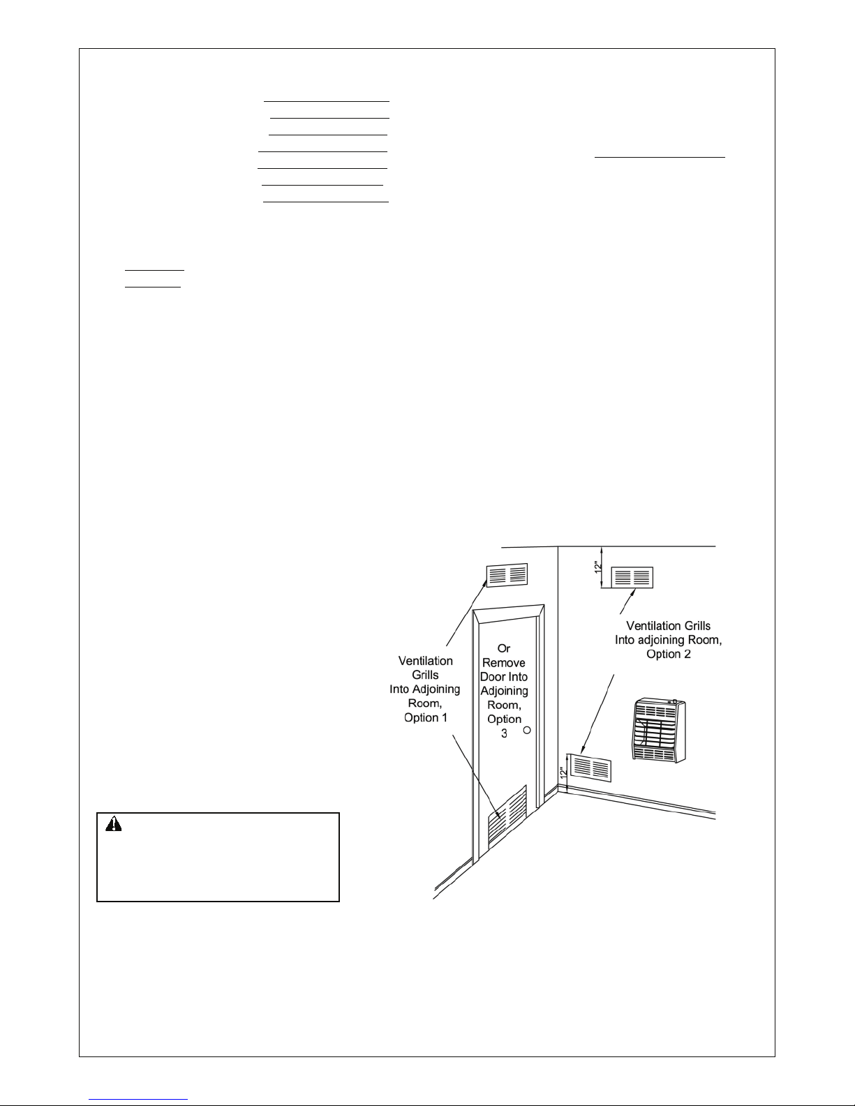
VENTILATION AIR
Ventilation Air From Inside Building
This fresh air would come from an adjoining
unconfined space. When ventilating to an
ad joining unconfin ed s pace, you must
provide two permanent openings: one within
12
" of the ceiling and one within 12" of the
floor on the wall connecting the two spaces
(see options 1 and 2, Figure 2). You can also
remove door into adjoining room (see option
3, Figure 2).
Follow the National Fuel Gas
Code NFPA 54/ANS Z223.1. Section 5.3, Air
for Combustion and Ventilation
for required
size of ventilation grills or ducts
If the actual Btu/Hr used is less than the maximum Btu/Hr the space can support, the space is an
unconfined space. You will need no additional fresh air ventilation.
Example:
Gas water heater 40,000 Btu/Hr
Vent free heater
+ 18,000 Btu/Hr
Total = 58,000 Btu/Hr
3. Add the Btu/Hr of all fuel burning appliances in the space.
Vent-free heater Btu/Hr
Gas water heater* Btu/Hr
Gas furnace Btu/Hr
Vented gas heater Btu/Hr
Gas Fireplace logs Btu/Hr
Other gas appliances* + Btu/Hr
Total = Btu/Hr
*Do not include direct-vent gas appliances. Direct-vent draws combustion air from the outdoors and
vents to the outdoors.
4. Compare the maximum Btu/Hr the space can support with the actual amount of Btu/Hr used.
Btu/Hr (maximum the space can support)
Btu/Hr (actual amount of Btu/Hr used)
Example
: 51,200 Btu/Hr(maximum the space can support)
58,000 Btu/Hr(actual amount of Btu/Hr used)
The space in the above example is a confined space because the actual Btu/Hr used is more than the
maximum Btu/Hr the space can support.
You must provide additional fresh air. Your options are as follows:
A. Rework worksheet, adding the space of an adjoining room. If the extra space provides an unconfined
space, remove door to adjoining room or add ventilation grills between rooms. See
Ventilation Air From
inside Building
, page 5.
B. Vent room directly to the outdoors. See
Ventilation Air From Outdoors
, page 6 .
C. Install a lower Btu/Hr heater, if lower Btu/Hr size makes room unconfined.
Figure 2 -Ventilation Air from Inside Building
6
VENTILATION AIR
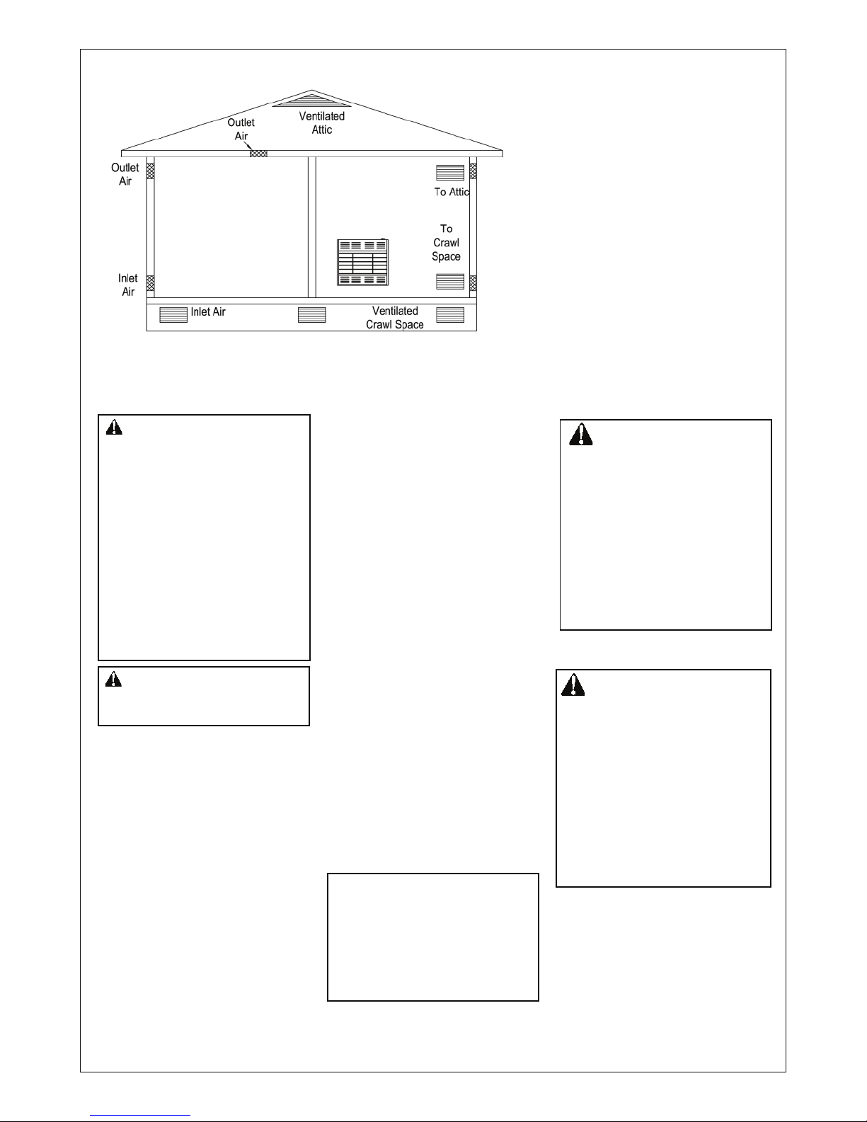
Ventilation Air From Outdoors
Provi de e xtr a fr esh air by u sin g
ventilation grills o r ducts: You mu st
provide two permanent openings: one
within 12
" of the ceiling and one within
12" of the floor.
Connect these items di rectly to the
outdoors or spaces open to the outdoors.
These spaces incl ude a ttics and crawl
spaces. Follow the
National Fuel Gas
Code NFPA 54/ANS Z223.1, Section 5.3.
Air for Combustion and Ventilation
for
required size of ventilation grills or ducts.
IMPORTANT: Do not provide openings
for inlet or outlet air into attic if attic has
a thermos ta t-controlled power vent.
Heated air entering the attic will activate
the power vent.
NOTICE: This heater is
intended for use as supplemental
heat. Use this heater along with
your primary heating system. Do
not install this heater as your
primary heat source. If you have
a central heating system, you
may run system’s circulating
blower while using heater. This
wi ll help c ir culate the heat
throughout the house. In the
event of a power outage, you can
use this heater as your primary
heat source.
CHECK GAS TYPE
Use only Propane/LP gas. If your
gas supply is not Propane/LP, do not
install heater. Call dealer where you
bought heater for proper type heater.
INSTALLATION NEEDS
Before installing heater, make sure
you have the items listed below.
!
piping (check local codes)
" sealant (resistant to Propane/LP gas)
" equipment shutoff valve*
" ground joint union
" test gauge connection*
" sediment trap
" tee joint
" pipe wrench
*A CSA/AGA design-certified equipment shutoff valve with 1/8" NPT
tap is an acceptable alternative to
test gauge connection. Purchase
the CSA/AGA design certified equip-
ment shutoff valve from your dealer.
LOCATING HEATER
This heater is designed to be
mounted on a wall. You can locate
heater on floor, away from a wall.
An optional floor mounting stand is
neede d. P urc has e the floo r
mounting stand from your dealer.
See Accessories, page 17.
For convenience and efficiency,
install heater
! where there is easy access for
operation, inspection, and service
! in coldest part of room
An optional fan kit is available from
your dealer. See Accessories,
page 17. If planning to use fan,
locate heater near an electrical
outlet.
INSTALLATION
CAUTION : If you in stall the
heater in a home garage
! heater pilot and burner must
be at least 18 inches above
floor.
! locate heater where moving
vehicle will not hit it.
CAUTION: This heater
cre ate s wa rm air cur ren ts.
The se curr ent s m ove h eat
to wa l l surf a c e s ne x t to
h e a te r . I n s ta l l ing h e at e r
ne xt to vinyl or cl ot h w all
c o ve r i n gs o r o p e ra t i n g
heater where impurities (such as
tobacco smoke, aromatic candles,
cleaning fluids, oil or kerosene
lamps, etc.) in the air exist may
discolor walls.
Figure 3 -Ventilation Air from Outdoors
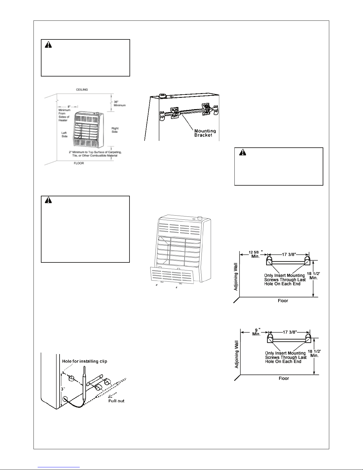
WA RNING : A qualified
service pers on must in stall
heater. Follow all local codes.
WARNING: Never install
the heater
! in a bedroom or bathroom.
! in a recreational vehicle.
! where curtains, furniture,
clothing, or other flammable
objects are less than 36 inches
from the front, top, or sides
of the heater.
! as a fireplace insert.
! in high traffic areas.
! in windy or drafty areas.
7
INSTALLATION
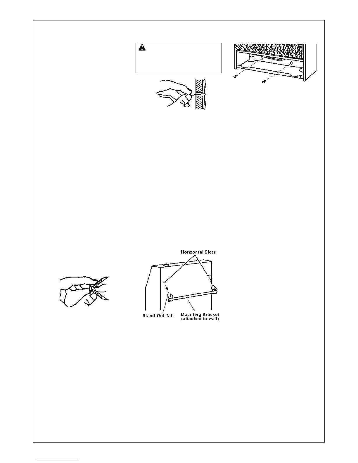
Figure 8 - Mounting Bracket
Clearances
Figure 7 - Removing Lower Front
Panel of Heater
Figure 4 -Mounting Clearances As
Viewed From Front Of Heater
Figure 5 - Moving Thermostat
Sensing Bulb
IMPORTAN T: Ve nt -free
heaters add moisture to the
air. Although this is beneficial,
ins t all i ng hea t er in roo m s
without enough ventilation air
may cause mildew to form
from too much moisture. See
Fresh Air for Combustion and
Ventilation
, pages 4 and 5.
FASTENING HEATER TO WALL
Mounting Bracket
The mounting bracket is located
on back p an el of heater (see
figure 6). It has been taped there
for sh ippi ng. Re m ove mo unti ng
bracket from back panel.
Removing Lower Front Panel Of
Heater.
1. Remove two screws near
bottom corners of front panel.
2. Pull bottom of lower front panel
forward, then down (see Figure
7).
Methods For Attaching Mounting
Bracket To Wall
Only use last hole on each end
of m ou nt in g bracket to att ac h
bracket to wall. These two holes
are 1 6 in ches ap art f rom their
c e n t e r s . A t ta c h m o un t i n g
bracket to wall only in one of two
ways:
1. Attaching to wall stud
2. Attaching to wall anchor
Attaching to Wall Stud: This
method p ro vides the strongest
hold. Insert mounting screws
th ro ugh m ounting bra ck et and
into wall studs.
Attaching to Wall Anchor: This
met hod allo ws you to att ach
mounting bracket to hollow walls
(wall areas between stu ds) or t o
solid walls (concrete or masonry).
Decide wh ich m et hod b et ter
suits your needs. Either method
will provide a secure hold for the
mounting bracket.
Marking Screw Locations
1. Tape mounting bracket to wall
wh ere h ea ter w il l b e lo cated.
Make sure mounting bracket is
level.
2. Mark s c rew l oca t ion s on
wall. (see Figure8)
Note:
Only mar k last hole on
each end of mounting bracket.
Insert mounting screws through
these holes only.
3. Remove tape and mounting
bracket from wall.
WARNING: Maintain
minimum clearances shown in
Figure 4. If you can, provide greater
c l e a r a nce s f r o m f l o or
and joining wall.
Figure 6 -Mounting Bracket
Location
INSTALLING THERMOSTAT
SENSING BULB
For T-Stat Models Only
1. Pull out the sensing bulb from the
two clips located in the shippng
position according to the direction
as shown by the arrow. There is no
need to take out the two bulb clips.
2. Take out the bulb clip from the
hardware package and insert it into
the square hole and then insert the
sensing bulb into the bulb clip (see
Figure 5).
WARNING: Maintain the
min imum clea ran ces s how n
i n F i g u r e 4 . I f y o u c a n ,
provide greater clearances from
floor, ceiling, and joining wall.
M o d e l H R 2 5 M L H R 2 5 T L
M o d e l H R 15M L H R 1 5 TL
8
INSTALLATION
Figure 11 - Mounting Heater Onto
Mounting Bracket
Figure 9 - Folding Anchor
Figure 10 - Popping Open Anchor
Wing For Thin Walls
Attaching Mounting Bracket to
Wall
Note: Wall anchors, mounting
screws, and spacers are in
hardware package. The hardware
package is provided with heater.
Attaching to Wal l Stud Method
For attaching mounting bracket to
wall studs
1. Drill holes at marked locations
using 9/64" drill bit.
2. Place mounting bracket onto
wall. Line up last hole on each
end of bracket with holes drilled
in wall.
3. Insert mounting screws through
bracket and into wall studs.
4. Tighten screws until mounting
bracket is firmly fastened to
wall studs.
Attaching to Wall Anchor
Method
For attaching mounting bracket to
hollow walls (wall areas between
studs) or solid walls (concrete or
masonry)
1. Drill holes at marked locations
using 5/16" drill bit. For solid
walls (concrete or masonry), drill
at least 1" deep.
2. Fold wall anchor as shown in
Figure 9 below.
3. Insert wall anchor (wings
first) into hole. Tap anchor
flush to wall.
4. For thin walls (1/2
" or less),
insert red key into wall
anchor. Push red key to
"pop" open anchor wings
(see Figure 10).
IMPOR TANT: Do not
hammer key! For thick walls
(over 1/2" thick) or solid walls,
do not pop open wings.
5. Place mounting bracket onto
wall. Line up last hole on
each end of bracket with wall
anchors.
6. Insert mounting screws through
bracket and into wall anchors.
7. Tighten screws until mounting
bracket is firmly fastened to wall.
Pl ac ing H ea ter o n Mounting
Bracket
1. Locate two horizontal slots on
ba ck pane l o f heater (see
Figure 11).
2. Place heater onto mounting
bracket. Slide horizontal slots
onto s ta nd -o ut tabs on
mounting bracket.
Ins tall ing Bo tto m Moun t ing
Screws
1. Locate two bottom mounting
holes. These holes are near
bottom on back panel of
heater(see Figure 12).
2. Mark screw locations on wall.
3. Remove heater from mounting
bracket.
4. If installing bottom mounting
screws into hollow or solid wall,
install wall anchors.Follow steps
1 through 4 under Attaching
To Wall Anchor Method. If
installing bottom mounting
screw
into wall stud, drill holes at
marked locations using 9/64
"
drill bit.
5. Replace heater onto mounting
bracket.
6. Place spacers between bottom
mounting holes and wall anchor
or drilled holes.
7. Hold spacer in place with one
hand. With other hand, insert
mounting screw through
bottom mounting hole and
spacer. Place tip of screw in
opening of wall anchor or drilled
holes .
8. Tighten both screws until heater
is firmly secured to wall. Do not
over tighten.
! Note: Do not replace lower front
panel at this time. Replace lower
front panel after making gas
connections and checking for
leaks (see pages 9 and 10).
Figure 12 - Installing Bottom
Mounting Screws
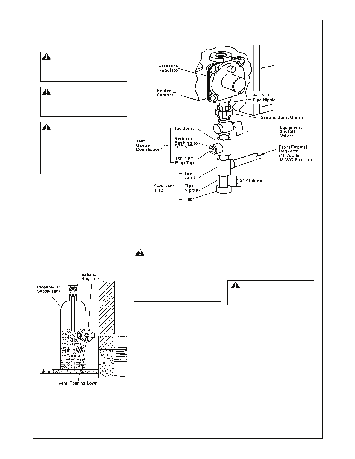
CONNECTING TO GAS SUPPLY
WA RN ING: A qua li fied
servi ce person must connect
heater to gas supply. Follow all
local codes.
WARNING: This appliance
requires a 3/8" NPT (National
Pipe Thread) inlet connection
to the pressure regulator.
CAUTION: Never connect
h e a t e r d i rec t l y t o t he
propane/LP supply. This heater
requires an external regulator
(not supp l i e d ) . Instal l the
external regulator between the
heater and propane/LP supply.
*A CSA/AGA design-certified equipment shutoff valve with 1/8
" NPT tap is
an acceptable alternative to test gauge connection. Purchase the CSA/AGA
design-certified equipment shutoff valve from your dealer.
IMPORTANT: Install an equipment
shutoff v al ve in an access ible
location. The equ ipment shut off
valve is for turning on or shutting
off the gas to the appliance.
Install sediment trap in supply line
as shown in Figure 14. L ocate
sediment trap where it is within
reac h for c lean i n g. Lo c ate
sediment trap where trapped
matter is not likely to freeze. A
sediment trap traps moisture and
contaminants. This keeps them
from going into heater controls. If
sediment trap is not installed or is
ins t alle d wr ong , he ater ma y
not run properly.
IM PORTANT
: Hold pr es sure
regu l ator wit h wre n ch when
conne cting it to gas piping and/or
fittings.
CAUTION: Use pipe joint
se alant that is resis ta nt to
liquid petroleum (LP) gas.
Figure 14 -Gas Connection
The installer must supply an
external regulato r. The extern al
regulator will reduce incoming gas
p r e s s u r e . Yo u m u s t r e d u c e
incoming gas pressure to between
11 and 13 inches of water. If you
do n ot redu ce inco min g gas
pressure, heater regulator damage
could occur . I n s tall ext e r n a l
regulator with the vent pointing
down as shown in Fi gure 13.
Pointing the vent down protects it
from freezing rain or sleet.
Figure 13 - External Regulator with
Vent Pointing Down
CAUTION: Use only new, black
iron or steel pipe. Internally-tinned
copper tubing may be used in
certain areas. Check your local
codes. Use pipe of large enough
diameter to allow proper gas volume
to heater. If pipe is too small,
undue loss of pressure will occur.
Insta llati on mu st includ e an
equipment shutoff valve, union,
and plugged 1/8
" NPT tap. Locate
NPT tap within reach for test gauge
ho ok up . NPT t ap must b e
upstream from heater(see Figure 14).
Apply pipe joint sealant lightly to
male threads. This will prevent
excess seal ant from going into
pipe. Excess sealant in pipe could
result in clogged heater valves.
r
Typical Inlet Pipe Diameters
All models up to 20,000 BTU’s use
3/8’’ or greater pipe;
All models 25,000 BTU’s and higher,
use 1/2” or greater pipe.
INSTALLATION
9
 Loading...