

HearthRite HR06MN-1, HR10MN-1, HR10TN-1 Owner's Operation And Installation Manual
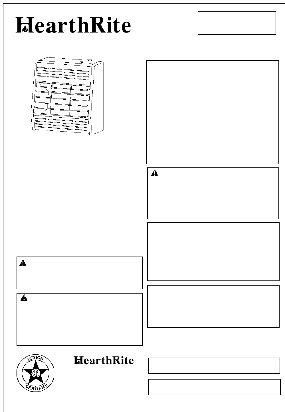
INFRARED VENT-FREE
NATURAL GAS
SPACE HEATER
OWNER’S OPERATION AND INSTALLATION MANUAL
Do not store, or use gasoline or other flammable
vapors and liquids in the vicinity of this or any
other appliance.
WHAT TO DO IF YOU SMELL GAS
Do not try to light any appliance.
Do not touch any electrical switch; do not
use any phone in your building.
Immediately call your gas supplier from a
neighbor’s phone. Follow the gas supplier’s
instructions.
If you cannot reach your gas supplier, call
HR06MN-1 HR10MN-1 HR10TN-1
Table of Contents
Important Safety Information.................................2
Product Features.....................................................3
Proper V entilation & Fresh Air ..............................4
Installation................................................................6
Operating Y our Heater ............................................10
Cleaning & Maintenance.......................................13
Trouble Shooting...................................................14
Specifications..........................................................17
Parts List..................................................................19
W arranty Information...........................................24
WARNING: If the information in this
manual is not followed exactly, a fire or
explosion may result causing property
damage, personal injury, or loss of life.
WARNING: This is an unvented gasfired heater. It uses air (oxygen) from the
room in which it is installed. Provisions for adequate combustion and ventilation air must be provided. Refer to Air
F or Combustion and Ventilation section on
page 4 of this manual.
the fire department.
Installation and service must be performed by a
qualified installer, service agency or gas
supplier.
WARNING: Improper installation,
adjustment, alteration, service or maintenance can cause injury or property damage.
Refer to this manual for correct installation and
operational procedures. For assistance or
additional information consult a qualified
installer, service agency, or gas supplier.
This appliance may be installed in an aftermarket* permanently located, manufactured
(mobile) home, where not prohibited by local
codes.
This appliance is only for use with the type of
gas indicated on the rating plate. This
appliance is not convertible for use with other
gases.
WA TER V APOR: A BY -PRODUCT OF UNVENTED ROOM
HEA TERS
Water vapor is a by-product of gas combustion.An
unvented room heater productes approximately one (1)
ounce (30ml) of water for every 1,000 BTU’s (.3KW’s) of
gas input per hour. Refer to page 3.
*Aftermarket: Completion of sale, not for purpose of
resale, from the manufacturer.
A Division of Empire Comfort Systems,Inc.
918 Freeburg Avenue
Belleville,IL 62220
Phone : 618-233-7420 or 1-800-851-3153
Fax : 618-233-7097 or 1-800-443-8648
www.hearthrite.com
Installer: Please leave these instructions with the
consumer.
Consumer: Please retain these instructions for
future use.
IMPORTANT
SAFETY INFORMATION
WARNINGS
IMPORTANT: Read this
owner’s manual carefully and
completely before trying to
assemble, operate, or service
this heater. Improper use of
this heater can cause serious
injury or death from burns,
fire, explosion, electrical
shock, and carbon monoxide
poisoning.
WARNING: Do not use any
accessory not approved for
use with this heater.
WARNING: Any change to
this heater or its controls can
be dangerous.
Do not place clothing or other
flammable material on or near
the appliance. Never place any
objects on the heater.
Due to high temperatures, heater
should be kept out of
traffic and away from furniture
and draperies.
Surface of heater becomes
very hot when running heater.
Keep children and adults away
from hot surface to avoid burns
or clothing ignition. Heater will
remain hot for a time after shut
down. Allow surface to cool
before touching.
Carefully supervise young
children when they are in the
same room with heater.
Make sure grill guard is in
place before running heater.
Keep the appliance area clear
and free from combustible
materials, gasoline, and other
flammable vapors and liquids.
1. This appliance is only for use
with the type of gas indicated
on the rating plate. This
appliance is not convertible for
use with other gases.
2. If you smell gas
Shut off gas supply.
Do not try to light any appliance.
Do not touch any electrical switch,
do not use any phone in your
building.
Immediately call your gas sup plier from a neighbor’s phone.
Follow the gas supplier’s
instructions.
If you cannot reach your gas
supplier, call the fire
department.
3. Do not install models HR10MN
and HR10TN in a bathroom.
4. This heater needs fresh,
outside air ventilation to run
properly. This heater has an
Oxygen Depletion Sensor
(ODS) safety shutoff system.
The ODS shuts down the
heater if not enough fresh air
is available. See
Fresh Air For
Combustion And Ventilation
pages 4 through 6
5. Keep all air openings in the
front and bottom of heater
clear and free of debris. This
will insure enough air for
proper combustion
6. If heater shuts off. Do not
relight until you provide fresh,
outside air. If heater keeps
shutting off, have it serviced.
7. Do not operate heater
where flammable liquids or
vapors are used or stored
under dusty conditions
8. Turn heater off before using
furniture polish, wax, carpet
cleaner, or similar products. If
heated, the vapors from these
products may create a white
powder residue within burner
box or on adjacent walls or
furniture.
9. Always run heater with control
knob at ON, LOW or HIGH
locked positions. Never set
control knob between locked
positions. Poor combustion
and higher levels of carbon
monoxide may result.
10. Do not use heater if any part
has been under water.
Immediately call a qualified
service technician to inspect
the room heater and to
replace any part of the control
system and any gas control
which has been under water
11. Turn off heater and let cool
before servicing. Only a qualified
service person should service
and repair heater.
12. Operating heater above
elevations of 4,500 feet could
cause pilot outage.
DANGER: Carbon monoxide
poisoning may lead to death!
Carbon Monoxide Poisoning.
Early signs of carbon monoxide
poisoning resemble the flu with
headaches, dizziness, or nausea
If you have these signs, the heater
may not be working properly. Get
fresh air at once! Have heater
serviced. Some people are more
affected by carbon monoxide than
others. These include pregnant
women, persons with heart or lung
disease or anemia, those under the
influence of alcohol, and those
at high altitudes.
Natural Gas: Natural gas is
odorless. An odor-making agent is
added to natural gas. The odor
helps you detect a natural gas leak .
However, the odor added to natural
gas can fade. natural gas may be
present even though no odor exists.
Make certain you read and understand all warnings. Keep
this manual for reference. It is your
guide to safe and proper operation
of this heater.
2
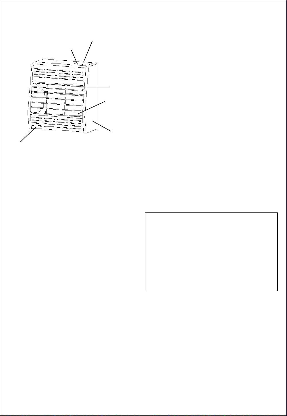
Ignitor
Button
PRODUCT FEATURES
Control
Knob
Grill
Burners
LOCAL CODES
Install and use heater with care. Follow all local
codes. In the absence of local codes, use the
latest edition of
also known as NFPA 54*.
*Available from :
American National Standards Institute, Inc.
National Fuel Gas Code ANSZ223.1
1430 Broadway
New York, NY 10018
National Fire Protection Association, Inc.
Batterymarch Park
Quincy, MA 02269
,
Lower
Front
Panel
Heater
Cabinet
Figure1-Vent-Free Natural Gas Heater
SAFETY DEVICE
A standard requirement for all vent-free room
heaters. This heater has a pilot with an Oxygen
Depletion Sensor(ODS) safety shutoff system.
The ODS/pilot shuts off the heater if there is
not enough fresh air.
PIEZO IGNITION SYSTEM
This heater is equipped with a piezo ignitor.
This system requires no matches, batteries, or
other sources to light heater.
THERMOSTATIC HEAT
CONTROL ON THERMOSTAT
MODELS
These heaters have a control valve with a
thermostat sensing bulb. This results in the
greatest heater comfort and may result in
lower gas bills.
WATER VAPOR: A BY-PRODUCT OF UNVENTED ROOM HEATERS
Water vapor is a by-product of gas combustion.An
unvented room heater productes approximately one (1)
ounce (30ml) of water for every 1,000 BTU’s (.3KW’s) of
gas input per hour.
Unvented room heaters are recommended as
supplemental heat (a room) rather than a primary heat
source (an entire house) .In most supplemental heat
application, the water vapor does not create a problem.
In most applications, the water vapor enhances the low
humidity atmosphere experienced during cold weather.
QUALIFIED INSTALLING AGENCY
Installation and replacement of gas piping, gas
utillzation equipment or accessories and repair and
servicing of equipment shall be performed only by a
qualified agency. The term “qualified agency” means
any individual, firm , corporation, or company that
either in person or through a representative is
engaged in and is responsible for (a) the installation,
testing , or replacement of gas piping or (b) the
connection , installation , testing , repair , or servicing
of equipment ; that is experienced in such work; that
is familiar with all precautions required , and that has
complied with all the requirements of the authority
having jurisdiction.
State of Massachsetts: The installation must be
made by a licensed plumber or gas fitter in the
Commonwealth of Massachusetts .
Sellers of unvented propane or natural gas-fired
supplemental room heaters shall provide to each
purchaser a copy of 527 CMR 30 upon sale of the
unit.
In the state of Massachusetts, unvented propane or
nature gas-fired space heaters shall be prohibited in
bedrooms and bathrooms.
UNP ACKING
1. Remove heater from carton.
2. Remove all protective packaging applied to
heater for shipment.
3. Check heater for any shipping damage. If heater
is damaged, promptly inform dealer where you
bought heater.
The following steps will help insure that water vapor
does not become a problem.
1. Be sure the heater is sized properly for the
application, including ample combustion air and
circulation air.
2. If high humidity is experienced, a dehumidifier may
be used to help lower the water vapor content of the
air.
3. Do not use an unvented room heater as the primary
heat source.
3
FRESH AIR FOR
COMBUSTION AND
VENTILATION
WARNING: This heater
shall not be installed in a
confined space or unusually
tight construction unless
provisions are provided for
adequate combustion and
ventilation air. Read the
following instructions to
insure proper fresh air for this
and other fuel-burning
appliances in your home.
PROVIDING ADEQUATE
VENTILATION
The following are excerpts from
National Fuel Gas Code. NFPA
54/ANS Z223.1, Section 5.3.
Combustion and Ventilation. All
spaces in homes fall into one of
the three following ventilation
classifications:
1. Unusually Tight Construction
2. Unconfined Space
3. Confined Space
The information on pages 4
through 6 will help you classify
your space and provide adequate
ventilation.
Air for
Unusually Tight Construction
The air that leaks around doors and
windows may provide enough fresh
air for combustion and ventilation.
However, in buildings of unusually
tight construction, you must provide
additional fresh air.
Unusually tight construction is
defined as construction where:
a. walls and ceilings exposed to the
outside atmosphere have a
continuous water vapor retarder
with a rating of one perm (6
per pa-sec-m
openings gasketed or sealed
b. weather stripping has been
added on openable windows and
doors
and
c. caulking or sealants are applied
to areas such as joints around
window and door frames, between
sole plates and floors, between
wall-ceiling joints, between wall
panels, at penetrations for plumbing,
electrical, and gas lines, and at
other openings. If your home meets
all of the three criteria above, you
must provide additional fresh air.
2
) or less with
See Ventilation Air From Outdoors,
pages 5 and 6.
not meet all of the three criteria
above, see
If your home does
Determining Fresh-Air
Flow for Heater Location, page 4, 5
-11
10
kg
×
and
Confined and
Unconfined Space
The National Fuel Gas Code
ANS Z223.1
space as a space whose volume
is less than 50 cubic feet per
1,000 Btu per hour (4.8 m
of the aggregate input rating of all
appliances installed in that space
and an unconfined space as a
space whose volume is not less
than 50 cubic feet per 1,000 Btu
per hour (4.8 m
aggregate input rating of all
appliances installed in that space.
Rooms communicating directly
with the space in which the
appliances are installed*, through
openings not furnished with
doors, are considered a part of
the unconfined space.
This heater shall not be installed
in a confined space or unusually
tight construction unless
provisions are provided for
adequate combustion and
ventilation air.
Adjoining rooms are
*
communicating only if there are
doorless passageways or
ventilation grills between them.
defines a confined
3
per kw)
3
per kw) of the
DETERMINING FRESH-AIR FLOW FOR HEATER LOCATION
Determining if you Have a Confined or Unconfined Space*
Use this worksheet to determine if you have a confined or unconfined space.
Space: Includes the room in which you will install heater plus any adjoining rooms with doorless passageways
or ventilation grills between the rooms.
1. Determine the volume of the space (length
Length
Example: Space size18ft.(length)
If additional ventilation to adjoining room is supplied with grills or openings, add the volume of these
rooms to the total volume of the space.
2. Divide the space volume by 50 cubic feet to determine the maximum Btu/Hr the space can support.
(volume of space) 50 cu. ft.=(Maximum Btu/Hr the space can support)
Example: 2304 cu. ft. (volume of space)
WARNING: If the area in which the heater may be operated is smaller than that defined as an
unconfined space or if the building is of unusually tight construction, provide adequate combustion and
ventilation air by one of the methods described in the National Fuel Gas Code, ANS Z223.1, Section 5.3
or applicable local codes.
Width×Height= cu.ft. (volume of space)
×
16ft.( width)×8ft. (ceiling height)=23040cu. ft. (volume of space)
×
50 cu.ft.=46.1 or 46.100(maximum Btu/Hr the space can support)
width×height).
×
4
3. Add the Btu/Hr of all fuel burning appliances in the space.
Vent-free heater
Gas water heater*
Gas furnace
Vented gas heater
Gas Fireplace logs
Other gas appliances* +
Total =
*Do not include direct-vent gas appliances. Direct-vent draws combustion air from the outdoors and
vents to the outdoors.
4. Compare the maximum Btu/Hr the space can support with the actual amount of Btu/Hr used.
Btu/Hr (maximum the space can support)
Btu/Hr (actual amount of Btu/Hr used)
Example
50,000 Btu/Hr(actual amount of Btu/Hr used)
The space in the above example is a confined space because the actual Btu/Hr used is more than the
maximum Btu/Hr the space can support.
You must provide additional fresh air. Your options are as follows:
A. Rework worksheet, adding the space of an adjoining room. If the extra space provides an unconfined
space, remove door to adjoining room or add ventilation grills between rooms.
Inside Building
B. Vent room directly to the outdoors. See
C. Install a lower Btu/Hr heater, if lower Btu/Hr size makes room unconfined.
If the actual Btu/Hr used is less than the maximum Btu/Hr the space can support, the space is an
unconfined space. Y ou will need no additional fresh air ventilation.
: 46,100 Btu/Hr(maximum the space can support)
, page 5.
Btu/Hr
Btu/Hr
Btu/Hr
Btu/Hr
Btu/Hr
Btu/Hr
Btu/Hr
Ventilation Air From Outdoors
Example:
Gas water heater 40,000 Btu/Hr
Vent free heater
total = 50,000 Btu/Hr
+ 10,000 Btu/Hr
See Ventilation Air From
, page 6 .
AIR FOR COMBUSTION AND
VENTILATION
Continued
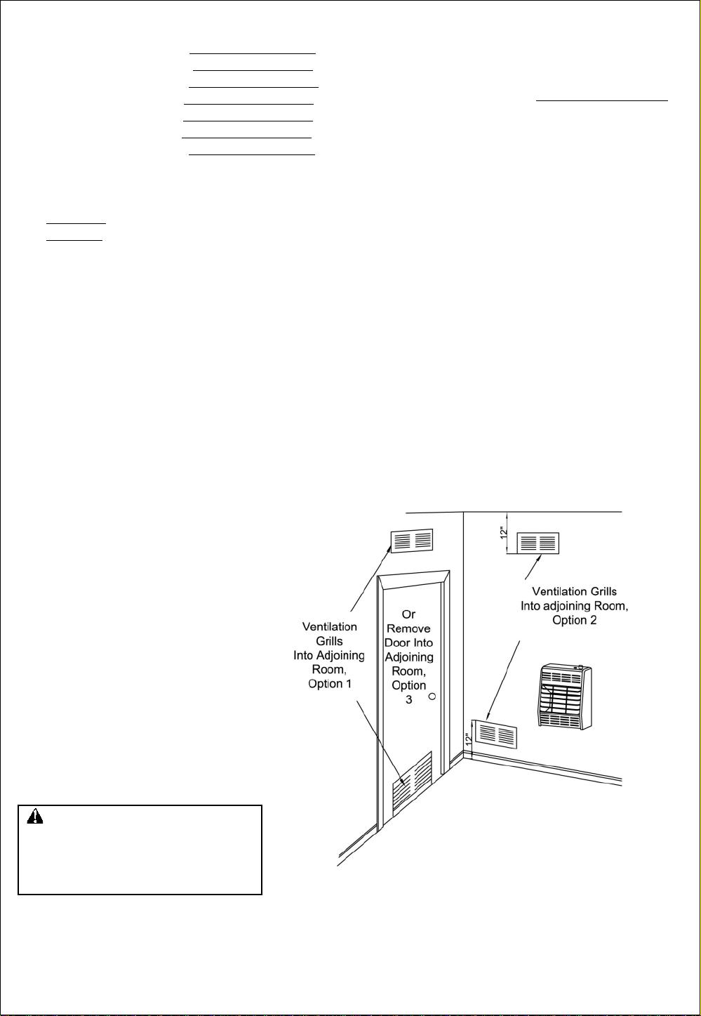
VENTILATION AIR
Ventilation Air From Inside Building
This fresh air would come from an
adjoining unconfined space. When
ventilating to an adjoining unconfined
space, you must provide two permanent
openings: one within 12
and one within 12
wall connecting the two spaces (see
options 1 and 2, Figure 2). You can also
remove door into adjoining room (see
option 3, Figure 2).
Fuel Gas Code NFPA 54/ANS Z223.1.
Section 5.3, Air for Combustion and
Ventilation
ventilation grills or ducts
WARNING: Rework worksheet, add-
ing the space of the adjoining
unconfined space. The combined spaces
must have enough fresh air to supply all
appliances in both spaces.
for required size of
" of the ceiling
" of the floor on the
Follow the National
Figure 2 -Ventilation Air from Inside Building
5
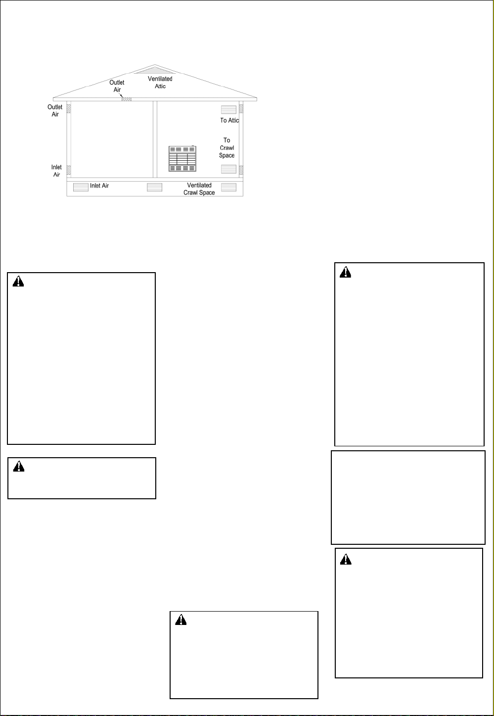
VENTILATION AIR
Figure 3 -Ventilation Air from Outdoors
Ventilation Air From Outdoors
Provide extra fresh air by using
ventilation grills or ducts: You must
provide two permanent openings: one
within 12
12
Connect these items directly to the
outdoors or spaces open to the outdoors.
These spaces include attics and crawl
spaces. Follow the
" of the ceiling and one within
" of the floor.
National Fuel Gas
Code NFPA 54/ANS Z223.1, Section 5.3.
Air for Combustion and Ventilation
required size of ventilation grills or ducts.
IMPORTANT: Do not provide openings
for inlet or outlet air into attic if attic has
a thermostat-controlled power vent.
Heated air entering the attic will activate
the power vent.
for
INSTALLATION
NOTICE: This heater is
intended for use as supplemental
heat. Use this heater along with
your primary heating system. Do
not install this heater as your
primary heat source. If you have
a central heating system, you
may run system’s circulating
blower while using heater. This
will help circulate the heat
throughout the house. In the
event of a power outage, you can
use this heater as your primary
heat source.
WARNING: A qualified
service person must install
heater. Follow all local codes.
CHECK GAS TYPE
Use only natural gas. If your
gas supply is not natural, do
not install heater. Call dealer
where you bought heater for
proper type heater.
INSTALLATION NEEDS
Before installing heater, make sure
you have the items listed below.
piping (check local codes)
sealant (resistant to natural
gas)
equipment shutoff valve*
ground joint union
test gauge connection*
sediment trap
tee joint
pipe wrench
*A CSA/AGA design-certified equipment shutoff valve with 1/8
tap is an acceptable alternative to
test gauge connection. Purchase
the CSA/AGA design certified
equipment shutoff valve from your
dealer.
" NPT
LOCATING HEATER
This heater is designed to be
mounted on a wall.
For convenience and efficiency,
install heater
where there is easy access for
operation, inspection, and service.
in coldest part of room.
CAUTION: If you install the
heater in a home garage
heater pilot and burner must
be at least 18 inches above
floor.
locate heater where moving
vehicle will not hit it.
6
WARNING: Never install
the heater
in a bathroom(Models
HR10MN and HR10TN , only
HR06MN is allowed in a
bathroom. Check local codes.)
in a recreational vehicle.
where curtains, furniture,
clothing, or other flammable
objects are less than 36 inches
from the front, top, or sides
of the heater.
as a fireplace insert.
in high traffic areas.
in windy or drafty areas.
When the HR06MN is installed in
bathrooms,do not use flammable
products such as aerosol hair spray,
foot spary or any product that contains
flammable vapors and keep towels
away from heater.(only HR06MN is
allowed in a bathroom.)
CAUTION: This heater creates
warm air currents. These currents
move heat to wall surfaces next
to heater. Installing heater
next to vinyl or cloth wall coverings
or operating heater where impurities
(such as tobacco smoke, aromatic
candles, cleaning fluids, oil or kerosene lamps, etc.) in the air exist
may discolor walls.
INSTALLATION
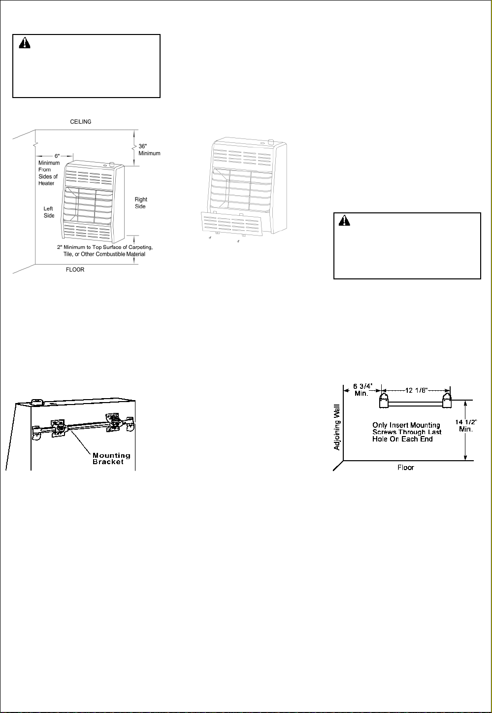
WARNING: Maintain the
minimum clearances shown
in Figure 4. If you can,
provide greater clearances from
floor, ceiling, and joining wall.
Figure 4 -Mounting Clearances As
Viewed From Front Of Heater
FASTENING HEATER TO WALL
Mounting Bracket
The mounting bracket is located
on back panel of heater (see
Figure 5). It has been taped there
for shipping. Remove mounting
bracket from back panel.
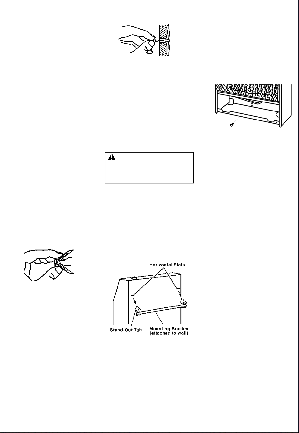
Removing Lower Front Panel Of
Heater
1. Remove two screws near
bottom corners of lower front
panel.
2. Pull bottom of lower front panel
forward, then down (see Figure
6).
Figure 6 - Removing Lower Front
Panel Of Heater
Methods For Attaching Mounting
Bracket To Wall
Only use last hole on each end
of mounting bracket to attach
bracket to wall. Attach mounting
bracket to wall only in one of two ways:
1. Attaching to wall stud
2. Attaching to wall anchor
Attaching to Wall Stud: This method
provides the strongest hold. Insert
mounting screws through mounting
bracket and into wall studs.
Attaching to Wall Anchor: This
method allows you to attach
mounting bracket to hollow walls
(wall areas between studs) or to
solid walls (concrete or masonry).
Decide which method better
suits your needs. Either method
will provide a secure hold for the
mounting bracket.
Marking Screw Locations
1. Tape mounting bracket to wall
where heater will be located.
Make sure mounting bracket is
level.
WARNING: Maintain
minimum clearances shown in
Figure 4. If you can, provide
greater clearances from floor
and joining wall.
2. Mark screw locations on
wall. (see Figure 7)
Note:
Only mark last hole on
each end of mounting bracket.
Insert mounting screws through
these holes only.
3. Remove tape and mounting
bracket from wall.
Figure 5 -Mounting Bracket
Location
Figure 7 - Mounting Bracket
Clearances
7
INSTALLATION
Attaching Mounting Bracket T o
Wall
Note:
Wall anchors, mounting
screws, and spacers are in
hardware package. The hardware
package is provided with heater.
Attaching to Wall Stud Method
For attaching mounting bracket to
wall studs
1. Drill holes at marked locations
using 9/64
2. Place mounting bracket onto
wall. Line up last hole on each
end of bracket with holes drilled
in wall.
3. Insert mounting screws through
bracket and into wall studs.
4. Tighten screws until mounting
bracket is firmly fastened to
wall studs.
Attaching to Wall Anchor Method
For attaching mounting bracket to
hollow walls (wall areas between
studs) or solid walls (concrete or
masonry)
1. Drill holes at marked locations
using 5/16
walls (concrete or
drill at least 1
2. Fold wall anchor as shown in
Figure 8 below.
Figure 8 - Folding Anchor
3. Insert wall anchor (wings
first) into hole. Tap anchor
flush to wall.
4. For thin walls (1/2
insert red key into wall
anchor. Push red key to
"pop" open anchor wings.
(see Figure 9).
" drill bit.
" drill bit. For solid
masonry),
" deep.
" or less),
Figure 9 - Popping Open Anchor
Wing For Thin Walls
5. Place mounting bracket onto
wall. Line up last hole on
each end of bracket with wall
anchors.
6. Insert mounting screws through
bracket and into wall anchors.
7. Tighten screws until mounting
bracket is firmly fastened to
wall.
IMPORTANT: Do not
hammer key! For thick walls
(over 1/2
do not pop open wings.
Placing Heater on Mounting
Bracket
1. Locate two horizontal slots on
back panel of heater (see
Figure 10).
2. Place heater onto mounting
bracket. Slide horizontal slots
onto stand-out tabs on
mounting bracket.
Figure 10 - Mounting Heater Onto
Mounting Bracket
" thick) or solid walls,
Installing Bottom Mounting
Screws
1. Locate bottom mounting hole. This
hole is near bottom on back
panel of heater (see Figure 11).
2. Mark screw locations on wall.
3. Remove heater from mounting
bracket.
Figure 11 - Installing Bottom
Mouting Screw
4. If installing bottom mounting
screw into hollow or solid wall,
install wall anchors. Follow
steps 1 through 4 under
ing to Wall Anchor Method
installing bottom mounting screw
into wall stud, drill holes at
marked locations using 9/64
drill bit.
5. Replace heater onto mounting
bracket.
6. Place spacers between bottom
mounting holes and wall anchor
or drilled hole.
7. Hold spacer in place with one
hand. With other hand, insert
mounting screw through bottom
mounting hole and spacer. Place
tip of screw in opening of wall
anchor or drilled hole.
8. Tighten screw until heater is firmly
secured to wall. Do not over
tighten.
Note: Do not replace lower front
panel at this time. Replace lower
front panel after making gas
connections and checking for
leaks (see page 9).
Attach
. If
"
8
 Loading...