


Hearth Home RCT-MLT-II Operating Instructions
RCT-MLT-II Remote Control Kits
- Installation and Operating Instructions -
INTRODUCTION
The remote control system can be operated thermostatically or manually from the transmitter. The system operates on radio frequencies (RF) within a 20 foot range. Can
be used with DSI, IPI or Standing Pilot systems.
This remote control kit has a hand held transmitter that
can be used as a remote on/o or as a thermostat. The
transmitter display shows the current room temperature,
target temperature, timer setting, on/o status, low battery indicator, current time, burner/valve operation and
fan operation. Electrical ratings for the receiver are: 110
VAC, 60 Hz, 6 W.
If pertinent, see additional replace wiring diagrams on
pages 9 to 11.
INSTALLATION PRECAUTIONS
This remote control kit is tested and safe when installed
in accordance with this installation manual.
Installation of this kit MUST be done by a qualied
service technician.
NOTE: A manometer MUST be used to set the
manifold pressure on the gas valve.
It is the responsibility of the installer to read all instructions before starting installation and to follow these
instructions carefully during installation. Modication of
the remote control system or any of its components will
void the warranty and may cause a re hazard.
NOTE: The factory installed junction box in the gas
replace must be wired with 110 VAC before installing this kit. See Installation Instructions section.
CAUTION: All wiring should be done by a qualied
electrician and shall be in compliance with local codes
and with the National Electric Code ANSI/NFPA No. 70current (in the United States), or with the current CSA
C22.1 Canadian Electric Code (in Canada).
WARNING: DO NOT CONNECT 110-120 VAC
WIRING TO THE GAS CONTROL VALVE OF THIS
APPLIANCE.
FCC REQUIREMENTS
WARNING: CHANGES OR MODIFICATIONS TO
THIS UNIT NOT EXPRESSLY APPROVED BY
THE PARTY RESPONSIBLE FOR COMPLIANCE
COULD VOID THE USER’S AUTHORITY TO OPERATE THE EQUIPMENT.
NOTE: This equipment has been tested and found
to comply with the limits for a Class B digital device,
pursuant to Part 15 of the FCC Rules. These limits are
designed to provide reasonable protection against harmful interference in a residential installation. This equipment generates, uses, and can radiate radio frequency
energy and, if not installed and used in accordance with
the instructions, may cause harmful interference to radio
communications. However, there is no guarantee that
interference will not occur in a particular installation. If
this equipment does cause harmful interference to radio
or television reception, which can be determined by turn-
ing the equipment o and on, the user is encouraged
to try to correct the interference by one or more of the
following measures:
- Reorient or relocate the receiving antenna.
- Increase the separation between the equipment and
receiver.
- Connect the equipment into an outlet on a circuit different from that to which the receiver is connected.
- Consult the dealer or an experienced radio TV technician for help.
Canadian Equipment Requirements
This digital apparatus does not exceed the (Class A/Class
B)* limits for radio noise emissions from digital apparatus set out in the Radio Interference Regulations of the
Canadian Department of Communications. Le present
appareil numerique n’emet pas de bruits radioelectriques
depassant les limites applicables aux appareils numeriques (de la class A/de la class B)* prescrites dans le
Reglement sur le brouillage radioelectrique edicte par le
ministere des Communications du Canada.
This device complies with RSS-210 of Industry and Science Canada. Operation is subject to the following two
conditions: (1) this device may not cause interference,
and (2) this device must accept any interference, including interference that may cause undesired operation of
the device.
Hearth & Home Technologies • RCT-MLT-HHT Remote Control Instructions • 100-907 Rev. N • 10/20
1
INSTALLATION INSTRUCTIONS
ACCESS HOLE
COVER
PLATE
110 VAC
SERVICE
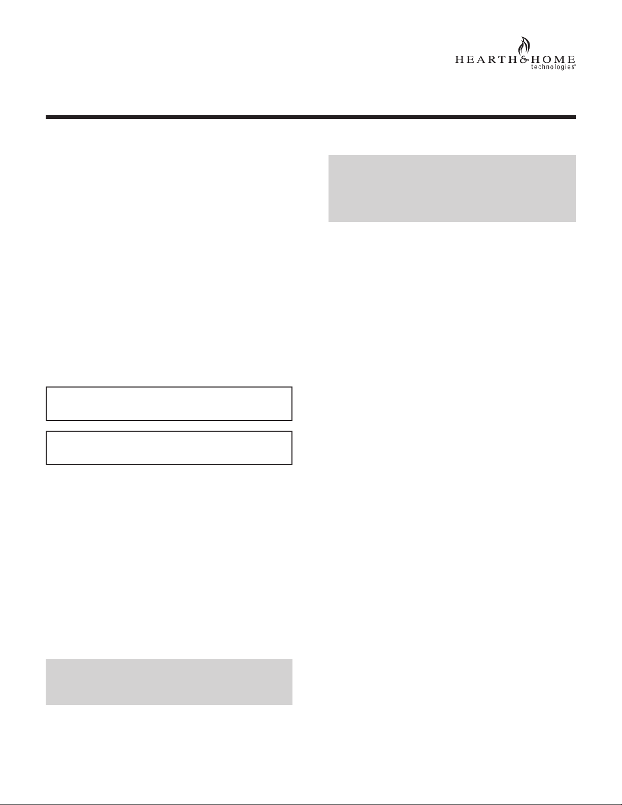
Installing Electrical Service to the Junction Box
WARNING: TURN ELECTRICAL POWER OFF AT
THE CIRCUIT BREAKER BEFORE BEGINNING
THIS INSTALLATION.
Wire Colors
• Gas Valve - Millivolt or
Electronic Ignition .............................................. Red
• Fan/Blower - 110 VAC .........................Plug from Fan
• Flame Controller - HI/LO solenoid ..................Orange
NOTE: Some appliances do not have a cover plate. Instead, there is a hole through which the Romex clamp is
attached to the outer wrap.
1. Remove the electrical cover plate from the lower side
of the replace. Remove the knock-out from the plate
and attach the Romex clamp (screws to the outside)
(see Figure 1).
Figure 1
2. Feed the electrical service wires through the Romex
clamp and secure the wires to the clamp.
3. Using the wire nuts provided, connect the service wires
to the junction box. The black wires to the black service
wire, the white wires to the white service wire, and the
service ground wire to the ground stud of the junction
box.
4. Re-attach the cover plate to the outside of the replace.
WARNING: LEAVE ELECTRICAL POWER OFF
AT THIS TIME. DO NOT RESTORE POWER UNTIL THE REMOTE CONTROL SYSTEM IS COMPLETELY INSTALLED.
REMOTE RECEIVER
Important: The remote receiver should be positioned
close to front in right or left corner where ambient
temperatures do not exceed 170º F.
The remote receiver is powered by 110-120VAC. It plugs
into a standard polarized duplex receptacle.
RECEIVER WIRING INSTRUCTIONS
Incorrect wiring connections WILL cause damage to the
gas valve or electronic module operating the gas appliance and may also damage the remote receiver.
Wiring Flame Function (Standing Pilot, DSI, IPI)
Connect the remote receiver by connecting the two red
wires leading from the remote receiver to the red and
brown remote wires labeled “FOR USE WITH REMOTE
OR WALL SWITCH ONLY”. See Figure 2.
REMOTE
RECEIVER
RED
VALVE
TH
TP
TH
TP
ON/OFF
SWITCH REMOTE SWITCH
RED
BROWN
Figure 2.
PIGTAIL
WALL
SWITCH
RED
Alternative Wiring for units with a wall switch
Disconnect the wall switch wire from the TH terminal
on the valve and connect this wire to male connector
supplied on the receiver. Connect remaining female
connector from receiver to the TH terminal on the valve.
Adding Optional Fan/Blower
Plug 2-prong fan cord directly into the 3 prong polarized
plug on the back of the receiver (see Figure 3). This
receptacle output is 110/120 VAC, 3 AMP.
(Receptacle on back)
LEARN
110/120 VAC, 3A
NOTE: If junction box contains 2-prong receptacles, a standard
3 to 2 prong adapter will be required to be obtained from an
independent source.
Locating Receiver and Operating Functions
This remote receiver can be positioned under the rebox
in the control compartment of the replace if ambient tem-
peratures do not exceed 170º F. This system is designed
to control the following components:
Hearth & Home Technologies • RCT-MLT-HHT Remote Control Instructions • 100-907 Rev. N • 10/20
REMOTE
RECEIVER
Figure 3. Adding Fan/Blower
Line cord
from fan
2
Figure 4.
VARIABLE
REGULATOR
GAS CONTROL
VALVE
FLAME CONTROL
SOLENOID
KNOB
SCREW
NUT
VARIABLE REGULATOR
JAM NUT
VARIABLE
REGULATOR
SOLENOID
WASHER
WASHER
PLUNGER
NOTE: All steps required for installation of the
ame controller MUST be done by a qualied gas
service technician.
Installing Flame Control Solenoid
1. Remove the screw and knob from the variable regulator
and discard.
2. Unscrew the nut from the regulator and discard.
3. Remove the bag containing a washer and blue and red
plungers from the side of the ame control solenoid.
4. Place washer on ame control solenoid (see Figure 4).
5. Insert the correct plunger (blue - natural gas, red - pro-
pane) into the ame control solenoid (see Figure 4).
6. Thread the ame control solenoid with correct plunger
into the thread hole in the variable regulator. Turn one
to two turns only. Do not tighten or damage may occur.
3. Plug the remote receiver into the 110/120 VAC power
supply.
4. Light the replace as directed in the Owner’s Manual.
5. Set the manifold pressure on the gas valve by rotating
the ame control solenoid. Adjust until the reading on
the manometer is 3.5 inches w.c. for natural gas, or
10.0 inches w.c. for LP.
6. Tighten the jam nut (see Figure 4) to the face of the
variable regulator body.
7. Turn the main gas knob on the gas valve OFF.
8. Remove the manometer from the pressure tap and
screw the tap closed.
REMOTE
RECEIVER
Wiring the Flame Controller
1. Connect the two leads from the ame control solenoid
to the orange leads from the receiver.
2. Install a manometer into the pressure tap.
NOTE: A manometer MUST be used to set the
manifold pressure on the gas valve.
Hearth & Home Technologies • RCT-MLT-HHT Remote Control Instructions • 100-907 Rev. N • 10/20
RED
Figure 5.
ORANGE
JAM NUT
REGULATOR
TOWER
BLUE
PLUNGER
3
The remote receiver has a 3-position slide switch: OFF/
REMOTE/ON (see Figure 6).
(Receptacle on back)
LEARN
REMOTE
RECEIVER
Figure 6. Remote Receiver
110/120 VAC, 3A
Line cord
from fan
NOTE: The remote receiver will only respond to the
transmitter when the 3-position slide button on the
remote receiver is in the Remote position. If the
system does not respond to the transmitter on initial
use, see section Matching Security Codes.
1. With the slide switch in the ON position, the system
is on.
2. With the slide switch in the REMOTE position, the
system only operates if the remote receiver receives
commands from the transmitter.
3. With the slide switch in the OFF position, the system
is o.
NOTE: The slide switch should be placed in the OFF position if you will be away from your home for an extended
period of time. Placing the switch in the OFF position also
functions as a safety “lock out” by turning the system o
and rendering the remote receiver inoperative.
TRANSMITTER
Important: Before operating remote control, transmitter and receiver must have matching security codes.
See section ‘Matching Security Codes’.
Important: Review ‘Thermo-Updating/CommunicationSafety Features’ under ‘Transmitter Safety Features’
section. Communication Safety features shut down the
replace system when a potentially unsafe condition
exists.
Important: Review ‘Auto Shutdown’ section. This safety
feature shuts down the replace after 9 hours of continuous operation, in ON mode only.
Important: New or fully charged batteries are essential
for proper operation of the multi-function transmitter. The
transmitter operates on 2 AAA-size 1.5V batteries. Use
Alkaline batteries for longer battery life and maximum
operational performance.
Insert 2 AAA-size 1.5V batteries into the battery compartment on the back of the transmitter. When the batteries
are correctly inserted, the screen will display numbers
(see Figure 7 for LCD Display Screen).
NOTE: If the transmitter is activated from a very cold
condition it may be necessary to allow the transmitter to
stabilize to room temperature (could take up to 15 minutes) before accurate room temperatures are displayed
on the screen.
NOTE: LCD screen is equipped with a “backlite” for
easier viewing of LCD screen. Backlite illuminates when
a function button is depressed. After 5 seconds elapses,
LCD screen will return to its normal state.
Hearth & Home Technologies • RCT-MLT-HHT Remote Control Instructions • 100-907 Rev. N • 10/20
4