


Hearth & Home PRIMO72ST, PRIMO72, PRIMO60, PRIMO48ST, PRIMO60ST User Manual
...
For use on the following models:
PRIMO48 PRIMO48ST
PRIMO60 PRIMO60ST
PRIMO72 PRIMO72ST
HEAT-OUT-PRIMO
- Installation Instructions -
NOTICE
DO NOT DISCARD THIS MANUAL
• Read, understand and follow
these instructions for safe
installation and operation.
1
• Important operating
and maintenance
instructions included.
Introduction
Table of Contents
1 Introduction
A. Introduction ....................................2
B. Approvals ...................................... 2
C. Operation ...................................... 2
D. Installation Guidelines ............................ 2
2 Framing
A. Framing .......................................7
B. Installing Vent Cap ...............................9
C. Connecting Insulated Flex Duct ....................13
3 Electrical Information
A. Wiring the Appliance for the Heat-Out-Primo ..........14
Installation of the HEAT-OUT-PRIMO may be done by a
qualied service technician only. Installation MUST comply with local, regional, state and national codes and regulations.
IMPORTANT: Failure to read and follow these instruc-
tions may create a possible hazard and will void the replace warranty.
These instructions must remain with the equipment.
1
Hearth & Home Technologies • HEAT-OUT-PRIMO Instructions • 2310-929 Rev. i • 1/19
DO NOT
DISCARD
• Leave this manual with
party responsible for use
and operation.
CAUTION! Risk of Cuts or Abrasions. Wear protective
gloves and safety glasses during installation. Sheet metal
edges are sharp.
CAUTION! Failure to install, operate, and maintain the
power venting system in accordance with manufacturer's
instructions will result in conditions which may produce
bodily injury and/or property damage.
NOTICE: The fan motors present in the HEAT-OUTPRIMO Powerow Heat Management System will generate sound during operation. The effects of the increased
sound level can be minimized with careful planning during
installation of the system.
WARNING! Risk of Fire! Either the HEAT-ZONE-PRIMO
or the HEAT-OUT-PRIMO Powerow Heat Management
system must remain ON during operation of the appliance. Overheating will occur. Appliance will shut down.
CAUTION! Risk of Shock! Disconnect electrical power
from replace/power vent before performing any maintenance, repair, or electrical wiring.
A. Introduction
The HEAT-OUT-PRIMO PowerFlow Heat Management
system is designed to remove unwanted heat from your
home. The HEAT-OUT-PRIMO operates on 120VAC,
60Hz electrical services.
B. Approvals
The exible ducts used with the HEAT-OUT-PRIMO feature is manufactured and marked to the requirements of
UL-181, Class I air duct.
Note: Appliance will shut down if the HEAT-OUT-PRIMO
PowerFlow Heat Management system is not operating.
Contact your dealer if automatic shutdown occurs.
The Heat-Out feature is carefully engineered and must
be installed only as specied. If you modify it or any of its
components you will void the warranty, and you may possibly
cause a re hazard. Installation must be done according to
applicable local, state, provincial, and/or national codes.
D. Installation Guidelines
a. The exit termination of mechanical draft systems shall
not be less than seven feet above grade when located
adjacent to public walkways.
b.The bottom of the exterior cap must be a minimum of 12
in. (305mm) above nished grade.
c. The discharge outlet of the HEAT-OUT-PRIMO must be
directed down to prevent water inltration.
C. Operation
The HEAT-OUT-PRIMO accessory is tested and safe when
installed in accordance with this installation manual. It is
your responsibility to read all instructions before starting
installation and to follow these instructions carefully during
installation.
Installation of this kit MUST be performed by a qualied
service technician. After a qualied service technician has
installed the appliance, including the HEAT-OUT-PRIMO
PowerFlow Heat Management system, follow the instructions supplied with the appliance manual for operation.
Contact your dealer if you have questions.
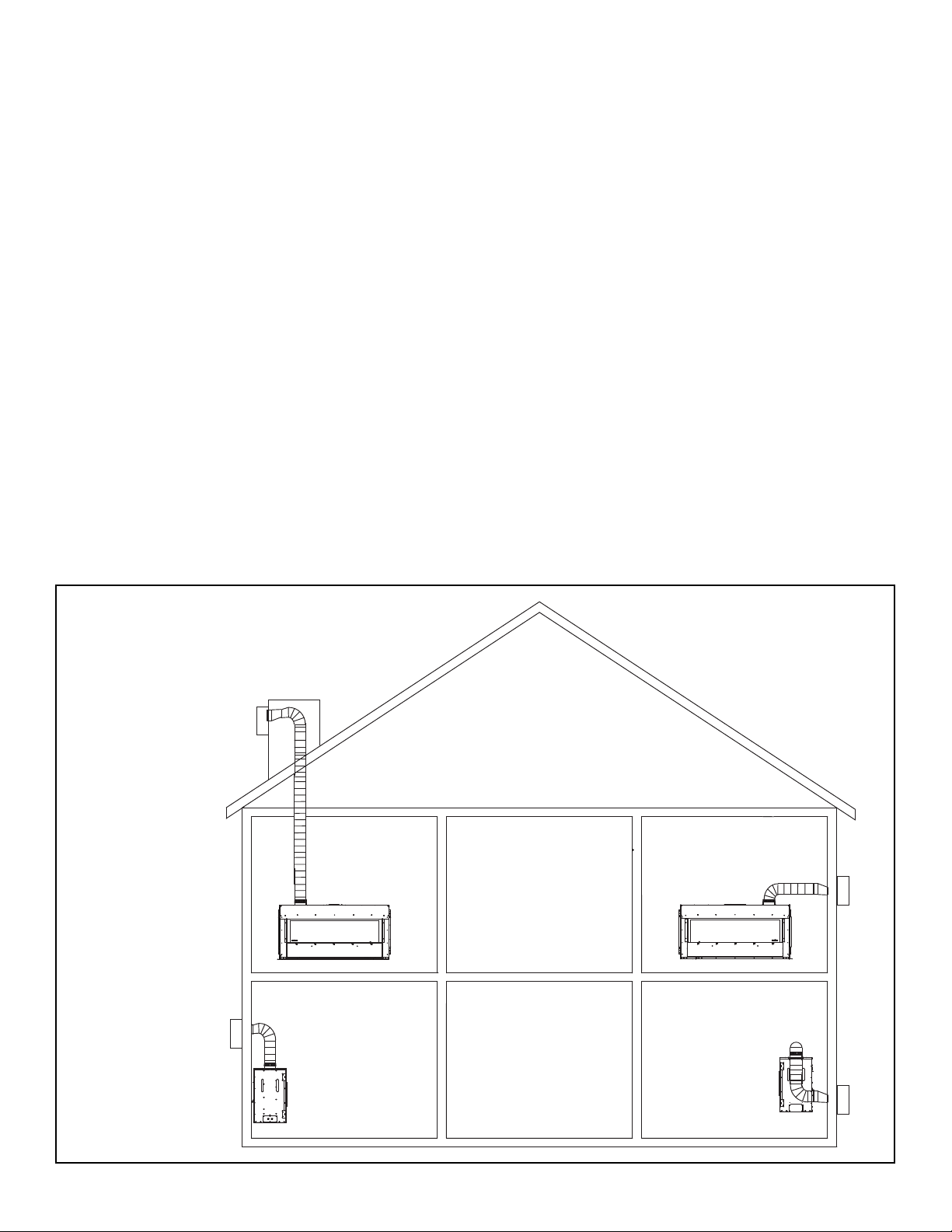
Possible Air Duct Runs/Locations
Maximum Duct Run Length: 35 FT.
Minimum Duct Run Length: 36 IN.
Clearance to exible duct = 0
Other Duct Option
Metal Round And Oval Duct: A combination of 6" round
and 6" oval air duct can be used in the duct run. Metal
duct components may be purchased from an HVAC supplier.
Note: Support duct at intervals of no greater than 4 feet,
with no more than 1/2" sag between supports as required
by local code. Tape all seams with aluminum tape (1-1/4"
minimum width, or as specied by local codes).
*CAUTION! Risk of Overheating! Tape seams to pre-
vent overheating and shut down of appliance.
2
Hearth & Home Technologies • HEAT-OUT-PRIMO Instructions • 2310-929 Rev. i • 1/19
Preliminary Preparation
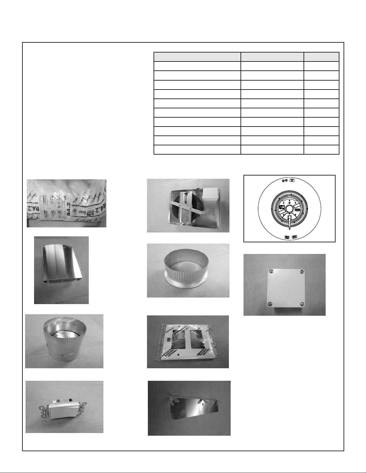
Contents of HEAT-OUT-PRIMO
CAUTION! Do not install damaged
components.
If any parts are missing or damaged, contact
your dealer before starting installation. DO NOT
install a damaged kit.
DESCRIPTION SERVICE PART NO. QTY
6 in. Round Duct 659-200 1
Blower Base Assembly SRV4086-021 1
Cover Assembly 4086-022 1
Unit Collar 659-125 1
Damper Assembly 4086-316 1
Wall Switch Plate 2155-511 1
Wall Switch 2310-210 1
**Vinyl Siding Shield 4086-140 1
*Fan Assembly HEAT-OUT-UPG 1
*Junction Box Assembly SRV2326-304 1
*Included in Blower Base Assembly
**Not included with this kit.
659-200 6 Inch Round Duct
4086-022 Cover Assembly
SRV4086-021 Blower Base Assembly
Fan Assembly - Order HEAT-OUT-UPG
659-125 Unit Collar
SRV2326-304 Junction Box Assembly
2155-511 Wall Switch Plate4086-316 Damper Assembly
NOTICE: Install vinyl siding heat shield
only with vinyl siding.
2310-210 Wall Switch
3
4086-140 Vinyl Siding Shield
Hearth & Home Technologies • HEAT-OUT-PRIMO Instructions • 2310-929 Rev. i • 1/19
*
Heat-Out-Primo
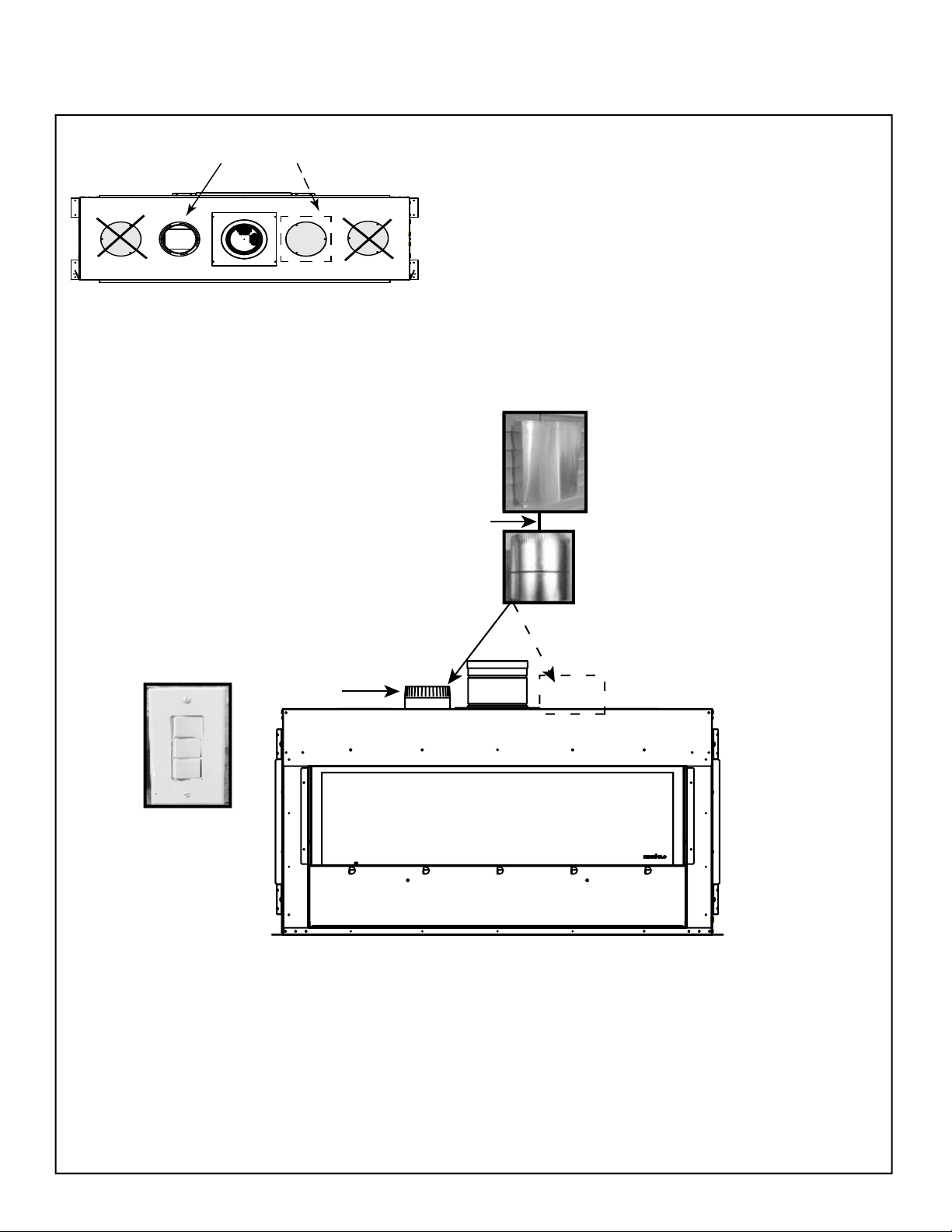
HEAT-OUT-PRIMO Feature - Configuration
* = Optional HEAT-OUT-PRIMO location
X = Not for HEAT-OUT-PRIMO
WARNING! Risk of Overheating! Damper MUST
be installed with crimped side up. Damper will not
function properly.
WARNING! Risk of Fire! Verify damper is operational. Overheating will occur if damper does not
open and close.
Heat-Out-Primo Only
**ATTACH WITH
ZIP TIE AT
DAMPER
Heat-Out-Primo
***DAMPER
*
Collar
LED Color Switch
*The Heat-Out-Primo may be installed in either position shown above.
*Note: Remove only one of the two Heat-Out seal plates if installing
the HEAT-OUT-PRIMO. The other plate must remain installed.
** Use included zip ties to attach the flex duct to the damper.
***Verify damper is operational and no obstructions, such as screws,
are present.
4
Hearth & Home Technologies • HEAT-OUT-PRIMO Instructions • 2310-929 Rev. i • 1/19

Heat-Zone-Primo
Heat-Out-Primo
***DAMPER
Heat-Zone-Primo CollarHeat-Zone-Primo Collar
Wall Switch
HEAT-ZONE-PRIMO &
PowerFlow Heat
Management Toggle
LED COLOR
SWITCHES
**ATTACH WITH
ZIP TIE AT
DAMPER
Heat-Zone-Primo
HEAT-OUT COLLAR
*The Heat-Out-Primo may be installed in either position shown above.
** Use included zip ties to attach the flex duct to the damper.
*** Verify damper is operational and no obstructions, such as screws,
are present.
*Note: Remove only one of the two Heat-Out seal plates if installing
the HEAT-OUT-PRIMO. The other plate must remain installed.
*
HEAT- O UT-PRIMO Incorporated with HEAT-ZONE-PRIMO
Heat-Out-Primo
*
* = Optional HEAT-OUT-PRIMO location
X = Not for HEAT-OUT-PRIMO
WARNING! Risk of Overheating! Damper MUST
be installed with crimped side up. Damper will not
function properly.
WARNING! Risk of Fire! Verify damper is operational. Overheating will occur if damper does not
open and close.
5
Hearth & Home Technologies • HEAT-OUT-PRIMO Instructions • 2310-929 Rev. i • 1/19
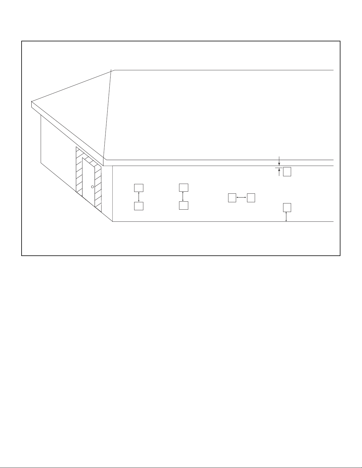
Power Vent Termination Clearances
PV = PVLP-SLP
HO = HEAT-OUT-PRIMO
1/2 IN. MIN. TO SOFFIT
HO
HO
PV
PV
24 IN. MIN.24 IN. MIN.
HO
HOPV
6 IN. MIN.
HO
12 IN. MIN.
GRADE
6
Hearth & Home Technologies • HEAT-OUT-PRIMO Instructions • 2310-929 Rev. i • 1/19