

Hearth & Home Heat-Zone 240V Installation And Operation Instructions Manual
Heat-Zone® 240V Air Duct Kit
FLOOR REGISTER
TWO DUCT KITS
WALL REGISTER
WALL
REGISTER
WALL
REGISTER
CEILING REGISTER
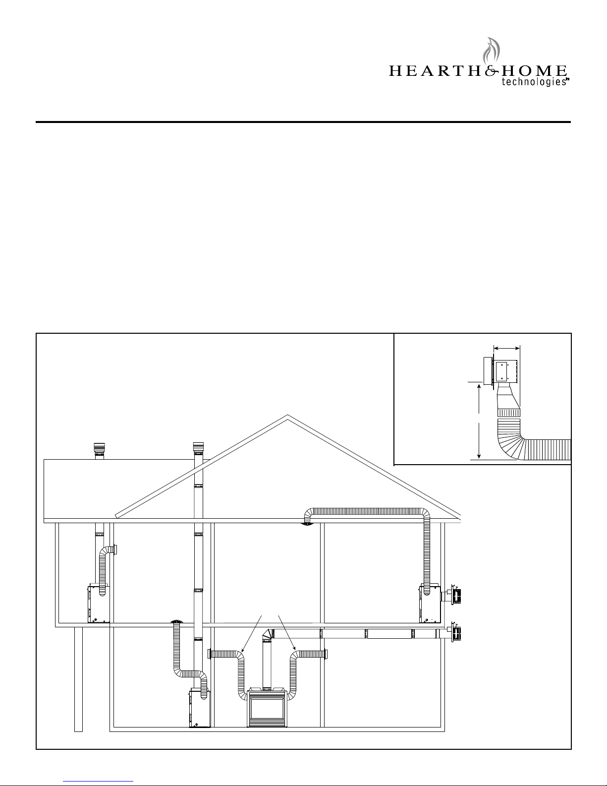
457 mm
171 mm
MINIMUM SPACE
REQUIRED FOR
90 DEGREE BEND
INSTALLATION AND
OPERATION INSTRUCTIONS
Approvals
The Heat-Zone® 240V air duct kit is approved for use on
Heat & Glo Models XLR-AU, XLR-PLUS, XLR-CE, RED40AU, 6TRSI-AUD, MEZZO-AU, 6000, 350 and 550 series
gas heaters.
Introduction
The Heat-Zone® 240V accessory kit conveys warm air
from the heater through air duct(s) to remote locations in
the same room or other rooms of the building. See Figure
®
1. One or two Heat-Zone
240V kits can be installed on
the heater.
Possible Air Duct Runs/Locations
Preliminary Preparation
Contents of kit:
• 6 meters of 152 mm Round Duct
• Fan Housing Assembly
• Junction Box
• Air Register
• Heater Duct Collar
• Duct Adapter - (round to oval)
• Hardware Bag
• IPI Plus Auxiliary Jumper
NOTICE! If any parts are missing or damaged, contact your
dealer before starting installation. DO NOT install a damaged kit.
Figure 1
Hearth & Home Technologies • Heat-Zone-240V Air Duct Kit • 299-900 Rev. H • 11/15 1
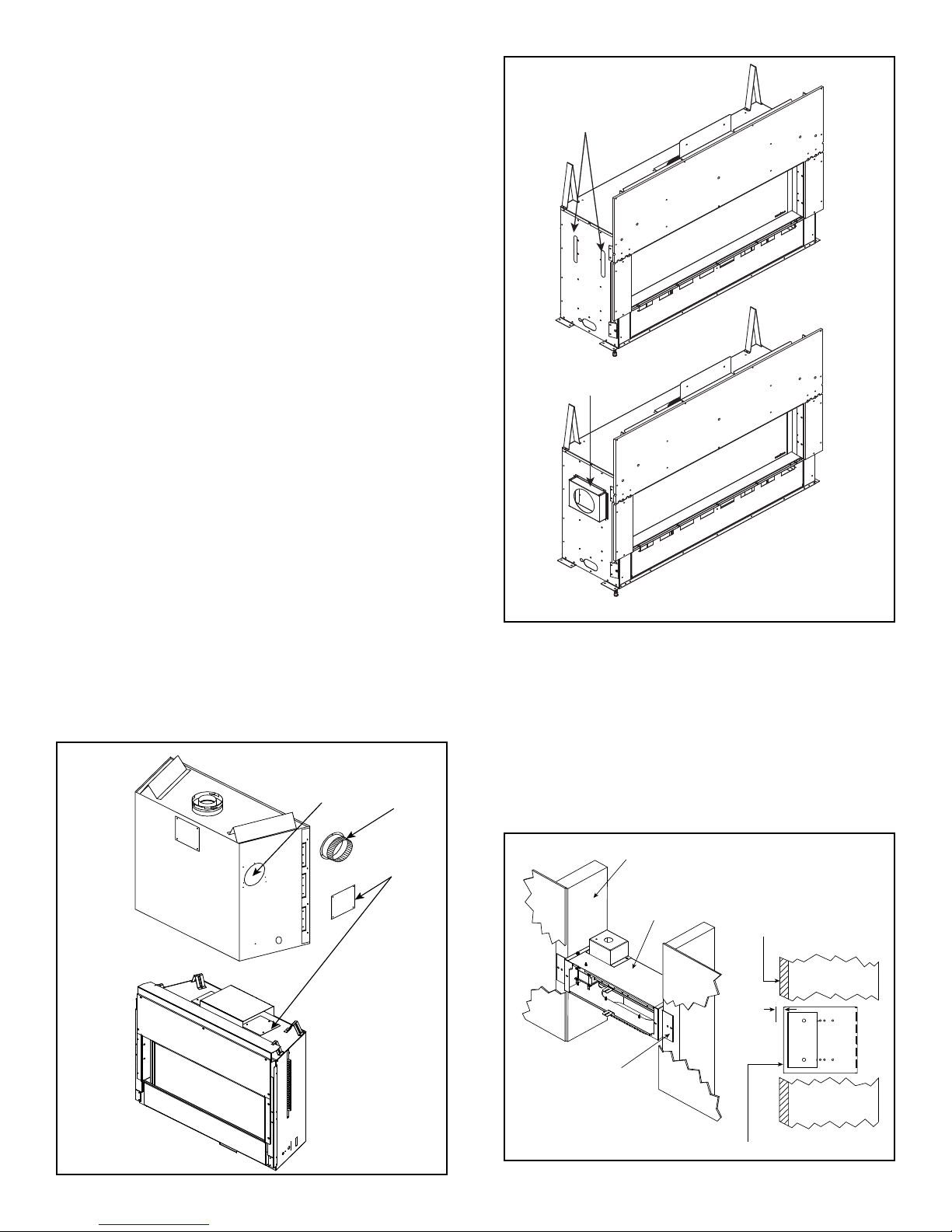
COVER
PLATE
DUCT
COLLAR
6000 SERIES
XLR-AU
KNOCKOUT
FAN HOUSING
ADJUSTABLE
MOUNTING BRACKET
FINISHED SURFACE
FRONT OF FAN HOUSING
6 mm
2 x 6 WALL
HEAT ZONE® LOCATION
LEFT AND RIGHT SIDES
HEAT ZONE
®
ADAPTER BOX
The Heat-Zone® 240V kit is tested and safe when installed
in accordance with this installation manual. This kit is
carefully engineered and must be installed only as speci-
ed. Modifying the kit or any of its components will void
the warranty, and may possibly cause a re hazard.
CAUTION: Installation of this appliance should only be
carried out by an authorized person. All relevant codes
and regulations laid down by the gas piping authorities,
municipal building regulations, electrical wiring regulations and the requirements of the AS5601 Gas Installation
code must be observed.
Preliminary Preparation
1. Plan the location of the heater and the warm air duct
run(s). See Figure 1 for potential installation options.
Venting Guidelines:
MAXIMUM Duct Run = 6 m for useful heat output.
Insulated duct included with kit will not lose signicant heat.
MINIMUM Duct Run = None: For runs out from the heater
to adjacent room OR down to the room below.
MINIMUM Duct Run = 787 mm top of heater to room above.
• Maintain smooth turns in duct to ensure maximum heat
output.
• If using optional non-insulated pipe, as described in
Step 6, heat loss will occur and shorter duct runs will
yield higher heat output.
Installation
1. Remove the cover plate or knockout from the side or
top of the heater and discard it.
2. Center the duct collar around the exposed hole and
attach it to the heater with 3 screws. NOTE: Do this
BEFORE nal positioning of the heater. See Figure 2.
MEZZO-AU
See MEZZO-AU Installation
Manual for full instructions.
Figure 3
3.
Determine the location for the air register/fan housing
as-
sembly. Cut a 127 x 346 mm hole between framing
members (wall studs or oor joists).
4. Mount and secure the fan housing assembly to framing
members so the front surface is 6 mm below the nished wall or oor surface. Use the adjustable mounting
brackets and screws provided in the kit. See Figure 4.
NOTE: The brackets can be rotated 180º and mounted
to the back side of the framing member if necessary.
Hearth & Home Technologies • Heat-Zone-240V Air Duct Kit • 299-900 Rev. H • 11/152
Figure 2
Figure 4
 Loading...