

Hearth & Home GO24-IPI-NG, GO318-IPI-NG, GO30-IPI-NG, GO324-IPI-NG, GO330-IPI-NG Installation Instructions Manual
...
Hearth & Home Technologies • Grand Oak Gas Log Sets • 4004-317 REV B. 5/2013
1
TM
Models:
GO24-IPI-NG or LP,
GO30-IPI-NG or LP
GO318-IPI-NG or LP
GO324-IPI-NG or LP
GO330-IPI-NG or LP
Grand Oak Gas Log Sets
Installation
Instructions
Check with your local building code agency before you begin installation to ensure compliance with local codes, including
the need for permits and follow-up inspections. If you encounter any problems regarding code approvals, or if you need
clarification of any of the instructions contained here, contact the Technical Services Dept., Hearth & Home Technologies
Inc., www.hearthnhome.com.
Note: An arrow () found in the text signifies change in
content.
DO NOT DISCARD THIS MANUAL
CAUTION
• Im portan t operating
a n d m a i n t e n a n c e
instructions included.
•
Leave this manual with
party responsible for
use and operation.
•
Rea d , understand
an d fo ll ow th es e
instructions for safe
i ns ta ll at io n a n d
operation.
DO N
O
T
D
IS
CA
R
D
If the information in these instructions is not followed exactly, a
fire may result causing property
damage, personal injury, or death.
• Do not store or use gasoline or other flammable vapors and liquids in the vicinity of
this or any other appliance.
• What to do if you smell gas:
- Do not try to light any appliance.
- Do not touch any electrical switch. Do not
use any phone in your building.
- Immediately call your gas supplier from
a neighbor’s phone. Follow the gas
supplier’s instructions.
- If you cannot reach your gas supplier, call
the fire department.
• Installation and service must be performed
by a qualified installer, service agency, or
the gas supplier.
WARNING
HOT! DO NOT TOUCH.
SEVERE BURNS MAY RESULT.
CLOTHING IGNITION MAY RESULT.
WARNING
• Keep children away.
• CAREFULLY SUPERVISE children in same room as
appliance.
• Alert chil d r e n and adults to haza r d s of high
temperatures.
• Do NOT operate with protective barriers removed.
• Keep cl o t h i n g , fu r n i t u r e , dr a p e r i e s and ot h er
combustibles away.
Glass and other surfaces are hot during
operation and cool down.
Installation and service of this
appliance should be performed by
qualified personnel. Hearth & Home
Technologies suggests NFI certified
or factory-trained professionals,
o r t e ch n ic i an s
s u p e r v i s e d b y
an N FI c er ti f ie d
professional.
In the Commonwealth of Massachusetts:
• This appliance must be installed by a licensed plumber
or gas fitter.
• The chimney flue damper, when used with gas logs, will
be welded open or completely removed.
• A CO detector shall be installed in the room where the
appliance is installed.
Hearth & Home Technologies • Grand Oak Gas Log Sets • 4004-317 REV B. 5/2013
2
Read this manual before installing or operating this appliance.
Please retain this owner’s manual for future reference.
Congratulations on selecting a Hearth & Home Technologies
gas log set—an elegant and clean alternative to burning
wood. The Hearth & Home Technologies gas log set you
have selected is designed to provide the utmost in safety,
reliability, and efficiency.
As the owner of this new gas log set, you’ll want to read and
carefully follow all of the instructions contained in this owner’s
manual. Pay special attention to all cautions and warnings.
This owner’s manual should be retained for future reference.
We suggest you keep it with your other important documents
and product manuals.
The information contained in this owner’s manual, unless
noted otherwise, applies to all models and gas control
systems.
Your new gas log set will give you years of durable use and
trouble-free enjoyment. Welcome to the Hearth & Home
Technologies family of appliance products!
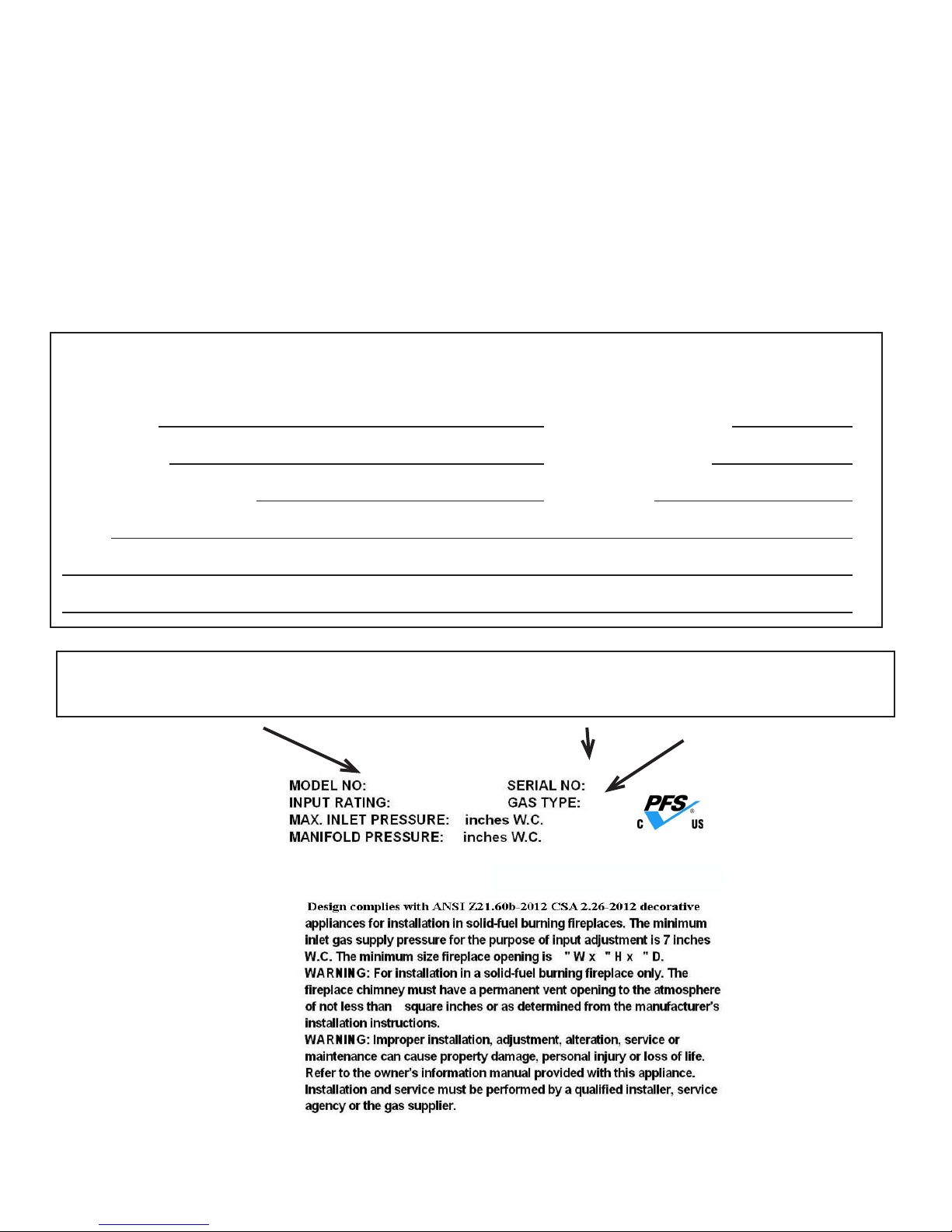
Listing Label Information/Location
The model information regarding your specific gas log set can be found on the rating plate.
Congratulations
Homeowner Reference Information
Model Name: Date purchased/installed:
Serial Number: Location on appliance:
Dealership purchased from: Dealer phone:
Notes:
We recommend that you record the following pertinent
information about your gas log set:
Model #
Serial #
Gas Type
HEARTH AND HOME TECHNOLOGIES
Angier, NC 27501
Hearth & Home Technologies • Grand Oak Gas Log Sets • 4004-317 REV B. 5/2013
3
A. Design and Installation Considerations
The Gas Log Hearth Kit consists of the following:
• Log Set
• Burner/Pan Assembly
• Grate Assembly
• Rock Wool
• Sand (NG only)
• Lava Rock
• Damper Stop
• Vermiculite
• Platinum Embers
B. Tools and Supplies Needed
Tools and supplies normally required for installation:
Pliers
Phillips screwdriver
Tape measure
Crescent wrenches
Gas shutoff valve
Non-corrosive leak check solution
3/4 in. wrench, 7/16 in. wrench
Improper installation, adjustment, alteration, service
or maintenance can cause injury or property damage.
Refer to the owner’s information manual provided with
this appliance. For assistance or additional information
consult a qualified installer, service agency or the gas
supplier.
WARNING
Sharp Edges
• We a r protective gloves
and safety glasses during
installation.
CAUTION
HOT! DO NOT TOUCH.
SEVERE BURNS MAY RESULT.
CLOTHING IGNITION MAY RESULT.
WARNING
• Keep children away.
• CAREFULLY SUPERVISE children in same room as
appliance.
• Alert chil d r e n and adults to haza r d s of high
temperatures.
• Keep cl o t h i n g , fu r n i t u r e , dr a p e r i e s and ot h er
combustibles away.
Glass and other surfaces are hot during
operation and cool down.
C. Important!
• Do not remove any of the attached metal plates, which
contain important safety and operating information.
• Keep the appliance area clear and free of all combustible
materials, gasoline and other flammable vapors and
liquids.
• Any safety screen or guard removed during servicing must
be replaced before operation.
• A qualified service technician must perform installation
and repair. The appliance should be inspected and cleaned
annually by a qualified service technician. More frequent
cleaning may be required due to excessive lint, dust, pet
hair, etc. It is imperative that the control compartments,
burners and air passageways are unobstructed during
operation.
- Review proper placement of logs, rockwool, lava rock
and vermiculite.
- Check the wiring.
- Ensure there are no gas leaks.
- Ensure the flow of combustion and ventilation air is not
obstructed (front grilles and vent caps).
• Before installing into a solid fuel burning fireplace, the
chimney and firebox should be inspected and cleaned to
remove soot, creosote, ashes, paint, bird nests etc.
• Annual examination of the chimney must be performed
by a qualified agency to ensure proper ventilation of flue
gases created by this appliance.
Fire Risk
Exhaust Fumes Risk
• Do NOT use this appliance as a “ventfree” heater.
The flue must be permanently open according
to Tables 1 and 2.
WARNING
• Have the chimney and adjacent structure inspected
and cleaned by qualified professionals. Hearth & Home
Technologies recommends that NFI or CSIA certified
professionals, or technicians under the direction of certified
professionals, conduct a minimum of an NFPA 211 Level 2
inspection of the chimney.
• Replace component parts of the chimney and fireplace as
specified by the professionals.
• Ensure all joints are properly engaged and the chimney
is properly secured.
• Do not allow fans to blow directly into the fireplace. Avoid
any drafts that alter burner flame pattern.
• Do not use a blower insert, heat exchanger insert or other
accessories not approved for use with this appliance.
Hearth & Home Technologies • Grand Oak Gas Log Sets • 4004-317 REV B. 5/2013
4
D. Appliance Certification
This appliance is design certified by PFS under the ANSI
Z21.60b-2012 or CSA 2.26b-2012, Decorative Appliances
for Installation in Solid-fuel Burning Fireplaces. Instal-
lation and the provisions for combustion and ventilation air
must conform to the National Fuel Gas Code, ANSI Z223.1/
NFPA 54, or the CSA B149.1, Natural Gas and Propane
Installation Code.
• This appliance must have a screen in place while the
appliance is in operation and, unless other provisions for
combustion air are provided, the screen shall have an
opening for introduction of combustion air.
• Solid fuels shall not be burned in a fireplace where a
decorative appliance is installed.
• If glass doors are present, the glass doors must be fully
opened while appliance is in operation.
Do NOT use this appliance if any part has been under
water. Immediately call a qualified service technician
to inspect the appliance and to replace any part of the
control system and any gas control which has been
under water.
WARNING
E. Gas Supply Connection
A 3/8 in. flared fitting has been installed on the gas valve
inlet at the factory. Ensure fittings are of the appropriate size
and type on the gas line connection. If the tubing has to be
cut to length be sure to use the proper cutting and flaring
tool. Also, be careful not to crimp the tubing while bending. If
the tubing becomes crimped, do not use for installation.
Gas resistant pipe compound must be used on all threaded
male connections to ensure a tight seal.
F. Gas Pressure
Proper input pressures are required for optimum appliance
performance. Gas line sizing requirements need to be made
following NFPA51.
Fire Risk
Explosion Risk
Verify inlet pressures.
• Hi g h pr e ss ur e ma y cau s e ov e rf ir e
condition.
• Low pressure may cause explosion.
Install regulator upstream of valve if line
pressure is greater than 1/2 psig.
WARNING
Fire Risk
Explosion Risk
High pressure will damage valve.
• Disconnect gas supply piping BEFORE
pressure testing gas line at test pressures
above 1/2 psig.
• Close the manual shutoff valve BEFORE
pressure testing gas line at test pressures
equal to or less than 1/2 psig.
WARNING
• Gas Supply Pressure: Minimum inlet gas supply pressure
must be 7.0 in. W.C. for natural gas or 11 in. W.C. for LP
gas for the purpose of input adjustment. Maximum inlet
gas pressure must not exceed 10.5 in. W.C. for natural
gas or 13 in. W.C. for LP gas. The gas line supplying the
appliance must be sufficient size to furnish the appropriate
supply pressure to the appliance while operating in the
“High” setting.
• Pressure tap screws must be closed before turning gas
on to the appliance.
• Gas Line Pressure Test: Perform pressure test according
to state and local code (if pressure exceeds 1/2 in. psi (3.5
kPa)) before appliance is connected. Be sure to release
air pressure from the gas line before connection is made
to the appliance. Excessive pressure will damage the gas
control and may cause a gas leak.
• Gas Leak Test: Make sure the gas connections are tight.
Turn on the gas and coat each joint with a non-corrosive
gas leak check solution. Air bubbles will form indicating
any leaks. DO NOT USE A FLAME OR ANY TYPE OF
IGNITION SOURCE TO CHECK FOR LEAKS. All leaks
must be corrected before proceeding with installation.
• The appliance must only be installed in a solid-fuel burning
fireplace with the flue damper clamped open according
to Tables 1 and 2. The fireplace must be constructed of
non-combustible material.
• The minimum permanent free opening (in square inches)
that must be provided by the fireplace chimney or damper
to vent the flue gases is provided in Tables 1 and 2. If the
free opening is smaller than the specified area, do not use
this appliance.
• The damper must be removed or fixed in a manner in
which will secure it open. Some jurisdictions require the
damper to be removed or permanently welded fully open.
Check with state and local codes.
• Be sure that the chimney is completely unobstructed to
ensure proper ventilation of flue gases including carbon
monoxide (CO). CO (a poisonous gas) is tasteless,
odorless, colorless and undetectable without proper
equipment.
• Refer to Table 3 to determine minimum fireplace opening
requirements before proceeding.
Hearth & Home Technologies • Grand Oak Gas Log Sets • 4004-317 REV B. 5/2013
5
Asphyxiation Risk
This appliance produces carbon monoxide
(CO).
• The free opening areas (in square inches)
of the chimney damper as shown in the
following tables must be met.
• User must make sure damper is locked
open.
• The installer is responsible to ensure
proper ventilation of flue gases before
appliance is used.
Fire needs to draft properly fo r sa f e
operation.
WARNING
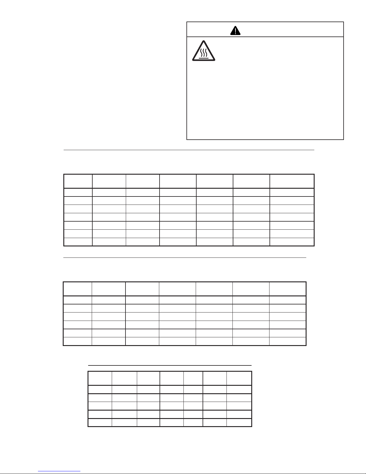
Table 1 for Factory Built Fireplaces
Free Opening Area (in square inches) of Chimney Damper for Venting combustion Products from Decorative
Appliances for Installation in Solid Fuel Burning Fireplaces.
Chimney Ht.
(Feet)*
GO318
LP Gas
GO 318
Natural Gas
GO 24 & 324
LP Gas
GO 24 & 324
Natural Gas
GO 30 & 330
LP Gas
GO 30 & 330
Natural Gas
10 35.3 not approved 35.3 not approved 44.2 not approved
15 26.4 38.5 26.4 38.5 32.2 45.4
20 22.1 31.2 22.1 31.2 26.4 37.4
25 18.1 27.3 18.1 27.3 22.9 31.2
30 17.3 24.6 17.3 24.6 20.4 28.3
35 15.9 22.1 15.9 22.1 18.9 25.5
40 15.2 20.4 15.2 20.4 18.1 23.8
Table 2 for Masonary Built Fireplaces
Free Opening Area (in square inches) of Chimney Damper for Venting combustion Products from Decorative
Appliances for Installation in Solid Fuel Burning Fireplaces.
Chimney Ht.
(Feet)*
GO318
LP Gas
GO 318
Natural Gas
GO 24 & 324
LP Gas
GO 24 & 324
Natural Gas
GO 30 & 330
LP Gas
GO 30 & 330
Natural Gas
6 49.2 64 49.2 64 56.6 71.4
8 45.5 59.7 45.5 59.7 52.4 66.9
10 41.7 54.3 41.7 54.3 48.2 60.2
15 37.7 48.8 37.7 48.8 43.2 54.1
20 34.3 44.4 34.3 44.4 39.8 49.1
30 31.2 40.3 31.2 40.3 35.9 44.5
* Height is measured from the hearth to the top of the chimney.
Minimum height is 6 ft.
G. Negative Pressure
Negative pressure results from the imbalance of air available for the fireplace to operate properly. Causes for this
imbalance include:
• Exhaust fans (kitchen, bath, etc.).
• Range hoods.
• Combustion air requirements for furnaces, water heaters
and other combustion appliances.
• Clothes dryers.
• Loc a ti on o f r et u rn -a i r v en t s t o f ur n ac e or ai r
conditioning.
• Imbalances of the HVAC air handling system.
• Upper level air leaks: recessed lighting, attic hatch
opening, duct leaks.
Table 3 for Minimum Fireplace Dimensions
Log Set
Front
Opening Depth Height
Rear
Width
Natural
BTU
Propane
BTU
GO318 32 in. 23 in. 22 in. 21 in. 88,000 80,000
GO24 34 in. 20 in. 18 in. 22 in. 73,000 61,000
GO30 40 in. 20 in. 18 in. 29 in. 80,000 70,000
GO324 34 in. 23 in. 22 in. 22 in. 88,000 80,000
GO330 40 in. 23 in. 22 in. 29 in. 92,000 82,000
Hearth & Home Technologies • Grand Oak Gas Log Sets • 4004-317 REV B. 5/2013
6
H. Inspect the Appliance and Components
• Remove the contents from the carton labeled “Burner”.
Attached to the burner are tags identifying the manufacturer
name, serial number, model number (including gas log
size), BTU ratings, gas type, etc.
• Review the attached tags before proceeding. Ensure
that all minimum fireplace dimension requirements are
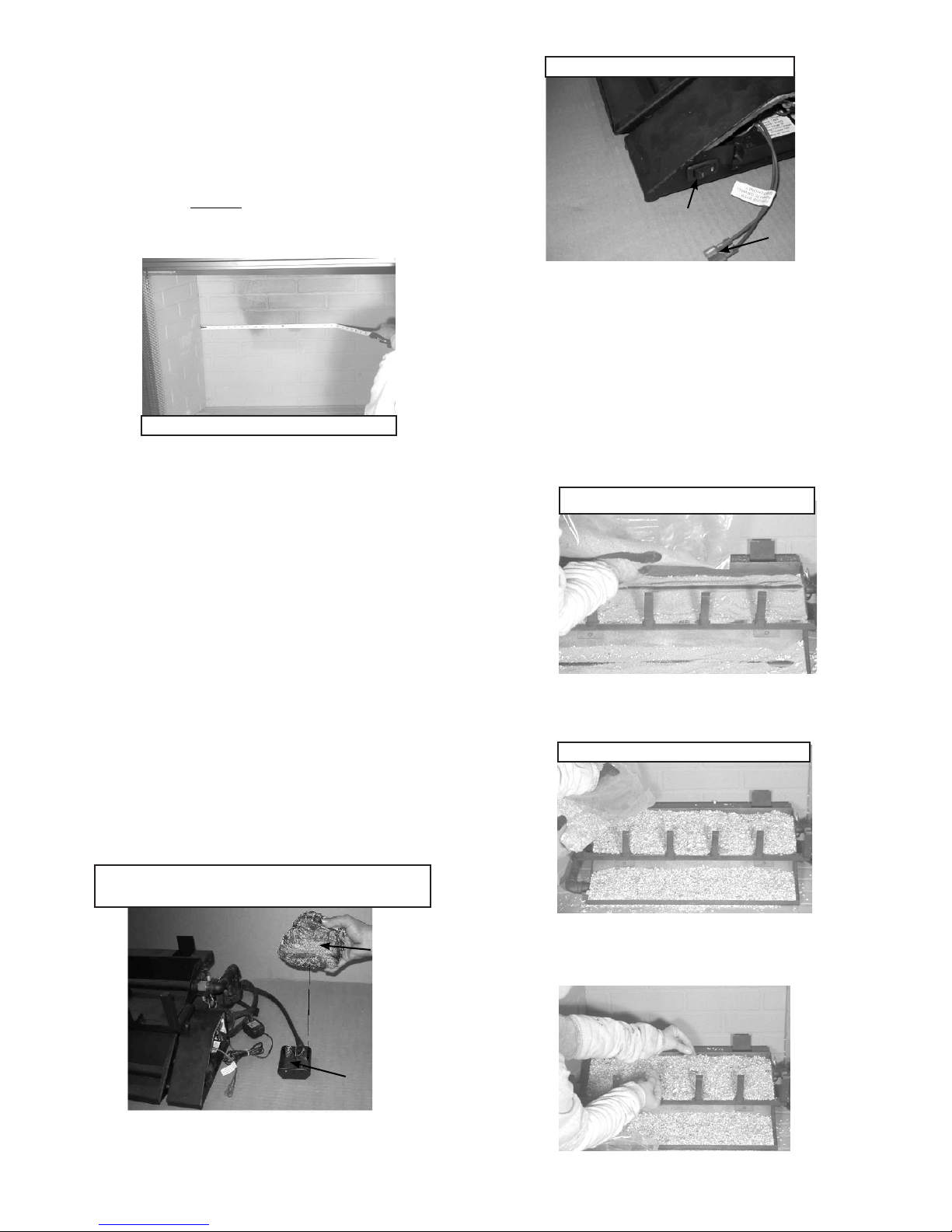
achieved using Table 3 . See Figure 1. Ensure the gas
type provided in the fireplace coincide with the gas type
marked on the tag.
I. For Natural Gas Installation (for all units)
• Pour sand into the burner pans to the point where the
burner pipe is covered. See Figure 5. Level the sand
from right to left to ensure an even flame pattern. At this
point the pan should be half full. Be sure not to cover pilot
assembly.
• Pour vermiculite over the sand in the pans until they are
full. See Figure 6.
Figure 1 Measure Firebox
Figure 6 Placing Vermiculite
Figure 5 Sand
Figure 7 Placing Rock Wool
• The burner is assembled with the controls installed at the
factory and is designed to connect one end of the 3/8 in.
supply line before placing inside the fireplace. Ensure the
connection is tightened using a 3/4 in. wrench.
• Place the burner towards the rear and center of the
fireplace and connect to the gas line. Follow instructions
in “F. Gas Pressure” to check for gas leaks.
• IPI models include a battery box which holds 2 “D” size
batterys. The battery box should be placed in the right
front corner of your fireplace and covered with the log
cover as shown in Figure 3.
• Lightly place dime-size pieces of rock wool evenly on top
of the sand and vermiculite to achieve a glowing ember
effect. See Figure 7.
Figure 3A Control Box for IPI
Battery Box Cover
Battery Box
Figure 3 Battery Box and Cover (for IPI units only)
On/Off Switch
Optional Remote
Connection
• An On/Off switch is provided as part of the assembly. It
is located on the front right side of the burner assembly
as shown in Figure 3A.
• Optional remote control system can be incorporated
with this system by connecting the remote system to the
connection wires shown in Figure 3A.
• For propane (LP) installations skip to “J for Propane Gas
Installation”.
Hearth & Home Technologies • Grand Oak Gas Log Sets • 4004-317 REV B. 5/2013
7
Note: For best results, do not pack down the rock wool.
The placement of rock wool can have an effect on flame
pattern and may need to be adjusted to achieve a desired
appearance.
Fire Risk
Explosion Risk
Personal Injury Risk
Failure to position the parts in accordance
with the diagrams provided with the log
pa ckages or fail ure to use onl y parts
approved with this appliance may result in
property damage or personal injury.
WARNING
• Inspect the pilot burner to ensure it is clear of any
rock wool.
• Remove the Platinum Bright Embers™ from the package.
For optimum performance peel each piece apart in layers
and lightly place on top of the vermiculite and rock wool
where the flame is blue. This will achieve the desired
realism.
• The gas burns at the point of the least resistance. In
case of an uneven flame pattern it may be necessary to
adjust the materials in the pans (using an object such as
a screwdriver) to achieve the desired effect.
• Place desired amount of lava granules on the floor of the
fireplace. DO NOT ALLOW THE GRANULES TO COME
IN CONTACT WITH THE FLAMES. (Lava granules may
contain moisture which, when heating, may cause it to pop
out during installation and set-up.) Ensure the controls
and switches are unobstructed after the granules are
installed.
• Place logs. See Sections S thru Y.
• Place accent logs around burner on floor of fireplace.
J. For Propane Gas Installation (for all units).
Fire Risk
Explosion Risk
Personal Injury Risk
An explosion could occur if a connection is
made directly to an unregulated propane
(LP) tank.
WARNING
Pour vermiculite into each burner pan to the point where
each pan is completely full. Level the vermiculite from right
to left to ensure an even flame pattern. See Figure 6.
Note: Be sure to not cover the pilot assembly (located on
the right side of the burner pan, installed in the vertical
position) with vermiculite.
Fire Risk
Explosion Risk
Personal Injury Risk
Pour vermiculite into each burner pan (LP) to
the point where each pan is completely full.
Failure to do so may cause the lighting to be
delayed and this can be dangerous..
WARNING
K. Inspect the Venting System
The fireplace venting system is designed and constructed to
develop a positive flow adequate to remove flue gases to the
outside atmosphere. See fireplace installation instructions.
Note: For best results, do not pack down the rock wool.
The placement of rock wool can have an effect on flame
pattern and may need to be adjusted to achieve a desired
appearance.
Note: The state of Massachusetts requires that the
chimney flue damper, when used with gas logs, be welded
open or completely removed. In the Commonwealth of
Massachusetts this appliance must be installed by a
licensed plumber or gasfitter.
• Lightly place dime size pieces of rock wool evenly on top
of the vermiculite to achieve a glowing ember effect. See
Figure 7.
• Inspect the pilot burner to ensure it is clear of any
rock wool.
• Remove the Platinum Bright Embers™ from the package.
For optimum performance peel each piece apart in layers
and lightly place on top of the vermiculite and rock wool
where the flame is blue. This will achieve the desired
realism.
• The gas burns at the point of the least resistance. In
case of an uneven flame pattern it may be necessary to
adjust the materials in the pans (using an object such as
a screwdriver) to achieve the desired effect.
• Place desired amount of lava granules on the floor of the
fireplace. DO NOT ALLOW THE GRANULES TO COME
IN CONTACT WITH THE FLAMES. (Lava granules may
contain moisture which, when heating, may cause it to pop
out during installation and set-up.) Ensure that the controls
and switches are unobstructed after the granules are
installed. DO NOT COVER THE AIR MIXER LOCATED
ON THE LOWER LEFT SIDE OF THE BURNER.
• Place logs as shown in Sections S thru Z.
• Place accent logs around burner on floor of fireplace.

Hearth & Home Technologies • Grand Oak Gas Log Sets • 4004-317 REV B. 5/2013
8
L. Damper Stop Installation Instructions
Included in the burner assembly box is a damper stop clamp
which attaches to the damper as shown (Figure 8). Install
the clamp to the damper ensuring that the minimum requirements (Tables 1 and 2) are achieved. Use a 7/16 in. wrench
to secure the clamp to the damper. If the damper clamp provided does not fit your application, other means of securing
the proper opening must be provided by the installer.
Possible cures if spilling occurs:
• The damper needs to be opened further.
• The fireplace opening needs to be reduced by adding a
drop panel across the top under the lintel.
• The air supply from outdoors needs to be increased. Open
the outside air kit if the appliance is so equipped, or crack
open a door or window.
• If necessary, seek expert advice. Do not operate this
appliance.
Cleaning
• Periodic examination and cleaning of the venting system
of the fireplace should be done before initial use and at
least annually by a qualified agency.
A spillage test must be made before the installed
appliance is left with the consumer.
• Close all doors and windows in the home.
• Light the log set (see Lighting Instructions).
• After three minutes, test with a smoke match, smoke
candle, stick incense or cigarette 1 in. below the top of
the opening (lintel) moving across the full width. If spillage
(smoke down into the room) occurs, it will most likely be
near the top, outside corners.
Before cleaning the appliance, be sure it is turned
completely off. The pilot should also be turned off. The
unit must be completely cooled.
CAUTION
• Logs can get very hot. Handle only when they are
cool.
CAUTION
After burning, the logs become fragile. Take care in
handling.
CAUTION
M. Cleaning and Maintenance Instructions
Always remember:
• Do not place an y combust i ble mater ial near th e
appliance.
• Do not place any paper, trash or other material on the log
set or in the fireplace.
• Do not touch any part of the appliance when it is in
operation.
• Do not operate this appliance without the fireplace screen
closed.
Your appliance is designed to be virtually maintenance free,
although periodic visual inspection and cleaning is required.
Follow the instructions below for the correct procedures. An
annual examination and cleaning the venting system by a
qualified person is also recommended.
Do not allow soot to build up on the logs
Your logs require little care. Keep the burner assembly, logs
and burner area surrounding the logs clean by brushing with
a dry paint brush at least twice a year.
• Always turn off the gas to the pilot before cleaning.
For relighting, refer to Section P Thru R. Lighting
Instructions.
• Always keep the appliance clean and free from combustible
materials, gasoline and other flammable vapors and
liquids.
• Never obstruct the flow of combustion and ventilation air.
Keep the front of the appliance clear of all obstacles and
materials.
• Leave clearance of at least 36 in. from the front of the
fireplace.
Figure 8 Damper Stop Clamp
 Loading...