

Hearth & Home IPP, FPP Owner's Manual

Toll Free Technical Support
1 - 866 - 456 -9269
FPP
Bay View Freestanding
IPP
Bay View Insert / Built-In
FPP
Freestanding
IPP
Insert / Built-In
II or III
with Memory& Fan Trim
READ THIS ENTIRE MANUAL BEFORE YOU INSTALL AND USE YOUR HEATER.
FAILURE TO FOLLOW INSTRUCTIONS MAY RESULT IN PROPERTY DAMAGE,
BODILY INJURY OR EVEN DEATH!
Installation shall conform to CAN/CSA B365 Installation Code for Solid-Fuel-Burning Appliances and
Equipment in Canada and NFPA 211 Chimney, Fireplaces, Vents and Solid Fuel Burning Appliances in the USA.
Contact local building or fire officials to obtain a permit and information on any installation requirements
and installation inspection requirements in your area.
Rev. A, 01/2009
Rev. C, 09/2012
Toll Free Technical Support
1.877.427.3316
www.pelprostoves.com

Dear PELPRO Pellet Stove Owner:
CONGRATULATIONS on the purchase of your PELPRO MULTI-fuel pellet appliance! You have
selected the finest in residential wood pellet heating technology.
Let us pass on a few ―tips‖ concerning installing your stove and heating with wood pellets, corn or
wheat.
Whether you install your stove yourself or hire a professional installer, a quality installation is
a must for the safety of your family and for efficient, satisfactory operation of your stove.
Initial Burn Setup of the stove is the most important step to ensure the efficient and
satisfactory operation of your appliance for many years to come. Pellet Stoves ARE NOT
plug ‗n play.
Know the quality and characteristics of the fuel you burn. Corn, Wheat or even Wood Pel-
lets can vary greatly from company to company, from load to load and occasionally from bag
to bag.
Be extra diligent in your cleaning program.
Remember that a very high percentage of operational dilemmas with a pellet stove are
usually traced back to improper installation, poor quality fuel and/or lack of timely cleaning.
With just a minimum of daily care your PELPRO multi-fuel appliance will provide years of clean,
efficient, comfortable and environmentally sound heating.
Thank you for selecting a PELPRO wood pellet/multi-fuel appliance.
Sincerely,
Hearth & Home Technologies
Friendly Reminder:
A pellet stove / insert is not designed or tested as a primary source of heat. They are designed to
be a supplementary heat only. Please do not disconnect or remove your existing primary heat source.
Please do not disconnect or remove your existing primary heat source.
PelPro Appliances www.pelprostoves.com 2
2

T
ABLE
T
ABLE
OF
OF
C
C
ONTENTS
ONTENTS
GENERAL INFORMATION
SAFETY PRECAUTIONS
SAFETY TESTING
HOW YOUR PELPRO APPLIANCE WORKS
AUTOMATIC SAFETY FEATURES
SPECIFICATIONS
ELECTRICAL REQUIREMENTS
PRE PLANNING
PLANNING & INSTALLATION CHECKLIST
PLANNING EXHAUST SYSTEMS
TYPE
SAFETY PRECAUTIONS
DETERMING SIZE & DISTANCE
TERMINATION
PLANNING OUTSIDE AIR
APPLIANCE PLACEMENT
FLOOR PROTECTION
CLEARANCES TO COMBUSTIBLES
INSTALLATION
TOOLS OF THE TRADE
STEP BY STEP DIRECT VENT INSTALLATION
MOBIILE HOME
INSTALLATIONS OPTIONS
FIREPLACE INSERT—MASONRY OR FACTORY
BUILT-IN INSERT
OPERATION
BEFORE LIGHTING YOUR FIRST FIRE
USING THE ACUTRON CONTROLS
CHOOSING YOUR MODE OF OPERATION
MANUAL MODE
THERMOSTAT MODES (OPTIONAL)
UNDERSTANDING YOUR ACUTRON CONTROL
LIGHTING YOUR FIRE
PERFORMANCE ENHANCEMENT TIPS
FUEL
WOOD PELLETS
CORN AND OTHER BIOMASS
4
5
6
7
8
9
10
11
12
13
14
16
17
18
19
20
22
24
25
26
27
28
29
30
31
32
MAINTENANCE
REQUIRED ROUTINE CLEANING
2 TO 3 DAYS OR WEEKLY
PERIODIC MAINTENACE
1 TON, SEASONAL, BI-SEASONAL
FALL START-UP
SPRING SHUT-DOWN
YEARLY MAINTENANCE CONTRACTS
TROUBLE SHOOTING
REPLACEMENT PARTS
LIMITED WARRANTY
33
34
35
35
36
36
39
40
PelPro Appliances www.pelprostoves.com 3
3

S
AFETY
S
AFETY
IMPORTANT: Read, save and follow the instructions in this manual. It contains important safety, operating and
maintenance instructions you will need.
RECOMMENED: For your and your families protection and well being, Hearth & Home Technologies‘
highly recommends installing and maintaining both a smoke detector as well as a
CO2 detector.
BEFORE installing or having the pellet appliance installed contact the local building officials to obtain the
necessary permits and information on any installation restrictions or inspection requirements in your area
and notify your insurance company you have installed a pellet appliance.
This unit must be properly installed to prevent the possibility of a house fire. The instructions and local
building codes requirements must be strictly adhered to. Do not; use makeshift methods or material that
may compromise the installation.
When the pellet appliance is installed in a mobile home, the heater must be bolted to the floor, have out-
side air, and MUST NOT BE INSTALLED IN THE BEDROOM (Per H.U.D. requirements). Check with
local building officials.
NEVER try to repair or replace any part of the heater unless instructions for consumer are given in this
manual or instructed by Dansons Customer Service Department. A trained technician should do all other
work.
P
RECAUTIONS
P
RECAUTIONS
Educate all children of the danger of a high-temperature heater. Young children should be supervised
when they are in the same room as the heater.
This heater is designed and approved for pelletized wood fuel, shelled corn, or wheat only. Any other
type of fuel burned in this heater will void the warranty and safety listing. Keep foreign objects out of the
hopper.
NEVER use gasoline, gasoline-type lantern fuel, kerosene, charcoal lighter fluid, or similar liquids to start
or ―freshen up‖ a fire in this appliance. Keep all such liquids well away from the appliance while it is in
use.
This heater must be connected to a standard 115 V., 60 Hz 3-prong grounded electrical outlet in
accordance with local building codes, or in the absence of local codes, with the National Electrical Code,
ANSI/NFPA 70. A grounded surge-protection unit is recommended.
Do not use an adapter plug or sever the grounding prong on the electrical plug.
Do not route the electrical cord underneath, in front of, or over the heater.
Do not unplug the stove if you suspect a malfunction.
Push the ―OFF‖ Touch Pad and inspect the heater.
The heater will not operate during a power outage. If a power outage does occur, check the heater for
smoke spillage and open a window if any smoke spills into the room.
DO NOT operate the heater if you smell smoke coming from the heater. Push the ―OFF‖ Touch Pad,
monitor your pellet appliance, and call your local authorized dealer.
Do not place clothing or other flammable items on or near the heater. When installed with a thermostat
there is a possibility of the heater turning on and igniting any items placed on or near the unit.
CAUTION: To prevent fingers, clothing or other objects from coming in contact with the auger; your appliance is equipped with a shutoff switch which stops the auger when the hopper lid is open. THE AUGER
IS CAPABLE OF CAUSING SERIOUS INJURY AND THIS SWITCH MAY NOT BE DISCONNETED
PelPro Appliances www.pelprostoves.com 4
4
DO NOT operate the stove if the flame becomes dark and sooty or if the firepot overfills with pellets. Push
DO NOT REMOVE OR COVER THIS LABEL
LIS TED PELLE T BUR NIN G R OOM HE ATER /FI REP LACE INS ERT POÊLE HOMOLOGUÉ AUTONOM E/ENCASTRABLE À COMBUSTIBLES SOLIDES CONVENANT
ALSO FOR US E I N M OBI LE HO MES ÉGALE MENT POUR INSTALLATION DANS LES MAISONS MOBILES.
CCI MODELS:/MODÈLES: [ ] FGB [ ] IGB [ ] FPP [ ] IPP OP TION S: CCI-I -3HZ & CCI 1-3VL BUILT IN FIREPLACE KITS / CONSTRUIT DANS DES KITS DE CHEMINEE
OPTIONS: CCI-MFBG MULTI-FUEL BURN GRATE / CCI-MFBG
TESTED PER UL 1482-00, ASTM E 1509-04, ULC S627-00, ULC S628-M93,
THIS PELLET BURNING APPLIANCE HAS BEEN TESTED AND LISTED FOR USE IN MANUFACTURED HOMES IN
ACCORDANCE WITH OREGON ADMINISTRATIVE RULES 814-23-900 T HROUGH 814-23-909.
A
B
UNIT
U
N
I
T
C
UNIT
FLOOR
PROTECTOR
E
B
B
A
D
F
B
B
A
B
UNIT
ALCOVE
B
B
INSTALL AND USE ONLY IN ACCORDANCE WITH MANUFACT URER’S INSTALLATION AND OPERATING INSTRUCTIONS.
---------------------------------------------------------- ----------------------------------------- ------------------------------
CONTACT LOCAL BUILDING OR FIRE OFFICIALS TO OBTAIN A PERMIT AND INFORMATION ON ANY INSTA LLATION
REQUIREMENTS AND INSTALLATION INSPECTION IN YOUR AREA.
--------------------------------------------------------------- ------------------------- ----------- ----- ----------------------- ---
WARNING: DO NOT INSTALL APPLIANCE IN A SLEEPING R OOM.
---------------------------------------------------------- ----------------------------------------- ------------------------------
FOR USE WITH 1/4. (6 MM) – 3/8 ’ (10MM) PELLETIZED WOOD FUEL.
MAX. INPUT RATING APPR OXIMATELY 4.5 – 5 LB.’S P ER HOUR USING 8,500 - 8,770 BTU/LB OF PELLET FUEL
ALSO FOR USE WITH SHELLED CORN AND WHEAT, UNDER 14% MOISTURE, USING MULTI-FUEL GRATE SYSTEM
MAX. INPUT RATING APPR OXIMATELY 6.5 – 7 LB.’S P ER HOUR
USE OF OTHER FUEL MAY DAMAGE UNIT AND CAUSE A HAZARDOUS CONDITION.
---------------------------------------------------------- ----------------------------------------- ------------------------- -- --
INSTALL ON A NON-COMSUSTIBLE FLOOR PROTECTOR EXTENDING UNDER THE APPLIANCE AND 6 IN (152.4 MM)
BEYOND THE FRONT AND 6 IN (1 52 MM) TO EACH SIDE. DO NOT OBSTRUCT SPACE UNDER UNIT.
---------------------------------------------------------- ----------------------------------------- ---------------------------- ---
INSTALL AND USE ONLY IN A CODE COMPLYING MASONRY OR LISTED FACTORY- BUILT FIREPLACE. DO NOT
REMOVE BRICKS OR MORTAR FR OM MASONRY FIREPLACE, USE A NON-COMBUSTIBLE FLOOR PROTECTOR
EXTENDING BENEATH AND 6 INCHES TO THE FRONT OF THE UNIT. MUST ALSO INCLUDE A CHIMNEY LINER MEETING
TYPE HT REQUIREMENTS (2100 F) PER UL1777(US) OR ULC 8635 (CND).
---------------------------------------------------------- ----------------------------------------- --------------------------------
DO NOT CONNECT THIS UNIT TO A CHIMNEY FLUE SERVING ANOTHER APPLIANCE
---------------------------------------------------------- ----------------------------------------- --------------------------------
VENTING SYSTEM: TYPE PL. VENTING SYSTEM MUST BE USED. CLEARANCES FROM THE PL VENT ARE AS PER THE
VENT SYSTEM MANUFACTURER’S INSTRUCTIONS. SEE LOCAL BUILDING CODE AND APPLIANCE AND VENT
MANUFACTURER’S INSTRUCTIONS FOR PRECAUTIONS REQUIRED FOR PASSING VENTING SYSTEM THROUGH A
COMBUSTIBLE WALL OR CEILING.
---------------------------------------------------------- ----------------------------------------- ------------------------------
UNDER CERTAIN CONDITIONS OF USE, CREOSOTE BUILDUP MAY OCCUR RAPIDLY. INSPECT AND CLEAN VENTING
SYSTEM FRE QUENTLY.
---------------------------------------------------------- ----------------------------------------- ---------------------------- ---
KEEP VIEWING, ASH REMOVAL AND HOPPER DOORS TIGHTLY CLOSED DURING OPERATION.
REPLACE GLASS WITH CERAMIC GLASS ONLY.
---------------------------------------------------------- ----------------------------------------- ------------------------------
RATING: 120 VOLTS 2.0 AMPS 475 WATTS 60 HZ. ROUTE POWER SUPPLY CORD AWAY FROM UNIT.
---------------------------------------------------------- ----------------------------------------- ------------------------------
LIGHTING/SHUTDOWN INSTRUCTIONS : PLACE SMALL AMOUNT OF PELLETS IN GRATE-PLACE PROPR IETORY FIRE
STARTER ON PELLETS - PRES S ON TOUCH PAD - LIGHT - CLOSE DOOR. SELECT FEED R ATE AND FAN SPEED.
TO SHUT DOWN; PRESS OFF TOUCH PAD. REFER TO OPERATORS MANUAL, FOR ADDITIONAL DETAILS.
---------------------------------------------------------- ----------------------------------------- -------------------------------
CAUTION: MOVING PARTS MAY CAUSE INJURY. DO NOT OPERATE WITH PANEL OPEN.
DANGER: RISK OF ELECTRIC SHOCK. DISCONNECT POWER BEFORE SERVICING UNIT.
WARNING: HOT PARTS DO NOT OPERATE WITH SIDE PANELS OPEN.
MANUFACTURED BY: DATE OF MFG. / DATE OF FABRICATION
DANSONS INC. EDMONTON, AB, CANADA
1-877-303-3134
TESTÉ PAR UL 1482-00, ASTM E 1509-04, ULC- 627-00, ULC-S628-M93,
POUR L'CUTILISATION DANS LES MAISONS M ANUFACTURÉES SELON DES RÈGLES ADMINISTRATIVES DE L'C
ORÉGON 814-23-900 À 814-23-909
MINIMUM CLEARANCES TO COMBUSTIBLES / MINIMUM DE DÉGAGEMENTS JUSQU’A LA COMBUSTIBLE
A. 2 I N/PO, (50 MM) D. 16 IN/ PO, (406. 4 M M)
B. 6 I N/PO, (152 .5 MM) E. 2 I N/PO, (50 MM )
C. 2 I N/PO, (50 MM) F. 4 8.5 IN/ PO, (125 0 M M )
BUILT IN INSTALLATION: (REQUIRES ACI-3H2 OR ACI-3VL BUILT IN KITS) SEE INS TALLATION MANUAL FOR DETAIL.
FR AMING OP ENI NG: CLEAR ANCES :
HEIG HT = 26 ” SIDE & RE AR STAN D-OFF S TO FRA MING = 0”
WIDT H = 38” HOP PER T OP T O F RAM ING = 1 ”
DEP TH = 24 ”
INSTALLEZ SELON ET UTILISEZ SEULEMENT L'CINSTALLATION DE MANUFACTURER.S ET LES CONSIGNES
D'UTILISATION. LES FONCTIONNAIRES LOCAUX ENTREZ EN CONTACT AVEC BÂTIMENT OU FEU AU SUJET
DES RESTRICTIONS ET INSPECTION D'CINSTALLATION DANS VOTRE Z ONE.
_________ _________ _________ _________ ___________ ___________ ___________ _________ __________
AVERTIR N'INSTALLENT PAS L'CAPPAREIL DANS UNE SALLE DE SOMMEIL. POUR L'CUSAGE ONLV AVEC 1/4.
(6 MM). 3/8. (10MM) CARBURANT EN BOIS PELLETISÉ. L'UTILISATION De L'AUTRE CARBURANT PEUT END
OMMAGER L'UNITÉ ET CAUSER UN ÉTAT DANGEREUX.
ENTRÉE ÉVALUANT 8,500 – 8, 770 BTU/LB DE CARBURANT DE GRANULE.
_________ _________ _________ _________ ___________ ___________ ___________ _________ ___________
INSTALLEZ SUR UN PR OTECTEUR DE PLANCHER DE NON-COMSUSTIBLE ÉTENDANT SOUS L'CAPPAREIL ET LES
6 DEDANS (152.4 MILLIMÈTRE) AU DELÀ DE L'CAVANT. N'OBSTRUEZ PAS L'CESPACE SOUS L'CUNITÉ. INSTALLEZ
ET UTILISEZ SEULEMENT DANS UNE MAÇONNERIE D'CACQUIESCEMENT DE CODE OU UNE CHEMINÉE CONSTRUITE
PAR USINE ÉNUMÉRÉE. NE RETIREZ PAS LES BRIQUES OU LE MORTIER DE L'CUTILISATION DE CHEMINÉE DE
MAÇONNERIE UN PROTECTEUR NON-COMBUSTIBLE DE PLANCHER ÉTENDANT DESSOUS ET 6 POUCES À L'CAVAN
T DE L'CUNITÉ.
NE RELIEZ PAS CETTE UNI TÉ À UNE CONDUITE DE
CHEMI NÉE DE CHEMINÉE SERVANT UN AUTRE APPAREIL
CIRCUIT DE MISE À L'AIR LIBRE: UN CIRCUIT DE MISE À L'AIR LIBRE DE PL. DE TYPE DOIT ÊTRE UTILISÉ. LES DÉGAGEMENTS AVEC L'CÉVENT DE PL SONT SELON LES INSTRUCTIONS DU CIRCUIT DE MISE À L'AIR LIBRE MANUFACTURER.S.
VOIR LE BÂTIMENT LOCAL CODER ET LES INSTRUCTIONS D'CAPPAREIL ET D'CÉVENT MANUFACTURER.S POUR DES
PRÉCAUTIONS R EQUISES POUR PASSER LE CIRCUIT DE MISE À L'AIR LIBRE PAR UN MUR OU UN PLAFOND
COMBUSTIBLE.
DANS CERTAINES CONDITIONS D'CUTILISATION, L'CHABILLAGE DE CRÉOSOTE PEUT SE PRODUIRE RAPIDEMENT.
EXAMINEZ ET NETTOYEZ LE CIRCUIT DE MISE À L'AIR LIBRE FR ECUENTLY.
_________ _________ _________ _________ ___________ ___________ ___________ _________ ___________
ACTIONNEZ L'CUNITÉ SEULEMENT AVEC DES PORTES ENTIÈREMENT FER MÉES REMPLACENT LE VERRE PAR LE
VERRE EN CÉRAMIQUE SEULEMENT. ESTIMATION: 120 VOLTS 2, 0 AMPÈRES 60 HERTZ. COR DE D'CALIMENATION
D'CÉNERGIE D'CILTINÉRAIRE LOIN À PARTIR D'CUNITÉ. INSTRUCTIONS DE LIGHTING/SHUTDOWN: PLACEZ UN
PEU DE GRANULES SUR LA GRILLE - PLACEZ LE DÉMARREUR DU FEU DE P ROPRIETORY SUR DES GRANULES –
METTENT LE COMMUTATEUR "CMARCHE/CARRÊT" EN MARCHE - LUMIÈRE - À LA PORTE ÉTROITE. TOURNEZ LE
COMMUTATEUR DE CARBURANT AU BAS. POUR S'ARR ÊTER, COMMUTATEUR " CMARCHE/CARR ÊT " DE TOUR
POUR SE RAPPORTER HORS FONCTION AU MANUEL D'COPÉRATEURS, POUR LES DÉTAILS SUPP LÉMENTAIRES.
AVERTISSENT: LES PIÈCES MOBILES PEUVENT CAUSER DES DOMMAGES. NE
FONCTIONNEZ PAS AVEC LE PANNEAU OUVERT.
DANGER: RISQUE DE DÉCHARGE ÉLECTRIQUE. DÉBRANCHEZ LA PUISSANCE
AVANT UNITÉ D'CENTRETIEN.
AVERTISSEMENT: LES PIÈCES CHAUDES NE FONCTIONNENT PAS AVEC LE PANNEAU
OUVERT.
FABRIQUE PAR:
INDUSTRIES CANADIENNES DE CONFORT; EDMONTON, AB, CANADA
VAILLEZ À NE PAS ENLEVER NI À DISSIMULER CE COLLANT
the OFF Touch Pad and inspect the heater. (See Operating Your Stove). Soot or creosote may accumu-
late in the exhaust vent system when the stove is operated under incorrect conditions such as an extremely rich burn. The flame will have a lazy orange color with black tips. This indicates poor pellet fuel
combustion.
NEVER block free airflow through the open vents of the unit. The viewing door and ash pan must be
closed and latched during operation.
The pellet appliance exhaust system works with negative combustion chamber pressure and a positive
chimney pressure, therefore the exhaust system must be completely airtight and properly installed. All
exhaust system vent joints must be sealed, gas tight, with HI-TEMP RTV silicone sealant, and/or at least
3 sheet metal screws per joint and to the heater also.
Your heater requires periodic maintenance and cleaning (Refer to ‖Routine Cleaning‖ section of the
manual). Failure to maintain your heater may lead to smoke spillage in your home.
Disconnect the power cord from the electrical outlet before performing any maintenance. Pushing ‖OFF‖
Touch Pad does not disconnect all power to the heater.
BEFORE carrying out any maintenance or cleaning, allow the heater to cool. Ashes must be disposed in a
metal container with a tight lid and placed on a non-combustible surface or on the ground, well away from
all combustible materials, pending final disposal.
The exhaust system should be checked twice a year minimum for any build-up of soot or
creosote. Do not touch the hot surfaces of the heater.
NOTE: Hearth & Home Technologies grants no warranty, implied or stated, for the installation or
maintenance of your appliance, and assumes no responsibility of any consequential damage(s).
In accordance with the procedures and specifications listed in UL1482–00 & ASTM E 1509-04, and
ULC-S627-00 and ULC-S628-M93 for solid fuel room heater. Tested and listed for use in Manufactured
Homes in accordance with Oregon Administrative Rules 814-23-900 through 814-23-909. Hearth & Home
Technologies pellet stove has been independently tested and listed by INTERTEK (an accredited testing
laboratory) to UL, ULC and CSA standards. It is tested and listed for residential installation according to current
national and local building codes as:
A Freestanding Room Heater
A Mobile Home Heater.
Fireplace Insert
Built-in Insert
A Hearth Stove
The Safety Listing Label is located on the rear
inspection panel for model FPP, and on the
hopper panel for model IPP. Please read the
label carefully. It contains important information
about installation and operation of your
pellet appliance.
Note: Your STOVE’S serial number is located
on the safety label. Your appliance serial number
is preceded by a ―WH-― (example WH-00000).
(see diagram)
PelPro Appliances www.pelprostoves.com 5
S
AFETY
S
AFETY
T
ESTING
T
ESTING
5
H
as desiredas desired
Memory &
Fan Trim
Hopper
Auger
Auger Motor
Fan Motors
Exhaust
Air Intake
Ash Pan
―Super Grate‖
Burn Pot
Window
Tube Scraper
Heat Exchange
Tubes
Auger Cover
H
The operations and maintenance of your PelPro Series of multi-fuel appliance are unique and should not
be considered to be like a wood, coal, gas, electric, propane or oil heater, stove or appliance.
Cautions:
Do not try to operate your stove with viewing door open. Pellets will not feed under these
circumstances and a safety concern may arise from sparks or fumes entering room.
If you are not drawing combustion air from outside, care must be taken to allow for adequate air
make up, to avoid possible room air starvation when stove or other exhaust fans are in
operation.
It is highly recommended that you install a high quality smoke detector as well as a carbon
monoxide gas detector in the room where stove is installed. Care should be taken to make
sure detectors are in working order at all times.
FUEL CONSIDERATIONS
Your PelPro Series of Multi-fuel appliance is designed to burn the following:
1. Wood pellets that comply with the Pellet Fuel Industries standards.
2. A combination of up to 50/50 Wood Pellet and Shelled Corn
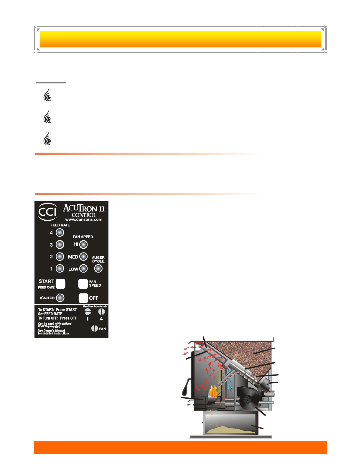
Fuel in the form of wood pellets or is stored in the hopper. An auger delivers the
pellets to the burn grate. The fuel rate, or heat output, is set by adjusting the feed
rate touch pad, (settings 1 to 4). A fan provides combustion air to the burn grate.
The amount of combustion air in the burn grate is adjustable and automatically
changes as the fuel rate changes. The higher the fuel rate, the larger the amount
of combustion air and visa versa. The fuel burns in the burn grate, producing
heat. Some heat radiates out the front of your stove. The majority of the heat
passes around the heat exchange tubes and air plenum around the firebox and is
then moved into the room by the room air fan. A small amount of heat must pass
out the exhaust of your stove, along with gases, into the atmosphere.
Your stove's heat output can be adjusted from setting 1-4, through the FEED
RATE touch pad, to vary your heat output from Low to High. The room air fan can
be manually adjusted through the FAN SPEED to run faster or slower to correspond to the amount of heat being produced. The room air fan is also on a limit
switch, controlled to run on high when the stove reaches higher temperatures and
then resume the speed you had selected once it cools to a lower temperature.
Your stove can run efficiently over
extended periods of time and at different heat output levels as long as
the fuel supply is uninterrupted and
timely cleaning and maintenance
is preformed. An example of how
improper cleaning effects operations
is; the exhaust pressure switch will
shut the pellet supply off and your
stove will shut off if the exhaust system becomes plugged.
PelPro Appliances www.pelprostoves.com 6
OW
Y
Y
OUR
OUR
OW
A
PPLIANCE
A
PPLIANCE
W
W
ORKS
ORKS
6
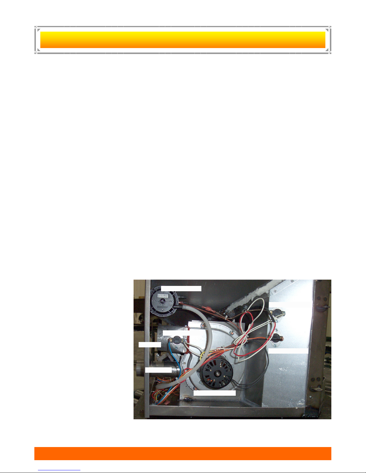
A
AcuTron Wiring Harness
Air Intake
Vacuum Switch
Low Lim it L1 20
High Lim it L 250
Fan Lim it F 140
Comb ustion Fan
Exha us t
UTOMATIC
A
UTOMATIC
S
AFETY
S
AFETY
F
EATURES
F
EATURES
L120 LOW LIMIT SWITCH
This limit switch is mounted on the exhaust blower housing and has 2 main functions:
Should the fire happen to go out, for any reason, this limit switch will shut the stove off when the exhaust
temperature drops below 120° F.
Upon starting the appliance, the AcuTron control board has a 15 minute ―Lighting Mode‖, if the stove
exhaust does not reach 120° F in that 15 minutes the stove will shut off. As soon as the stove
exhaust does reach 120° F, the limit switch opens and the AcuTron enters a 5 minute ―Safety Delay‖
mode.
F140 FAN LIMIT SWITCH
Your pellet appliance has a convection fan control limit switch. The room air fan's (F140) temperature limit
snap switch automatically operates the fan on high when your stove is producing heat faster than the fan is
carrying it into the room. This may occur when the heat control lever is set at [3 or 4] and the FAN SPEED is
set to a very low or off setting. After the fan runs at this automatic high setting a few minutes, it may cycle back
to its lower setting and may continue to cycle between [HIGH] and your selected setting. The circulation (room
air) fan cycling from high to low is a normal condition as well as a safety feature of your appliance.
To compensate for the fan cycling, adjust the FAN SPEED to a higher setting.
L250 HIGH LIMIT SWITCH
Your pellet appliance has a high temperature limit switch installed. If the temperature at the back of the firebox
reaches approximately 250° F., the switch will shut off the electricity going to the Vacuum Switch and to the
Auger Motor. The auger will automatically stop, and the appliance will shut down when the exhaust
temperature cools (120° F). If this happens call your dealer or Hearth & Home Technologies Customer Service
(1-877-427-3316).
IT IS IMPORTANT TO FIND THE REASON WHY THE UNIT OVERHEATED.
VACUUM SWITCH
This safety device (mounted on the back panel pillar) detects vacuum in the exhaust system, firebox, and air
intake. If the exhaust blower fails, the vent pipe becomes plugged, the viewing door is open, or if you are out
of pellets, this switch will sense that there is a lack of vacuum and will stop the auger from continuing to feed
pellets.
HOPPER LID SWITCH
This device is mounted inside the
hopper. and is connected to the
auger feed system.……
If the hopper lid is OPEN the switch
WILL STOP THE AUGER FEED
SYSTEM. This is to prevent fingers,
clothing or other objects from
coming in contact with the auger.
The auger is capable of causing
serious injury and this switch
MAY NOT be disconnected.
Left Hand Side View
/ Exhaust Fan Side
If the power does go out, the pellet appliance will stop running. When the power comes back
on, the stove will remember the function it was performing and return to that function.
PelPro Appliances www.pelprostoves.com 7
7
24‖
28 3/4‖
24‖
18 3/4‖
+
+
Shroud 1‖
+
+
24‖
6 1/2‖
7 3/4‖
8 1/4‖
3 ½‖
Exhau st
Air Inlet
8 1/4‖
Air Inlet
17 1/4‖
12 3/4‖
6 1/2‖
Exhau st
24 3 /4‖
24‖
24 3 /4‖
12 1/4‖ 10 3/4‖
+
+
24‖
8 1/4‖
Air Inlet
17 1/4‖
12 3/4‖
6 1/2‖
Exhau st
24 3 /4‖
30‖
24‖
+
Shroud 1‖
8 1/4‖
Air Inlet
17‖
12 3/4‖
Exhaust
26‖
12 1/4‖ 10 3/4‖
+
25‖
Air Inlet
7‖
Exhaust
+
+
Exhaust
26‖
+
24‖
6 ½‖
Exhaust
+
Air Inlet
8 1/4‖
7 3/4‖
3 ½‖
24‖
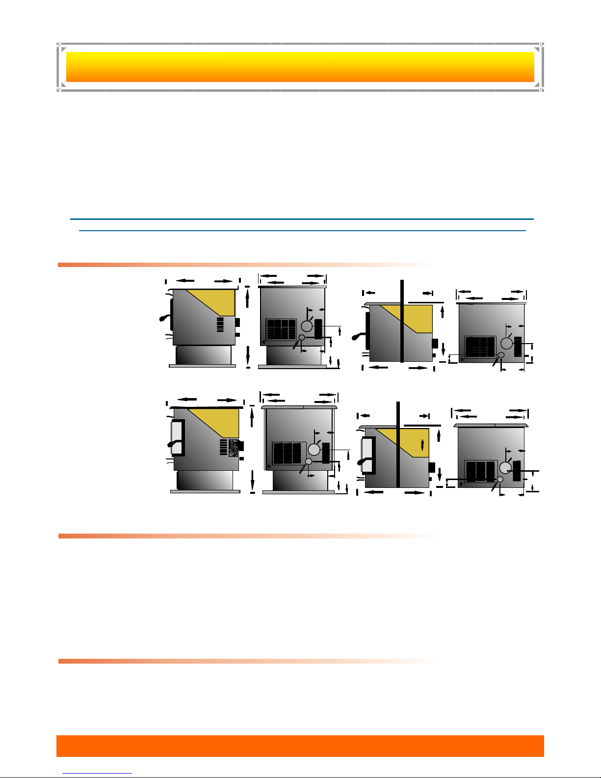
Bay View Freestanding
Bay View Insert / Built-In
Traditional Freestanding
Traditional Insert / Built-In
19‖
-
23‖
Adjus tab le
Hopp er
HEATING SPECIFICATIONS
S
PECIFICATIONS
S
PECIFICATIONS
Approx. Heating capacity (sq. feet) * 800 – 2,000
Approx. Fuel burn rate per hour ** 1.4 – 5.5 lbs
Hopper Capacity - Traditional Stove / Insert 40 lbs Approx. Burn time at lowest setting 27 hrs
Hopper Capacity – Bay View Free Standing 60 lbs Approx. Burn time at lowest setting 43 hrs
Hopper Capacity – Bay View Insert / Built-In 40-60 lbs Approx. Burn time at lowest setting 27-40
¹ Heating capacity will vary depending on floor plan layout of your home, degree of insulation, and
the outside temperature. Fuel size, quality, density and moisture level will also have an effect.
¹¹ Pellet size may affect the actual rate of fuel feed and burn times. Fuel feed rates may vary by as
much as 20%. Use PFI listed fuel for best results, pelletheat.org for further information.
DIMENSIONS
Product is subject to change without notice.
ELECTRICAL SPECIFICATIONS
Electrical Rating = 115 Volts 60 HZ 2.0 Amps
Watts (operational) = 175 (approximately)
Watts (optional igniter) = 475 (approximately)
A voltage surge protector or ground fault outlet is required for this unit. The warranty on the circuit
board will be voided if surge protection is not installed before operating this unit.
If power outages or disturbances are a concern, you may wish to purchase a gas powered generator,
solar or battery back-up system. Ensure that it is a ―Positive‖ sign wave and a minimum 1000 watts
continual, as well as surge protection.
EPA COMPLIANCE
This heater is exempt from EPA Phase II requirements, but has been tested for emissions using EPA test
methods by Warnock Hersey , US. Pellet appliances that are designed with the combustion air supply
exceeding 35:1 (by ratio) are exempt from EPA regulations.
PelPro Appliances www.pelprostoves.com 8
8

P
LANNING
P
LANNING
Unless you are knowledgeable and experienced in stove installation, we recommend your PelPro Appliance
receive a Pre-delivery Check and be installed by your local Specialty Retailer, NFI (National Fireplace Institute)
Pellet Specialist (USA) or WETT Certified Installer (CAN) .
& I
NSTALLATION
& I
NSTALLATION
C
C
HECK
HECK
L
L
IST
IST
COMPLETE THIS CHECK LIST PRIOR TO INSTALLING YOUR MULTI-FUEL APPLIANCE:
_____ Carefully read this "Owners Manual‖. SAVE THIS MANUAL.
_____ Have your local Dealer demonstrate all the operational, cleaning and maintenance steps
_____ Select a location. The design of your home and the stove placement will determine its value
Existing Chimneys, Pellet Fuel Storage, Aesthetic Considerations, Roof Design (rafter
_____ The installation of this appliance must conform to local codes and applicable state and
______ Attach your proof of purchase to this manual and keep on hand for warranty.
necessary for your stove.
as a source of heat. A pellet appliance depends primarily on air circulation to disperse its
heat. There are other practical considerations, which must be considered before a final
placement is decided on:
locations & roof pitch), Room Traffic, Clearances to Combustibles, and Existing Wiring.
federal requirements. Becoming familiar with these requirements before installation is es-
sential.
COMPLETE THIS CHECK LIST WHILE INSTALLING YOUR MULT—FUEL APPLIANCE:
_____ Carefully read the ENTIRE installation section first. Twice is better.
_____ Read the Installing Freestanding, Insert or Built-In sections.
_____ Determine the location and measurement needed your chosen location.
_____ Be sure to pre-fit all items before you install, fasten or install the stove permanently.
Remember measure twice, cut once.
_____ Ensure ALL joints of ―PL‖ vent and single wall stainless steel liner are tightly connected,
sealed with RTV Silicone or Hi-Temp foil tape, including to the exhaust connector, and
is correctly installed. (Follow vent manufacturer’s instructions.)
COMPLETE THIS CHECK LIST PRIOR TO LIGHTING YOUR FIRST FIRE:
_____ Obtain final inspection and approval by local building officials.
_____ Carefully clean all marks off the brass, nickel or pewter parts before the first fire is lit. Use a
soft cloth and a gentle type cleaner. Caution: Never use an abrasive cleaner on any part of your
_____ Polish the hopper to remove the oil type coating used in manufacturing.
_____ The high temp. stove paint used on your stove may take several hours of burning at a high fuel
_____ Review and follow the Lighting and Controls Instructions.
_____ Ensure that appliance is connected to a surge protection unit.
_____ Fill the hopper with quality pellets, Close the Hopper Lid Using the CCI ―AcuTron‖, (figure 5),
stove.
setting to fully cure. During this time an odor, which is not harmful, may be evident. The area
around the stove should be well ventilated.
PUSH the FEED RATE Touch Pad and this will start the auger and the combustion fan.
PelPro Appliances www.pelprostoves.com 9
9
P
1
2
3
4
5
6
7
8
9
LANNING
P
LANNING
PELLET VENT MUST MAINTAIN A MINIMUM 3‖ CLEARANCE TO ANY COMBUSTIBLE
(INSTALL VENT AT CLEARANCES SPECIFIED BY THE VENT MANUFACTURER).
DO NOT CONNECT THE PELLET VENT TO A VENT SERVING ANY OTHER APPLIANCE OR
DO NOT INSTALL A FLUE DAMPER IN THE EXHAUST VENTING SYSTEM OF THIS UNIT.
—EE
—
STOVE.
XHAUST
XHAUST
S
YSTEMS
S
YSTEMS
PELLET VENT TYPE:
1. Must be an approved 3‖ or 4‖ Diameter Type ‖PL‖ vent, vented to the outside (fig. 7) or connect
the vent to a factory built type ―A‖ chimney using an adaptor.
2. Exception: A single wall ―All Fuel‖ Stainless Steel chimney liner may be used inside a fireplace
or fireplace installations (fig. 8) .
3. Some venting manufactures do make ―PL‖ vent for use with wood pellet fuel only and another
type of ―PL‖ vent for corn or bio mass fuels. If in doubt, plan for the future and use the corn or
multi-fuel
4. Use 4‖ dia. vent if vent or liner height is over 15’ or if installation is over 3.000’ above sea level.
NOTE: 4‖ diameter vent may be used in all installations. If in doubt, use 4‖ dia. vent.
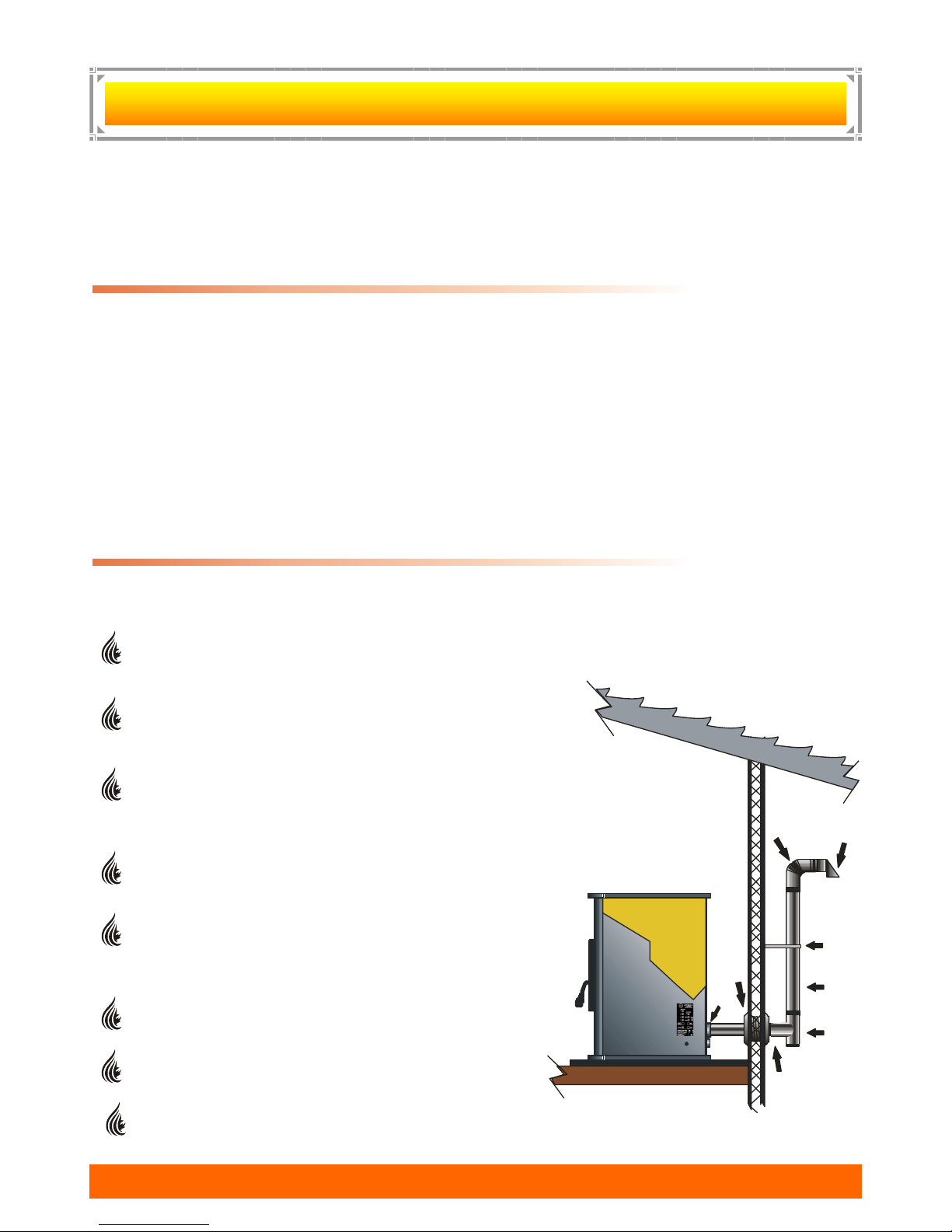
VENT SAFETY PRECAUTIONS:
A ―Clean Out Tee‖ (4) must be installed at the bottom of all vertical runs. These ―Tee’s‖ are to assist in
periodically cleaning the vent. Single or Double clean out tees may be used. The exhaust system must
be installed so the entire system can be cleaned without disassembly.
Termination must exhaust above the fresh air inlet
elevation, and parallel or above the exhaust output
of the multi-fuel appliance.
It is highly recommended that at least 3 feet of vertical
pipe (5) be installed to create some natural draft. This is
to help prevent the possibility of smoke or odor during
the appliance shut down.
Horizontal sections must have a 1/4‖ rise every 12‖ of
travel after 3’ long.
Pellet vent connections must be sealed gas tight. Use
Hi-Temp RTV Silicone, good for over 600° F or Hi-temp
Metal foil tape, that meets UL181 standards,. DO NOT
use ―Duct Tape‖.
Seal each vent section by injecting a liberal amount of
sealant into the gap and/or wrap with foil tape.
It is strongly recommended that the exhaust system
be terminated on the prevailing wind side of the home.
a gas fireplace.
Appliance may not be placed in, or vented through
PelPro Appliances www.pelprostoves.com 10
10
P
0 1 2 3 4 5 6 7 8 9 10
10
20
30
Altitude in Thousands of Fee t
E
q
u
i
v
a
l
e
n
t
P
i
p
e
L
e
n
g
t
h
i
n
F
e
e
t
3 or 4 Inc h Dia m e ter Pipe
4 Inch Diam e te r Only
Use Diameter ―PL‖ Vent
If venting outside of
shaded area.
4‖
0‘
0‘
5‘
5‘
10‘
10‘
15‘
20‘
25‘
30‘
33‘
Vent must have a support
bracket every 5’ when on
the exterior wall.
Vent height and run
exceed the distance
shown in the un-shaded
region of chart.
must
not
To achieve optimum
performance, keep vent runs
as short as possible.
Especially on horizontal
installations.
Use or Diameter
―PL‖ Vent, if venting in
shaded area.
3‖ 4‖
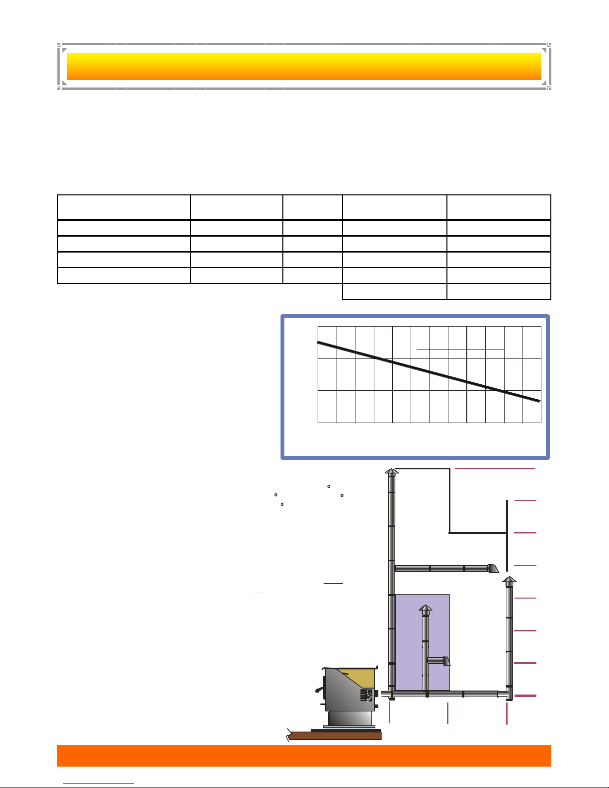
Maximum venting height is 33’.
Maximum horizontal offset is 10’.
Use the Equivalent Vent Length
Chart to determine proper
combination of component parts.
LANNING
P
LANNING
DETERMINE VENTING SIZE AND DISTANCE:
It is recommended that the vent system be installed with a minimum of three (3‘) of vertical
rise above the appliance exhaust port.
Equivalent Vent Length (EVL) is the method of determining vent sizes and lengths, that takes into account the
effect of different component parts on air flow.
STEP 1 To help you determine the correct size and/or run, simply fill in the chart below.
Pellet Venting
Component
90 Degree or Tee X 5
45 Degree X 3
Horizontal Pipe X 1
Vertical Pipe X .5
Total Equivalent
Step 2 Ensure the Total Equivalent
is or is less than 30.
Step 3 Use the Sizing Chart to
determine the proper venting
size according to the Total
Equivalent and the Altitude
above sea level.
NOTE: In some cases it may be
necessary to contact Hearth
& Home Technologies
Customer Service personal
to determine acceptable
venting configurations
and altitude adjustments
1-877-427-3316.
The diagram to the right will help to
give you a visual reference.
PelPro Appliances www.pelprostoves.com 11
— EE
—
# of Elbows
OR feet of Pipe
XHAUST
XHAUST
S
YSTEMS
S
YSTEMS
Multiply by Equivalent
…
CONTINUED
…
CONTINUED
Feet
Component
Equivalent
11
P
A
B
A
B
3‘
10‘
2‘
x
Inside Corner
Detail
I
E
LANNING
P
LANNING
— EE
—
XHAUST
XHAUST
S
YSTEMS
S
YSTEMS
…
CONTINUED
…
CONTINUED
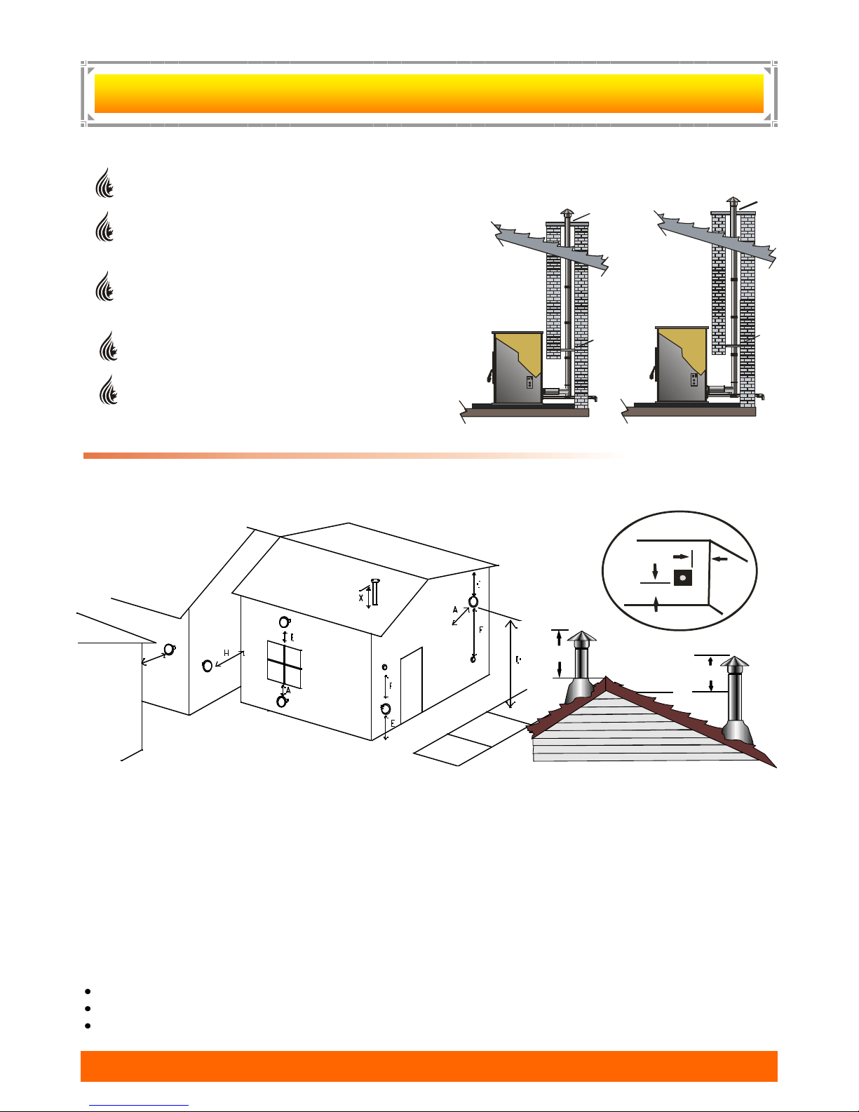
PELLET VENT TERMINATION: (Figures 7 & 8)
Termination must be a minimum of 12‖ above the chase cap (B) (note: the chimney must meet
local codes for height above the roof or other obstructions)
Must have an approved cap (G) (to prevent water
from entering) or a 45* elbow downturn (F)
If the termination is located on a windy side of
house, an approved house shield is recommended
to prevent soot from accumulating on the side of the
house.
Must not be located where snow or other materials
such as leafs, snow or grass, could block it.
Must have a ―Metal Seal Plate‖ or ―Wall Thimble‖ at
point (A)
Figure 7 Figure 8
VENT TERMINATION CLEARANCES:
NOTE: Horizontal terminations must protrude 12‖ from the wall, vertical terminations 24‖
A Minimum 4’ clearance below or beside any door or window which opens.
B Minimum 1’ clearance above any door or window that opens.
C Minimum 3’ clearance from any adjacent building.
D Minimum 7’ clearance above any grade when adjacent to public walkways.
E Minimum 2’ clearance above any grass, plants, or other combustible material.
Minimum 1’ clearance above grade.
F Minimum 3’ clearance above any forced air intake of any other appliance within 6’.
G Minimum 2’ clearance below eves or overhang.
H Minimum 1’ clearance horizontally from combustible wall.
I Minimum 1’ clearance to inside corner
X Must be a minimum of 36‖ above the roof and 24‖ above the highest point of the roof within 10’.
NOTE: The following are not found on the above diagram.
PelPro Appliances www.pelprostoves.com 12
Minimum 3’ above a gas meter/regulator within 3’ horizontally of the vertical centre line of regulator.
Minimum 6’ clearance to a gas service regulator vent outlet.
Minimum 1’ clearance under veranda, porch, deck or balcony. Permitted only if structure is fully open on
a minimum of two sides beneath the floor.
12
 Loading...