

Hearth & Home ECHEL36STIN-C, ECHEL36IN-C, ECHEL48IN-C, ECHEL60IN-C, ECHEL48STIN-C Installation Manual
...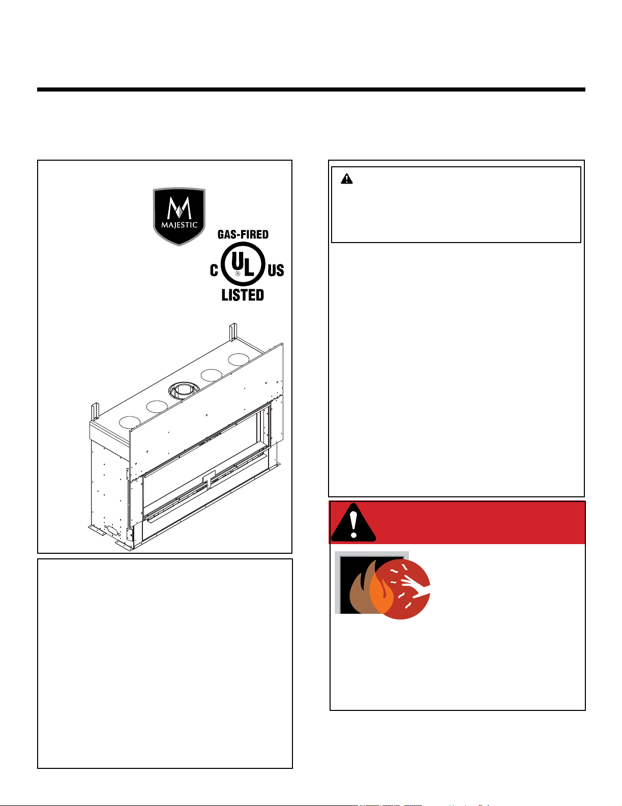
Installation Manual
Installation and Appliance Setup
CAUTION! Risk of Fire! DO NOT store instruction manuals inside replace cavity.
High temperatures could cause a re.
INSTALLER: Leave this manual with the appliance, not inside the appliance.
CONSUMER: Retain this manual for future reference. Do not store inside the appliance.
NOTICE: DO NOT discard this manual!
ECHELON-C
SERIES
Models:
ECHEL36IN-C
ECHEL36STIN-C
ECHEL48IN-C
ECHEL48STIN-C
ECHEL60IN-C
ECHEL72IN-C
WARNING:
FIRE OR EXPLOSION HAZARD
Failure to follow safety warnings exactly
could result in serious injury, death, or
property damage.
• DO NOT store or use gasoline or other am-
mable vapors and liquids in the vicinity of this
or any other appliance.
• What to do if you smell gas
- DO NOT try to light any appliance.
- DO NOT touch any electrical switch. DO
NOT use any phone in your building.
- Leave the building immediately.
- Immediately call your gas supplier from
a neighbor’s phone. Follow the gas supplier’s instructions.
- If you cannot reach your gas supplier, call
the re department.
• Installation and service must be performed
by a qualied installer, service agency, or the
gas supplier.
DANGER
HOT GLASS WILL
This appliance may be installed as an OEM
installation in manufactured home (USA
only) or mobile home and must be installed
in accordance with the manufacturer’s
instructions and the Manufactured Home
Construction and Safety Standard, Title 24
CFR, Part 3280 in the United States, or the
Standard for Installation in Mobile Homes,
CAN/CSA Z240 MH Series, in Canada.
This appliance is only for use with the type(s)
of gas indicated on the rating plate. This
appliance is not convertible for use with other
gases, unless a certied kit is used.
Majestic • ECHEL36IN-C/STIN-C, ECHEL48IN-C/STIN-C, ECHEL60IN-C, ECHEL72IN-C Installation Manual • 2608-980 Rev. D • 9/19
A barrier designed to reduce the risk of
burns from the hot viewing glass is provided
with this appliance and shall be installed for
the protection of children and other at-risk
individuals.
Decorative barrier front must be ordered separately at
time of appliance purchase. See Section 3.A.
NEVER ALLOW CHILDREN
CAUSE BURNS.
DO NOT TOUCH GLASS
UNTIL COOLED.
TO TOUCH GLASS.
1

Safety Alert Key:
• DANGER! Indicates a hazardous situation which, if not avoided will result in death or serious injury.
• WARNING! Indicates a hazardous situation which, if not avoided could result in death or serious injury.
• CAUTION! Indicates a hazardous situation which, if not avoided, could result in minor or moderate injury.
• NOTICE: Used to address practices not related to personal injury.
Table of Contents
Installation Standard Work Checklist ....................3
1 Product Specic and Important Safety Information
A. Appliance Certication ............................4
B. Glass Specications ..............................4
C. BTU Specications ............................... 4
D. High Altitude Installations .......................... 4
E. Non-Combustible Materials Specication. . . . . . . . . . . . . . 5
F. Combustible Materials Specication .................5
G. Electrical Codes .................................5
H. California ......................................5
I. Requirements for the Commonwealth of Massachusetts . . 6
2 Getting Started
A. Design and Installation Considerations ............... 7
B. Good Faith Wall Surface ..........................8
C. Tools and Supplies Needed ........................9
D. Inspect Appliance and Components ..................9
3 Framing and Clearances
A. Appliance/Decorative Barrier Front Dimension Diagrams 10
B. Appliance Location and Clearances to Combustibles ... 15
C. Constructing the Appliance Chase .................. 19
D. Floor Protection ................................ 20
7 Venting
A. Assemble Vent Sections (DVP Pipe Only) ...........40
B. Assemble Slip Sections ..........................42
C. Secure the Vent Sections .........................42
D. Disassemble Vent Sections ....................... 43
E. Vertical Termination Requirements ..................44
F. Horizontal Termination Requirements ...............45
8 Electrical Information
A. General Information .............................47
B. Wiring Requirements ............................49
9 Gas Information
A. Fuel Conversion ................................51
B. Gas Pressure .................................. 51
C. Gas Service Access .............................51
D. Gas Connection ................................ 53
E. High Altitude Installations .........................53
F. Air Shutter Setting .............................. 54
10 Finishing
A. Facing Material .................................55
B. Decorative Barrier Fronts .........................59
C. Mantel and Wall Projections .......................64
4 Termination Location and Vent Information
A. Approved Pipe .................................21
B. Vent Termination Minimum Clearances ..............21
C. Vent Terminal Clearances ........................22
D. Use of Elbows .................................23
E. Vent Diagrams .................................24
5 Vent Clearances and Vent Framing
A. Vent Clearances to Combustibles ..................33
B. Wall Penetration Framing/Firestops ................. 34
C. Ceiling Firestop/Floor Penetration Framing ........... 35
D. Install Attic Insulation Shield .......................35
6 Appliance Preparation
A. Top Standoff Preparation .........................36
B. Prepare For Heat Management ....................37
C. Securing and Leveling the Appliance ................ 38
D. Installing Non-Combustible Facing Material ..........39
11 Appliance Setup
A. Fixed Glass Assembly Removal and Replacement ..... 67
B. Remove the Shipping Materials/Install Bottom Glass
Shield ........................................67
C. Clean the Appliance .............................68
D. Install Glass Refractory (Optional) .................68
E. Install Log Set or Stones (Optional) ................ 68
F. Install Media (Included) .......................... 68
G. IntelliFire™ Touch Control System Setup ............. 71
12 Reference Materials
A. Vent Components Diagrams ......................72
B. Accessories ................................... 78
= Contains updated information.
Majestic • ECHEL36IN-C/STIN-C, ECHEL48IN-C/STIN-C, ECHEL60IN-C, ECHEL72IN-C Installation Manual • 2608-980 Rev. D • 9/192
Installation Standard Work Checklist
ATTENTION INSTALLER:
This standard work checklist is to be used by the installer in conjunction with, not instead of, the instructions contained in this
installation manual.
Customer:
Lot/Address:
(circle one): ECHEL36IN-C ECHEL36STIN-C ECHEL48IN-C
Model
ECHEL48STIN-C ECHEL60IN-C ECHEL72IN-C
WARNING! Risk of Fire or Explosion! Failure to install appliance according to these instructions can
lead to a re or explosion.
gies. Unapproved components and accessories could cause replace to overheat.
Appliance Install Sections 3 and 6 YES IF NO, WHY?
Veried that the chase is insulated and sealed. (Pg. 19) ___________________________
Required factory included non-combustible board is installed. (Pg 39) ___________________________
Standoffs bent up into installation position and secured. (Pg. 36) ___________________________
Veried clearances to combustibles. (Pg. 15-18) ___________________________
Fireplace is leveled and secured. (Pg. 38) ___________________________
Header no wider than 3.5 in.(2x4) (Pg. 17-18) _____________________________
Heat management system(s) and/or power vent properly installed. ___________________________
Venting/Chimney Sections 4,5 and 7
Venting conguration complies to vent diagrams. (Pg 24-32) ___________________________
Venting installed, locked, and secured in place with proper clearance. ___________________________
(May need to order separately.)
Firestops installed. (Section 5) ___________________________
Attic insulation shield installed. (Pg 35) ___________________________
Exterior wall/Roof ashing installed and sealed. (Section 7) ___________________________
Terminations installed and sealed. (Section 7) ___________________________
Follow this Standard Work Checklist
Date Installed:
Location of Fireplace:
Installer:
Dealer/Distributor Phone #
Serial #:
Install ONLY components and accessories approved by Hearth & Home Technolo-
Electrical Section 8 (Pg 47-50)
Unswitched power (110-120 VAC) provided to the appliance. ___________________________
Switch wires properly installed. ___________________________
Gas Section 9 (Pg 51-54)
Proper appliance for fuel type. ___________________________
Was a conversion performed? ___________________________
Leak check performed and inlet pressure veried. ___________________________
Veried proper air shutter setting for installation type. ___________________________
Finishing Section 10 (Pg 55-66)
Combustible materials not installed in non-combustible areas. ___________________________
Veried all clearances meet installation manual requirements. ___________________________
Finishing done correctly using inside t or overlap t method. ___________________________
Bottom nishing template and nishing guards removed. ___________________________
Mantels and wall projections comply with installation manual requirements. ___________________________
Appliance Setup Section 11 (Pg 67-71)
All packaging and protective materials removed (inside & outside of appliance). ___________________________
Refractories and media installed correctly. ___________________________
Glass assembly installed and secured. ___________________________
Accessories installed properly. ___________________________
Decorative barrier front properly installed. (May need to order separately.) ___________________________
Manual bag and all of its contents are removed from inside/under
the appliance and given to party responsible for use and operation. ___________________________
Started appliance and veried no gas leaks exist. ___________________________
Lights work in all switched positions (if so equipped). ___________________________
Component heat shield is installed. (Pg. 51.) ___________________________
Hearth & Home Technologies recommends the following:
• Photographing the installation and copying this checklist for your le.
• That this checklist remain visible at all times on the appliance until the installation is complete.
Comments: Further description of the issues, who is responsible (Installer/ Builder/ Other Trades, etc) and corrective
action needed _____________________________________________________________________________________
Comments Communicated to party responsible ____________________ by ______________________on ___________
(Builder / Gen. Contractor/) (Installer) (Date)
= Contains updated information.
2608-982 5/19
Majestic • ECHEL36IN-C/STIN-C, ECHEL48IN-C/STIN-C, ECHEL60IN-C, ECHEL72IN-C Installation Manual • 2608-980 Rev. D • 9/19
3
Product Specic and Important Safety Information
1
A. Appliance Certication
MODEL: ECHEL36IN-C ECHEL36STIN-C
ECHEL48IN-C ECHEL48STIN-C
ECHEL60IN-C ECHEL72IN-C
LABORATORY: Underwriters Laboratories, Inc. (UL)
TYPE: Direct Vent Heater
STANDARD: ANSI Z21.88-2017 • CSA 2.33-2017
This product is listed to ANSI standards for “Vented
Gas Fireplace Heaters” and applicable sections of “Gas
Burning Heating Appliances for Manufactured Homes
and Recreational Vehicles”, and “Gas Fired Appliances
for Use at High Altitudes”. Also Certied for Installation in
a Bedroom or a Bedsitting Room.
NOTICE: This installation must conform with local codes.
In the absence of local codes you must comply with the
National Fuel Gas Code, ANSI Z223.1-latest edition in
the U.S.A. and the CAN/CGA B149 Installation Codes in
Canada.
NOT INTENDED FOR USE AS A PRIMARY HEAT SOURCE.
This appliance is tested and approved as either supplemental room heat or as a decorative appliance. It should not be
factored as primary heat in residential heating calculations.
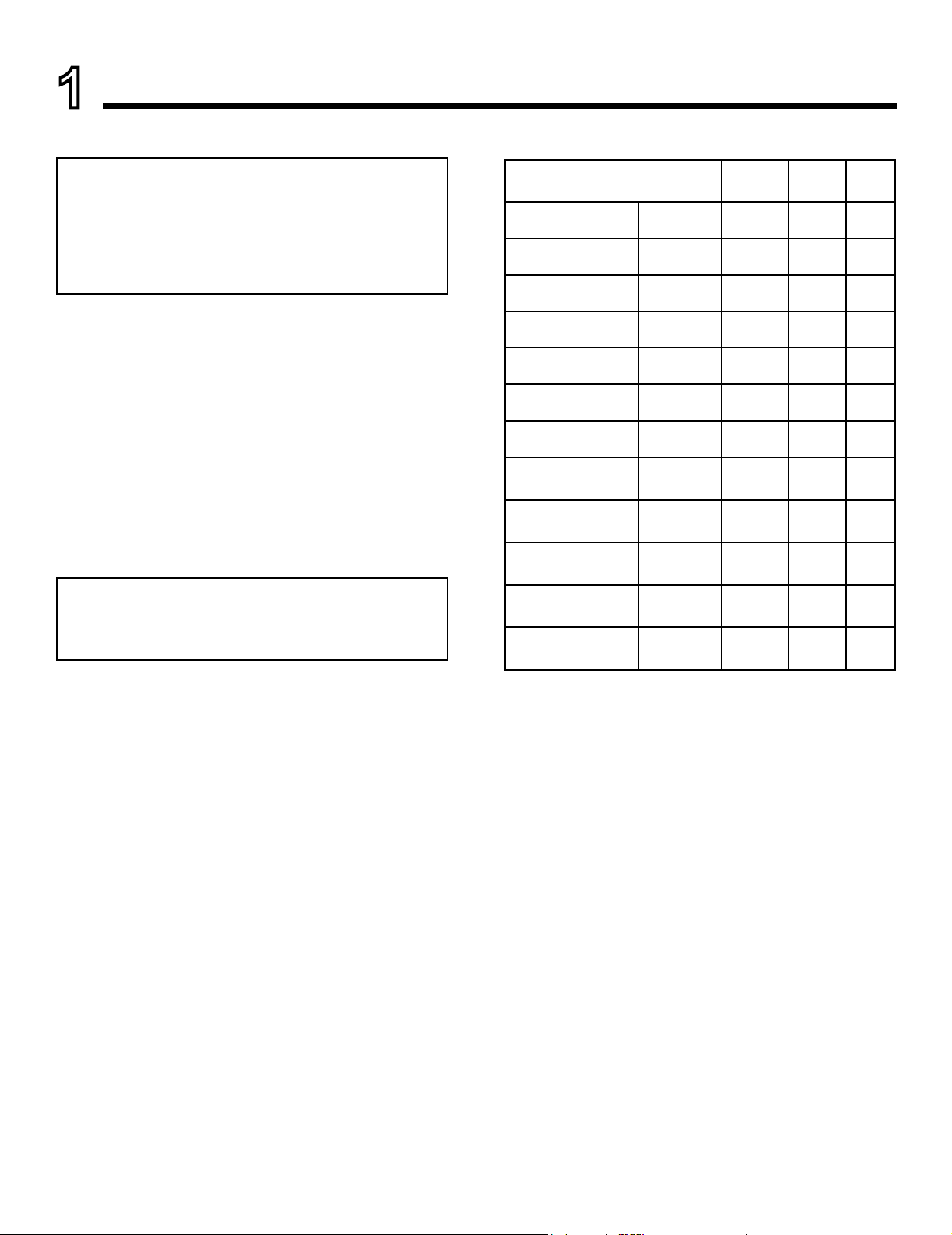
C. BTU Specications
Models
(U.S. or Canada)
ECHEL36IN-C
(NG)
ECHEL36IN-C
(Propane)
ECHEL36STIN-C
(NG)
ECHEL36STIN-C
(Propane)
ECHEL48IN-C
(NG)
ECHEL48IN-C
(Propane)
ECHEL48STIN-C
(NG)
ECHEL48STIN-C
(Propane)
ECHEL60IN-C
(NG)
ECHEL60IN-C
(Propane)
ECHEL72IN-C
(NG)
ECHEL72IN-C
(Propane)
(0-2000 FT) 30,000 17,500 #36
(0-2000 FT) 27,000 15,000 #52
(0-2000 FT) 30,000 17,500 #36
(0-2000 FT) 27,000 15,000 #52
(0-2000 FT) 40,000 21,000 .124
(0-2000 FT) 34,000 20,000 #50
(0-2000 FT) 40,000 21,000 .124
(0-2000 FT) 34,000 20,000 #50
(0-2000 FT) 50,000 28,000 #28
(0-2000 FT) 37,500 20,000 #49
(0-2000 FT) 58,000 30,000 #23
(0-2000 FT) 45,000 25,000 #46
Maximum
Input BTU/h
Minimum
Input
BTU/h
Orice
Size
(DMS)
B. Glass Specications
This appliance is equipped with 5 mm ceramic glass. Replace glass only with 5 mm ceramic glass. Please contact
your dealer for replacement glass.
D. High Altitude Installations
NOTICE: If the heating value of the gas has been reduced,
these rules do not apply. Check with your local gas utility
or authorities having jurisdiction.
When installing above 2000 feet elevation:
• In the USA: Reduce input rate 4% for each 1000 feet
above 2000 feet.
• In CANADA: Input ratings are certied without a
reduction of input rate for elevations up to 4500 feet
(1370 m) above sea level. Please consult provincial
and/or local authorities having jurisdiction for
installations at elevations above 4500 feet (1370 m).
Check with your local gas utility to determine proper
orice size.
Majestic • ECHEL36IN-C/STIN-C, ECHEL48IN-C/STIN-C, ECHEL60IN-C, ECHEL72IN-C Installation Manual • 2608-980 Rev. D • 9/194
E. Non-Combustible Materials Specication
Material which will not ignite and burn. Such materials are
those consisting entirely of steel, iron, brick, tile, concrete,
slate, glass or plasters, or any combination thereof.
Materials that are reported as passing ASTM E 136,
Standard Test Method for Behavior of Materials in
a Vertical Tube Furnace at 750 ºC shall be considered
non-combustible materials.
F. Combustible Materials Specication
Materials made of or surfaced with wood, compressed paper, plant bers, plastics, or other material that can ignite
and burn, whether ame proofed or not, or plastered or
unplastered shall be considered combustible materials.
G. Electrical Codes
NOTICE: This appliance must be electrically wired
and grounded in accordance with local codes or, in the
absence of local codes, with National Electric Code
ANSI/NFPA 70-latest edition or the Canadian Electric
Code CSA C22.1.
• A 110-120 VAC circuit for this product must be pro-
tected with ground-fault circuit interrupter protection,
in compliance with the applicable electrical codes,
when it is installed in locations such as in bathrooms
or near sinks.
H. California
WARNING: This product and the fuels used to
operate this product (liquid propane or natural
gas), and the products of combustion of such fuels, can
expose you to chemicals including benzene, which is
known to the State of California to cause cancer and
reproductive harm. For more information go to: www.
P65Warnings.ca.gov.
Majestic • ECHEL36IN-C/STIN-C, ECHEL48IN-C/STIN-C, ECHEL60IN-C, ECHEL72IN-C Installation Manual • 2608-980 Rev. D • 9/19
5

Note: The following requirements reference various
Massachusetts and national codes not contained in this
document.
I. Requirements for the Commonwealth of
Massachusetts
For all side wall horizontally vented gas fueled equipment
installed in every dwelling, building or structure used in
whole or in part for residential purposes, including those
owned or operated by the Commonwealth and where the
side wall exhaust vent termination is less than seven (7)
feet above nished grade in the area of the venting, including but not limited to decks and porches, the following
requirements shall be satised:
Installation of Carbon Monoxide Detectors
At the time of installation of the side wall horizontal vented
gas fueled equipment, the installing plumber or gas tter
shall observe that a hard wired carbon monoxide detector
with an alarm and battery back-up is installed on the oor
level where the gas equipment is to be installed. In addition, the installing plumber or gas tter shall observe that
a battery operated or hard wired carbon monoxide detector with an alarm is installed on each additional level of
the dwelling, building or structure served by the side wall
horizontal vented gas fueled equipment. It shall be the
responsibility of the property owner to secure the services
of qualied licensed professionals for the installation of
hard wired carbon monoxide detectors.
In the event that the side wall horizontally vented gas fueled equipment is installed in a crawl space or an attic,
the hard wired carbon monoxide detector with alarm and
battery back-up may be installed on the next adjacent
oor level.
In the event that the requirements of this subdivision can
not be met at the time of completion of installation, the
owner shall have a period of thirty (30) days to comply
with the above requirements; provided, however, that during said thirty (30) day period, a battery operated carbon
monoxide detector with an alarm shall be installed.
Inspection
The state or local gas inspector of the side wall horizontally vented gas fueled equipment shall not approve the
installation unless, upon inspection, the inspector observes carbon monoxide detectors and signage installed
in accordance with the provisions of 248 CMR 5.08(2)(a)1
through 4.
Exemptions
The following equipment is exempt from 248 CMR 5.08(2)
(a)1 through 4:
• The equipment listed in Chapter 10 entitled “Equipment
Not Required To Be Vented” in the most current edition
of NFPA 54 as adopted by the Board; and
• Product Approved side wall horizontally vented gas fueled equipment installed in a room or structure separate
from the dwelling, building or structure used in whole or
in part for residential purposes.
MANUFACTURER REQUIREMENTS
Gas Equipment Venting System Provided
When the manufacturer of Product Approved side wall
horizontally vented gas equipment provides a venting
system design or venting system components with the
equipment, the instructions provided by the manufacturer
for installation of the equipment and the venting system
shall include:
• Detailed instructions for the installation of the venting
system design or the venting system components; and
• A complete parts list for the venting system design or
venting system.
Gas Equipment Venting System NOT Provided
When the manufacturer of a Product Approved side wall
horizontally vented gas fueled equipment does not provide the parts for venting the ue gases, but identies
“special venting systems”, the following requirements
shall be satised by the manufacturer:
Approved Carbon Monoxide Detectors
Each carbon monoxide detector as required in accordance with the above provisions shall comply with NFPA
720 and be ANSI/UL 2034 listed and IAS certied.
Signage
A metal or plastic identication plate shall be permanently mounted to the exterior of the building at a minimum
height of eight (8) feet above grade directly in line with the
exhaust vent terminal for the horizontally vented gas fueled heating appliance or equipment. The sign shall read,
in print size no less than one-half (1/2) in. in size, “GAS
VENT DIRECTLY BELOW. KEEP CLEAR OF ALL OBSTRUCTIONS”.
Majestic • ECHEL36IN-C/STIN-C, ECHEL48IN-C/STIN-C, ECHEL60IN-C, ECHEL72IN-C Installation Manual • 2608-980 Rev. D • 9/196
• The referenced “special venting system” instructions
shall be included with the appliance or equipment installation instructions; and
• The “special venting systems” shall be Product Approved by the Board, and the instructions for that system shall include a parts list and detailed installation
instructions.
A copy of all installation instructions for all Product Approved side wall horizontally vented gas fueled equipment, all venting instructions, all parts lists for venting
instructions, and/or all venting design instructions shall
remain with the appliance or equipment at the completion
of the installation.
See Gas Connection section for additional Commonwealth of Massachusetts requirements.
2
Getting Started
A. Design and Installation Considerations
WARNING! Risk of Fire or Explosion! Read all instructions before starting the installation.
Majestic direct vent gas appliances are designed to operate with all combustion air siphoned from outside of the
building and all exhaust gases expelled to the outside. No
additional outside air source is required.
Installation MUST comply with local, regional, state and
national codes and regulations. Consult insurance carrier,
local building inspector, re ofcials or authorities having
jurisdiction over restrictions, installation inspection and
permits.
Before installing, determine the following:
• Where the appliance is to be installed.
• The vent system conguration to be used. If Passive
Heat will be installed, consider location of discharge
opening in relation to venting and other construction
materials.
• Gas supply piping requirements.
• Provisions for optional heat management system(s).
• Electrical wiring requirements.
• Framing and nishing details.
• Whether optional accessories—devices such as a fan,
wall switch, or remote control—are desired.
Installation and service of this
appliance should be performed
by qualied personnel. Hearth &
Home Technologies recommends
NFI certied professionals.
Improper installation, adjustment, alteration, service or
maintenance can cause injury or property damage. For
assistance or additional information, consult a qualied
service technician, service agency or your dealer.
Majestic • ECHEL36IN-C/STIN-C, ECHEL48IN-C/STIN-C, ECHEL60IN-C, ECHEL72IN-C Installation Manual • 2608-980 Rev. D • 9/19
7
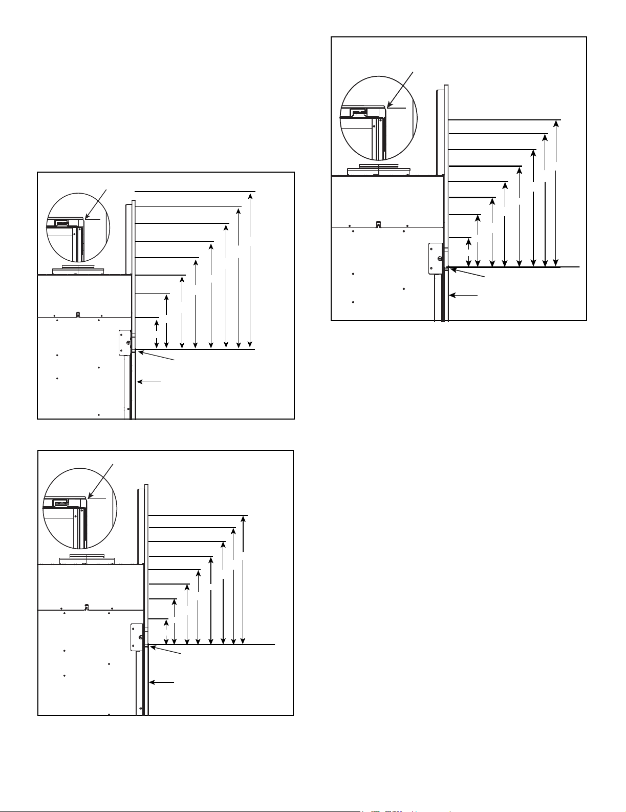
B. Good Faith Wall Surface
The ECHELON-C models may be installed with or without
optional heat management systems, including the Passive Heat kit. The installation of a heat management system will affect certain aspects of the appliance installation
including framing dimensions and clearances to combustibles. Note that Figure 2.3 in this section refers to the
wall surface temperatures when the Passive Heat kit is
installed.
FIREPL ACE
OPENI NG
130°F
140°F
145°F
155°F
170°F
6 in.
FACTORY-SUPPLIED NON-COMBUSTI BLE
BOARD SHOWN INSTALLED.
24 in.
18 in.
12 in.
MEASUREMENTS FROM
TOP EDGE O F THE FIREPLACE
OPENING
APPLIANCE FRONT
Figure 2.1 Good Faith Wall Surface Temperatures Above Appliance
(ECHEL36IN-C/ECHEL36STIN-C, ECHEL48IN-C, ECHEL48STIN-C)
FIREPL ACE
OPENIN G
140°F
155°F
190°F
24 in.
18 in.
245°F
12 in.
6 in.
135°F
TO CEILI NG
125°F
125°F
48 in.
42 in.
36 in.
30 in.
TO CEILING
125°F
125°F
48 in.
42 in.
36 in.
30 in.
OPTIONAL PASSIVE HEAT KIT INSTALLED
FIREPL ACE
OPENI NG
95°F
95°F
95°F
95°F
105°F
115°F
120°F
144°F
12 in.
6 in.
TOP EDGE O F THE OPENI NG
APPLIANCE FRONT
FACTORY-SUPPLIED NON-COMBUSTI BLE
BOARD SHOWN INSTALLED.
30 in.
24 in.
18 in.
MEASUREM ENTS FROM
Figure 2.3 Good Faith Wall Surface Temperatures Above Appliance
with Passive Heat Kit Installed
If installing a television (TV) above the appliance, see
Section 3 of the appliance Owner’s Manual.
NOTICE: Surface temperatures listed above are taken with
a temperature measuring probe as prescribed by the test
standard used for appliance certication. Temperatures
on walls or mantels taken with an infrared thermometer
may yield increased temperatures of up to 30 °F (17 °C) or
more depending on the thermometer settings and material
characteristics being measured. Use appropriate nishing
materials that are able to withstand these conditions. For
additional nishing guidelines, see Section 10.
48 in.
42 in.
36 in.
MEASUREME NTS FROM
TOP EDGE O F THE OPENING
APPLIANCE FRONT
FACTORY-SUPPLIED NON-COMBUSTI BLE
BOARD SHOWN INSTALLED.
Figure 2.2 Good Faith Wall Surface Temperatures Above Appliance
(ECHEL60IN-C, ECHEL72IN-C)
Majestic • ECHEL36IN-C/STIN-C, ECHEL48IN-C/STIN-C, ECHEL60IN-C, ECHEL72IN-C Installation Manual • 2608-980 Rev. D • 9/198

C. Tools and Supplies Needed
Before beginning the installation be sure that the following
tools and building supplies are available.
Hand Tools Tape measure
Level Framing material
Manometer Framing square
Voltmeter Electric drill and bits (1/4 in.)
Plumb line Safety glasses/Gloves
Wrenches Reciprocating saw
1/4 in. nut driver
Non-corrosive leak check solution
1/2 - 3/4 in. length, #6 or #8 Self-drilling screws
Caulking material (300 ºF minimum continuous exposure
rating)
D. Inspect Appliance and Components
WARNING! Risk of Fire or Explosion! Damaged parts
could impair safe operation. DO NOT install damaged, in-
complete or substitute components. Keep appliance dry.
WARNING! Risk of Fire, Explosion or Electric Shock!
DO NOT use this appliance if any part has been under
water. Call a qualied service technician to inspect the
appliance and to replace any part of the control system
and/or gas control which has been under water.
• Carefully remove the appliance and components from
the packaging.
• The vent system components and decorative barrier
fronts may be shipped in separate packages.
• If packaged separately, the media, refractory, and/or
optional log kits must be installed.
• Report to your dealer any parts damaged in shipment,
particularly the condition of the glass.
• This product is factory-equipped with an IntelliFire™
Touch remote control, which was paired to the appliance
at the factory. This specic remote control needs to
remain with the contents of the manual bag. Do not
install batteries in the remote control until performing the
nal appliance setup and checklist.
Hearth & Home Technologies disclaims any responsibility for,
and the warranty will be voided by, the following actions:
• Installation and use of any damaged appliance or vent
system component.
• Modication of the appliance or vent system.
• Installation other than as instructed by Hearth & Home
Technologies.
• Improper positioning of the logs/media (as applicable) or
the glass assembly.
• Installation and/or use of any component part not approved
by Hearth & Home Technologies.
Majestic • ECHEL36IN-C/STIN-C, ECHEL48IN-C/STIN-C, ECHEL60IN-C, ECHEL72IN-C Installation Manual • 2608-980 Rev. D • 9/19
9
Framing and Clearances
3
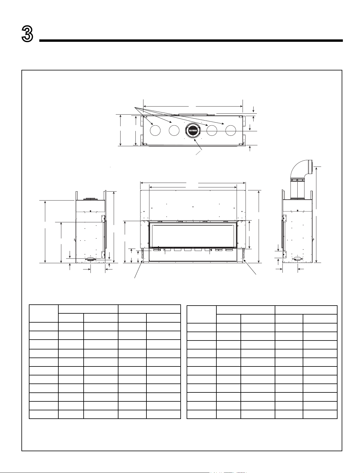
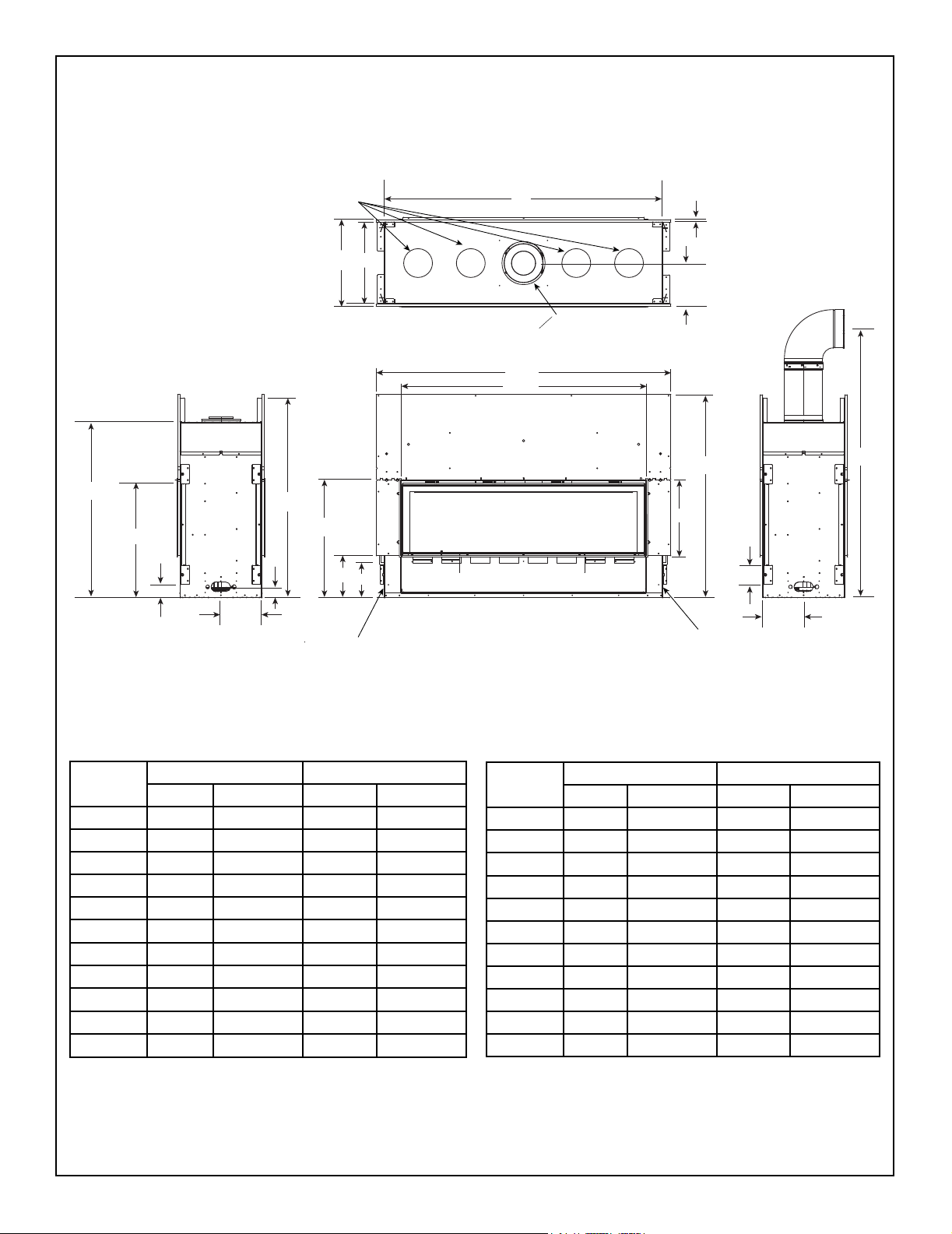
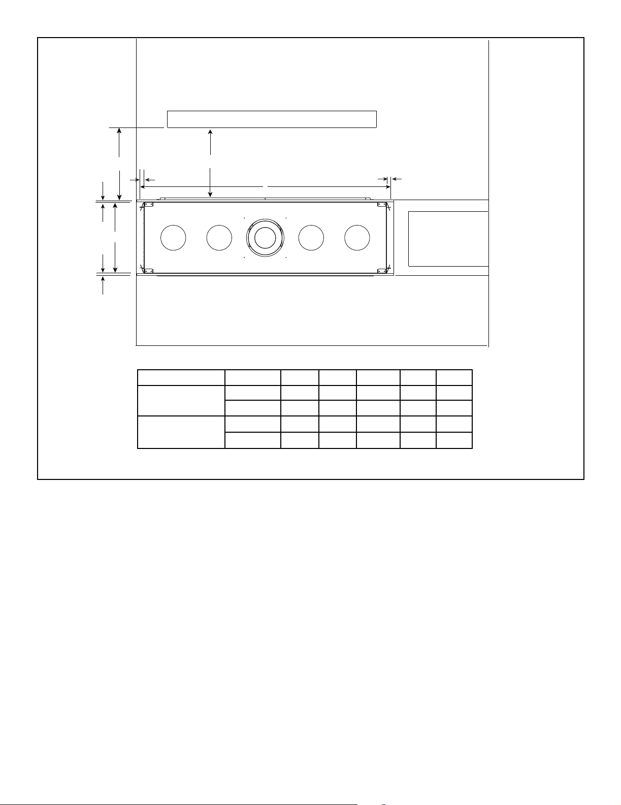
A. Appliance/Decorative Barrier Front Dimension Diagrams
Dimensions are actual appliance dimensions. Use for reference only. For framing dimensions and clearances refer to Section 5.
HEAT MANAGEMENT SYSTEMS KNOCKOUTS
IMPORTANT: Must use appropriate
knockout(s) for the selected Heat
Management System. See Section 6.
K
M
J
o
L
CENTERED ON APPLIANCE
A
B
I
H
V
U
T
Location
A 49-1/2 1257 61-1/2 1562
B 39-1/4 997 51-1/8 1299
C 15-5/8 397 15-5/8 397
D 42-1/2 1080 42-1/2 1080
E 4 102 4 102
F 8-9/16 218 8-9/16 218
G 63 1600 63 1600
H 8-9/16 218 8-9/16 218
I 1 25 1 25
J 46-3/16 1173 58 1473
K 17-1/8 435 17-1/8 435
ECHEL36IN-C ECHEL48IN-C
Inches Millimeters Inches Millimeters
N
Q
O
S
R
P
GAS ACCESS
D
C
E
F
ELECTRICAL ACCESS
Location
L 8 203 8 203
M 18-5/8 473 18-5/8 473
N 41-3/4 1061 41-3/4 1061
O 2-3/8 60 2-3/8 60
P 8-9/16 218 8-9/16 218
Q 24-1/2 622 24-1/2 622
R 7-1/4 184 7-1/4 184
S 8-7/8 225 8-7/8 225
T 2-3/4 70 2-3/4 70
U 23-3/4 603 23-3/4 603
V 36-5/8 930 36-5/8 930
ECHEL36IN-C ECHEL48IN-C
Inches Millimeters Inches Millimeters
G
Figure 3.1 Appliance Dimensions - ECHEL36IN-C, ECHEL48IN-C
Majestic • ECHEL36IN-C/STIN-C, ECHEL48IN-C/STIN-C, ECHEL60IN-C, ECHEL72IN-C Installation Manual • 2608-980 Rev. D • 9/1910
HEAT MANAGEMENT SYSTEMS KNOCKOUTS
IMPORTANT: Must use appropriate
knockout(s) for the selected Heat
Management System. See Section 6.
M
K
V
N
U
T
O
J
o
L
CENTERED ON APPLIANCE
A
B
I
H
G
D
C
Q
S
R
E
P
GAS ACCESS
Location
ECHEL60IN-C ECHEL72IN-C
Inches Millimeters Inches Millimeters
A 74 1880 86 2184
B 63-1/8 1603 75-1/8 1908
C 15-5/8 397 15-5/8 397
D 48-1/2 1232 48-1/2 1232
E 4 102 4 102
F 8-9/16 218 8-9/16 218
G 63 1600 75 1905
H 8-9/16 218 8-9/16 218
I 1 25 1 25
J 70 1778 82 2083
K 17-1/8 435 17-1/8 435
ELECTRICAL ACCESS
F
Location
L 8 203 8 203
M 18-5/8 473 18-5/8 473
N 47-3/4 1213 47-3/4 1213
O 2-3/8 60 2-3/8 60
P 8-9/16 218 8-9/16 218
Q 24-1/2 622 24-1/2 622
R 7-1/4 184 N/A N/A
S 8-7/8 225 8-7/8 225
T 2-3/4 70 2-3/4 70
U 23-3/4 603 23-3/4 603
V 36-1/2 927 36-1/2 927
ECHEL60IN-C ECHEL72IN-C
Inches Millimeters Inches Millimeters
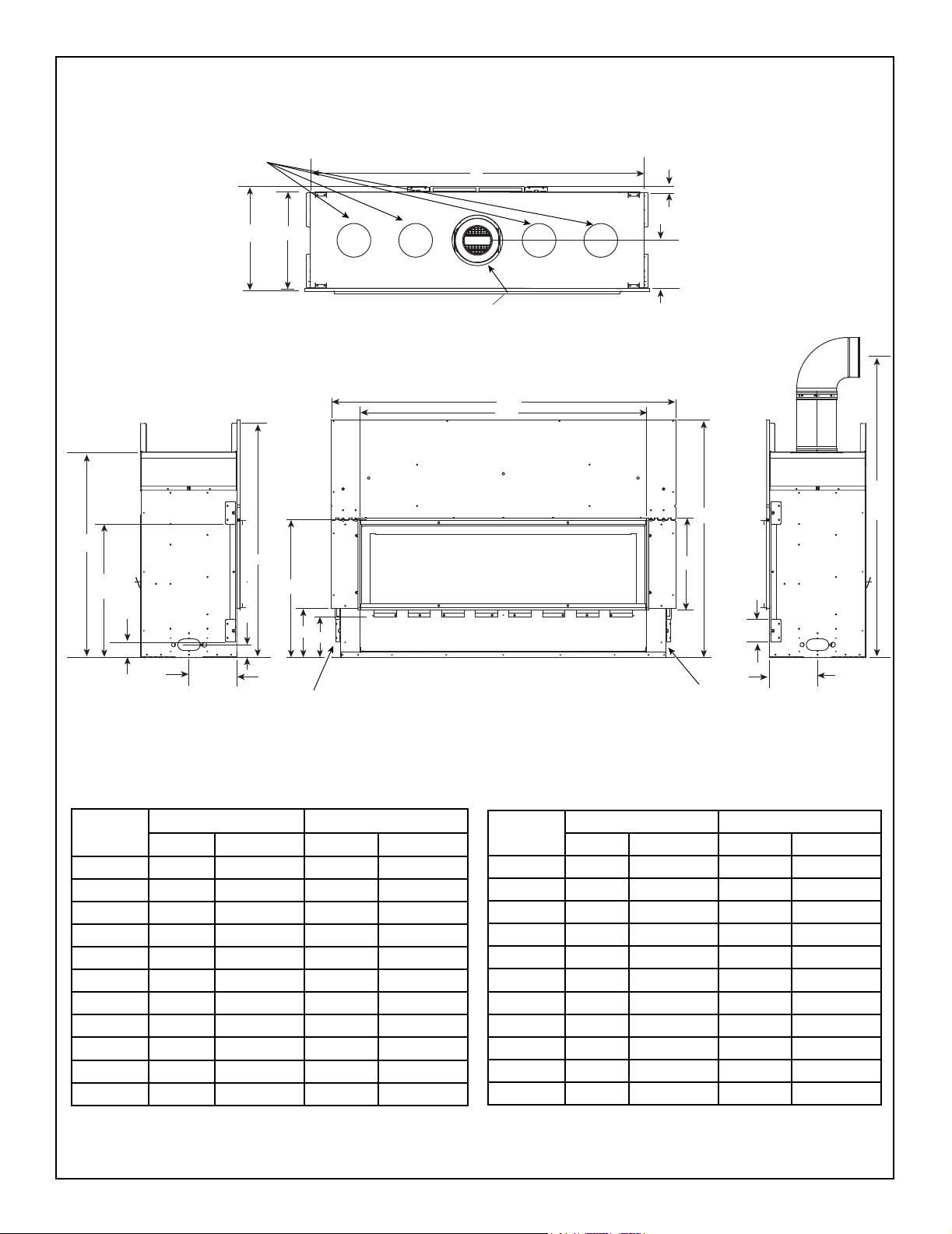
Figure 3.2 Appliance Dimensions - ECHEL60IN-C, ECHEL72IN-C
Majestic • ECHEL36IN-C/STIN-C, ECHEL48IN-C/STIN-C, ECHEL60IN-C, ECHEL72IN-C Installation Manual • 2608-980 Rev. D • 9/19
11
HEAT MANAGEMENT SYSTEMS KNOCKOUTS
IMPORTANT: Must use appropriate
knockout(s) for the selected Heat
Management System. See Section 6.
K
M
J
o
L
CENTERED ON APPLIANCE
A
B
I
H
V
Location
U
T
ECHEL36STIN-C ECHEL48STIN-C
Inches Millimeters Inches Millimeters
N
Q
O
S
R
P
GAS ACCESS
A 50 1270 62 1575
B 39-1/4 997 51-1/8 1299
C 15-5/8 397 15-5/8 397
D 42-1/2 1080 42-1/2 1080
E 4 102 4 102
F 8-9/16 218 8-9/16 218
G 63 1600 63 1600
H 8-9/16 218 8-9/16 218
I 1/2 13 1/2 13
J 46-3/16 1173 58 1473
K 17-1/8 435 17-1/8 435
D
C
E
F
ELECTRICAL ACCESS
Location
L 8 203 8 203
M 18-1/8 460 18-1/8 460
N 41-3/4 1061 41-3/4 1061
O 2-3/8 60 2-3/8 60
P 8-9/16 218 8-9/16 218
Q 24-1/2 622 24-1/2 622
R 7-1/4 184 7-1/4 184
S 8-7/8 225 8-7/8 225
T 2-3/4 70 2-3/4 70
U 23-3/4 603 23-3/4 603
V 36-1/2 927 36-1/2 927
ECHEL36STIN-C ECHEL48STIN-C
Inches Millimeters Inches Millimeters
G
Figure 3.3 Appliance Dimensions - ECHEL36STIN-C, ECHEL48STIN-C
Majestic • ECHEL36IN-C/STIN-C, ECHEL48IN-C/STIN-C, ECHEL60IN-C, ECHEL72IN-C Installation Manual • 2608-980 Rev. D • 9/1912
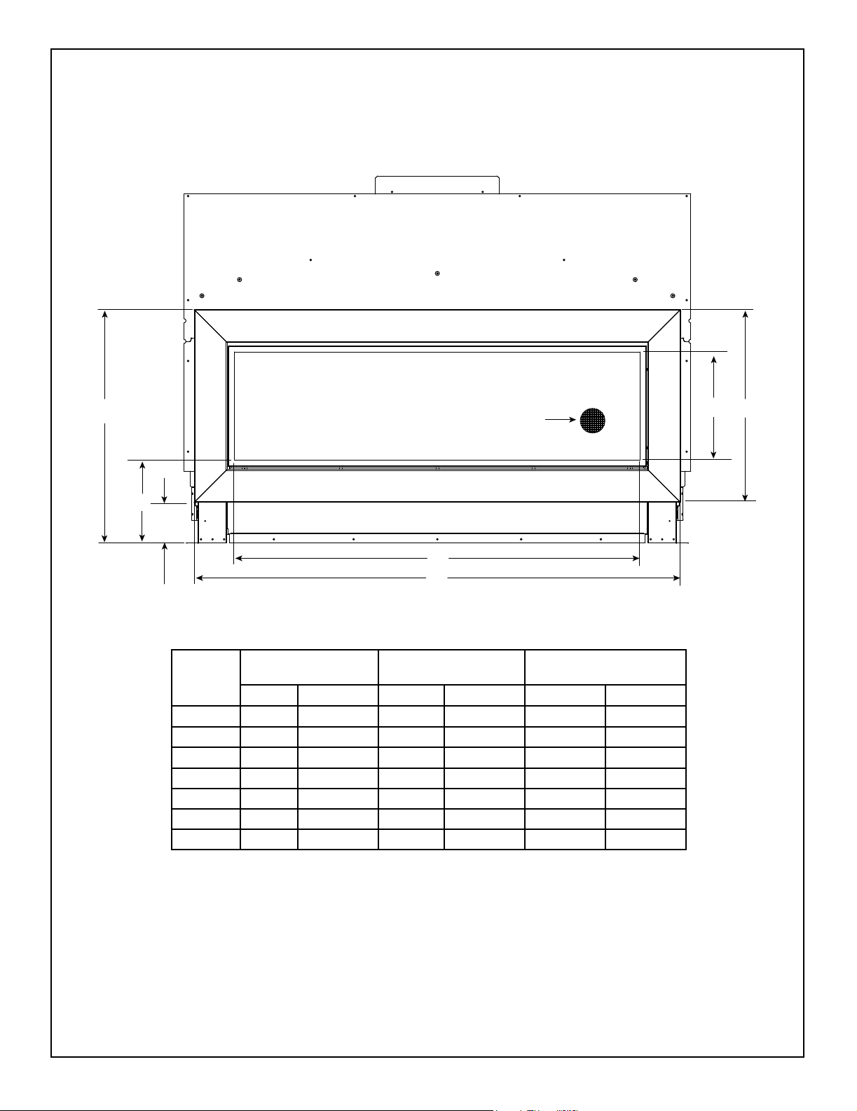
PFF DECORATIVE FRONT
G
Note: See Section 10 for hearth, mantel
and nishing requirements.
Barrier Mesh: Integral to
Decorative Barrier Front
F
B
E
D
A
C
ECHEL36IN-C
Location
A 37-1/4 946 49-1/4 1250 61-1/4 1556
B 13-1/8 333 13-1/8 333 13-1/8 333
C 47 1194 59 1498 71 1803
D 4-15/16 126 4-15/16 126 4-15/16 126
E 10-1/16 256 10-1/16 256 10-1/16 256
F 23-3/8 594 23-3/8 594 23-3/8 594
G 28-5/16 719 28-5/16 719 28-5/16 719
ECHEL36STIN-C
Inches Millimeters Inches Millimeters Inches Millimeters
ECHEL48IN-C
ECHEL48STIN-C
ECHEL60IN-C
The PFF decorative front has an installed depth of 3/4 in. (19 mm), measured from the
front of the non-combustible nishing material to the front of the decorative front.
Figure 3.4 Picture Frame Front Dimensions
Majestic • ECHEL36IN-C/STIN-C, ECHEL48IN-C/STIN-C, ECHEL60IN-C, ECHEL72IN-C Installation Manual • 2608-980 Rev. D • 9/19
13
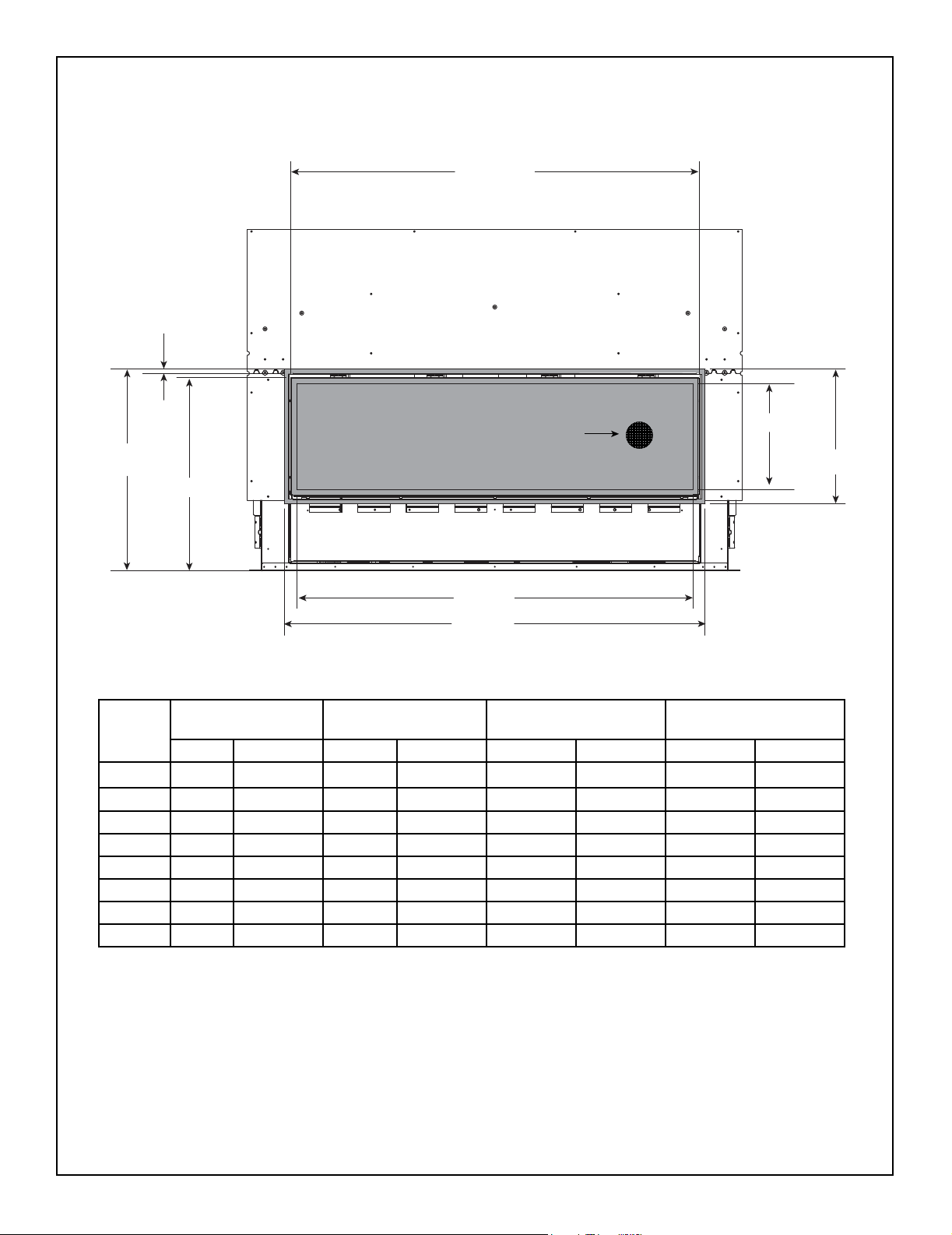
CLEAN FACE TRIM DECORATIVE BARRIER FRONT
E
A
G
Note: See Section 10 for
hearth, mantel and nishing
requirements.
Barrier Mesh: Integral to
Decorative Barrier Front
H
F
D
ECHEL36IN-C
Location
A 39 991 51 1295 63 1600 75 1905
B 16-3/4 425 16-3/4 425 16-3/4 425 16-3/4 425
C 13-1/8 333 13-1/8 333 13-1/8 333 13-1/8 333
D 37-3/16 945 49-3/16 1249 61-3/16 1554 73-3/16 1859
E 40-5/16 1024 52-5/16 1329 64-5/16 1634 76-5/16 1938
F 24 610 24 610 24 610 24 610
G 5/8 16 5/8 16 5/8 16 5/8 16
H 25 635 25 635 25 635 25 635
ECHEL36STIN-C
Inches Millimeters Inches Millimeters Inches Millimeters Inches Millimeters
ECHEL48IN-C
ECHEL48STIN-C
ECHEL60IN-C ECHEL72IN-C
C
B
Figure 3.5 Clean Face Trim Front (Inside Fit) Decorative Barrier Front Dimensions
Majestic • ECHEL36IN-C/STIN-C, ECHEL48IN-C/STIN-C, ECHEL60IN-C, ECHEL72IN-C Installation Manual • 2608-980 Rev. D • 9/1914
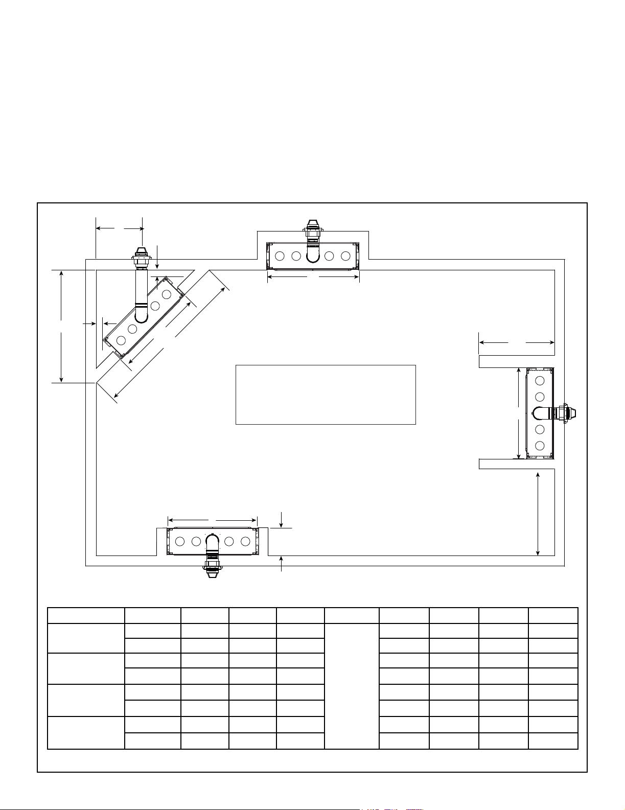
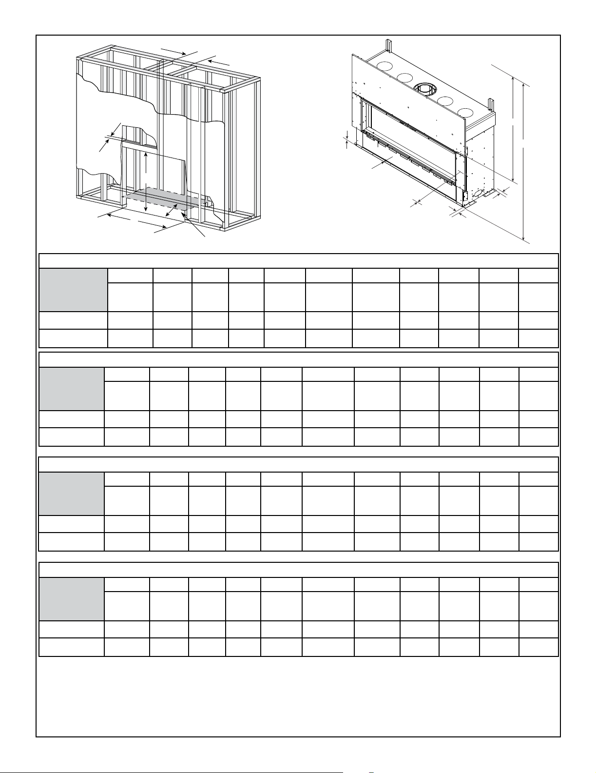
B. Appliance Location and Clearances to
Combustibles
When selecting a location for the appliance it is important
to consider the required clearances to walls and allow sufcient clearance for heat management systems venting.
See Figure 3.6 and Figure 3.7.
WARNING! Risk of Fire or Burns! Provide adequate
clearance around air openings and for service access.
Due to high temperatures, the appliance should be located
out of trafc and away from furniture and draperies.
E
G
G
A
B
C
NOTICE: Illustrations reect typical installations and are
FOR DESIGN PURPOSES ONLY. Illustrations/diagrams
are not drawn to scale. Actual installation may vary due to
individual design preference.
B
D
Refer to Section 10 for hearth, mantel and
wall projection information.
If a Heat Management System will be
installed, refer to Section 6.B for information.
18 in. (457 mm) required when Passive Heat Side
B
F
Discharge Kit is installed. Refer to the Passive
Heat kit instructions for more information.
H
Model A B C D E F G H
ECHEL36IN-C
ECHEL48IN-C
ECHEL60IN-C
ECHEL72IN-C
Inches 62-1/2 48-1/4 88-1/8
Millimeters 1588 1226 2238 622 476 25 1270
Inches 70-3/4 60-1/4 100-3/8 28-1/2 18-3/4 1 62
Millimeters 1797 1530 2550 724 476 25 1575
Inches 79-1/2 72-1/4 112-3/8 31-3/4 18-3/4 1 74
Millimeters 2019 1835 2854 807 476 25 1880
Inches 88 84-1/4 124-3/8 35-1/4 18-3/4 1 86
Millimeters 2235 2140 3159 895 476 25 2184
See
Section
10, Figure
10.17 and
10.18.
24-1/2 18-3/4 1 50
Figure 3.6 Appliance Locations: ECHELON-C Single-Sided Models
Majestic • ECHEL36IN-C/STIN-C, ECHEL48IN-C/STIN-C, ECHEL60IN-C, ECHEL72IN-C Installation Manual • 2608-980 Rev. D • 9/19
15
NOTICE: This See-Through appliance is NOT
designed or approved for an indoor/outdoor
application.
C
D
E E
B
D
C
A
MODEL A B C D E
ECHEL36STIN-C
ECHEL48STIN-C
Inches 48-1/4 17-1/8 48 1/2 1
Millimeters 1226 435 1219 13 25
Inches 60-1/4 17-1/8 48 1/2 1
Millimeters 1530 435 1219 13 25
Figure 3.7 Appliance Locations: ECHELON-C See-Through Models
Majestic • ECHEL36IN-C/STIN-C, ECHEL48IN-C/STIN-C, ECHEL60IN-C, ECHEL72IN-C Installation Manual • 2608-980 Rev. D • 9/1916
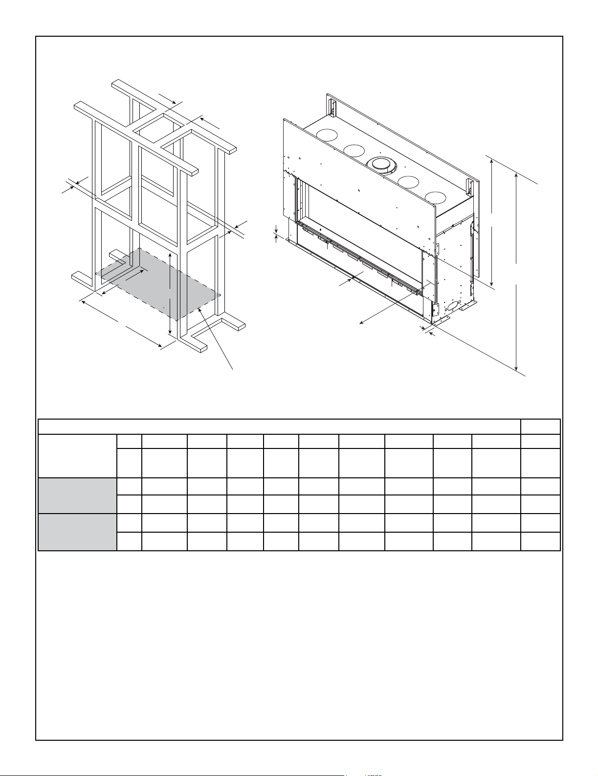
A
HEADER
DEPTH**
ECHEL36IN-C
Inches
Millimeters
ECHEL48IN-C
Inches
F
B
C
D
APPLIANCE MAY BE INSTALLED OFF OF FLOOR***
NOTE: E & K dimensions will change if
Passive Heat option is installed. Reference the instructions
included with the Passive Heat Kit for dimensions.
G
J
I
MINIMUM FRAMING DIMENSIONS*
A B C D E F G H I J K
Rough
Opening
(Vent Pipe)
10 42 18-1/4 48-1/4 31 0 0 1 1 48 55-1/2
254 1067 464 1226 787 0 0 25 25 1219 1410
Rough
Opening
(Height)
Rough
Opening
(Depth)
Rough
Opening
(Width)
Clearance
to Ceiling
Combustible
Floor
Combustible
Flooring
Behind
Appliance
Sides of
Appliance
Front of
Appliance
MINIMUM FRAMING DIMENSIONS*
A B C D E F G H I J K
Rough
Opening
(Vent Pipe)
10 42 18-1/4 60-1/4 31 0 0 1 1 48 55-1/2
Rough
Opening
(Height)
Rough
Opening
(Depth)
Rough
Opening
(Width)
Clearance
to Ceiling
Combustible
Floor
Combustible
Flooring
Behind
Appliance
Sides of
Appliance
Front of
Appliance
E
K
H
Clearance
to Ceiling
Clearance
to Ceiling
Millimeters
254 1067 464 1530 787 0 0 25 25 1219 1410
MINIMUM FRAMING DIMENSIONS*
A B C D E F G H I J K
ECHEL60IN-C
Inches
Millimeters
Rough
Opening
(Vent Pipe)
10 48 18-1/4 72-1/4 31 0 0 1 1 48 55-1/2
254 1219 464 1835 787 0 0 25 25 1219 1410
Rough
Opening
(Height)
Rough
Opening
(Depth)
Rough
Opening
(Width)
Clearance
to Ceiling
Combustible
Floor
Combustible
Flooring
MINIMUM FRAMING DIMENSIONS*
A B C D E F G H I J K
ECHEL72IN-C
Inches
Millimeters
Rough
Opening
(Vent Pipe)
10 48 18-1/4 84-1/4 31 0 0 1 1 48 55-1/2
254 1219 464 2140 787 0 0 25 25 1219 1410
Rough
Opening
(Height)
Rough
Opening
(Depth)
Rough
Opening
(Width)
Clearance
to Ceiling
Combustible
Floor
Combustible
Flooring
* = Adjust framing dimensions for interior sheathing (such as sheetrock)
**= Header depth not to exceed 3-1/2 inches.
***= If appliance is installed off of oor, maintain required clearances to combustibles.
Construct platform in accordance with local building codes
Behind
Appliance
Behind
Appliance
Sides of
Appliance
Sides of
Appliance
Front of
Appliance
Front of
Appliance
Clearance
to Ceiling
Clearance
to Ceiling
Figure 3.8 Clearances to Combustibles-ECHEL36IN-C, ECHEL48IN-C, ECHEL60IN-C, ECHEL72IN-C
Majestic • ECHEL36IN-C/STIN-C, ECHEL48IN-C/STIN-C, ECHEL60IN-C, ECHEL72IN-C Installation Manual • 2608-980 Rev. D • 9/19
17
HEADER
DEPTH**
E=MEASUREMENT FROM TOP
OF FIREPLACE OPENING
A
TO CEILING
J=MEASUREMENT FROM
BOTTOM OF FIREPLACE
TO CEILING
HEADER
DEPTH**
F
E
ECHEL36STIN-C
ECHEL48STIN-C
C
D
mm
mm
in.
in.
J
B
APPLIANCE MAY BE
INSTALLED OFF OF FLOOR***
NOTE: E & J dimensions will change if
Passive Heat option is installed. Reference the instructions
G
I
H
included with the Passive Heat Kit for dimensions.
MINIMUM FRAMING DIMENSIONS*
A B C D E F G H I J
Rough
Opening
(Vent Pipe)
10 42 17 48-1/4 31 0 0 1 48 55-1/2
254 1067 432 1226 787 0 0 25 1219 1410
10 42 17 60-1/4 31 0 0 1 48 55-1/2
254 1067 432 1530 787 0 0 25 1219 1410
Rough
Opening
(Height)
Rough
Opening
(Depth)
Rough
Opening
(Width)
Clearance
to Ceiling
Combustible
Floor
Combustible
Flooring
Sides of
Appliance
Front or
Rear of
Appliance
Clearance
to Ceiling
* = Adjust framing dimensions for interior sheathing (such as sheetrock)
**= Header depth not to exceed 3-1/2 inches.
***= If appliance is installed off of oor, maintain required clearances to combustibles.
Construct platform in accordance with local building codes.
Figure 3.9 Clearances to Combustibles-ECHEL36STIN-C, ECHEL48STIN-C
Majestic • ECHEL36IN-C/STIN-C, ECHEL48IN-C/STIN-C, ECHEL60IN-C, ECHEL72IN-C Installation Manual • 2608-980 Rev. D • 9/1918
C. Constructing the Appliance Chase
NOTICE: Install appliance on hard metal or wood surfaces
extending full width and depth. DO NOT install directly on
carpeting, vinyl, or any combustible material other than
wood.
WARNING! Risk of Fire! Maintain specied air space
clearances to appliance and vent pipe:
• Insulation and other materials must be secured to prevent
accidental contact.
• The chase must be properly blocked to prevent blown
insulation or other combustibles from entering and
making contact with replace or chimney.
• Failure to maintain airspace may cause overheating and
a re.
A chase is a vertical box-like structure built to enclose the
gas appliance and/or its vent system. In cooler climates
the vent should be enclosed inside the chase.
NOTICE: Treatment of ceiling restops and wall shield
restops and construction of the chase may vary with the
type of building. These instructions are not substitutes
for the requirements of local building codes. Therefore,
you MUST check local building codes to determine the
requirements to these steps.
NOTICE: When installing a sprinkler head in a replace
chase, it is recommended to use a sprinkler head with a
sprinkler activation temperature classied as Extra High.
Keep sprinkler head away from vent and chimney.
Chases should be constructed and insulated in the same
manner as the thermal envelope of the home based on
the code requirements for that climate zone to prevent air
leakage and draft problems. The chase is an extension of
the building thermal envelope.
To further prevent drafts and air leakage, the wall shield
and ceiling restops should be sealed with caulk or foil
tape with a minimum of 300 ºF continuous exposure
rating to seal gaps. Gas line holes and other openings
should be sealed with caulk with a minimum of 300 ºF continuous exposure rating or stuffed with unfaced insulation. If
the appliance is being installed on a cement surface, a layer
of plywood may be placed underneath to prevent conducting
cold up into the room.
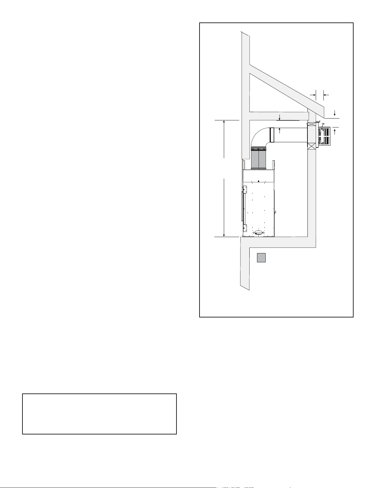
Minimum height requirements for an exterior chase on a
top-vented appliance are shown in Figure 3.10. Reference
Figure 4.4 for additional clearances.
A
3 IN. MIN.
ECHEL36 = 70 IN.
ECHEL48 = 70 IN.
ECHEL60 = 70 IN.
ECHEL72 = 82 IN.
REQUIRED MINIMUM OFF TOP
ECHEL36 = 18 IN.
ECHEL48 = 18 IN.
ECHEL60 = 18 IN.
ECHEL72 = 30 IN.
* NOTE: If overhang “A” is less than 2
inches, clearance from top of termination
cap to bottom of overhang “B” MUST be a
minimum of 4 inches. If A is two inches
or greater, see Figure 4.4, “Minimum
Clearances for Termination.”
Figure 3.10 Exterior Chase - Minimum Height Requirements
B*
Note: Figure 3.8 and Figure 3.9 show the replace installed on
the oor. However, this replace can be elevated off the oor
provided that the replace is properly supported by framing
materials and the ceiling clearances are maintained.
Majestic • ECHEL36IN-C/STIN-C, ECHEL48IN-C/STIN-C, ECHEL60IN-C, ECHEL72IN-C Installation Manual • 2608-980 Rev. D • 9/19
19

D. Floor Protection
NOTICE: Install appliance on hard metal or wood surfaces
extending full width and depth. DO NOT install directly
on carpeting, vinyl, tile or any combustible material other
than wood.
WARNING! Risk of Fire! Maintain specied air space
clearances to appliance and vent pipe:
• Insulation and other materials must be secured to prevent
accidental contact.
• The chase must be properly blocked to prevent blown
insulation or other combustibles from entering and
making contact with replace or chimney.
• Failure to maintain airspace could cause overheating
and re.
Elevated Hearth Systems
Some hearth systems will elevate the appliance off the
oor at a given dimension. The elevation will also have to
be added to the following: Wall penetration referenced in
Figure 5.2 (Wall penetration) and Rough Opening Height
(header height) referenced in Figure 3.8 and 3.9.
Note: Finished oor thickness should also be considered
when determining installation dimensions.
Majestic • ECHEL36IN-C/STIN-C, ECHEL48IN-C/STIN-C, ECHEL60IN-C, ECHEL72IN-C Installation Manual • 2608-980 Rev. D • 9/1920
HORIZONTAL
Termination Location and Vent Information
.
A B
152 mm/508 mm
457 mm
20 in. and over 0 in. minimum
4
A. Approved Pipe
WARNING! Risk of Fire, Delayed Ignition or Asphyxiation. This appliance requires a separate vent. DO NOT
vent to a pipe serving any other appliance.
This appliance is only approved for use with Hearth &
Home Technologies DVP venting systems. Refer to Section 12.A for vent component information and dimensions.
DO NOT mix pipe, ttings or joining methods from different manufacturers.
The pipe is tested to be run inside an enclosed wall.
There is no requirement for inspection openings at each
joint within the wall.
6 in. (minimum) up to 20 in.
Wood or Fuel Oil
Termination Cap
B
18 in. minimum
A *
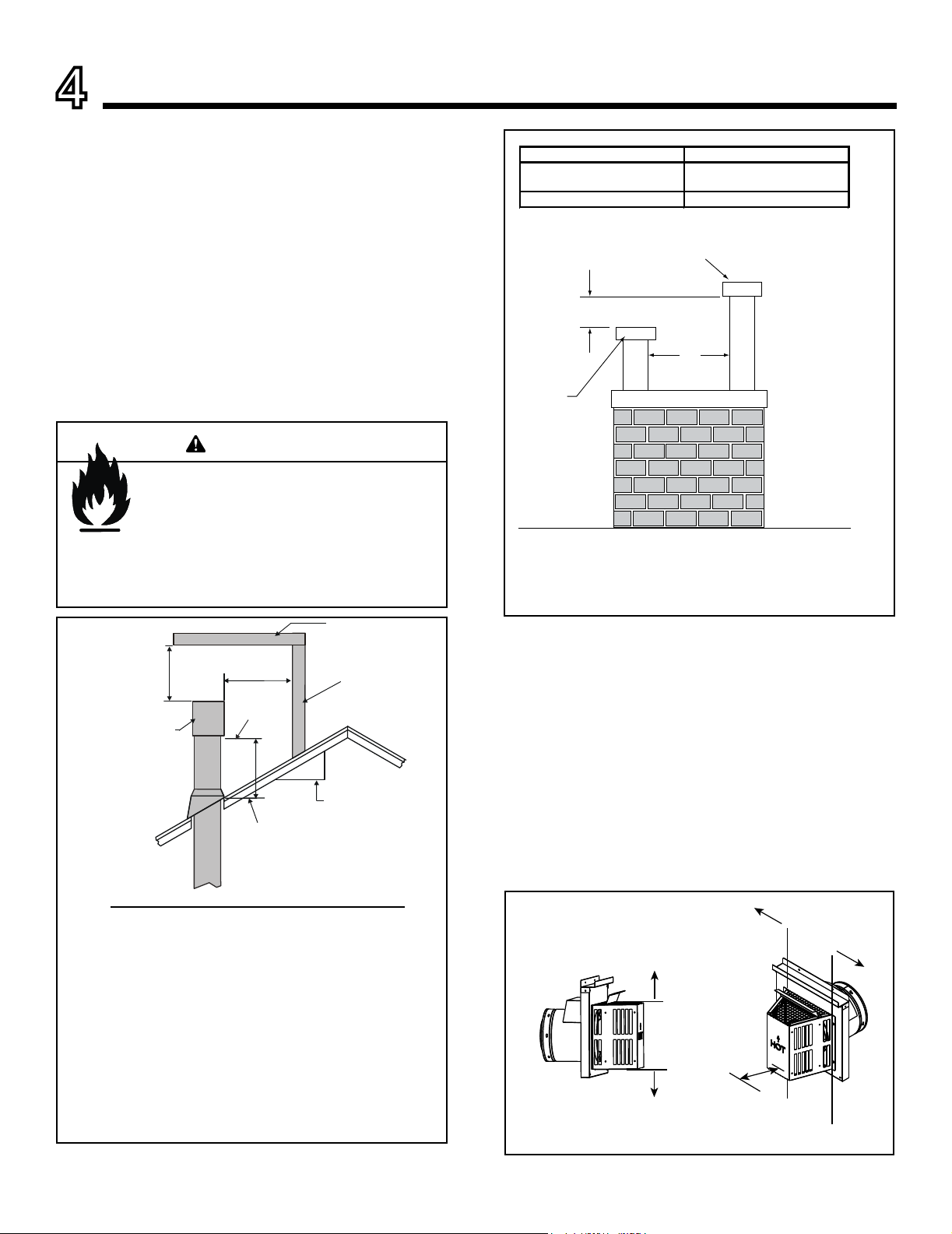
B. Vent Termination Minimum Clearances
WARNING
Fire Risk.
Maintain vent clearance to combustibles as
specied.
• DO NOT pack air space with insulation or other
materials.
Failure to keep insulation or other materials away
from vent pipe could cause overheating and re.
OVERHANG
2 FT.
MIN.
GAS DIRECT VENT
TERMINATION CAP
20 INCHES MIN.
LOWEST
DISCHARGE
OPENING
H (MIN.) - MINIMUM HEIGHT FROM ROOF
TO LOWEST DISCHARGE OPENING
X
12
ROOF PITCH
IS X/ 12
VERTICAL
WALL
**Gas
Termination
Cap
* If using decorative cap cover(s), this distance may need to be increased.
Refer to the installation instructions supplied with the decorative cap cover
** If two gas terminations are present, they may be level (B = 0 inches)
provided A is a minimum of 6 inches.
Figure 4.2 Staggered Termination Caps
CAUTION! Risk of Burns! Termination caps are HOT,
consider proximity to doors, trafc areas or where people
may pass or gather (sidewalk, deck, patio, etc.). Listed
cap shields available. Contact your dealer.
• Local codes or regulations may require different
clearances.
• Hearth & Home Technologies assumes no responsibility
for the improper performance of the appliance when the
venting system does not meet these requirements.
• Vinyl protection kits are suggested for use with vinyl siding.
• Measure horizontal and vertical termination cap clearances
as noted in Figure 4.3.
Roof Pitch H (Min.) Ft
Flat to 6/12...........................................................1.0*
Over 6/12 to 7/12 .................................................1.25*
Over 7/12 to 8/12 .................................................1.5*
Over 8/12 to 9/12 .................................................2.0*
Over 9/12 to 10/12 ...............................................2.5*
Over 10/12 to 11/12 .............................................3.25
Over 11/12 to 12/12 .............................................4.0
Over 12/12 to 14/12 .............................................5.0
Over 14/12 to 16/12 .............................................6.0
Over 16/12 to 18/12 .............................................7.0
Over 18/12 to 20/12 .............................................7.5
Over 20/12 to 21/12 .............................................8.0
* H minimum may vary depending on regional snowfall.
Refer to local codes.
Figure 4.1 Minimum Height From Roof to Lowest Discharge
Opening
Majestic • ECHEL36IN-C/STIN-C, ECHEL48IN-C/STIN-C, ECHEL60IN-C, ECHEL72IN-C Installation Manual • 2608-980 Rev. D • 9/19
H=Measure Horizontal Distances from H
V=Measure Vertical Distances from V
V
CLEARANCE
V
= 6 IN.
Figure 4.3
H
H
21
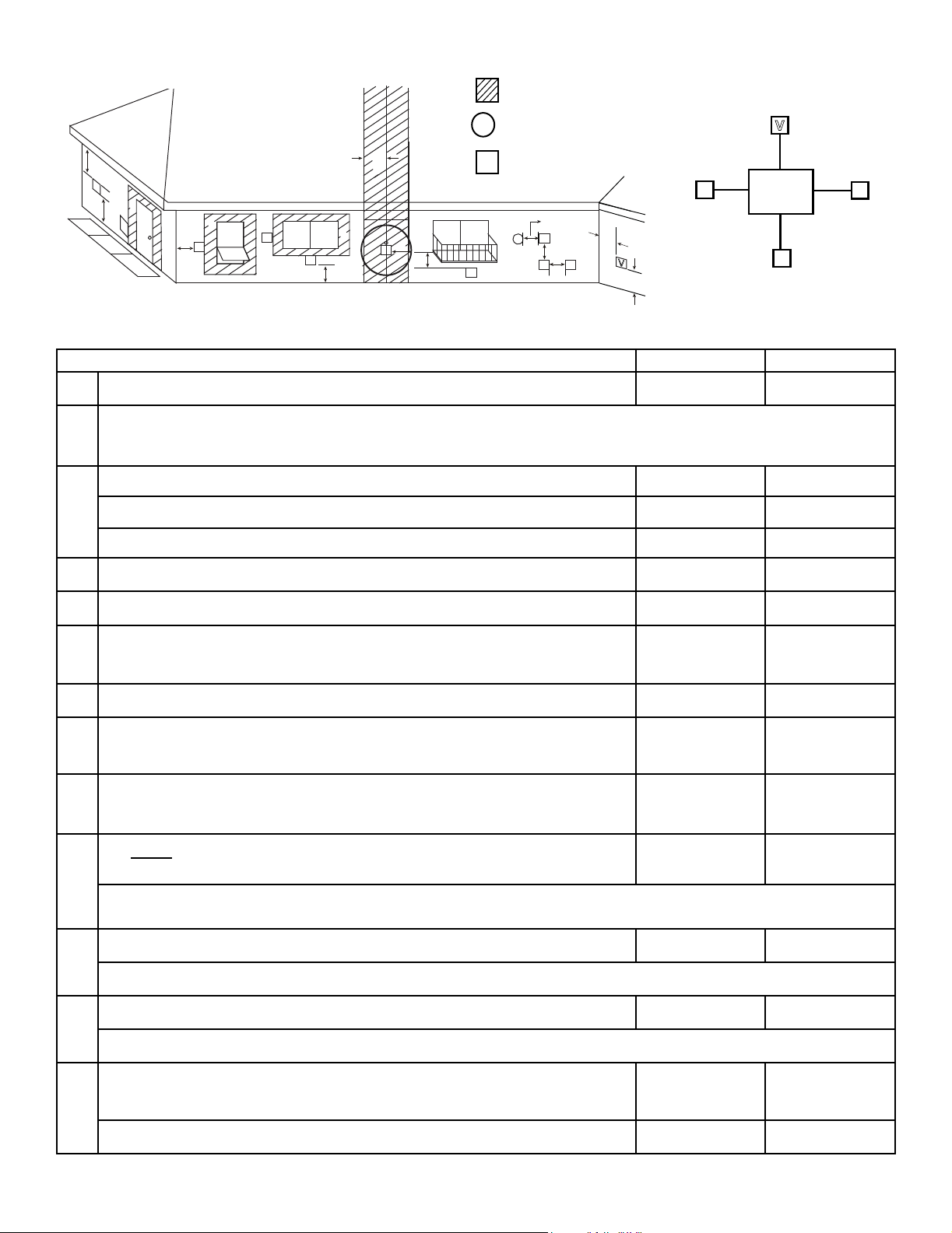
C. Vent Terminal Clearances
= AREA WHERE TERMINAL IS NOT PERMITTED
X
= AIR SUPPLY INLET
C
V
B
J
V
U.S.A. Installations: In accordance with the current ANSI Z223.1/NFPA 54, National Fuel Gas Code.
Canadian Installations: In accordance with the current CSA B149.1, Natural Gas and Propane Installation Code.
B
D
V
V
V
F
B
A
G
M
V
= VENT TERMINAL
H or i
V
X
V
V
H
H
E
V
V
A
V
U.S.A. CANADA
K
V
L
Electrical
Service
C
V
K
A Clearance above grade,veranda, porch, deck, or balcony 12 in. (305 mm) 12 in. (305 mm)
Clearance to window or door that may be opened, or to permanently closed window
B
U.S.A.: = 12 in. min. (305 mm min.) CANADA: = 12 in. min. (305 mm min.)
Clearance below unventilated soft 18 in. (457 mm) 18 in. (457 mm)
C
Clearance below ventilated soft 18 in. (457 mm) 18 in. (457 mm)
Clearance below any vinyl softs and electrical service 30 in. (762 mm) 30 in. (762 mm)
D Clearance to outside corner 6 in. (152 mm) 6 in. (152 mm)
V
E Clearance to inside corner 6 in. (152 mm) 6 in. (152 mm)
Not to be installed above a gas meter/regulator assembly within 3 feet horizontally from
F
the center-line of the regulator
3 ft (914 mm) 3 ft (914 mm)
G Clearance to gas service regulator vent outlet 3 ft (914 mm) 3 ft (914 mm)
Clearance to non-mechanical air supply inlet to building or the combustion air inlet to
H
any other appliance termination (mechanical or non-mechanical)
9 in.
(229 mm min.)
12 in.
(305 mm min.)
Clearance to a mechanical (powered) air supply inlet
I
***(All mechanical air intakes within 10 feet of a horizontal termination cap must be
3 ft (914 mm)*** 6 ft (1.8 m)
a minimum of 3 feet below termination.)
On public property: clearance above paved sidewalk or a paved driveway.
7 ft (2.1 m) 7 ft (2.1 m)**
J
**(A vent shall not terminate directly above a sidewalk or paved driveway which is located between two single family dwellings
and serves both dwellings.)
Clearance from sides of electrical service 6 in. (152 mm) 6 in. (152 mm)
K
Location of the vent termination must not interfere with access to the electrical service.
Clearance above electrical service 12 in. (305 mm) 12 in. (305 mm)
L
Location of the vent termination must not interfere with access to the electrical service.
Clearance under veranda, porch, deck, balcony or overhang
*(Permitted only if veranda, porch, deck, or balcony is fully open on a minimum of
M
two sides beneath the oor.)
Vinyl or composite overhang 42 in. (1067 mm) 42 in. (1067 mm)
Figure 4.4 Minimum Clearances for Termination
Majestic • ECHEL36IN-C/STIN-C, ECHEL48IN-C/STIN-C, ECHEL60IN-C, ECHEL72IN-C Installation Manual • 2608-980 Rev. D • 9/1922
18 in. (457 mm) 18 in. (457 mm)*
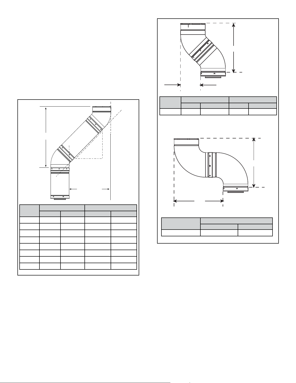
D. Use of Elbows
Diagonal runs have both vertical and horizontal vent aspects when calculating the effects. Use the rise for the
vertical aspect and the run for the horizontal aspect. See
Figure 4.5.
Two 45º elbows may be used in place of one 90º elbow.
On 45º runs, one foot of diagonal is equal to 8-1/2 inch
(216 mm) horizontal run and 8-1/2 inch (216 mm) vertical
run. A length of straight pipe is allowed between two 45º
elbows. See Figure 4.5.
Figure 4.6 shows the vertical and horizontal offsets for
DVP elbows.
Y
X
VERTICAL
EFFECTIVE
LENGTH
RUN
HORIZONTAL
DVP
Pipe
DVP4 4 102 2-3/4 70
DVP6 6 152 4-1/4 108
DVP12 12 305 8-1/2 216
DVP24 24 610 17 432
DVP36 36 914 25-1/2 648
DVP48 48 1219 34 864
DVP6A 3 to 6 76 to 152
DVP12A 3 to 12 76 to 305
Effective Length Rise/Run
Inches Millimeters Inches Millimeters
2-1/8-4-1/4 54-108
2-1/8-8-1/2 54-216
RISE
Vent
Type
DVP 4-1/2 11 4 17 432
Inches Millimeters Inches Millimeters
X Y
X
X
Vent Type
DVP 16-1/4 413
Figure 4.6 Vertical and Horizontal Offset for DVP Elbows
Inches Millimeters
X
Figure 4.5
Majestic • ECHEL36IN-C/STIN-C, ECHEL48IN-C/STIN-C, ECHEL60IN-C, ECHEL72IN-C Installation Manual • 2608-980 Rev. D • 9/19
23
E. Vent Diagrams
General Rules:
• SUBTRACT 3 ft from the total H measurement for each
90º elbow installed horizontally.
• SUBTRACT 1-1/2 ft from the total H measurement for
each 45º elbow installed horizontally.
• A maximum of three 90º elbows (or six 45º elbows) may
be used in any vent conguration. Some elbows may be
installed horizontally. See Figure 4.12 and Figure 4.19.
• Elbows may be placed back to back anywhere in the
system.
• Any 90º elbow may be replaced with two back to back
45º elbows.
• When penetrating a combustible wall, a wall shield
restop must be installed.
• When penetrating a combustible ceiling, a ceiling restop
must be installed.
• Horizontal runs of vent do not require vertical rise;
horizontal runs may be level.
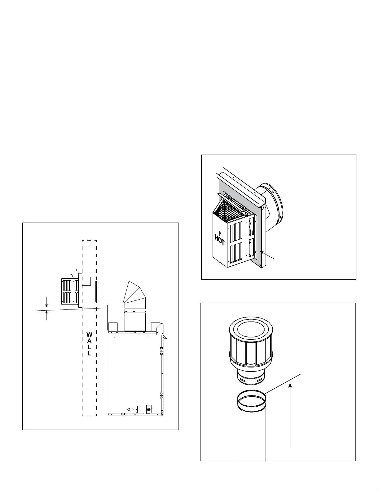
• Horizontal termination cap should have a 1/4 inch
downward slant to allow any moisture in cap to be
released. See Figure 4.7.
Measuring Standards:
Vertical and horizontal measurements listed in the vent
diagrams and clearances for termination were made
using the following standards:
• Pipe measurements are shown using the effective length
of pipe. See Section 12.A (Figure 12.1), for information
on effective length of pipe components.
• Horizontal terminations are measured to the outside
mounting surface (flange of termination cap). See
Figure 4.8.
• Vertical terminations are measured to top of last section
of pipe. See Figure 4.9.
• Horizontal pipe installed level with no rise.
• Horizontal and vertical termination clearances measured
to trapezoid portion of cap. See Figure 4.3.
1/4 in. max.
Figure 4.7
(6 mm)
MEASURE TO SHADED SURFACE
(OUTSIDE MOUNTING SURFACE)
Figure 4.8 Measure to Outside Mounting Surface
WALL
Figure 4.9 Measure to Top of Last Section of Pipe
Majestic • ECHEL36IN-C/STIN-C, ECHEL48IN-C/STIN-C, ECHEL60IN-C, ECHEL72IN-C Installation Manual • 2608-980 Rev. D • 9/1924
 Loading...