

Hearth&Home BRAVO, AZTEC Installer's Manual
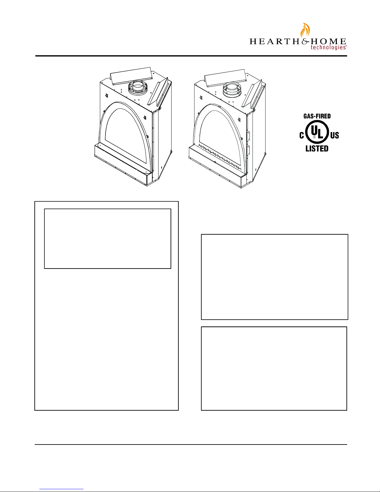
Models:
BRAVO
AZTEC
WARNING: IF THE INFORMATION
IN THESE INSTRUCTIONS IS NOT
FOLLOWED EXACTLY, A FIRE OR
EXPLOSION MAY RESULT CAUSING PROPERTY DAMAGE, PERSONAL INJURY, OR DEATH.
- Do not store or use gasoline or other flammable vapors and liquids in the vicinity of this
or any other appliance.
- What to do if you smell gas
• Do not try to light any appliance.
• Do not touch any electrical switch.
• Do not use any phone in your building.
• Immediately call your gas supplier from a
neighbor's phone. Follow the gas supplier's
instructions.
• If you cannot reach your gas supplier, call
the fire department.
- Installation and service must be performed by a
qualified installer, service agency, or the gas
supplier.
Installers Guide
Underwriters
Laboratories Listed
READ THIS MANUAL BEFORE INSTALLING OR
OPERATING THIS APPLIANCE. THIS INSTALLERS
GUIDE MUST BE LEFT WITH APPLIANCE FOR
FUTURE REFERENCE.
WARNING: IMPROPER INSTALLATION, ADJUSTMENT, ALTERATION,
SERVICE OR MAINTENANCE CAN
CAUSE INJURY OR PROPERTY DAMAGE. REFER TO THIS MANUAL. FOR
ASSISTANCE OR ADDITIONAL INFORMATION CONSULT A QUALIFIED INSTALLER, SERVICE AGENCY, OR THE
GAS SUPPLIER.
1. This appliance may be installed in an aftermarket, permanently located, manufactured (mobile) home, where not prohibited by local codes.
2. This appliance is only for use with the type
of gas indicated on the rating plate. This
appliance is not convertible for use with
other gases, unless a certified kit is used.
Printed in U.S.A. Copyright 2003,
Hearth & Home Technologies Inc.
20802 Kensington Boulevard, Lakeville, MN 55044
This product is covered by one or more of the following patents: (United States) 4,112,913; 4,408,594; 4,422,426; 4,424,792; 4,520,791; 4,793,322;
4,852,548; 4,875,464; 5,000,162; 5,016,609; 5,076,254 5,191,877; 5,218,953; 5,328,356; 5,429,495; 5,452,708; 5,542,407; 5,613,487; (Australia)
543790; 586383; (Canada) 1,123,296; 1,297,746; 2,195,264; (Mexico) 97-0457; (New Zealand) 200265; or other U.S. and foreign patents pending.
Please contact your Hearth & Home Technologies dealer with
any questions or concerns. For the number of your nearest Hearth
& Home Technologies dealer, please call 1-888-427-3973.
703-900E 4/03
SAFETY AND WARNING INFORMATION
READ and UNDERSTAND all instructions carefully
!
before starting the installation. FAILURE TO FOLLOW
these installation instructions may result in a possible
fire hazard and will void the warranty.
Prior to the first firing of the fireplace, READ the Using
!
Your Fireplace section of the Owners Guide.
DO NOT USE this appliance if any part has been under
!
water. Immediately CALL a qualified service technician
to inspect the unit and to replace any part of the control
system and any gas control which has been under
water.
THIS UNIT IS NOT FOR USE WITH SOLID FUEL.
!
Installation and repair should be PERFORMED by a
qualified service person. The appliance and venting
!
system should be INSPECTED before initial use and
at least annually by a professional service person.
More frequent cleaning may be required due to
excessive lint from carpeting, bedding material, etc. It
is IMPERATIVE that the unit’s control compartment,
burners, and circulating air passageways BE KEPT
CLEAN to provide for adequate combustion and
ventilation air.
These units MUST use one of the vent systems
!
described in the Installing the Fireplace section of the
Installers Guide. NO OTHER vent systems or
components MAY BE USED.
This gas fireplace and vent assembly MUST be vented
!
directly to the outside and MUST NEVER be attached
to a chimney serving a separate solid fuel burning
appliance. Each gas appliance MUST USE a separate
vent system. Common vent systems are PROHIBITED.
INSPECT the external vent cap on a regular basis to
!
make sure that no debris is interfering with the air
flow.
The glass door assembly MUST be in place and
!
sealed, and the trim door assembly MUST be in place
on the fireplace before the unit can be placed into
safe operation.
WARNING: DO NOT OPERATE this appliance with
!
the glass door removed, cracked, or broken. Broken
glass may be sharp to the touch, use caution when
removing. Replacement of the glass door should be
performed by a licensed or qualified service person.
DO NOT strike or slam the glass door.
Always KEEP the appliance clear and free from
!
combustible materials, gasoline, and other
flammable vapors and liquids.
NEVER OBSTRUCT the flow of combustion and
!
ventilation air. Keep the front of the appliance CLEAR
of all obstacles and materials for servicing and proper
operations.
Due to the high temperature, the appliance should be
LOCATED out of traffic areas and away from furniture
!
and draperies. Clothing or flammable material
SHOULD NOT BE PLACED on or near the appliance.
Children and adults should be ALERTED to the
!
hazards of high surface temperature and should STAY
AWAY to avoid burns or clothing ignition. Young
children should be CAREFULLY SUPERVISED when
they are in the same room as the appliance.
The glass door assembly SHALL ONLY be replaced
!
as a complete unit, as supplied by the gas fireplace
manufacturer. NO SUBSTITUTE material may be
used.
DO NOT USE abrasive cleaners on the glass door
!
assembly. DO NOT ATTEMPT to clean the glass door
when it is hot.
Turn off the gas before servicing this appliance. It is
recommended that a qualified service technician
!
perform an appliance check-up at the beginning of
each heating season.
Any safety screen or guard removed for servicing must
!
be replaced before operating this appliance.
DO NOT place furniture or any other combustible
!
household objects within 36 inches of the fireplace
front.
2

Table of Contents
Safety and Warning Information. ...................................2
Service Parts List...........................................................4
Section 1: Approvals and Codes. ..................................8
Appliance Certification ......................................................8
Installation Codes .............................................................8
High Altitude Installations...................................................8
u
Section 2: Getting Started. ............................................9
Introducing the Hearth Technologies Gas Fireplaces ........9
Pre-installation Preparation...............................................9
Section 3: Installing the Fireplace. ............................. 11
Constructing the Fireplace Chase...................................11
Step 1 Locating the Fireplace ...................................... 11
Step 2 Framing the Fireplace ......................................12
Step 3 Installing the Vent System.................................12
A. Vent System Approvals................................12
u
B. Installing Vent Components .........................20
u
C. Vent Termination .........................................23
u
Step 4 Positioning, Leveling, and
Securing the Fireplace .....................................26
Step 5 The Gas Control Systems................................26
Step 6 The Gas Supply Line ........................................27
Step 7 Gas Pressure Requirements............................27
Step 8 Wiring the Fireplace .........................................28
Step 9 Finishing...........................................................29
Step 10 Installing Trim, Logs, and Ember Material .........31
Installing the Trim .............................................31
Positioning the Logs .........................................31
Shutter Settings................................................31
Placing the Ember Material...............................31
Glass Specifications.........................................31
Step 11 Before Lighting the Fireplace ............................32
u
Step 12 Lighting the Fireplace .......................................32
After the Installation.........................................................32
Section 4: Maintaining and Servicing
u = Contains updated information.
Your Fireplace. ...........................................33
3
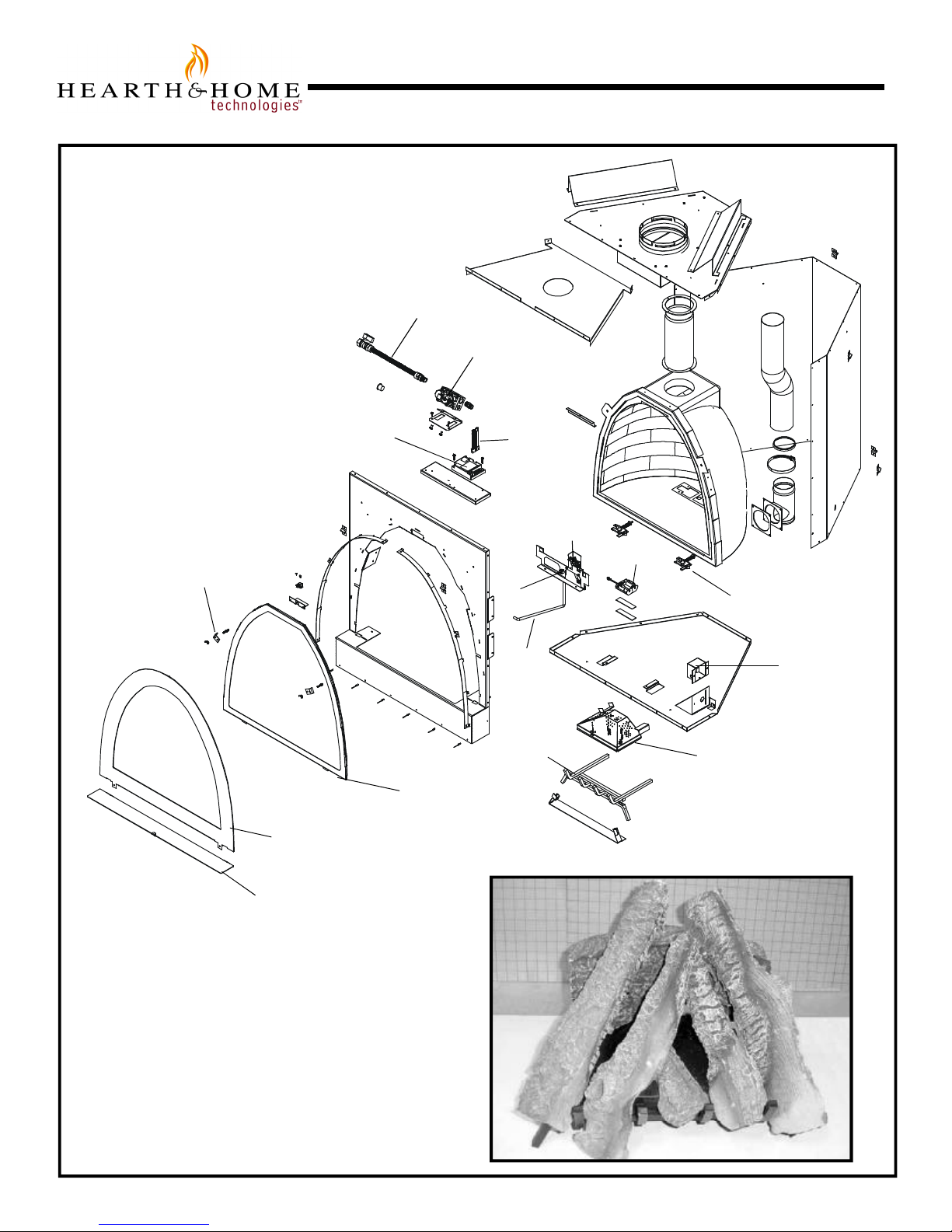
Service Parts
BRAVO
(NG, LP) Exploded Parts Diagram
(GN, PL) Vue éclatée des pièces
23
15
16
17
Beginning Manufacturing Date: 2-01
Ending Manufacturing Date: ______
19
21
22
3
2
1
18
5
8 Log Assembly
9
20
7
6
4
Part number list on following page.
*
La liste des numéros de pièce se
*
trouve à la page suivante.
14
12
4
11
10
13

Service Parts List / Liste des pièces de rechange
BRAVO
IMPORTANT: THIS IS DATED INFORMA TION. The most current information is located on your dealers VIP site. When ordering,
supply serial and model numbers to ensure correct service parts. / IMPORTANT : L'information fournie dans cette brochure n'est
valide que pendant une courte période. Les sites VIP des distributeurs disposent des renseignements les plus récents. Lors
d'une commande, veuillez fournir les numéros de série et de modèles pour un remplacement adéquat des pièces.
ITEM /
PIÈCE
IPI IGNITION
SERIAL #
/ N° DE SÉRIE
PART NUMBER
/ N° DE PIÈCE
1 Main Burner Orifice NG (#42A) / Orifice de brûleur GN (#42A) 060-800
1 Main Burner Orifice LP (#53A) / Orifice de brûleur GN (#53A) 060-801
2 Glass Door Assembly / Module de Porte en verre GLA-BRAVO
3 Decorative Front (Includes Mesh) / Avant décoratif (Écran) 704-136A
4 Burner NG / Brûleur GN 704-176A
4 Burner LP / Brûleur PL 704-175A
5 Log Grate / Grille de Bûche 704-360A
6 Junction Box / Boîtier de dérivation 100-250A
7 Glass Latch / Verrou De verre SRV550-121A
8 Log Set Assembly / Jeu de Bûches LOGS-BRAVO
9 Log 1 Back Log / Bûche 1 SRV750-703
10 Log 2 Right Inside Log / Bûche 2 SRV750-705
11 Log 3 Small Log / Bûche 3 SRV750-706
12 Log 4 Left Inside Log / Bûche 4 SRV750-704
13 Log 5 Right Log / Bûche 5 SRV704-702
14 Log 6 Left Log / Bûche 6 SRV704-701
15 Valve NG / Valve GN 593-500
15 Valve LP / Valve PL 593-501
16 Module / Module 593-592
17 Wire Assembly / Module de fil 593-590A
18 18" Flex 3/8" Diameter 567-301A
19 Pilot Assembly NG (must order whole assembly) / Module de veilleuse GN
19 Pilot Assembly LP (must order whole assembly) / Module de veilleuse PL
PRE 00241284
POST 00241284
PRE 00240038
POST 00240038
593-510A
593-512A
593-511A
593-513A
20 Battery Pack / Paquet de Batterie(Pile) 593-594A
21 Glass Retainer / Le verre de retenue 704-235
22 Decorative Front Base / Avant décoratif base 704-137
23 Flex Ball Valve Assembly / Fléchir l'Assemblée de Soupape de Balle 302-320A
ACCESSORIES / ACCESSOIRES
Trim Door Mesh / Encadrement de Porte de Écran MESH-BRAVO
Remote Control Kit / Module de commande à distance RC-SMART-HNG
Remote Control Kit / Module de commande à distance SMART-STAT-HNG
Remote Control Kit / Module de commande à distance SMART-BATT-HNG
Wall Switch Kit, Off-white / Interrupteur mural, blanc crème WSK-21
Wall Switch Kit, White / Interrupteur mural, blanc WSK-21-W
Black Mesh Panel Door (Standard) / Engrener la Porte de Panneau, Noir DF-Bravo-BK
Pewter Mesh Panel Door / Pewter Engrener la Porte de Panneau DF-Bravo-PWT
Cabinet Mesh Doors, Black / La Porte de Maille de placard, Noir CDM-Bravo-BK
Cabinet Mesh Doors, Pewter / La Porte de Maille de placard, Pewter CDM-Bravo-PWT
Conversion Kit NG SPI / Module de conversion GN SPI NGKP-BRAVO
Conversion Kit LP SPI / Module de conversion PL SPI LPKP-BRAVO
3V Adaptor / 3V Adapteur 593-593A
5

Service Parts
AZTEC
(NG, LP) Exploded Parts Diagram
(GN, PL) Vue éclatée des pièces
25
17
18
19
Beginning Manufacturing Date: 3-02
Ending Manufacturing Date: ______
21
23
3
24
Part number list on following page.
*
La liste des numéros de pièce se
*
trouve à la page suivante.
1
20
2
8 Log Assembly
14
5
11
13
12
22
7
6
4
9
16
15
10
6

Service Parts List / Liste des pièces de rechange
AZTEC
IMPORTANT: THIS IS DATED INFORMA TION. The most current information is located on your dealers VIP site. When ordering,
supply serial and model numbers to ensure correct service parts. / IMPORTANT : L'information fournie dans cette brochure n'est
valide que pendant une courte période. Les sites VIP des distributeurs disposent des renseignements les plus récents. Lors
d'une commande, veuillez fournir les numéros de série et de modèles pour un remplacement adéquat des pièces.
ITEM /
PIÈCE
IPI IGNITION
SERIAL #
/ N° DE SÉRIE
PART NUMBER
/ N° DE PIÈCE
1 Main Burner Orifice NG (#42A) / Orifice de brûleur GN (#42A) 060-800
1 Main Burner Orifice LP (#53A) / Orifice de brûleur GN (#53A) 060-801
2 Glass Door Assembly / Module de Porte en verre GLA-BRAVO
3 Decorative Front (Includes Mesh) / Avant décoratif (Écran) 703-136A
4 Burner NG / Brûleur GN 704-176A
4 Burner LP / Brûleur PL 704-175A
5 Log Grate / Grille de Bûche 704-360A
6 Junction Box / Boîtier de dérivation 100-250A
7 Glass Latch / Verrou De verre SRV550-121A
8 Log Set Assembly / Jeu de Bûches LOGS-AZTEC
9 Log 1 Back Log / Bûche 1 SRV703-701
10 Log 2 Front Right Log / Bûche 2 SRV703-702
11 Log 3 Front Left Log / Bûche 3 SRV703-703
12 Log 4 Front Left Inside Log / Bûche 4 SRV750-705
13 Log 5 Left Side Log / Bûche 5 SRV703-704
14 Log 6 Left Center Front Log / Bûche 6 SRV750-706
15 Log 7 Right Side Log / Bûche 7 SRV750-704
16 Log 8 Right Center Log / Bûche 8 SRV703-705
17 Valve NG / Valve GN 593-500
17 Valve LP / Valve PL 593-501
18 Module / Module 593-592
19 Wire Assembly / Module de fil 593-590A
20 18" Flex 3/8" Diameter 567-301A
21 Pilot Assembly NG (must order whole assembly) / Module de veilleuse GN
21 Pilot Assembly LP (must order whole assembly) / Module de veilleuse PL
PRE 00241284
POST 00241284
PRE 00240038
POST 00240038
593-510A
593-512A
593-511A
593-513A
22 Battery Pack / Paquet de Batterie(Pile) 593-594A
23 Glass Retainer / Le verre de retenue 704-235
24 Decorative Front Base / Avant décoratif base 704-137
25 Flex Ball Valve Assembly / Fléchir l'Assemblée de Soupape de Balle 302-320A
ACCESSORIES / ACCESSOIRES
Trim Door Mesh / Encadrement de Porte de Écran MESH-BRAVO
Remote Control Kit / Module de commande à distance RC-SMART-HTL
Remote Control Kit / Module de commande à distance SMART-STAT-HTL
Pewter Mesh Panel Door / La Porte de Panneau de Maille de Pewter DF-Bravo-PWT
Conversion Kit LP / Module de conversion PL DCKP-AZTEC
Conversion Kit NG / Module de conversion PL DCKN-AZTEC
Lava Rock Bag / Le Sac de Rocher de lave 705-420
Mystic Embers / Braises mystiques Mystic-Embers
3V Adaptor / 3V Adapteur 593-593A
7

Approvals and Codes
Appliance Certification
The Hearth & Home Technologies fireplace model discussed
in this Installers Guide have been tested to certification
standards and listed by the applicable laboratories.
Certification
MODEL: BRAVO, AZTEC
LABORATORY: Underwriters Laboratories
TYPE: Vented Gas Fireplace Heater
STANDARD: ANSI Z21.88-1998•CSA2.33-M98•UL307B
ANSI Z21.88-2000•CSA2.33-M00•UL307B
Installation Codes
The fireplace installation must conform to local codes. Before
installing the fireplace, consult the local building code
agency to ensure that you are in compliance with all
applicable codes, including permits and inspections.
In the absence of local codes, the fireplace installation must
conform to the National Fuel Gas Code ANSI Z223.1 (in the
United States) or the CAN/CGA-B149 Installation Codes
(in Canada). The appliance must be electrically grounded
in accordance with local codes or, in the absence of local
codes with the National Electric Code ANSI/NFPA No. 70
(in the United States), or to the CSA C22.1 Canadian Electric
Code (in Canada).
High Altitude Installations
U.L. Listed gas appliances are tested and approved without
requiring changes for elevations from 0 to 2,000 feet in the
U. S. A. and in Canada.
When installing this appliance at an elevation above 2,000
feet, it may be necessary to decrease the input rating by
changing the existing burner orifice to a smaller size. Input
rate should be reduced by 4% for each 1000 feet above a
2000 foot elevation in the U.S.A. or 10% for elevations
between 2000 and 4500 feet in Canada. If the heating value
of the gas has been reduced, these rules do not apply. To
identify the proper orifice size, check with the local gas
utility.
If installing this appliance at an elevation above 4,500 feet
(in Canada), check with local authorities.
These models may be installed in a bedroom or bed-sitting
room in the U.S.A. and Canada.
8

Getting Started
Introducing the Hearth & Home Technologies
Gas Fireplaces
Hearth & Home Technologies direct vent gas fireplaces are
designed to operate with all combustion air siphoned from
outside of the building and all exhaust gases expelled to
the outside.
The information contained in this Installers Guide, unless
noted otherwise, applies to all models and gas control
systems. Gas fireplace diagrams, including the dimensions,
are shown in this section.
Pre-install Preparation
This gas fireplace and its components are tested and safe
when installed in accordance with this Installers Guide.
Report to your dealer any parts damaged in shipment,
particularly the condition of the glass. Do not install any
unit with damaged, incomplete, or substitute parts.
The vent system components and trim doors are shipped
in separate packages. The gas logs may be packaged
separately and must be field installed.
Read all of the instructions before starting the
installation. Follow these instructions carefully during
the installation to ensure maximum safety and benefit.
Failure to follow these instructions will void the
owner’s warranty and may present a fire hazard.
Warranty
The Hearth & Home Technologies Warranty will be voided
by, and Hearth & Home Technologies disclaims any
responsibility for, the following actions:
• Installation of any damaged fireplace or vent system component.
• Modification of the fireplace or direct vent system.
• Installation other than as instructed by Hearth & Home
Technologies.
• Improper positioning of the gas logs or the glass door.
• Installation and/or use of any component part not manufactured and approved by Hearth & Home Technologies, not
withstanding any independent testing laboratory or other
party approval of such component part or accessory.
ANY SUCH ACTION MAY POSSIBLY CAUSE A FIRE
HAZARD.
When planning a fireplace installation, it’s necessary to
determine:
• Where the unit is to be installed.
• The vent system configuration to be used.
• Gas supply piping.
• Electrical wiring.
• Framing and finishing details.
• Where to install wall switch.
• Whether an optional remote control is desired.
If the fireplace is to be installed on carpeting or tile, or on
any combustible material other than wood flooring, the
fireplace should be installed on a metal or wood panel that
extends the full width and depth of the fireplace.
9
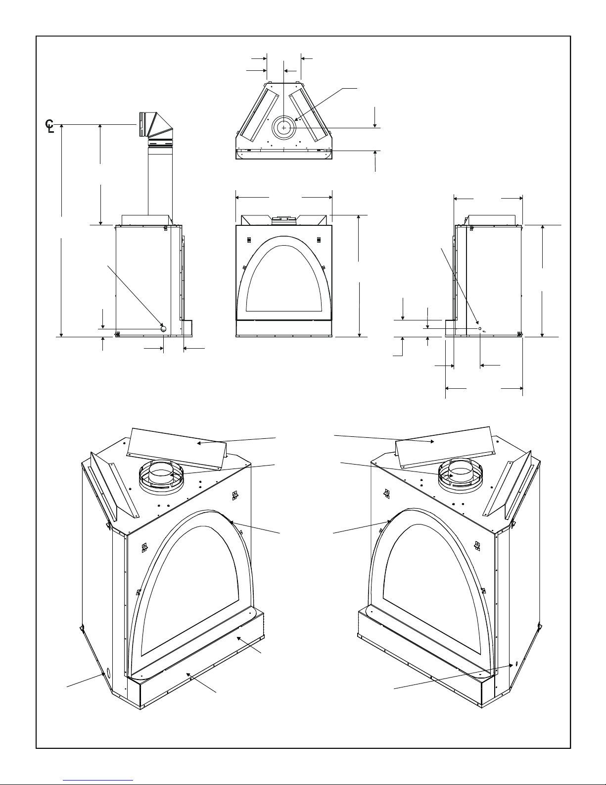
8 1/4 (209mm)
6 (154mm)
23 3/4
(628mm)
40
(1015mm)
(NOT FROM FRONT
3 1/8
(79mm)
(156mm)
43 1/2
(1104mm)
12 1/8 (308mm)
76
(1930mm)
36
(914mm)
GAS LINE
ACCESS
2 7/8 (74mm)
7 1/8
(182mm)
34 3/8
(875mm)
Ø8 (Ø203mm)
6 1/8
All dimensions in the front to back
direction are taken from the 1/2”
standoffs on the front face of the unit.
ELECTRICAL
ACCESS
9 3/8
(237mm)
27 3/4
(706mm)
STANDOFFS)
u
GAS LINE
ACCESS
GAS
CONTROLS
TOP STANDOFFS
TOP VENT COLLARS
FINISH EDGE
TRIM
RATING PLATES
AND LABELS
ELECTRICAL
ACCESS
Figure 1. Diagram of the BRAVO and AZTEC
10
 Loading...