

Page 1
Installation
Instructions
Models:
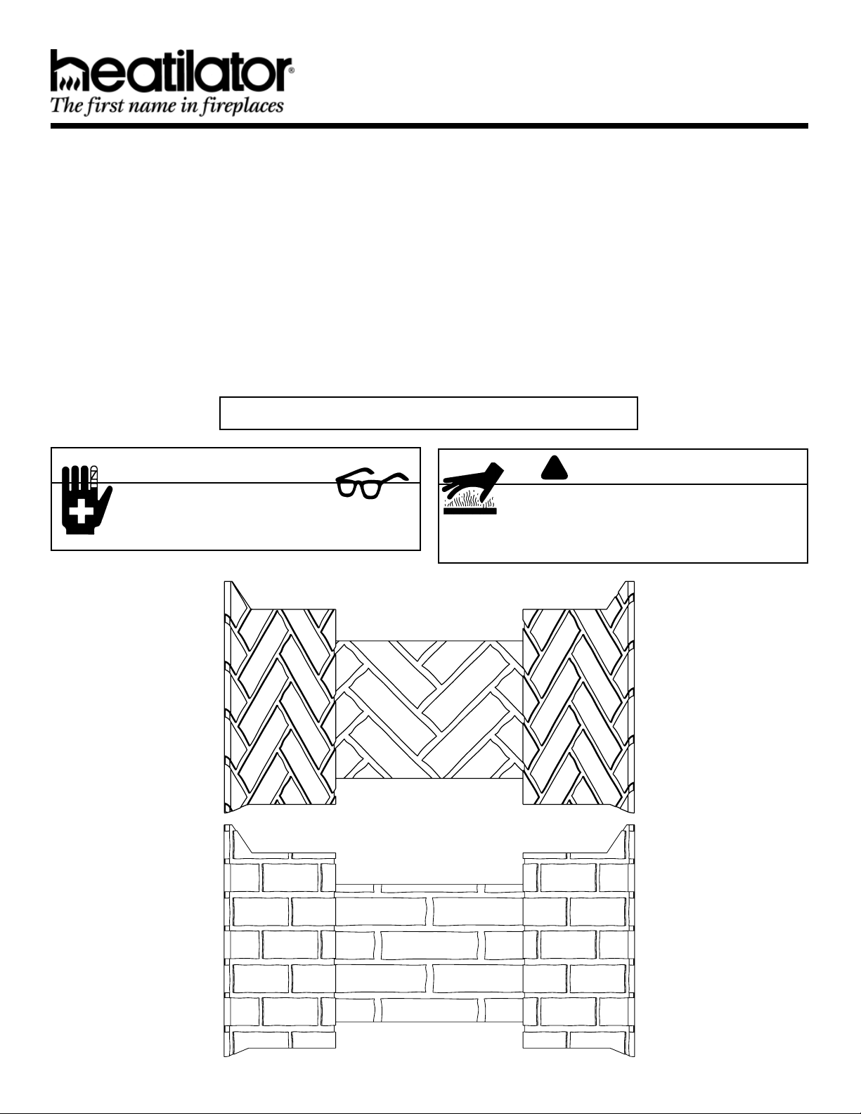
WHB30, WHB33, WHB36, WHB42
WTB30, WTB33, WTB36, WTB42
These refractories are intended for use with the Novus NDV and NBV Series gas appliances. Check with your local building code agency before you begin installation to ensure compliance with local codes, including the need for permits and
follow-up inspections. If you encounter any problems regarding code approvals, or if you need clarifi cation of any of the
instructions contained here, contact your Hearth & Home Technologies Inc. dealer. For the dealer nearest you, please visit
www.heatilator.com
Note: An arrow (¨) found in the text signifi es change in content.
CAUTION
Sharp Edges
• Wear protective gloves and safety
glasses during installation.
WHB
WARNING
!
Hot Surfaces
• Install this refractory only after the appliance
has cooled and the gas and electricity have
been shut off..
WTB
Heatilator • WHB/WTB Refractory • 4055-186 Rev C • 03/08
1
Page 2
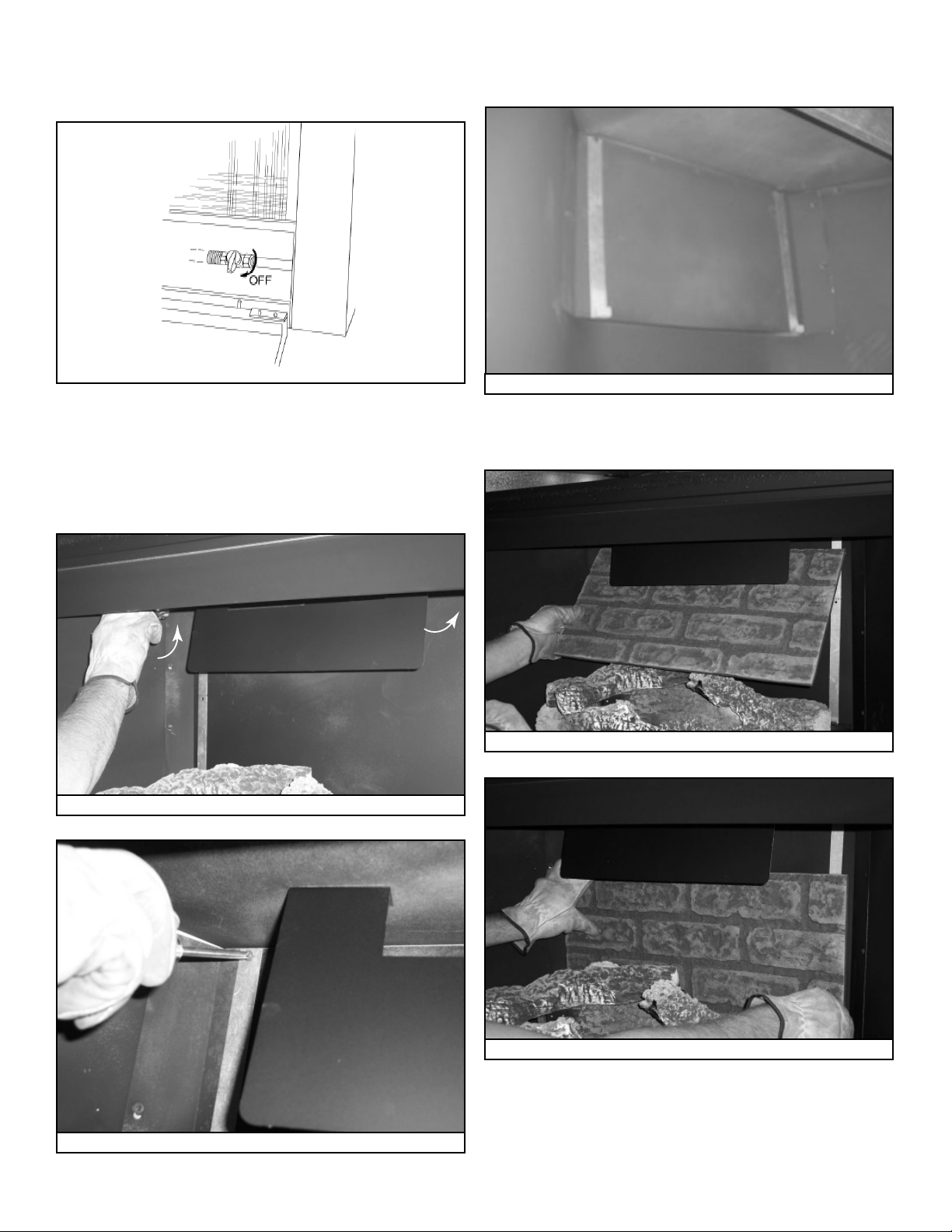
1. Shut off the electricity to the appliance and turn the gas
shutoff valve to the closed position. See Figure 1. Remove
the screen and glass from the appliance.
Make sure to shorten the bracket if installing in a B-vent
unit. See Figure 4.
Figure 1 - Gas Shutoff Valve
2. If installing this refractory into a B-Vent Appliance, please
go to “To Convert Refractory Kit to Fit B-Vent Appliance”
on page 4 of this manual.
3. Attach the two long hook-shaped brackets by removing
the two outside screws on the false back and reinstall the
screws. See Figures 2 and 3.
Figure 2 Location of Hook-Shaped Brackets
Figure 4 Shorten Brackets for B-Vent Installation
4. Set the back refractory piece into the brackets. See
Figures 5 and 6.
Figure 5 Position Back Refractory for Placement
Figure 3 Loosen Brackets
2
Figure 6 Set Back Refractory in Place
Heatilator • WHB/WTB Refractory • 4055-186 Rev C • 03/08
Page 3

5. If lava rock has been placed in appliance, clean the rock
away from the fi rebox sides to make room for the side
refractory. See Figure 7.
Figure 7 Move Lava Rock to Install Side Refractory
6. Carefully install a side refractory. See Figures 8 and 9.
7. To secure the side refractory in place, remove either the
middle or back screw in the fi rebox top. Attach a refractory
bracket (using the screw removed) to the fi rebox top. See
Figure 10.
Figure 10 Attach Refractory Bracket
8. Repeat Step 3 to install the other side refractory piece.
See Figure 11.
Figure 8 Position Side Refractory
Figure 9 Set Side Refractory in Place
Figure 11 Install Other Side Refractory
9. Adjust the back and sides so no gaps are visible in the
corners where the pieces come together.
10. Repeat Step 7. to install the other side.
11. Reinstall the fi xed glass assembly and screen.
12. Restore power and gas fl ow. Your refractory installation
is now complete.
Heatilator • WHB/WTB Refractory • 4055-186 Rev C • 03/08
3
Page 4

12. Convert Refractory Kit to Fit B-Vent Appliance
a. Locate the back refractory piece and lay the brick side down
on a fl at surface. Locate the indicator marks on the back
of the refractory piece. Lay a straight edge on the indicator
marks and cut with a utility knife. See Figure 8.
Figure 8
b. B-Vent/Herringbone - cut at line, discard lower (smaller)
portion. Install cut side down. Refer to Figure 9.
c. Direct Vent/Herringbone - Install whole refractory.
(back of Herringbone refractory)
(bottom for b-vent)
Figure 9
d. B-Vent/Traditional - cut at line, discard upper (smaller)
portion. Install cut side down. Refer to Figure 10.
e. Direct Vent/Traditional - Install whole refractory.
(back of Traditional refractory)
4
(bottom for b-vent)
Figure 10
Heatilator • WHB/WTB Refractory • 4055-186 Rev C • 03/08
 Loading...