

Hearth and Home Technologies VRT-BZ-N-CE, VRT-BZ-P-CE, VRT-GY-N-CE, VRTIKL-CE, VRT-GY-P-CE User Manual
...Page 1
VRTIKL-CE
FREESTANDING STOVE
MODEL:
VRT-BZ-N-CE
VRT-GR-N-CE
VRT-GY-P-CE
VRT-BZ-B-CE
Installer’s Guide
Installation and Operation
0063-06
VRT-GY-N-CE
VRT-BZ-P-CE
VRT-GR-B-CE
VRT-GY-B-CE
VRT-GR-P-CE
CAUTION
DO NOT DISCARD THIS MANUAL
• Important operating
and maintenance
instructions included.
WARNING: If the information in these
instructions is not followed exactly, a fi re
or explosion may result causing property
damage, personal injury, or death.
• Do not store or use gasoline or other fl am-
mable vapors and liquids in the vicinity of this
or any other gas stove.
• What to do if you smell gas
- Do not try to light any gas stove. Do not
touch any electrical switch. Do not use
any phone in your building.
- Immediately call your gas supplier from a
neighbor’s phone. Follow the gas supplier’s
instructions.
- If you cannot reach your gas supplier, call
the fi re department.
• Installation and service must be performed
by a qualifi ed installer, service agency, or the
gas supplier.
• Read, understand and follow
these instructions for safe
installation and operation.
DO NOT
DISCARD
• Leave this manual with
party responsible for
use and operation.
WARNING
HOT SURFACES!
Glass and other surfaces are hot during
operation AND cool down.
Hot glass will cause burns.
• DO NOT touch glass until it is cooled
• NEVER allow children to touch glass
• Keep children away
• CAREFULLY SUPERVISE children in same room as
fi replace.
• Alert children and adults to hazards of high temperatures.
High temperatures may ignite clothing or other fl ammable
materials.
• Keep clothing, furniture, draperies and other fl ammable
materials away.
This appliance has been supplied with an integral barrier
to prevent direct contact with the fi xed glass panel. DO
NOT operate the appliance with the barrier removed.
Contact your dealer if the barrier is not present or help is
needed to properly install one.
Installation and service of this gas stove should be performed
by qualifi ed personnel.
These instructions are valid for the following countries:
GB, IE
Î
1Heat & Glo • VRTIKL-CE • 7031-292 Rev E • 12/07
Page 2
Read this manual before installing or operating this gas stove.
Please retain this owner's manual for future reference.
Congratulations
Congratulations on selecting a Heat & Glo gas stove - an
elegant and clean alternative to wood burning stoves. The
Heat & Glo gas stove you have selected is designed to
provide the utmost in safety, reliability, and efficiency.
As the owner of a new gas stove, you'll want to read and
carefully follow all of the instructions contained in this
Owner's Manual. Pay special attention to all Cautions and
Warnings.
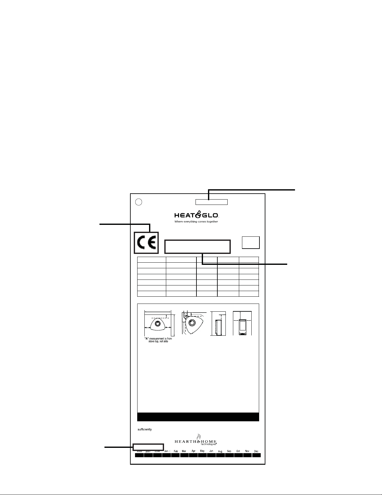
SAMPLE OF RATINGS LABEL
LOCATION: IN CONTROL AREA, INSIDE LOWER ACCESS DOOR
SERIAL NO.
Test Lab &
Report No.
Gas Type G20 G20 G20 G25
Destination ES, GB, IE, PT, NO DE, LU FRNL
CAT
Qn 7.6 7.6 7.6 6.2
Pn 20 mbar 20 mbar 20/25 mbar 25 mbar
Pmax 8.7 mbar 8.7 mbar 8.7 mbar 8.7 mbar
Injector #39DMS #39DMS #39DMS #39DMS
Heat & Glo, a brand of Hearth & Home Technologies, Inc.
0087
F
A
20802 Kensington Boulevard
Lakeville, MN 55044, USA
Model:
I
2H
Not for use with solid fuel.
B
E
This Owner's Manual should be retained for future reference.
We suggest that you keep it with your other important
documents and product manuals.
The information contained in this Owner's Manual, unless
noted otherwise, applies to all models and gas control
systems.
Y our new Heat & Glo gas stove will give you years of durable
use and trouble-free enjoyment. Welcome to the Heat & Glo
family of gas stove products!
Serial No.
ww w.heatnglo.com
ION
-CE
MADE
IN USA
Model Name
I
2E
C
C
I
2E R
H
D
Alcove
G
AAA
I
2L
Minimum Clearances to Combustibles
A - Side of appliance top to side wall..............15.2 cm
B - Rear of appliance to back wall................... 7.6 cm
C - Corner of appliance top to side wall..........12.7 cm
D - MinimumAlcove Height...........................137.2 cm
E - MaximumAlcove Depth ............................91.4 cm
SAMPLE
F - MinimumAlcove Width............................. 78.1 cm
G- Top of appliance to alcove ceiling ........... 33.7 cm
H - Mantle Clearance from appliance top .......26.7 cm
DO NOT REMOVE OR COVER THIS LABEL.
This appliance must be installed in accordance with the codes enforced, and used only in
ventilatedspace. Consult instructionsbefore installation anduse of this appliance.
Manufactured by:
Manufactured
Date of Manufacture:
Date
2 Heat & Glo • VRTIKL-CE • 7031-292 Rev E • 12/07
Page 3

- TABLE OF CONTENTS -
Section 1: Listing and Code Approvals
A. Gas Stove Certifi cations ...........................4
B. Glass Specifi cations .................................4
C. Non-Combustible Materials ......................4
D. Combustible Materials ..............................4
Section 2: Getting Started
A. Design & Installation Considerations ........5
B. Inspect Gas Stove & Components ............5
Section 3: Gas Stove Location & Clearances
A. Selecting Gas Stove Location ...................6
B. Clearances to Combustibles .....................6
C. Optional Stone Surround Installed ............7
Section 4: Termination Locations
A. Flue Termination Clearances ....................8
Section 5: Flue Information
A. Flueing Components ...............................10
B. Use of Elbows .........................................10
C. Measuring Standards ..............................10
D. Flueing Diagrams ....................................11
E. Horizontal Termination ............................16
F. Slim Line Wall Thimble ..........................17
G. Vertical Termination ................................19
H. Vertical Flue Restrictor ...........................21
Section 6: Gas Information
A. Gas Pressure Requirements ..................22
B. Gas Connection.. ....................................22
Section 7: Electrical Information
A. Ignition System Wiring ............................23
Section 8: Gas Stove Setup
A. Remove Shipping Materials ....................24
B. Unbolting Gas Stove from the Pallet .......24
C. Leveling and Lagging Down the
Gas Stove ...............................................24
D. Accessories ............................................25
E. Top to Rear Vent Conversion .................25
F. Installing the Baffl e .................................26
G. Positioning the Logs ...............................27
H. Mineral Wool ...........................................27
I. Front Door Glass Assembly ....................28
J. Inner Glass Door Replacement ..............28
Section 9: Operating Instructions
A. Before Lighting Gas Stove ......................29
B. Lighting Gas Stove .................................30
C. After Gas Stove is Lit ..............................31
D. Frequently Asked Questions ...................31
Section 10: Maintaining & Servicing Gas Stove
A. Maintenance Tasks ..........................................33
B. Service and Maintenance Log ......................... 34
Section 11: Troubleshooting ............................35
Section 12: Reference Materials
A. Gas Stove Dimension Diagram ..............35
B. Gas Stove Dimension with Stone
Surround Diagram ..................................36
C. Flue Components Diagram .....................37
D. Flue Components List .............................38
E. Service Parts List ....................................40
F. Warranty Policy .......................................43
G. Contact Information ................................44
Î = Contains updated information.
3Heat & Glo • VRTIKL-CE • 7031-292 Rev E • 12/07
Page 4
1
Listing and Code Approvals
A. Appliance Certifi cation
MODEL VRTIKL-CE
LABORATORY Gastec Certifi cation B.V .
TYPE Gas Stove
STANDARD EN 613:2001
DIRECTIVE CAD90/396/EEC
These instructions are only valid if the following country
symbol is on the gas stove. If this symbol is not present
on the gas stove, it is necessary to refer to the technical
instructions which will provide the necessary information
concerning the modifi cation of the gas stove to the
conditions of use for the country.
B. Glass Specifi cations
This gas stove is equipped with 5mm ceramic glass behind
the curved glass. Replace glass only with 5mm ceramic
glass. Please contact your dealer for replacement glass.
C. Non-Combustible Materials
Materials that are reported as passing ASTM E 136, Standard
Test Method for Behavior of Materials in a Vertical Tube
Furnace at 750°C, shall be considered non-combustible
materials.
D. Combustible Materials
Materials made of or s urfaced with wood, compressed paper,
plant fibers, plastics, or other materials t hat can ignite and
burn, whether flame proofed or not, or whether plastered or
unplastered shall be considered combustible materials.
WARNING
Do NOT use this gas stove if any part has been under water.
Immediately call a qualifi ed service technician to inspect
the gas stove and to replace any part of the control system
and any gas control which has been under water.
4 Heat & Glo • VRTIKL-CE • 7031-292 Rev E • 12/07
Page 5
2
Getting Started
A
. Design & Installation Considerations
Heat & Glo direct fl ue gas stoves are designed to operate
with all combustion air siphoned from outside of the building
and all exhaust gases expelled to the outside. No additional
air source is required.
CAUTION
Check building codes prior to installation.
• Installation MUST comply with local, regional, state
and national codes and regulations.
• Consult local building, fi re offi cials or authorities having
jurisdiction about restrictions, installation inspection,
and permits.
When planning an installation, it is necessary to determine
the following information before installing.
• Where the gas stove is to be installed.
• The fl ue system confi guration to be used.
• Gas supply piping.
• Electrical wiring.
B. Inspect Appliance & Components
WARNING
Inspect gas stove and components for
damage. Damaged parts may impair safe
operation.
• Do NOT install damaged components.
• Do NOT install incomplete components.
• Do NOT install substitute components.
Report damaged parts to dealer.
• Carefully remove the gas stove and components from
the packaging.
• Remove door and set aside on protective surface.
• Remove log set and component pack from fi rebox.
• Report to your dealer any parts damaged in shipment,
particularly the condition of the glass.
• Read all of the instructions before starting the installation. Follow these instructions carefully during the
installation to ensure safety and benefi t.
WARNING
Hearth & Home Technologies disclaims any
responsibility for, and the warranty will be
voided by, the following actions:
• Installation and use of any damaged gas stove or fl ue
system component.
• Modifi cation of the gas stove or fl ue system.
• Installation other than as instructed by Hearth & Home
Technologies.
• Improper positioning of the gas logs or the glass door.
• Installation and/or use of any component part not
approved by Hearth & Home Technologies.
Any such action may cause a fi re hazard.
5Heat & Glo • VRTIKL-CE • 7031-292 Rev E • 12/07
Page 6
3
Appliance Location and Clearances
NOTE:
· Illustrations refl ect typical installations and are FOR
DESIGN PURPOSES ONLY.
· Illustrations/diagrams are not drawn to scale.
· Actual installation may vary due to individual design
preference.
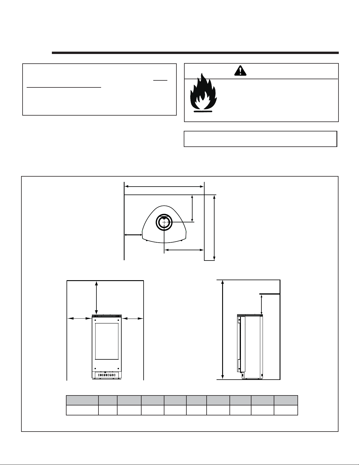
A. Selecting Appliance Location
When selecting a location for your gas stove it is important
to consider the required clearances to walls (see Figure
3.1).
B. Clearances to Combustibles
F
A
WARNING
Fire Risk
Provide adequate clearance:
• Around air openings
• To combustibles
• For service access
Locate gas stove away from traffi c areas.
NOTE: For actual gas stove dimensions refer to Section 12.
B
E
A
Centimeters
I
“A” measurement is from gas stove top, not side.
Alcove
G
A
D
AB C DEFGH I
15.2 25.7 30.8 137.2 91.4 78.1 33.7 33.7 39.4
H
Figure 3.1
6 Heat & Glo • VRTIKL-CE • 7031-292 Rev E • 12/07
Page 7
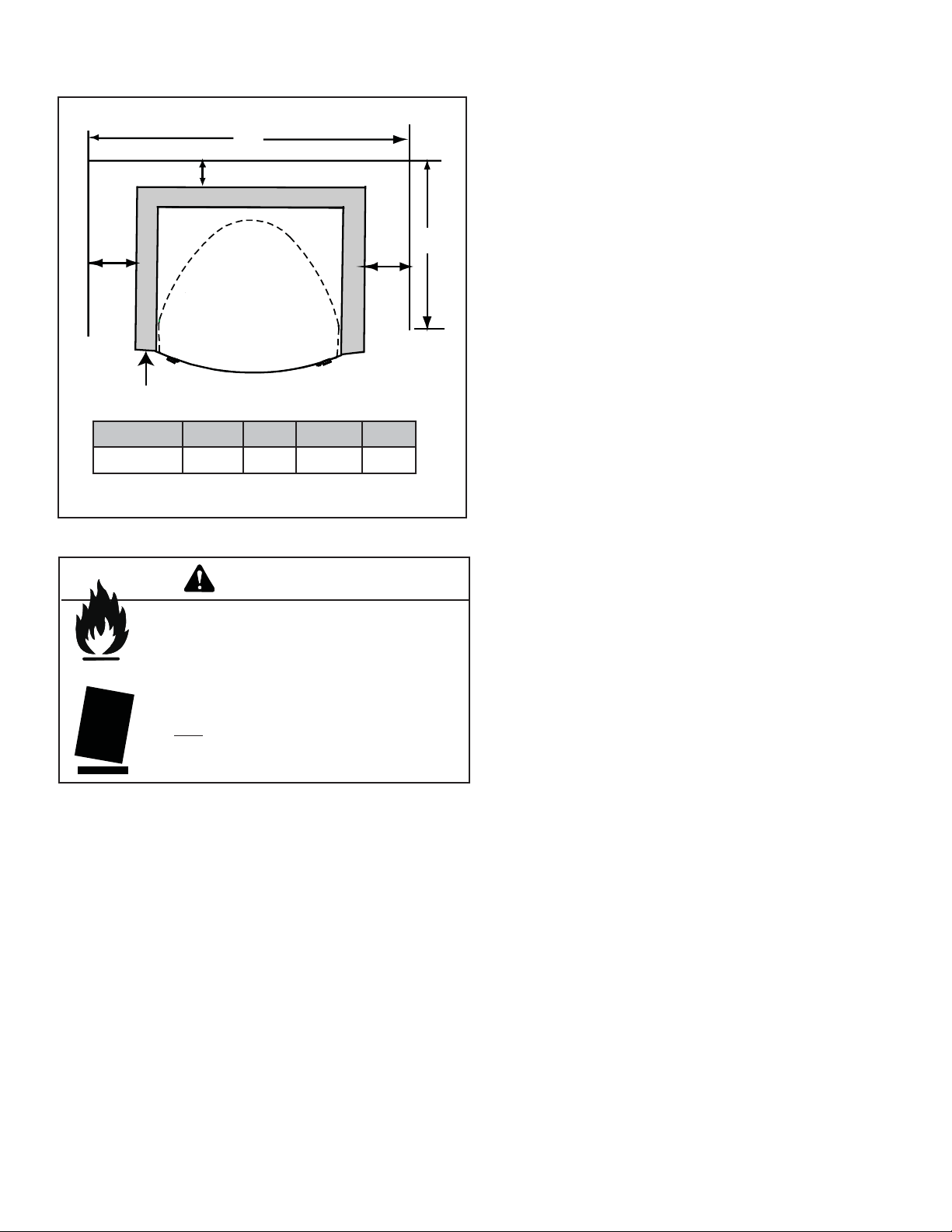
C. Optional Stone Surround Installed
C
B
D
A
Centimeters
Figure 3.1
A
ABC D
8.3 10.2 78.1 91.4
WARNING
Fire Risk.
Odor Risk.
Tipping Risk
• Install gas stove on a stable, level platform/
fl oor strong enough to support gas stove
without tipping.
• USE wood fl ooring, ceramic tile, brick hearth
or high pressure laminate fl ooring applied
directly over the sub-fl ooring material.
7Heat & Glo • VRTIKL-CE • 7031-292 Rev E • 12/07
Page 8
Termination Locations
4
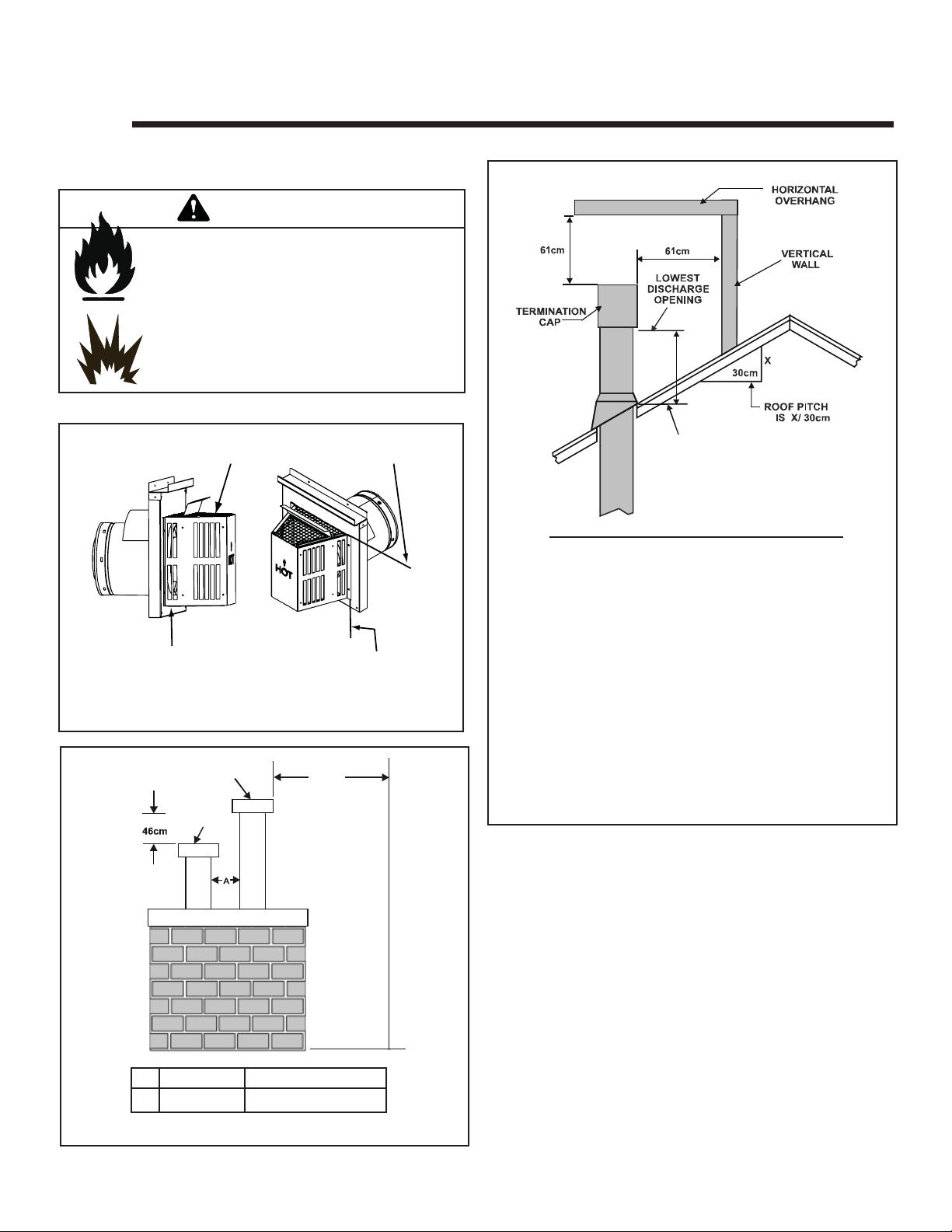
A. Flue Termination Minimum Clearances
WARNING
Fire Risk.
Explosion Risk.
Maintain fl ue clearance to combustibles
as specifi ed.
• Do not pack air space with insulation or
other materials.
Failure to keep insulation or other materials
away from fl ue pipe may cause fi re.
Measure vertical clearances from this surface.
Measure horizontal clearances from this surface.
(See Figure 4.4 for specifi c clearances.)
Figure 4.1 Termination Clearances
GAS, W OOD OR FUEL
OIL TERMINATION
(MINIMUM) TO
PERPENDICULAR
GAS
TERMINATION
WALL
(GAS ONLY)
61cm
H (MIN.) - MINIMUM HEIGHT FROM ROOF
TO LOWEST DISCHARGE OPENING
Roof Pitch H (Min.) M
Flat to 6/12..............................................................30*
Over 6/12 to 7/12 ....................................................38*
Over 7/12 to 8/12 ....................................................46*
Over 8/12 to 9/12 ....................................................61*
Over 9/12 to 10/12 ..................................................76
Over 10/12 to 11/12 ................................................99
Over 11/12 to 12/12 .............................................1.22
Over 12/12 to 14/12 .............................................1.52
Over 14/12 to 16/12 .............................................1.83
Over 16/12 to 18/12 .............................................2.13
Over 18/12 to 20/12 .............................................2.29
Over 20/12 to 21/12 .............................................2.44
*.91M minimum in snow regions
Figure 4.3 Minimum Height from Roof to Lowest Discharge
Opening
Figure 4.3 specifi es minimum fl ue heights for various
pitched roofs.
Gas Termination Wood & Fuel Oil Termination
15 cm 51 cm
A
Figure 4.2 Multiple Vertical Termination
8 Heat & Glo • VRTIKL-CE • 7031-292 Rev E • 12/07
Page 9
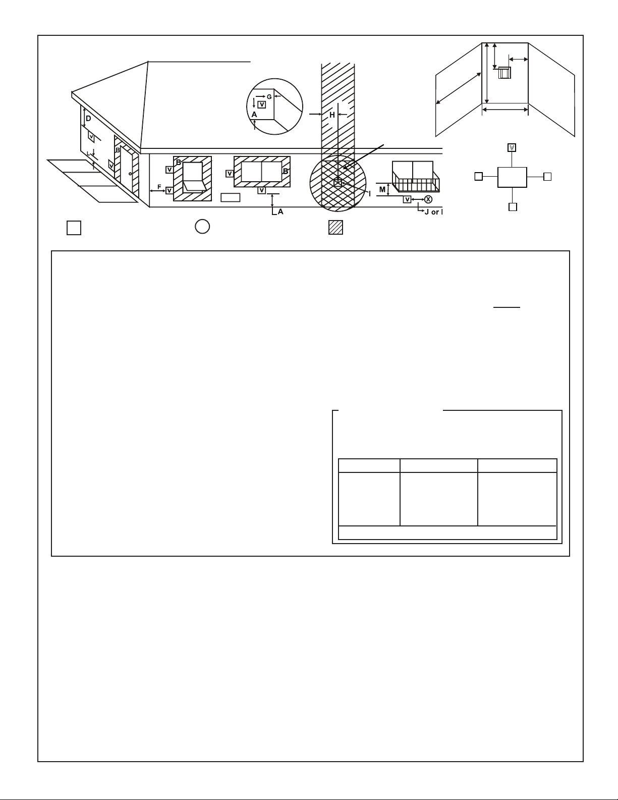
R
M
P
Q
(See Note 2)
N
= VENT TERMINAL
V
X
= AIR SUPPLY INLET
A = 31 cm ....................clearances above grade, veranda,
(See Note 1)
porch, deck or balcony
B = 31 cm ....................clearances to window or door
that may be opened, or to permanently closed window. (Glass)
D* = 31 cm ....................vertical clearance to unventilated
soffi t or to ventilated soffi t located
above the terminal
76 cm .....................for vinyl clad soffi ts and below
electrical service
F = 23 cm ...................clearance to outside corner
G = 15 cm ....................clearance to inside corner
H = 91 cm ....................not to be installed above a gas
meter/regulator assembly within 90
cm horizontally from the center-line
of the regulator
I = 1.8 M .....................clearance to gas service regulator
vent outlet
J = 31 cm ......................clearance to non-mechanical
air supply inlet to building or the
combustion air inlet to any other
gas stove
See Notes 3 & 4
V
S
V
T
Electrical
Service
D*
V
S
V
= AREA WHERE TERMINAL IS NOT PERMITTED
K = 1.8 M .......................clearance to a mechanical
(powered) air supply inlet
L** = 2.1 M .......................clearance above paved
(See Note 1)
sidewalk or a paved driveway
located on public property
M*** = 46 cm ......................clearance under veranda, porch,
deck, balcony or overhang
1.1 M ......................vinyl
S = 15 cm .......................clearance from sides of elec-
(See Note 5)
trical service
T = 31 cm ........................clearance above electrical
(See Note 5)
service
Alcove Applications
N = 15 cm .....................non-vinyl sidewalls
31 cm .....................vinyl sidewalls
P = 2.4 M
Q
MIN
1 cap .91 M 2 x Q
2 caps 1.8 M 1 x Q
3 caps 2.7 M 2/3 x Q
4 caps 3.7 M 1/2 x Q
Q
= # termination caps x 3 R
MIN
= (2 / # termination caps) x Q
MAX
R
MAX
ACTUAL
ACTUAL
ACTUAL
ACTUAL
ACTUAL
** a fl ue shall not terminate directly above a sidewalk or paved driveway
which is located between two single family dwellings and serves both
dwellings.
*** only permitted if veranda, porch, deck or balcony is fully open on a
minimum of 2 sides beneath the fl oor, or meets Note 2.
NOTE 1: On private property where termination is less than 7 feet above
a sidewalk, driveway, deck, porch, veranda or balcony, use of a listed cap
shield is suggested. (See fl ue components page)
NOTE 2: Termination in an alcove space (spaces open only on one side
and with an overhang) are permitted with the dimensions specifi ed for vinyl
or non-vinyl siding and soffi ts. 1. There must be 2.7M minimum between
termination caps. 2. All mechanical air intakes within 3M of a termination
cap must be a minimum of 2.7M below the termination cap. 3. All gravity
air intakes within 2.7M of a termination cap must be a minimum of .31M
foot below the termination cap.
Figure 4.4 Minimum Clearances for Termination
NOTE 3: Local codes or regulations may require different
clearances.
NOTE 4: Termination caps may be hot. Consider their proximity to
doors or other traffi c areas.
NOTE 5: Location of the fl ue termination must not interfere with
access to the electrical service.
Heat & Glo assumes no responsibility for the improper performance
of the gas stove when the fl ueing system does not meet these
requirements.
9Heat & Glo • VRTIKL-CE • 7031-292 Rev E • 12/07
Page 10
5
Flue Information
A. Flue Components
These models are approved to use Simpson Dura-Vent or
Hearth & Home Technologies series pipes, components and
termination. Approved components are labeled for identifi ca-
tion. This pipe is tested and listed as an approved component of the stove.
DO NOT USE FIELD-FABRICATED FLUE COMPONENTS.
Refer to the flue manufacturer’s instructions.
This product is approved to be flued either horizontally,
through the side wall or vertically through t he roof. You may
flue through a Class A or masonr y chimney if an approved
adapter is used.
This gas stove is a balanced fl ue gas stove. All combus-
tion air must come directly from the outside of the building.
The fl ue pipe for this unit consists of an inner and an outer
pipe. The inner pipe carries the gas stove exhaust out of the
system, and the outer pipe brings fresh combustion air into
the gas stove.
• A round support box/wall thimble or heat shield is
required when the fl ueing passes through a combus-
tible wall.
• A support box or ceiling fi restop is required when the
fl ueing passes through a combustible ceiling.
• Roof fl ashing and a storm collar are required when fl ue-
ing passes through the roof.
• Follow instructions provided with the fl ueing for installa-
tion of these items.
B. Use of Elbows
CAUTION
ALL fl ue confi guration specifi cations MUST be followed.
• This product is tested and listed to these
specifi cations.
• Appliance performance will suffer if specifi cations are
not followed.
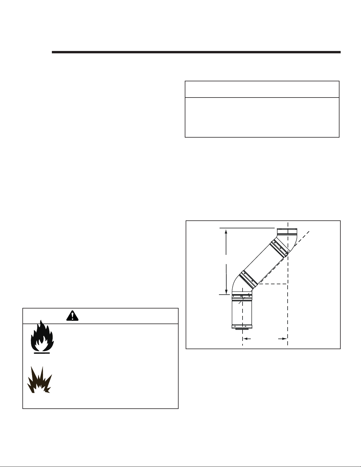
Diagonal runs have both vertical and horizontal flue aspects
when calculating the effects. Use the rise for the vertical
aspect and the run for the horizontal aspect. (See Figure
5.1.)
Two 45° elbows may be used in place of one 90° elbow. On
45° runs, one foot of diagonal is equal to 21.6 cm horizontal run and 21.6 cm vertical run. A length of straight pipe is
allowed between two elbows. (See Figure 5.1.)
Vertical
30.5 cm
21.6 cm
21.6 cm
WARNING
Fire Hazard.
Explosion Risk.
Asphyxiation Risk.
Do NOT connect this gas gas stove to a chimney
fl ue serving a separate solid-fuel or gas burning
gas stove.
• Flue this gas stove directly outside.
• Use separate fl ue system for this gas stove.
May impair safe operation of this gas stove or
other gas stoves connected to the fl ue.
10 Heat & Glo • VRTIKL-CE • 7031-292 Rev E • 12/07
Figure 5.1
C. Measuring Standards
Vertical and horizontal measurements were made using the
following standards.
• Pipe measurements are from center line to center line.
• Horizontal terminations are measured to the outside of
the mounting surface (fl ange of termination cap). See
Figure 4.1 on page 8.
• Horizontal pipe should be installed level with no rise.
Horizontal
Page 11
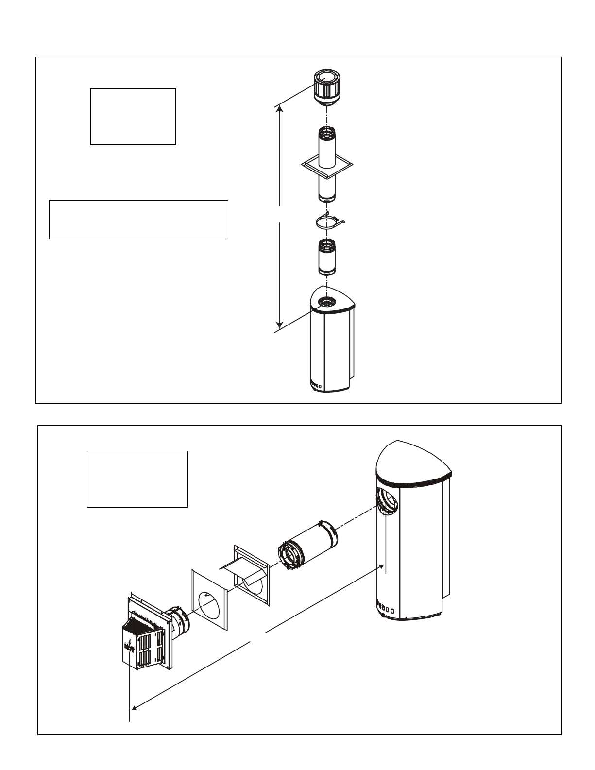
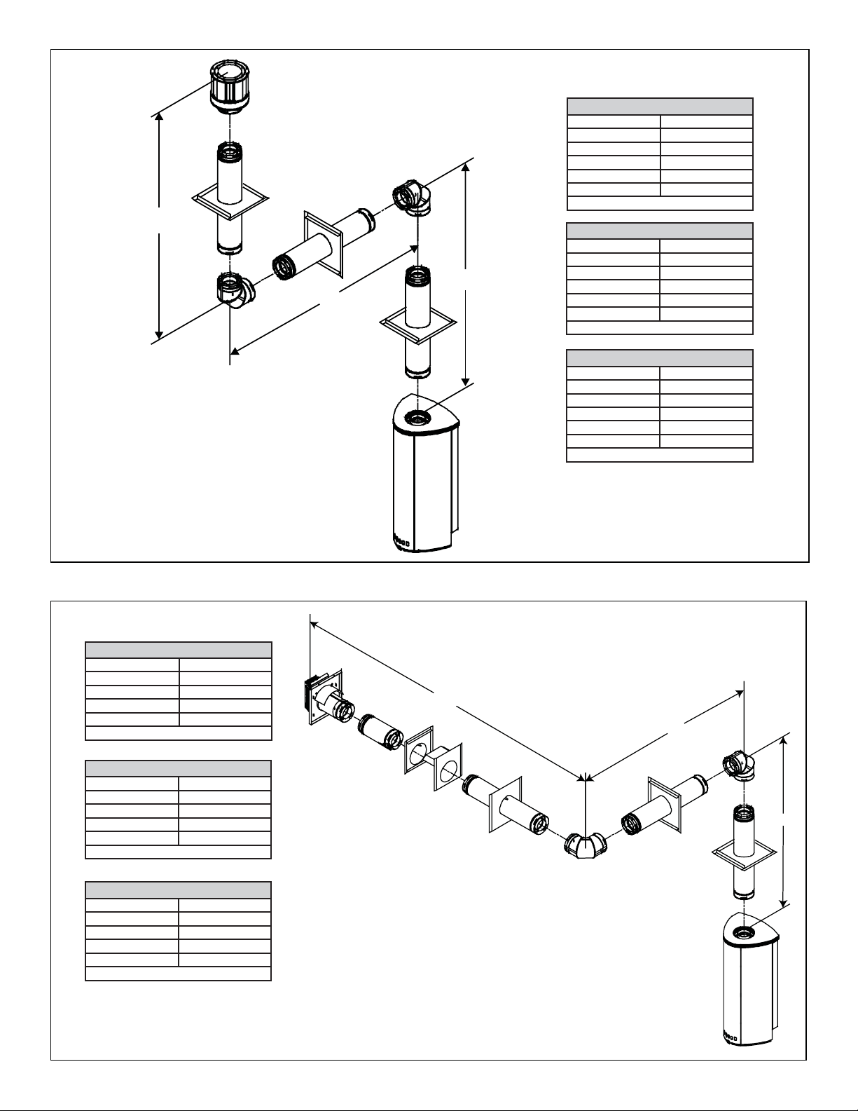
D. Flueing Diagrams
STRAIGHT UP
VERTICAL FLUE
V
11.8M Maximum
For Natural, Propane and Butane Gases.
Note: For this type of installation, the vertical
fl ue restrictor must be added. See section H
for instructions.
Figure 5.2
STRAIGHT OUT
HORIZONTAL FLUE
H
61cm Maximum
V
For Natural, Propane and Butane Gases.
Figure 5.3
H
11Heat & Glo • VRTIKL-CE • 7031-292 Rev E • 12/07
Page 12
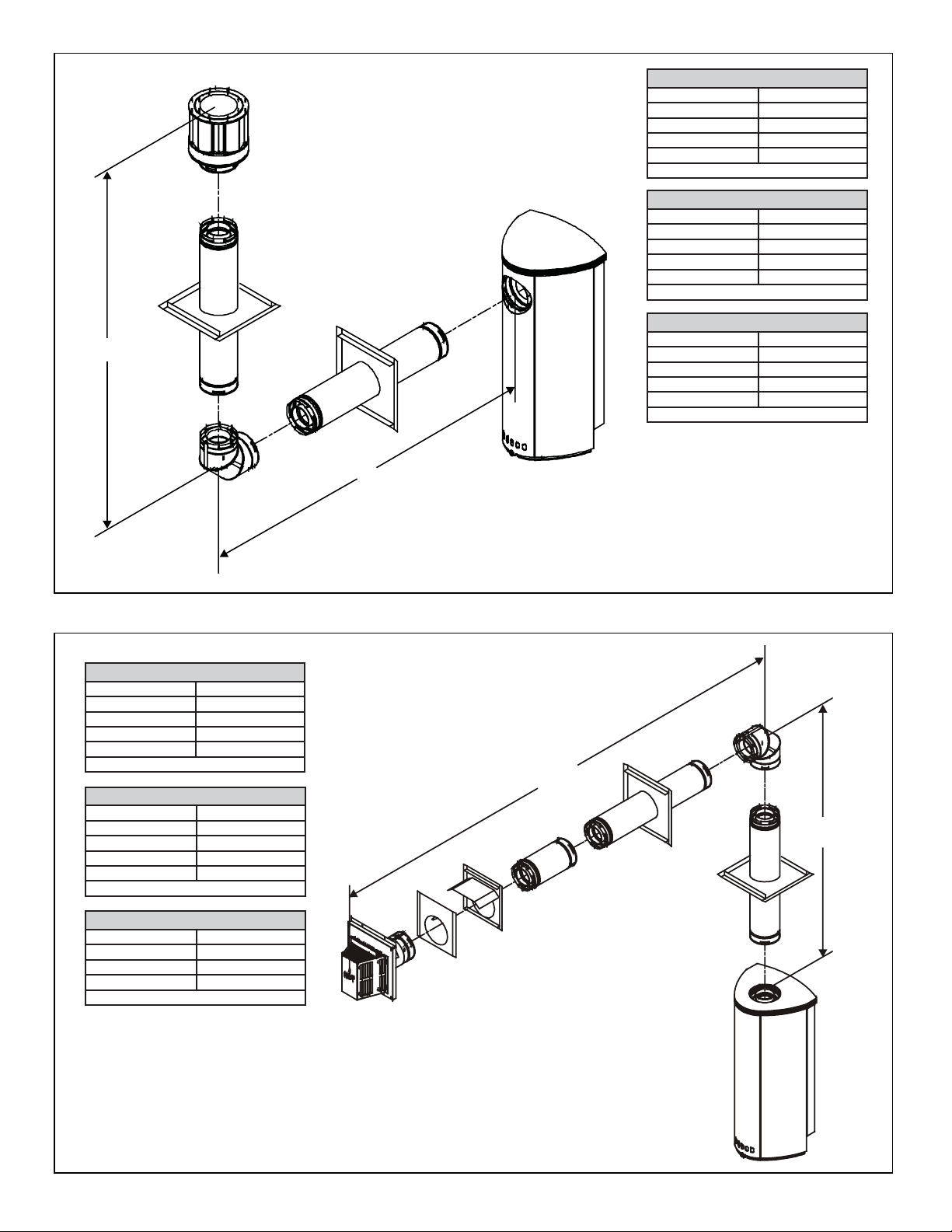
Natural Gas • One 900 Elbow System
V Minimum H Maximum
46 cm 1.3 M
92 cm 2.7 M
1.4 M 4.1 M
1.8 M 5.0 M
V+H = Max 11.6 M H Max = 5.0 M
Propane • One 900 Elbow System
V Minimum H Maximum
46 cm 92 cm
92 cm 1.8 M
1.4 M 2.8 M
1.8 M 3.6 M
V+H = Max 11.6 M H Max = 3.6 M
Butane • One 900 Elbow System
V
H
V Minimum H Maximum
46 cm 46 cm
92 cm 92 cm
1.4 M 1.4 M
1.8 M 1.8 M
V+H = Max 10 M H Max = 1.8 M
Figure 5.4
Natural Gas • One 900 Elbow System
V Minimum H Maximum
46 cm 1.3 M
92 cm 2.7 M
1.4 M 4.1M
1.8 M 5.0 M
V+H = Max 11 M H Max = 5.0 M
Propane • One 900 Elbow System
V Minimum H Maximum
46 cm 92 cm
92 cm 1.8 M
1.4 M 2.8 M
1.8 M 3.6 M
V+H = Max 11 M H Max = 3.6 M
Butane • One 900 Elbow System
V Minimum H Maximum
1.22 M 92 cm
1.4 M 1.4 M
1.8 M 1.8 M
V+H = Max 10 M H Max = 1.8 M
H
V
Figure 5.5
12 Heat & Glo • VRTIKL-CE • 7031-292 Rev E • 12/07
Page 13
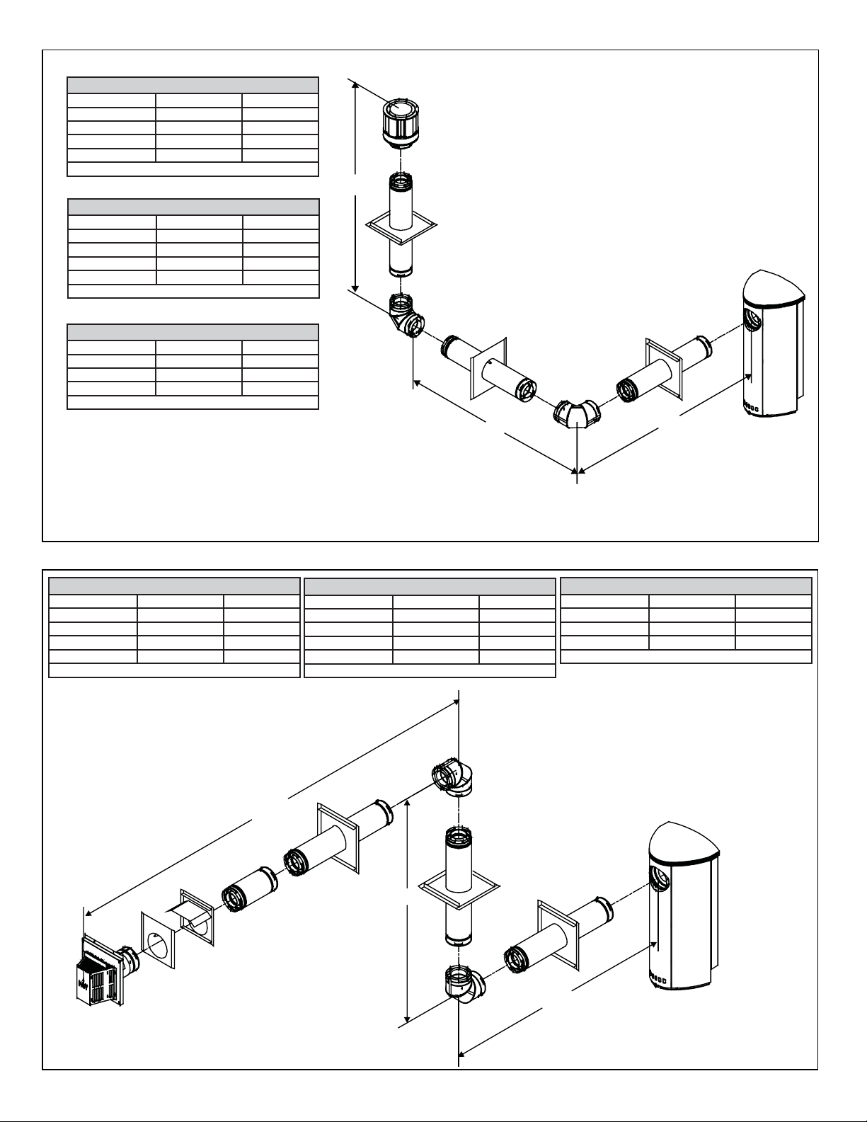
Natural Gas • Two 900 Elbows System
V Min. H1 Max. H1 + H2 Max.
46 cm 55 cm 1.1 M
92 cm 1.1 M 2.2 M
1.4 M 1.7 M 3.5 M
1.8 M 2.2 M 4.5 M
V+H1+H2 = Max 11.0M H1 Max = 2.2M H1+H2 = Max 4.5M
Propane • Two 900 Elbows System
V Min. H1 Max. H1 + H2 Max.
46 cm 39 cm 69 cm
92 cm 75 cm 1.3 M
1.4 M 1.1 M 2.1 M
1.8 M 1.5 M 2.7 M
V+H1+H2 = Max 10.6M H1 Max = 1.5M H1+H2 = Max 2.7M
Butane • Two 900 Elbows System
V Min. H1 Max. H1 + H2 Max.
1.22 M 48 cm 61 cm
1.4 M .5 M .7 M
1.8 M .7 M .9 M
V+H1+H2 = Max 10M H1 Max = .7M H1+H2 = Max .9M
V
H2
H1
Figure 5.6
Natural Gas • Two 900 Elbows System
V Min. H1 Max. H1 + H2 Max.
46 cm 55 cm 1.1 M
92 cm 1.1 M 2.3 M
1.4 M 1.7 M 3.5 M
1.8 M 2.2 M 4.5 M
V+H1+H2 = Max 10M H1 Max = 2.2M H1+H2 = Max 4.5M
H2
Propane • Two 900 Elbows System
V Min. H1 Max. H1 + H2 Max.
46 cm 39 cm 69 cm
92 cm 75 cm 1.3 M
1.4 M 1.1 M 2.1 M
1.8 M 1.5 M 2.7 M
V+H1+H2 = Max 10M H1 Max = 1.5M H1+H2 = Max 2.7M
V
Butane • Two 900 Elbows System
V Min. H1 Max. H1 + H2 Max.
1.22 M 48 cm 61 cm
1.4 M .5 M .7 M
1.8 M .7 M .9 M
V+H1+H2 = Max 10M H1 Max = .7 H1+H2 = Max .9M
Figure 5.7
H1
13Heat & Glo • VRTIKL-CE • 7031-292 Rev E • 12/07
Page 14
V
Natural Gas • Two 900 Elbows System
V1 Min. H Max.
31 cm 93 cm
61 cm 1.8 M
91 cm 2.7 M
1.2 M 3.6 M
1.5 M 4.5 M
V1+V2+H = Max 11.4M H Max = 4.5M
2
V1
H
Propane • Two 900 Elbows System
V1 Min. H Max.
31 cm 62 cm
61 cm 1.2 M
91 cm 1.8 M
1.2 M 2.4 M
1.5 M 3.0 M
V1+V2+H = Max 11.4M H Max = 3.0M
Butane • Two 900 Elbows System
V1 Min. H Max.
31 cm 31 cm
61 cm 61 cm
92 cm 92 cm
1.2 M 1.2 M
1.5 M 1.5 M
V1+V2+H = Max 10 M H Max = 1.0 M
Figure 5.8
Natural Gas • Two 900 Elbows System
V Min. H1+H2 Max.
61 cm 1.6 M
91 cm 2.4 M
1.2 M 3.2 M
1.5 M 4.0 M
V+H1+H2 = Max 11.4M H1+H2 = Max 4.0M
Propane • Two 900 Elbows System
V Min. H1+H2 Max.
61 cm 1.0 M
91 cm 1.5 M
1.2 M 2.0 M
1.5 M 2.6 M
V+H1+H2 = Max 11.4M H1+H2 = Max 2.6M
Butane • Two 900 Elbows System
V1 Min. H1+H2 Max.
61 cm 42 cm
92 cm 64 cm
1.2 M .8 M
1.5 M 1.0 M
V+H1+H2 = Max 10 M H1+H2 = Max 1.5 M
H2
H1
V
Figure 5.9
14 Heat & Glo • VRTIKL-CE • 7031-292 Rev E • 12/07
Page 15

V
Natural Gas • Three 900 Elbows System
V1 Min. H1 Max. H1 + H2 Max.
46 cm 55 cm 1.1 M
92 cm 1.1 M 2.3 M
1.4 M 1.7 M 3.5 M
1.8 M 2.2 M 4.5 M
V1+V2+H1+H2=Max11M H1 Max=2.2M H1+H2=Max 4.5M
Propane • Three 900 Elbows System
V1 Min. H1 Max. H1 + H2 Max.
46 cm 34 cm 69 cm
92 cm 65 cm 1.3 M
1.4 M 1.0 M 2.1 M
1.8 M 1.8 M 2.7 M
V1+V2+H1+H2=Max 11M H1 Max=1.8M H1+H2=Max 2.7M
2
Butane • Three 900 Elbows System
V1 Min. H1 Max. H1 + H2 Max.
46 cm 14 cm 32 cm
92 cm 23 cm 64 cm
1.4 M 35 cm .8 M
1.8 M 45 cm 1.0 M
V1+V2+H1+H2=Max 10M H1 Max=45cm H1+H2=Max 1.0M
H2
H1
V1
Figure 5.10
Natural Gas • Three 900 Elbows System
V1 Min. H1 Max. H1 + H2 Max.
46 cm 55 cm 1.0 M
92 cm 1.1 M 2.0 M
1.4 M 1.7 M 3.0 M
1.8 M 2.2 M 3.9 M
V1+V2+H1+H2=Max 11M H1 Max=2.2M H1+H2=Max 3.9M
V2
H2
V1
Propane • Three 900 Elbows System
V1 Min. H1 Max. H1 + H2 Max.
46 cm 34 cm 55 cm
92 cm 65 cm 1.1 M
1.4 M 1.0 M 1.6 M
1.8 M 1.8 M 2.1 M
V1+V2+H1+H2=Max 10M H1 Max=1.8M H1+H2=Max 2.1M
Butane • Three 900 Elbows System
V1 Min. H1 Max. H1 + H2 Max.
64 cm 16 cm 32 cm
92 cm 23 cm 36 cm
1.4 M 35 cm .7 M
1.8 M 45 cm .9 M
V1+V2+H1+H2=Max 10M H1 Max=45 cm H1+H2=Max .9M
Figure 5.11
H1
15Heat & Glo • VRTIKL-CE • 7031-292 Rev E • 12/07
Page 16

E. Horizontal Termination
C
90 DEGREE
ELBOW
PIPE LENGTH
WALL THIMBLE
COVER
PIPE LENGTH
WALL THIMBLE
TERMINATION CAP
Note: Female ends of balanced flue pipe/elbows are
designed to slide straight onto the male ends of adjacent
pipes by orienting the pipe indentations so they match and
slide into the entry slots on the male ends, see Figure 5.13.
Push the pipe sections completely together, then twist-lock
one section clockwise approximately one-quarter turn, until
the two sections are fully locked. The female locking lugs
may not be visible from the outside. They may be located by
examining the inside of the female ends.
Female Locking Lugs
Male Locking Lugs
Figure 5.13
WARNING
Fire Risk.
Explosion Risk.
Combustion Fume Risk.
Use fl ue run supports per installation instructions.
Connect fl ue sections per installation instructions.
• Maintain all clearances to combustibles.
• Do NOT allow fl ue to sag below connection
point to gas stove.
Improper support may allow fl ue to sag or separate.
ENTER
LINE
Figure 5.12
6 in.
4 in.
CENTER LINE
Step 1.
Determine the desired location of the gas stove. Check to
ensure that wall studs or roof rafters are not in the way when
the flue system is being planned. If this is the case, you may
want to adjust the location of the gas stove.
Step 3.
For installations using a round support box/wall thimble
(check pipe manufacturer's instructions), mark the wall for
a 25.4 cm x 25.4 cm square hole. The center of the square
hole should line up with the center line of the horizontal
WARNING
Fire Hazard.
Exhaust Fume Risk.
• Ensure fl ue components are locked together correctly.
• Pipe may separate if not properly joined.
Impaired Performance of Appliance.
pipe, as shown in Figure 5.12. Cut and frame the hole in
the exterior wall where the flue will be terminated. If the wall
being penetrated is constructed of noncombustible material,
i.e. masonry block or concrete, a 17.8 cm diameter hole is
acceptable.
Step 4.
Position the horizontal termination cap in the center of the
Step 2.
Balanced flue pipe is designed with a locking connection. To
connect the flue system to the gas stove flue outlet, a twistlock adapter is built into the gas stove at the factory. Wall
thickness may vary. Remember to include wall thickness in
25.4cm x 25.4cm square hole and run a bead of non-hardening mastic around its outside edges, to make a seal between
it and the wall. Attach termination cap to the exterior wall
with the four wood screws provided. The arrow on the flue
cap should be pointing up.
minimum clearances when figuring flueing lengths for your
installation needs.
16 Heat & Glo • VRTIKL-CE • 7031-292 Rev E • 12/07
Page 17

F. Slim Line Wall Thimble
BEFORE YOU BEGIN:
Review the fl ueing confi gurations in Figures A, B and C on
the next page.
1. Assembling Slim Line Trim Ring and Heat Shield
Figure 5.14
Lay the trim ring on fl at surface and bend up the six welded
brackets into a 90 degree position. The brackets along the
outer edge of the ring are for locating the ring in the center
of the hole.
Figure 5.16
Attach the heat shield to the trim ring with the four screws
provided. Screws go through the heat shield and into the
brackets on the trim ring.
2. Installing Slim Line Trim Ring and Heat Shield
Measure from the fl oor to the center of the fl ue pipe. Cut
out a 25.4 cm hole in the wall. Hold the trim ring/heat shield
assembly in place and put a mark on the shield with a black
marker where it protrudes through the exterior wall. Figure
A on the next page.
Use that mark as a guide to trim off excess heat shield with
a pair of sheet metal shears.
Figure 5.15
The heat shield is shipped fl at and must be hand bent into a
half circle before attaching it to the trim ring. Bend the heat
shield as shown.
CAUTION
Sharp Edges
• Wear protective gloves
and safety glasses during
installation.
Figure 5.17
When installing the trim ring/heat shield assembly make
sure the trim ring is centered in the hole and that the shield
is above the pipe. There must be a minimum of 2 cm minimum clearance maintained to combustibles from the top of
the heat shield.
Ensure that framing on the inside of the wall is a minimum
inner framing diameter of 25.4 cm x 25.4 cm.
The four trim ring mounting screws provided should be
replaced with appropriate fasteners for stucco, brick, concrete, or other types of sidings.
17Heat & Glo • VRTIKL-CE • 7031-292 Rev E • 12/07
Page 18

FIG. A 90 DEGREE ELBOW
C
Place mark where protrudes through
exterior wall to cut off excess.
O
90 ELBOW
CENTER
LINE
USE HEAT SHIELD / WALL THIMBLE
PIPE
LENGTH
TRIM
RING
PIPE LENGTH
FIG. B MINIMUM CLEARANCE
INTERIOR WALL
51mm clearance
from rear of stove
ENTER LINE
Figure 5.18
MINIMUM OF 152 mm
OF PIPE THROUGH THE WALL
WALL THIMBLE
HEAT SHIELD OVER
TOP HALF OF PIPE
TRIM RING
18 Heat & Glo • VRTIKL-CE • 7031-292 Rev E • 12/07
Page 19

G. Vertical Termination
1. Balance Flue Pipe
STORM COLLAR
VERTICAL
TERMINATION CAP
FLASHING
FIRESTOP
SUPPORT
BOX
PIPE LENGTH
On vertical terminations use only Part #SLK-991DA
Figure 5.19
Step 1.
Check the installation instructions for required 2.5 cm clearances (air space) to combustibles when passing through
ceilings, walls, roofs, enclosures, attic rafters, or other
nearby combustible surfaces. (See Figure 5.14). Check the
instructions for maximum vertical rise of the flueing system,
and any maximum horizontal offset limitations. All offsets
must fall within the set parameters of the flue charts (Figure
5.2) located on pages 11-15.
11.8M
MAXIMUM
Figure 5.20
Step 2.
Set the gas gas stove in its desired location. Drop a plumb
bob down from the ceiling to the position of the gas stove
flue exit, and mark the location where the flue will penetrate
the ceiling. Drill a small hole at this point. Next, drop a plumb
bob from the roof to the hole previously drilled in the ceiling,
and mark the spot where the flue will penetrate the roof.
Determine if ceiling joists, roof rafters, or other framing will
obstruct the flueing system. You may wish to relocate the
gas stove, or to offset, as shown in Figure 5.21 to avoid
cutting load bearing members.
NOTE: Maximum vertical rise allowable is 11.8 M, Figure
5.2.
WARNING
Fire Risk.
Explosion Risk.
Maintain fl ue clearance to combustibles as speci-
fi ed.
• Do not pack air space with insulation or other
materials.
Failure to keep insulation or other materials away
from fl ue pipe may cause fi re.
METAL STRAP
CONNECTED TO
WALL STRAP
WALL
STRAP
TWO 45 DEGREE
ELBOWS
Figure 5.21
19Heat & Glo • VRTIKL-CE • 7031-292 Rev E • 12/07
Page 20

Step 3.
To install the round support box/wall thimble cover in a flat
ceiling, cut a 25.4cm square hole in the ceiling, centered
on the hole drilled in Step 2. Frame the hole as shown in
Figure 5.22.
CEILING JOISTS
FRAMING
SHINGLES OVERLAP ON
TOP EDGE OF FLASHING
ROUND CEILING
SUPPORT BOX/WALL
THIMBLE COVER
4 cm LONG
WOOD SCREWS
Figure 5.22
Step 4.
Assemble the desired lengths of pipe and elbows necessary
to reach from the gas stove up through the round support
box. Ensure that all pipe and elbow connections are in their
fully twist-locked position. Assemble as instructed.
Step 5.
Cut a hole in the roof centered on the small drill hole placed in
the roof in Step 2. The hole should be of sufficient size to meet
the minimum requirements for clearance to combustibles, as
specified. Continue to assemble lengths of pipe and elbows
necessary to reach from the ceiling support box/wall thimble
up through the roof line. Galvanized pipe and elbows may
be utilized in the attic, as well as above the roofline. The
galvanized finish is desirable above the roofline, due to its
higher corrosion resistance (compared to black pipe).
CAP AND STORM COLLAR NOT S HOWN FOR CLARITY
Figure 5.23
Step 7.
Continue to assemble pipe sections until the height of the
flue (before adding the termination cap) meets the minimum
local code requirements. Note that for steep roof pitches, the
flue height must be increased. See Roof Pitch Table (Figure
4.3). In high wind conditions, nearby trees adjoining rooflines,
steep pitched roofs, and other similar factors can result in
poor draft, or down drafting. In these cases increasing the
flue height or switching to the high wind termination cap may
solve this problem.
Step 8.
Slip the storm collar over the pipe, and push it down to the
top of the flashing (Figure 5.24). Use non-hardening sealant
above and below the joint between the storm collar and the
pipe.
SECURE FLASHING WITH
NON-HARDENING SEALANT
AND ROOFING NAILS
NOTE:
(1) If an offset is necessary in the attic to avoid obstructions,
it is important to support the flue pipe every 91.4cm to
avoid excessive stress on the elbows, and possible
separation. Wall straps are available for this purpose,
Figure 5.10, page 15.
(2) Whenever possible, use 45° elbows, instead of 90°
elbows. The 45° elbow offers less restriction to the flow
of flue gases and intake air.
Step 6.
Slip the flashing over the pipe section(s) protruding through
the roof. Secure the base of the flashing to the roof with
roofing nails. Ensure the roofing material overlaps the top
edge of the flashing as shown in Figure 5.23. Verify that the
chimney is the required height above the roof. See roof pitch
table, Figure 4.3.
20 Heat & Glo • VRTIKL-CE • 7031-292 Rev E • 12/07
Figure 5.24
Page 21

Step 9.
Twist-lock the flue cap and seal.
Note: For multi-story vertical installations, a ceiling firestop
is required at the second floor, and any subsequent floors
(Figure 5.25). The opening should be framed to 25.4cm x
25.4cm inside dimensions, in the same manner as shown in
Figure 5.22.
NAILS
CEILING FIRESTOP
MIN. 25.4 cm
CLEARANCE
MIN. 25.4 cm
CLEARANCE
MIN. 25.4 cm
CLEARANCE
H. Vertical Flue Restrictor
If the fireplace installation requires a vertical flue off the
top of the unit with no horizontal flue or elbows, the vertical
flue restrictor must be added. Reinstall heat shield when
completed. See Figure 4.25.
FLUE
RESTRICTOR
PLATE
HEAT SHIELD
Figure 5.26
Figure 5.25
MIN. 25.4 cm
CLEARANCE
WARNING
Fire Risk.
Explosion Risk.
•
Any occupied areas above the first floor, including
closets and storage spaces, which the vertical flue
passed through must be enclosed. The enclosure
may be framed and sheetrocked with standard
construction materials; however, refer to these
installation instructions for the minimum allowable
clearance between the outside of the flue pipe and
the combustible surfaces of the enclosure. Do not
fill any of the required air space with insulation.
21Heat & Glo • VRTIKL-CE • 7031-292 Rev E • 12/07
Page 22

6
Gas Information
A. Gas Pressure Requirements
Pressure requirements for VRTIKL-CE Stoves are shown in
Table 1 below.
Two taps are provided on the right hand side of the gas control
for a test gauge connection to measure the inlet and outlet
pressures. See Section 10: Maintaining and Servicing the
Appliance.
The stove and its individual shut-off valve must be disconnected
from the gas supply piping system during any pressure testing
of the system at test pressures in excess of 60 mbar.
If the stove must be isolated from the gas supply piping
system by closing an individual shut-off valve, it must be of
the handle-less type.
WARNING
Fire Risk
Explosion Risk
High pressure will damage valve.
• Disconnect gas supply piping BEFORE
pressure testing gas line at test pressures
above 60 mbar.
• Close the manual shutoff valve BEFORE
pressure testing gas line at test pressures
equal to or less than 60 mbar.
B. Gas Connection
Note: Have the gas supply line installed in accordance with
local building codes by a qualifi ed installer approved
and/or licensed as required by the locality.
Note: Before the fi rst fi ring of the stove, the gas supply
line should be purged of any trapped air.
Note: Consult local building regulations to properly size
the gas supply line leading to the (Rp 1/2 in.) hook-up
at the unit.
Incoming gas line should be piped into the valve compartment
and connected to the ISO 7-Rp 1/2 (BSP Rp 1/2 ) threaded
gas inlet connection on the manual shutoff valve.
Leak test all gas line points and the gas control valve prior to
and after starting the gas stove.
WARNING
CHECK FOR GAS LEAKS
Fire Risk
Explosion Risk
Asphyxiation Risk
• Check all fi ttings and connections.
• Do not use open fl ame.
• After the gas line installation is complete,
all connections must be tightened and
checked for leaks with a commercially
available, non-corrosive leak check
solution. Be sure to rinse off all leak check
solution following testing.
Fittings and connections may have loosened
during shipping and handling.
Table 1
Natural Gas
(G20)
Inlet Pressure 20mbar 37 or 50mbar 30 or 50mbar 25mbar
Manifold Pressure 4-8.4mbar 15.7-25mbar 15.7-25mbar 4-8.4mbar
3
Gas Rate .72
Max.Input (NETCV) 6.9 kW 6.6 kW 5.8 kW 5.5 kW
Burner Injector DMS 39 DMS 53 DMS 55 DMS 39
Pilot Injector 51 30 30 51
22 Heat & Glo • VRTIKL-CE • 7031-292 Rev E • 12/07
m
/
h
.26
Propane
(G31)
3
m
/
h
.10
Butane
(G30)
3
m
/
h
Natural Gas
(G25)
.67 m3/
h
Page 23

Electrical Information
7
A. Ignition System Wiring
• This gas stove is equipped with an electronic ignition
system which operates on a 6 volt system.
• The batteries are located within the ignition module
which is located behind the glass door assembly . A wiring
diagram is shown in Figure 7.1.
• The battery pack requires four AA batteries (not included).
WARNING
Shock Risk
• Replace damaged wire with type 105° C rated wire.
• Wire must have high temperature insulation.
CAUTION
CAUTION
Battery polarity must be correct or module damage will
occur.
PILOT
IGNITION MODULE
6VDC
BATTERY PORT
(4 AA BATTERIES)
Label all wires prior to disconnection when servicing
controls. Wiring errors can cause improper and dangerous
operation. Verify proper operation after servicing.
FLAME SPARKER/
SENSOR
REMOTE
CONTROL
ANT.
VALVE
ON/OFF
WALL SWITCH
IGNITION
MODULE
(6V)
ON/OFF
SWITCH
Figure 7.1 Electronic Ignition Wiring Diagram
PILOT GAS LINE
CONNECTED TO
BACK OF VALVE
THERMOCOUPLE
BLOCK
(CONNECTED TO
BACK OF VALVE)
VALVE
23Heat & Glo • VRTIKL-CE • 7031-292 Rev E • 12/07
Page 24

8
ALLEN HEAD SCREWS
LEVELING
SCREWS
LAG BOLT
HOLE
Appliance Setup
A. Remove Shipping Materials
Remove shipping materials from inside or underneath the
fi rebox.
The gas line is shipped inside back panel. To access the gas
line remove the top plate from the gas stove. Remove and
retain the two Allen head screws that hold the back panel in
place. Replace panel when fi nished.
ALLEN HEAD SCREWS
Figure 8.1
C. Leveling and Bolting Down the Appliance
SECURING THE GAS STOVE
IS REQUIRED.
WARNING
Tipping Risk
• Install gas stove on a stable, level platform/
fl oor strong enough to support gas stove
without tipping.
• USE wood fl ooring, ceramic tile, brick hearth
or high pressure laminate fl ooring applied
directly over the sub-fl ooring material.
LEVELING
SCREWS
LAG BOLT
HOLE
B. Unbolting Appliance from the Pallet
The gas stove is bolted and screwed to the pallet for shipping. Use a 1/2 in. socket to remove the bolt in center of
bottom plate. Use a Phillips screwdriver to remove the two
screws in the front of the bottom plate and the two screws
holding the metal strap across the back of the gas stove.
Refer to Figure 8.2 for locations.
Figure 8.2
Figure 8.3
After unbolting the gas stove from the pallet, insert two 1/4
20 x 1-1/2 (or equivalent) counterscrews.
Using pliers, adjust the counterscrews to level the gas
stove.
24 Heat & Glo • VRTIKL-CE • 7031-292 Rev E • 12/07
Page 25

CLEARANCE
IINNER EXTENSION COLLAR
DV ADAPTER
ALLEN HEAD
SCREWS
HOLE
Figure 8.4
The manufacturer recommends securing the lag bolt from
the component bag in the center hole in the bottom plate
(clearance hole). This bolt will help to prevent tipping forward.
E. Top to Rear Flue Conversion
KIT CONTENTS: Top cover (without hole);
Back panel (with hole).
1. Remove the front door assembly by pulling bottom
of front away from gas stove and lifting it off of the
hooks on top of the gas stove. Set door aside.
ON TOP OF APPLIANCE:
2. Remove the top plate with hole and discard. (Figure 8.6)
Figure 8.5
Using pliers, adjust the counter screws to level the gas
stove.
D. Accessories
Install approved accessories per instructions included with
accessories. Refer to Section 12F for appropriate accessories.
WARNING
Shock or fi re risk.
Use ONLY optional accessories approved for
this gas stove.
• Using non-listed accessories voids
warranty.
• Using non-listed accessories may result in a
safety hazard.
• Only Hearth & Home T echnologies approved
accessories may be used safely.
Figure 8.6
3. Remove and retain the Allen head screws that hold
the solid back panel in place (Figure 8.8). Remove
and discard the solid back panel.
NNER EXTENSION COLLAR
DV ADAPTER
ALLEN HEAD
SCREWS
Figure 8.7
4. Remove the inner extension collar (Shown in Figure
8.7) and set aside.
5. Remove the four screws from the DV adapter collar
(Figure 8.7). Set aside DV adapter collar and
screws.
25Heat & Glo • VRTIKL-CE • 7031-292 Rev E • 12/07
Page 26

ON BACK OF APPLIANCE:
IINNER EXTENSION COLLAR
6. Remove the four screws from the cover plate on rear
of gas stove. Set cover plate aside. Retain screws.
(See Figure 8.8). Attach DV adapter collar in its
place. Install the inner extension collar.
NNER EXTENSION COLLAR
Figure 8.8
ON TOP OF APPLIANCE:
8. Install the new back panel (without hole) to the rear of
gas stove. Replace the Allen head screws removed
in Step 3 to hold the back panel in place.
9. Install the new top as shown in Figure 8.10.
Figure 8.10
7. Install the cover plate with gasket to the top of gas stove
with screws previously removed (Figure 8.9).
Figure 8.9
F. Installing the Baffl e
The baffl e is shipped wrapped, inside the fi rebox. Install
the baffl e with the embedded “T” side up, place it on top
of the brackets on the inside of the fi rebox, ensuring back
edge of baffl e makes contact with the back of the fi rebox.
Figure 8.11
26 Heat & Glo • VRTIKL-CE • 7031-292 Rev E • 12/07
Page 27

G. Positioning the Logs
While still breakable, the logs do not become fragile until
after the gas stove is burned and they have cured. After
curing, any handling must be done with care as breakage
can easily occur.
PLEASE NOTE: Logs have been designed to work specifically with the burner of this gas stove. Exact placement will ensure proper operation of your gas stove.
Figure 8.12
Figure 8.14
Locate log #2 over the pin in log #1 and into notch in log #1.
Lean the log back toward the left corner of the firebox.
H. Placing Mineral Wool
WARNING
Explosion Risk.
• Follow ember placement instructions in
manual.
• Do NOT place embers directly over
burner ports.
• Replace ember material annually.
Improperly placed embers interferes with proper burner
operation.
Figure 8.13
Place log #1 into the cradle in the burner. Lean the log back
towards right corner of firebox.
Figure 8.17
Apply 1.5 cm size pieces sparingly along ports as shown in
Figure 8.17. Do not block ports.
27Heat & Glo • VRTIKL-CE • 7031-292 Rev E • 12/07
Page 28

I. Front Door Glass Assembly Installation
J. Inner Glass Door Assembly Replacement
Remove the front door assembly by pulling bottom of front
away from gas stove and lifting it off of the hooks on top of
the gas stove (see Figure 8.15).
Refer to Figure 8.16: Position the four fl at 6 mm spacer
washers on the front door so that the four mounting screws
pass through them. Position the glass over the front door.
Install the four protective barrels into the glass and the four
nylon washers on top of the glass.
From inside the door front, pass the screws through to the
outside and thread on the caps until tight.
Turn the gas stove OFF and let it cool down before replacing
the inner glass door assembly.
With the front door assembly removed from the gas stove,
remove the inner glass door assembly by disengaging the
spring-loaded latches at the bottom of the gas stove and
lifting off of the two spring-loaded latches at the top of the
gas stove.
Replace with a new inner glass door assembly.
Figure 8.15
Cap and Barrel Fastener System
Nylon washer on back
and front of glassScrew
Protective barrel sleeve
through hole in the glass
Finishing Cap
Figure 8.17 Complete Assembly
CAUTION
Handle glass assembly with care.
• Inspect the gasket to ensure it is undamaged.
• Inspect the glass for cracks, chips or
scratches.
• Do NOT strike, slam or scratch glass.
• Do NOT operate gas stove with glass door
removed, cracked, broken or scratched.
• Replace glass assembly as a complete
assembly.
Back side of
front door
Figure 8.16
28 Heat & Glo • VRTIKL-CE • 7031-292 Rev E • 12/07
Page 29

9
Operating Instructions
A. Before Lighting Appliance
Read this entire manual prior to using the gas stove. Failure
to follow the instructions may result in property damage,
bodily injury, or even death.
• Remove all shipping materials from inside and/or underneath the fi rebox.
• Review proper placement of logs, mineral wool.
• Check the wiring.
• Check the baffl e adjustment.
• Ensure that there are no gas leaks.
• Ensure that the glass is sealed and in the proper position.
• Ensure that the fl ow of combustion and ventilation air is
not obstructed (front grilles and fl ue caps).
WARNING
Glass door must be in place when gas stove is
operating.
Risk of:
• Combustion Fumes
• Fire
Do NOT operate gas stove with glass door
removed.
• Open viewing glass for servicing only.
WARNING
HOT SURFACES!
Glass and other surfaces are hot during
operation AND cool down.
Hot glass will cause burns.
• DO NOT touch glass until it is cooled
• NEVER allow children to touch glass
• Keep children away
• CAREFULLY SUPERVISE children in same room as
fi replace.
• Alert children and adults to hazards of high temperatures.
High temperatures may ignite clothing or other
fl ammable materials.
• Keep clothing, furniture, draperies and other fl ammable
materials away.
This appliance has been supplied with an integral barrier
to prevent direct contact with the fi xed glass panel. DO
NOT operate the appliance with the barrier removed.
Contact your dealer if the barrier is not present or help is
needed to properly install one.
WARNING
Improper installation, adjustment, alteration, service or
maintenance can cause injury or property damage. Refer to
the owner’s information manual provided with this gas stove.
For assistance or additional information consult a qualifi ed
installer, service agency or the gas supplier.
Î
• Glass door MUST be in place and sealed before
operating gas stove.
• Only use glass door certifi ed for use with gas stove.
• Glass replacement should be done by qualifi ed
technician.
WARNING
Do NOT use this gas stove if any part has been under water.
Immediately call a qualifi ed service technician to inspect the
gas stove and to replace any part of the control system and
any gas control which has been under water.
29Heat & Glo • VRTIKL-CE • 7031-292 Rev E • 12/07
Page 30

B. Lighting the Appliance
Electronic Ignition
FOR YOUR SAFETY
READ BEFORE LIGHTING
WARNING: If you do not follow these instructions
exactly, a fi re or explosion may result causing property
damage, personal injury or loss of life.
A. This gas stove is equipped with
an electronic pilot ignition device
which automatically lights the
burner. Do not try to light the
burner by hand.
B. BEFORE LIGHTING, smell all
around the gas stove area for gas.
Be sure to smell next to the fl oor
because some gas is heavier than
air and will settle on the fl oor.
WHA T TO DO IF YOU SMELL GAS
• Do not try to light any gas stove.
• Do not touch any electric switch;
WARNING:
DO NOT CONNECT 240 VAC
TO THE CONTROL VALVE.
Improper installation, adjustment,
alteration, service or maintenance
can cause injury or property damage. Refer to the owner’s information manual provided with this gas
stove.
This gas stove needs fresh air for
safe operation and must be installed
so there are provisions for adequate
combustion and ventilation air.
If not installed, operated, and maintained in accordance with the manufacturer’s instructions, this product
could expose you to substances in
fuel or fuel combustion.
Keep burner and control compartment clean. See installation and
operating instructions accompanying
gas stove.
do not use any phone in your building.
• Immediately call your gas supplier
from a neighbor’s phone. Follow
the gas supplier’s instructions.
• If you cannot reach your gas supplier, call the fi re department.
C. Do not use this gas stove if any part
has been under water. Immediately
call a qualifi ed service technician
to inspect the gas stove and to
replace any part of the control
system and any gas control which
has been under water.
CAUTION:
Hot while in operation. Do not touch.
Keep children, clothing, furniture,
gasoline and other liquids having
fl ammable vapors away.
Do not operate the gas stove with
panel(s) removed, cracked or broken. Replacement of the panel(s)
should be done by a licensed or
qualifi ed service person.
NOT FOR USE
WITH SOLID FUEL
For use with natural, propane and
butane gases.
LIGHTING
INSTRUCTIONS
1. This gas stove is equipped with an
ignition device which automatically
lights the burner. Do not try to light
the burner by hand.
GAS
VALVE
2. Wait fi ve (5) minutes to clear out any
gas. Then smell for gas, including
near the fl oor. If you smell gas, STOP!
Follow “B” in the Safety Information
located on the left side of this label. If
you don’t smell gas, go to next step.
3. To light the burner, simultaneously
press the star and up arrow buttons on the remote control until a
short acoustic signal confi rms the start
sequence has begun.
4. If the gas stove will not operate, check
the batteries then follow the instructions “To Turn Off Gas to Appliance”
and call your service technician or gas
supplier.
TO TURN OFF
GAS TO APPLIANCE
1. Push the ‘OFF’ button on remote.
2. Remove batteries from receiver.
30 Heat & Glo • VRTIKL-CE • 7031-292 Rev E • 12/07
Page 31

C. After Appliance is Lit
Initial Break-in Procedure
When you light your gas stove, you may notice that it produces heat which does have an associated odor or smell. If
you feel this odor is excessive it may require the initial three
to four hour continuous burn on high followed by a second
burn up to 12 hours to fully drive off any odor from paint and
lubricants used in the manufacturing process. Condensation
on the inside of the glass is normal.
NOTE: The gas stove should be run three to four hours
on the initial start-up. Turn it off and let it cool completely.
Remove and clean the glass. Replace the glass and run the
gas stove for an additional 12 hours. This will help to cure
the products used in the paint and logs.
During this break-in period it is recommended that some
windows in the house be opened for air circulation. This will
help avoid setting off smoke detectors, and help eliminate
any odors associated with the gas stove’s initial burning.
CAUTION
• Prevent accidental gas stove operation when not
attended.
• Unplug or remove batteries from remote control if absent
or if gas stove will not be used for an extended period of
time.
• Property damage possible from elevated temperatures.
CAUTION
Smoke and odors released during initial operation.
• Open windows for air circulation.
• Leave room during initial operation.
• Smoke may set off smoke detectors.
Smoke and odors may be irritating to sensitive
individuals.
WARNING
WARNING
Fire Risk.
High Temperatures.
Keep combustible household items away from gas stove.
Do NOT obstruct combustion and ventilation air.
• Do NOT place combustible items on top of or in front of
gas stove.
• Keep furniture, draperies away from gas stove.
• Do NOT store fl ammable materials in the gas stove’s
vicinity.
• Do NOT use gasoline, lantern fuel, kerosene, charcoal
lighter fl uid or similar liquids in this gas stove.
• Combustible materials may ignite.
Fire Hazard.
Keep combustible materials, gasoline
and other fl ammable vapors and liquids
clear of gas stove.
D. Frequently Asked Questions
ISSUE SOLUTIONS
Condensation on the glass This is a result of gas combustion and temperature variations. As the gas stove warms,
this condensation will disappear.
Blue fl ames This is a result of normal operation and the fl ames will begin to yellow as the gas stove
is allowed to burn for 20 to 40 minutes.
Odor from gas stove When fi rst operated, this gas stove may release an odor for the fi rst several hours.
This is caused by the curing of the paint and the burning off of any oils remaining from
manufacturing.
Film on the glass This is a normal result of the curing process of the paint and logs. Glass should be
cleaned within 3 to 4 hours of initial burning to remove deposits left by oils from the
manufacturing process. A non-abrasive cleaner such as gas gas stove cleaner may be
necessary. See your dealer. Ensure glass has cooled before cleaning.
Metallic noise Noise is caused by metal expanding and contracting as it heats up and cools down,
similar to the sound produced by a furnace or heating duct. This noise does not affect
the operation or longevity of the gas stove.
31Heat & Glo • VRTIKL-CE • 7031-292 Rev E • 12/07
Page 32

Maintaining and Servicing Appliance
10
Although the frequency of your gas stove servicing and
maintenance will depend on use and the type of installation,
a qualifi ed service technician should perform an gas stove
check-up at the beginning of each heating season.
WARNING
Risk of injury or property damage.
Before servicing:
• Turn off gas.
• Turn off electricity to gas stove.
• Ensure gas stove is completely cooled.
After servicing:
• Replace any screen or barrier that was removed.
• Reseal and reinstall any venting removed for servicing.
WARNING
Annual inspection by qualifi ed technician recommended.
Check:
• Condition of glass, glass assembly and glass seal.
• Obstructions of combustion and ventilation air.
• Obstructions of termination cap.
• Burner ignition and operation.
• Burner air shutter adjustment
• Gas connections and fi ttings.
Clean:
• Glass
• Air passageways, grilles,
control compartment
• Burner, burner ports
Risk of:
• Fire
• Delayed ignition or explosion
• Exposure to combustion fumes
• Odors
CAUTION
Handle glass assembly with care.
NOTE: Clean glass after initial 3-4 hours
operation. Longer operation without cleaning
glass may cause a permanent white fi lm on
glass.
When cleaning glass door:
• Avoid striking, scratching or slamming glass.
• Do NOT use abrasive cleaners.
• Use a hard water deposit glass cleaner on white fi lm.
• Do NOT clean glass when hot.
• Turn off gas stove after 3-4 hours of operation and ALLOW
TO COOL.
• Remove and clean glass assembly.
• Replace glass assembly and operate gas stove for
additional 12 hours.
Refer to maintenance instructions.
WARNING
Inspect external fl ue cap regularly.
• Ensure no debris blocks cap.
• Combustible materials blocking cap
may ignite.
• Restricted air fl ow affects burner
operation.
32 Heat & Glo • VRTIKL-CE • 7031-292 Rev E • 12/07
Page 33

A. Maintenance Tasks
Inspect Maintenance Tasks
Doors 1. Inspect for scratches, dents or other damage and repair as necessary.
2. Verify no obstructions to air fl ow.
3. Verify maintenance of proper clearance to combustible household objects.
Gasket Seal, Glass
Assembly and Glass
Valve Compartment
and Firebox Top
Logs 1. Inspect for broken, damaged, or missing logs. Replace as necessary.
Firebox 1. Inspect for paint condition, warpage, corrosion or perforation. Sand and repaint as necessary.
Burner Ignition and
Operation
Flueing 1. Inspect fl ueing for blockage or obstruction such as bird nests, leaves, etc.
Remote Control 1. Verify operation of remote.
1. Inspect gasket seal and its condition.
2. Inspect glass for scratches and nicks that can lead to breakage when exposed to heat.
3. Confi rm there is no damage to glass or glass frame, Replace as necessary.
4. Verify that latches engage properly and glass attachment components are intact and operating properly. Replace as necessary.
5. Clean glass. Replace glass assembly if severely coated with silicate deposits that cannot be
removed.
1. Vacuum and wipe out dust, cobwebs, debris or pet hair. Use caution when cleaning these
areas. Screw tips that have penetrated the sheet metal are sharp and should be avoided.
2. Remove any foreign objects.
3. Verify unobstructed air circulation.
2. Verify correct log placement and no fl ame impingement causing sooting. Correct as necessary.
2. Replace gas stove if fi rebox has been perforated.
1. Verify burner is properly secured and aligned with pilot or igniter.
2. Clean off burner top, inspect for plugged ports, corrosion or deterioration. Replace burner if
necessary.
3. Replace ember material with new 1.5 cm pieces. Do not block ports or obstruct lighting paths.
4. Check for smooth lighting and ignition carryover to all ports. Verify there is no ignition delay.
5. Inspect for lifting and other fl ame problems.
6. Inspect orifi ce for soot, dirt or corrosion.
7. Verify manifold and inlet pressures. Adjust regulator as required.
8. Inspect pilot fl ame strength. Clean or replace orifi ce as necessary.
9. Inspect thermocouple sensor rod for soot, corrosion and deterioration. Clean with emery
cloth or replace as required.
10. Verify millivolt output. Replace as necessary.
2. Confi rm that termination cap remains clear and unobstructed by plants, etc.
3. Verify that termination cap clearance to subsequent construction (building additions, decks,
fences or sheds) has been maintained.
4. Inspect for corrosion or separation.
5. Verify weather stripping, sealing and fl ashing remains intact.
2. Replace batteries in remote transmitters and battery-powered receivers.
33Heat & Glo • VRTIKL-CE • 7031-292 Rev E • 12/07
Page 34

Troubleshooting
11
With proper installation, operation and maintenance your gas stove will provide years of trouble-free service. If you do
experience a problem, this troubleshooting guide will assist a qualifi ed service person in the diagnosis of a problem and the
corrective action to be taken. This troubleshooting guide can only be used by a qualifi ed service technician.
Electronic Ignition System
Symptom Possible Causes Corrective Actions
1. No transmission, motor does
not turn.
2. No ignition. No tone.
3. No ignition; one 5 seconds
continuous tone (7 shorts
beeps might be heard prior to
the 5 seconds tone).
4. No pilot fl ame and control
continues to spark.
5. Pilot is lit and control
continues to spark. Valve
shuts off after 10...30
seconds. Valve operates
manually.
6. Pilot is lit, sparking stops if a
fl ame is present. Valve shuts
off after 10...60 seconds.
Valve does not work manually.
7. 3 short beeps while the motor
turns. A.
8. Pilot fl ame lights but there is
no main gas fl ow. A.
9. Pilot sparks, but pilot will not
light.
Receiver must learn new
code.
A.
Receiver Replace receiver and reprogram code.
A.
ON/OFF switch is in OFF
A.
position.
B. Loose wire. Secure wire.
C. Receiver. Replace receiver and reprogram.
Bent pins on 8 wire
D.
connector.
E. Valve. Replace valve.
A. Air in the pilot supply line. Purge the line or start ignition several times.
Thermocouple circuit
B.
wired incorrectly.
No spark at pilot burner. Check spark gap, check wiring connection. Check for spark in location along
C.
D. Valve. Replace valve. Do not over tighten.
Over tightened
E.
thermocouple interrupter.
F. Receiver. Replace receiver and reprogram code.
Receiver. Replace receiver and reprogram code.
A.
A. Thermocouple. Replace thermocouple.
Low inlet pressure to
B.
valve.
C. Valve. Replace valve. Do not tighten the thermocouple interrupter.
Batteries are low. Replace batteries - quality alkaline recommended. WARNING: Creating an
Manual override know
(if equipped) is in MAN
position.
Valve turned don to pilot
B.
fl ow.
Low inlet pressure to
C.
valve.
D. Valve. Replace valve.
Correct gas supply. Verify that incoming gas line ball valve is “open”. Verify that inlet pressure reading
A.
B. Ignitor gap is too large. Verify that spark gap from ignitor to pilot hood is .43 cm.
C. Module is not grounded. Verify module is securely grounded to metal chassis of stove.
Press and hold the receiver’s reset button until you hear 2 acoustic signals.
After the second longer acoustic signal, release the reset button and within the
subsequent 20 seconds, press the down arrow on the remote handset until you
hear an additional long acoustic signal confi rming the new code is set.
Push switch to ON position.
Straighten pins on 8 wire connector.
Check polarity of the thermocouple wires.
cable.
Replace valve and thermocouple interrupter.
Confi rm suffi cient inlet pressure to the valve. Adjust or replace inlet regulator if
necessary.
electrical short between the batteries/battery box and metal parts of the appliance
may render the receiver inoperable.
Turn Manual override know to ON position.
Turn fl ame to high fi re by pressing up button on remote handset.
Confi rm suffi
necessary.
is within acceptable limits, inlet pressure must not exceed 50 mbar.
cient inlet pressure to the valve. Adjust or replace inlet regulator if
34 Heat & Glo • VRTIKL-CE • 7031-292 Rev E • 12/07
Page 35

Reference Materials
12
A. Appliance Dimension Diagram
Dimensions are actual gas stove dimensions. Use for reference only. For clearances to combustibles refer to Section 3.
A
C
B
Height includes 9.53 mm hearth pad.
E
G
Hearth Pad
H
D
F
I
Centimeters
Figure 12.1 Appliance Dimensions
47.9 104.5 103.5 40.3 7.6 18.1 76.2 73.3 86.7
AB C DEFGH I
35Heat & Glo • VRTIKL-CE • 7031-292 Rev E • 12/07
Page 36

B. Appliance Dimension with Stone Surround Diagram
A
B
D
C
Hearth Pad
E
F
Height includes 9.53 mm hearth pad.
G
Height includes 9.53 mm hearth pad.
ABCDEFG
Centimeters
Figure 12.2 Appliance Dimensions with Stone Surround
36 Heat & Glo • VRTIKL-CE • 7031-292 Rev E • 12/07
75.3 62.0 76.8 8.3 42.8 86.7 112.6
Page 37

C. Flue Components Diagram
16.5 cm
23.5 cm
SL-45D
43.2-61.0 cm
16.8 cm
16.2 cm
16.5 cm
24.4 cm
16.2 cm
16.8 cm
24.4 cm
SL-90D
16.5 cm
22.2 cm
SL-17/24D
(SL17-24D)
30.5-43.2 cm
29.8 cm
SL-12D
60.3 cm
14.6 cm
16.8 cm
SL-06D
121.3 cm
90.8 cm
Figure 12.3
SL-09D
SL-12/17D
SL-24D
SL-48DSL-36D
(SL-12-17D)
SL D-Series Balance Flue Component Specifi cations 10.2 cm inner pipe, 16.8 cm outer pipe.
37Heat & Glo • VRTIKL-CE • 7031-292 Rev E • 12/07
Page 38

D. Flue Components List
COMPONENTS
Ceiling Support / Wall Thimble, Black 656-230
Cathedral Ceiling Support, Black 941
15 cm Pipe Length, Black 908B
22 cm Pipe Length, Black 907B
31 cm Pipe Length, Black 906B
60 cm Pipe Length, Black 904B
91 cm Pipe Length, Black 903B
121 cm Pipe Length, Black 902B
28 - 37 cm Pipe Length, Black 911B
31 - 43 cm Pipe, Adjustable, Black 912B
45 degree Elbow, Black 945B
90 degree Elbow, Black 990B
15 cm Pipe SL-06D
22 cm Pipe SL-09D
31 cm Pipe SL-12D
60 cm Pipe SL-24D
91 cm Pipe SL-36D
121 cm Pipe SL-48D
45 degree Elbow SL-45D
90 degree Elbow SL-90D
0/12 - 6/12 Roof Flashing SL-F6D
7/12 - 12/12 Roof Flashing SL-F12D
Storm Collar SL-SCD
Ceiling Firestop SL-FCD
Wall Firestop SL-FWD
Pipe Support Strap SL-PSD
Decorative Radius Cover DRC-RADIUS
HTI Wall Thimble HTI-DV-WT
TERMINATION KITS
Trapezoid Termination Kit 19.7 cm - 28 cm, 2 Firestops SLK-01TRD
Vertical Termination Cap - High Wind SLK-991DA
38 Heat & Glo • VRTIKL-CE • 7031-292 Rev E • 12/07
Page 39

Service Parts
VRTIKL-CE
Service Parts Diagram
1
2
6
7
3
4
5
17
16
Beginning Manufacturing Date: June 2006
Ending Manufacturing Date: Active
15
14
13
10
9
8
12
Log Set Assembly
11
Part number list on following page.
39Heat & Glo • VRTIKL-CE • 7031-292 Rev E • 12/07
Page 40

E. Service Parts
VRTIKL-CE
Service Parts List
IMPORTANT THIS IS DATED INFORMATION: When requesting service or replacement parts for your appliance please
provide model number and serial number. All parts listed in this manual may be ordered from an authorized dealer.
ITEM DESCRIPTION SERIAL # PART NUMBER
Log Set Assembly
1 Removable T op Assembly
2 Grill Assembly
3 Adaptor 4 inch fl ue collar
4 DV Adaptor
5 Firebox Assembly 2123-004
Glass Frame Assembly
Latch Assembly Lower
Latch Assembly Upper
6 Side Assembly Left
7 Exhaust Baffl e
8 Access Door Assembly
9 Front Door Assembly
10
11 Bottom Plate Assembly
12
13 Control Assembly
14
15
16 Cover Plate Gasket
17 Cover Plate
Firebox Bottom Assembly N
Firebox Bottom Assembly P/B
Blower Bracket
Air Defl ector 7031-140
Control Module
Block Control Wire 2098-148
Control Cable 2098-143
Side Assembly Right 7031-020
Back Panel Assembly 7031-021
Flue Restrictor
Touch Up Paint (Pewter)
Beginning Manufacturing Date: June 2006
Ending Manufacturing Date: Active
7031-033
7031-017
7031-013
200-2470
7000-162
Pre Sept 2007 7031-015
Post Sept 2007 2123-005
Pre Sept 2007 7031-041
Post Sept 2007 386-122A
7003-006
7031-024
7031-219
7031-023
Bronze 2123-028
Green 2123-029
Gray 2123-016
2123-002
2123-003
2123-015
7031-194
7031-059
2098-142
7010-160
7010-159
7031-192
TUPP-12
Top Vent Conversion Kit
Conversion Kit (N to P/B)
Conversion Kit (P/B to N)
Conversion Kit (P to B or B to P)
Pilot Orifi ce N 2098-518
Pilot Orifi ce P 2098-512
Additional service part numbers appear on following page.
40 Heat & Glo • VRTIKL-CE • 7031-292 Rev E • 12/07
PAL-TR
N2PB-VRT-CE
PB2N-VRT-CE
P2B/B2P-VRT-CE
Page 41

Service Parts
VRTIKL-CE
Valve Assembly
Valve Assembly Parts List
Beginning Manufacturing Date: June 2006
Ending Manufacturing Date: Active
1
2
3
4
5
7
8
6
13
12
11
10
9
IMPORTANT THIS IS DATED INFORMATION: When requesting service or replacement parts for your appliance please provide model
number and serial number. All parts listed in this manual may be ordered from an authorized dealer.
ITEM DESCRIPTION SERIAL # PART NUMBER
1 Log Bracket 7031-282
Pilot Assembly N 2098-050
2
Pilot Assembly P/B 2098-051
3 Pilot Bracket 2123-140
4 Burner Support 7031-279
Orifi ce N (#39C) 582-839
5
Orifi ce P (#53C)
Orifi ce B ( #55C)
6 Valve Bracket
Burner N
7
Burner P/B
8 Burner Shelf
9 Switch Assembly, Maxitrol
10
Valve N 2098-130
Valve P/B 2098-131
11 Thermocouple Block
12 Flex Ball Valve Assembly
13 Flex Gas Connector
Additional service part numbers appear on following page.
Pre Sept 2007 7031-278
Post Sept 2007 2111-186
582-853
582-855
7031-056
7031-057
2123-126
2098-145
2098-146
2098-302A
383-302A
41Heat & Glo • VRTIKL-CE • 7031-292 Rev E • 12/07
Page 42

Service Parts
VRTIKL-CE
Valve Assembly Parts List
IMPORTANT THIS IS DATED INFORMATION: When Requesting service or replacement parts for your appliance please provide model
number and serial number. All parts listed in this manual may be ordered from an authorized dealer.
ITEM DESCRIPTION SERIAL # PART NUMBER
Multi Function Remote REM-DLX-CE
Wall Switch Kit, White WSK-DLX-CE
Front Glass, Gray
Front Glass, Green
Front Glass, Bronze
Standard Hearth Pad, Gray
Standard Hearth Pad, Green
Standard Hearth Pad, Bronze
Stone Hearth Pad, Gray
Stone Hearth Pad, Green
Stone Hearth Pad, Bronze
Blower With Rheostat
Adaptor Plug 240V- 6V 2098-144
Power Cord-240V
Beginning Manufacturing Date: June 2006
Ending Manufacturing Date: Active
PAL-GLS-GY
PAL-GLS-GR
PAL-GLS-BZ
HP-PAL-GY
HP-PAL-GR
HP-PAL-BZ
HP-PALSTN-GY
HP-PALSTN-GR
HP-PALSTN-BZ
GFK-240V
546-251A
42 Heat & Glo • VRTIKL-CE • 7031-292 Rev E • 12/07
Page 43

F. Warranty Policy
HEAT & GLO
LIMITED 10 YEAR WARRANTY
In order to presumptively establish the dates to which your HEAT & GLO Limited Warranty runs, you must mail the
completed warranty card to HEAT & GLO, 20802 Kensington Boulevard, Lakeville, MN 55044, USA, within 60 days
of the date of the stove installation. If you fail to do so, you may be required to prove the date of installation before
warranty work can be performed.
The warranty exclusions and limitatIons of liability are effective upon installation of the stove.
Subject to the conditions set forth herein, HEAT & GLO, a brand of Hearth & Home Technologies, Inc. (“HEAT &
GLO”) extends the following warranty with respect to HEAT & GLO.
If HEA T & GLO is reasonably satisfi ed that any part or portion of the stove covered by this Limited Warranty is defec-
tive in material or workmanship under normal use and service as described in the User’s Manual, HEAT & GLO will
take the following actions:
1. If the defect is reported during the fi rst year from the date of installation (stainless steel burners and fi ber logs
are covered for 3 years), HEAT & GLO will replace or repair the defective components at its sole expense. The
decision whether to replace a component shall be made at HEA T & GLO’s sole discretion. This Limited W arranty
does not cover components broken during shipping, misuse or careless handling. HEAT & GLO shall not be
responsible for any indirect, incidental, or consequential damages or for any costs other than those incurred by
HEAT & GLO to repair or replace the defective component. If components (including venting) other than factory
approved components are used, all warranty and liability on the stove is voided. Defects reported after the fi rst
year will not be covered by warranty unless they fall within the purview of paragraph 2 or 3 below.
2. If the following defects are reported during the second year after the date of installation, HEAT & GLO will supply
replacement parts at the current wholesale price: defective electrical or manual components, optional components or accessories, and glass panels (not including glass panels broken during misuse or careless handling).
HEAT & GLO shall not be responsible for any labor, transportation or other costs. Furthermore, it shall not be
liable for any indirect, incidental or consequential damages.
3. HEA T & GLO will replace or repair a defective fi rebox or heat exchanger, at any time during the 10 years from the
date of installation. The decision whether to replace the defective component shall be made at HEAT & GLO’s
sole discretion. HEA T & GLO shall not be responsible for any indirect, incidental or consequential damages or for
any costs other than those incurred by HEAT & GLO to repair or replace the defective component.
This Limited Warranty is the exclusive remedy available to you. If HEA T & GLO cannot effectively resolve a warranty
problem in an expedient and cost-effective manner , it can discharge its entire warranty liability by refunding the price
of the product to you.
Products made by other manufacturers, whether sold with the stove or added thereafter, are NOT covered by this
Limited Warranty. The use of other unauthorized components will make this warranty null and void. This Limited
Warranty will also be void if the appliance is not installed by a qualifi ed installer in accordance with the Installation
Instructions. Furthermore, the Limited Warranty will be void if the stove is not operated, at all times, according to
the User’s Manual furnished with the stove. Any service work must be performed by authorized service representatives.
EXCEPT TO THE EXTENT PROVIDED BY LA W , NO OTHER EXPRESS OR IMPLIED W ARRANTIES, INCLUDING
WARRANTIES OF MERCHANTABILITY OR FITNESS FOR A PARTICULAR PURPOSE, SHALL APPLY TO THE
FIREPLACE PRODUCT . In States that do not allow limitations on how long an implied warranty lasts, or do not allow
exclusion of indirect damages, those limitations or exclusions may not apply to you. You may also have additional
rights not covered in this Limited Warranty.
HEAT & GLO reserves the right to make changes at any time, without notice, in design, material, specifi cations and
prices. It also reserves the right to discontinue styles and products.
Please complete this information and retain this warranty in a safe place for future reference:
Installation Date:_______ Model #_________ Serial #__________ Installing Contractor:__________________
43Heat & Glo • VRTIKL-CE • 7031-292 Rev E • 12/07
Page 44

G. Contact Information
______________________________________
_______________________________________
_______________________________________
__________________
__________________
__________________
__________________
please call 1-888-427-3973 or visit www.heatnglo.com
Heat & Glo, a brand of Hearth & Home Technologies, Inc.
20802 Kensington Boulevard
Lakeville, MN 55044, USA
Please contact your Heat & Glo dealer
with any questions or concerns.
For the number of your nearest Heat & Glo dealer,
CAUTION
Do NOT discard this manual.
• Important operating and maintenance
instructions included.
• Read, understand and follow these instructions for safe installation and operation.
• Leave this manual with party responsible for
use and operation.
Your Records for Model:
VRTIKL-CE Balanced Flue Gas Appliance
DEALERSHIP WHERE PURCHASED:
SERIAL NUMBER:
DATE PURCHASED:
DATE INSTALLED:
This product may be covered by one or more of the following patents: (United States) 4593510, 4686807, 4766876, 4793322, 4811534, 5000162, 5016609, 5076254, 5113843, 5191877, 5218953,
5263471, 5328356, 5341794, 5347983, 5429495, 5452708, 5542407, 5601073, 5613487, 5647340, 5688568, 5762062, 5775408, 5890485, 5931661, 5941237, 5947112, 5996575, 6006743,
6019099, 6048195, 6053165, 6145502, 6170481, 6237588, 6296474, 6374822, 6413079, 6439226, 6484712, 6543698, 6550687, 6601579, 6672860, 6688302B2, 6715724B2, 6729551, 6736133,
6748940, 6748942, 6769426, 6774802, 6796302, 6840261, 6848441, 6863064, 6866205, 6869278, 6875012, 6880275, 6908039, 6919884, D320652, D445174, D462436; (Canada) 1297749,
2195264, 2225408, 2313972; (Australia) 780250, 780403, 1418504 or other U.S. and foreign patents pending.
__________________
__________________
__________________
______________________________________
_______________________________________
_______________________________________
DEALER TELEPHONE:
__________________
44 Heat & Glo • VRTIKL-CE • 7031-292 Rev E • 12/07
 Loading...