

Page 1
Owner’s Manual & Installation Guide
vapors and liquids in the vicinity of this or any
L’installation et service doit être exécuté par un
qualifié installer, agence de service ou le
for the Tucson (8700) GAS-FIRED
DIRECT-VENT HEATER
READ THIS OWNER’S
MANUAL
Operate and maintain this gas heater
according to this instruction manual.
Read This Manual In Its Entirety.
WARNING: If the information in these
instructions is not followed exactly, a fire or
explosion may result causing property damage,
personal injury or loss of life.
Do not store or use gasoline or other flammable
other appliance.
WHAT TO DO IF YOU SMELL GAS:
• Do not try to light any appliance.
• Do not touch electrical switches; do not use
the phone in your building.
• Immediately call your gas supplier from a
neighbors phone. Follow your gas suppliers
instructions.
• If you cannot reach your gas supplier, call the
fire department.
A qualified installer, service agency or gas supplier
must perform installation and service.
AVERTISSEMENT: Assurez-vous de bien
suivre les instructions donné dans cette notice
pour réduire au minimum le risque d’incendie
ou pour éviter tout dommage matéeriel, toute
blessure ou la mort.
Ne pas entresposer ni utiliser d’essence ni d’autre
vaperurs ou liquides inflammables dans le
voisinage
de cet apprareil ou de tout autre appareil.
QUE FAIRE SI VOUS SENTEZ UNE ODEUR
DE GAZ:
• Ne pas tenter d’allumer d’appareil.
• Ne touchez à aucun interrupteur. Ne pas vous
servir des téléphones se trouvant dans le
batiment où vous vous trouvez.
• Appelez immédiatement votre fournisseur de
gaz depuis un voisin. Suivez les instructions
du fournisseur.
• Si vous ne pouvez rejoindre le fournisseur de
gaz, appelez le service dos incendies.
fournisseur de gaz.
6400-40432
Model #8700
05-22-03
Page 2

HearthStone Quality Home Heating Products Inc Tucson Model #8700
2
HearthStone
Quality Home Heating Products
317 Stafford Avenue,
Morrisville, Vermont 05661
E-Mail: Inquiry@HearthStoneStoves.com
Page 3
HearthStone Quality Home Heating Products Inc Tucson Model #8700
3
INFORMATION SHEET
Record, on this page, all relevant information concerning the purchase, installation, and maintenance
of your TUCSON Gas-Fired Direct-Vent heater. This information will facilitate servicing, purchase of
replacement parts, and warranty claims (if necessary). Keep your original receipt in a safe place as
proof of purchase.
Serial Number:
Fuel type (check one) Natural Gas Liquid Propane
Sold by:
Phone: Date of Purchase:
Installed by:
Phone: Date of Installation:
Gas Supplier:
Phone:
Read this Owner’s Manual before installing or operating the TUCSON heater. Retain this manual for future
reference.
SERVICE RECORD
Date Who Performed Work Work Performed Notes:
WHAT WHEN WHAT WHEN
Firebox Cleaning............. annually Door Gasket.................... Replacement as needed
Glass Cleaning................ as needed
Page 4

HearthStone Quality Home Heating Products Inc Tucson Model #8700
4
INTRODUCTION
Congratulations on your purchase of a
Tucson Gas-Fired Direct-Vent heater. The
Tucson, by HearthStone, incorporates the
latest in balanced vent gas technology,
which will provide you with clean, efficient
heat for years to come. The combination of
natural stones and cast iron gives the Tucson
a pleasing look that can be maintained with
minimum care.
The Tucson will provide you with years of
practical and convenient service. However,
as with any gas appliance, the unit must be
properly and safely installed and maintained
by qualified service personnel to ensure safe
and trouble-free operation.
Your Tucson is equipped with a standard
pilot which:
1. generates a milli-volt signal that
powers the wall-mounted thermostat
and;
2. lights the main burner when the
thermostat calls for heat.
This unit is equipped with an On/Off/T’stat
switch and a variable output control. The
variable output control is located on the gas
control valve. It allows you to vary the heat
output, along with the flame height to suit
personal taste. Heat output can be reduced
{set to “LOW”} during the Fall and Spring,
when the need for heat is reduced and
increased {set to “HIGH” during Winter
months, when the need for heat is the
greatest.
A wall-mounted thermostat is provided by
HearthStone. Regardless of how you set the
variable output control, when the optional
thermostat has been installed and the
On/Off/T’stat switch is set to “T’stat”, the
wall-mounted thermostat will control the
on/off cycling of the unit. At any time, you
can override the thermostat with the
On/Off/T’stat switch by setting it to “ON”
or “OFF”.
The Unit can also be equipped with an
optional blower fan, Kit which turns on and
off independently of the burner flames.
When the switch, which allows you to turn
the fan on or off and control the speed of the
fan to suit your needs, is set to “High” or
“Lo”, the fan will automatically turn on
when the stove is hot and cycle off when the
unit is no longer hot.
Also available are two different optional
remote controls. Both of the remote controls
are capable of turning the unit on and off.
One of the optional remotes also allows you
to control the temperature of the stove from
anywhere in the vicinity of the unit. If “ON”
& “OFF” are the only controls required, Kit
# 90-56912 can be used. If you would like to
control the temperature via the remote
control, use Kit # 90-56914.
READ THIS OWNER’S MANUAL
Operate and maintain this gas heater
according to the instructions in this manual.
Read this manual in its entirety. This
manual has two sections, the first section is
for the OPERATOR, and the second section is
for the QUALIFIED SERVICE PERSONNEL only.
HEATER MUST BE INSTALLED
AND MAINTAINED BY QUALIFIED
SERVICE PERSONNEL
Verify the gas connections and venting
systems with requirements of local, regional
or national installation codes. Qualified
service personnel must inspect the gas heater
before use and at least annually.
Page 5

HearthStone Quality Home Heating Products Inc Tucson Model #8700
5
WARNING:
A qualified service technician should do
installation and repair. A qualified
service technician should inspect the
e use and at least annually.
More frequent cleaning may be required
due to excessive lint from carpeting,
bedding material, etc. It is imperative that
control compartments, burners, and
circulating air passages of the appliance
obstructions.
(S’assurer que le brûleur et le
compartiment des commandes sont
propres. Voir les instructions
d’installation et d’utilisation qui
TABLE OF CONTENTS
READ THIS OWNER’S MANUAL........1
INTRODUCTION...........................................4
SAFETY INFORMATION...............................5
FIRE HAZARD........................................... 6
SHOCK HAZARD...................................... 6
MUST BE VENTED TO THE OUTSIDE ......... 6
SERVICE CAUTION ................................... 6
HOT SURFACES ........................................ 6
CERAMIC FIBER LOG SAFETY
INFORMATION.......................................... 7
SPECIFICATIONS:.................................9
OWNER’S INFORMATION..........................10
ROUTINE MAINTENANCE AND CARE.......10
FIREBOX, PILOT , & BURNER TUBES ....... 11
INSTALLER’S INFORMATION ....................13
UNPACK AND INSPECT FOR DAMAGE ..... 14
The installation must conform to local codes
or, in the absences of local codes, the current
National Fuel Gas Code, ANSI Z223.1 (NFPA
54) or CAN/CGA B149 Installation Code.
(Installer l’appareil selon les codes ou
réglements locaux, ou, en l’absence de tells
réglements, selon les Codes d’installation
CAN/CGA B149.)
›
appliance befor
are kept clean and free of
VENTING INFORMATION...........................18
ELECTRICAL CONNECTIONS ....................26
GAS SUPPLY & CONNECTIONS.................28
LOG PLACEMENT .....................................29
LIGHTING THE UNIT FOR THE FIRST TIME
...................................................................31
INITIAL ADJUSTMENTS.............................32
MAINTENANCE AND CARE........................ 36
PARTS LISTS .............................................38
SAFETY INFORMATION
Your Tucson is a very attractive and
extremely efficient, utilizing today’s best
technologies. By following a few simple
safety precautions and by performing minimal
maintenance, the unit will remain appealing
while providing years of quality performance.
accompagnent l’appareil.)
Do not use this appliance if any part has been
under water. Immediately call a qualified
service technician to inspect the heater and to
replace any part of the control system and gas
control that has been under water. (Ne pas se
servir de cet appareil s’il a été plongé dans
l’eau, complétement ou en partie. Appeler un
technicien qualifié pour inspector l’appareil et
remplacer toute partie du systéme de contrôle
et toute commande qui ont été plunges dans
l’lau.)
During the first few hours of operation the
appliance may produce a slight smoke and/or
odor. This is normal during the first several
burns. During the initial burn, open a
window(s) to assist in the removal of the
smoke/odor. If the logs appear to smoke, turn
Page 6

HearthStone Quality Home Heating Products Inc Tucson Model #8700
6
the heater off and call a qualified service
technician.
The appliance and its individual shutoff valve
must be disconnected from the gas supply
piping system during any pressure testing of
that system at test pressures in excess of ½
psig. (3.5k Pa). The appliance must be isolated
from the gas supply piping system by closing
its individual manual shutoff valve during any
pressure testing of the gas supply piping
system at test pressures equal to or less than ½
psig (3.5k Pa).
F IRE HAZARD
Do not store or use gasoline or other
flammable vapors or liquids in the vicinity
of this appliance. The Tucson should be
located out of traffic and away from
furniture, draperies, clothing, and flammable
material.
SHOCK HAZARD
(When equipped with an optional blower)
This appliance is equipped with a three-prong
(grounding) plug for protection against shock
hazard and should be plugged directly into a
properly grounded three-prong receptacle. Do
not cut or remove the grounding prong from the
plug.
MUST BE VENTED TO THE
OUTSIDE
Never vent the gas heater to other rooms or
buildings. This gas appliance must not be
connected to a chimney flue serving a
separate solid-fuel burning appliance.
SERVICE CAUTION
If you believe your Tucson is not, in any
way, performing properly, immediately
discontinue operation until the unit has been
inspected and approved by qualified service
personnel. Prior to servicing the unit, turn
the valve control knob clockwise to “OFF”.
The unit should be cool prior to servicing
and cleaning. Any safety screen, guard, or
component removed during servicing should
be replaced prior to operation. Use of any
components not supplied by HearthStone on
the stove voids all warranties. Do not
substitute components.
HOT SURFACES
Certain exposed surfaces of the Tucson will
reach high temperatures during normal
operation. Clearances to combustibles must
be maintained, as specified in the “Clearances
To Combustibles” section of this manual. Due
to high temperatures the appliance should
be located out of traffic and away from
furniture, draperies, clothing and
flammable materials. Children and adults
should be alerted to the hazards of high
surface temperatures and should stay away
to avoid burns to skin or clothing ignition.
Young children should be carefully
supervised when in the same room as the
appliance. Clothing or other flammable
material should not be placed on or near
the appliance. (Surveille les enfants. Garder
les vêtements, les meubles, l’essence ou autres
liquides à vapeur inflammables lin de
l’appareil.) Clean the area around, under, and
behind the unit on a regular basis to prevent
the accumulation of dust and lint.
NEVER BURN PAPER, WOOD OR
OTHER MATERIALS
This gas heater is designed to burn natural
gas or liquid propane (LP). Never burn any
fuel not intended for use with this unit.
WARNING
This gas appliance must not be connected to
a chimney flue serving a separate solid-fuel
burning appliance
Page 7

HearthStone Quality Home Heating Products Inc Tucson Model #8700
7
› WARNING: DO NOT OPERATE THE APPLIANCE WITH THE FRONT GLASS
REMOVED, CRACKED OR BROKEN. REPLACEMENT OF GLASS SHOULD BE DONE BY
A LICENSED OR QUALIFIED SERVICE PERSON. ONLY OPEN FRONT FOR ROUTINE
SERVICE. DO NOT SLAM OR STRIKE GLASS.
CERAMIC F IBER LOG SAFETY
INFORMATION
If the decorative ceramic log material
supplied with the Tucson is damaged or
missing, it must be replaced with the same,
approved replacement parts supplied by the
manufacturer. These components affect the
combustion quality and safety of the heater.
Do not replace fiber ceramic logs with
unapproved ceramic logs or any other
material.
Always wear gloves and safety goggles
while handling the log set and ember
strip.
!ELECTRICAL HAZARD!
When the optional blower kit is installed, the
Tucson must be electrically grounded in
accordance with local codes, or in the
absence of local codes, with the National
Electrical Code, ANSI.NFPA 70 in the U.S.
or CSA C22.1 Canadian Electrical Code in
Canada. The Tucson fan accessory is
equipped with two blower fans. The threeprong grounded plug must be plugged
directly into a properly grounded threeprong receptacle. Do not cut or remove the
grounding prong from the plug or otherwise
attempt to circumvent the grounding
protection provided with the unit.
DO NOT LIGHT PILOT OR MAIN
BURNERS BY HAND
The standing pilot light equipped on this gas
heater is lit by using a piezoelectric spark
generator as described elsewhere in this
manual. Never attempt to light the pilot or
main burners by hand with a match or
lighter. If, after repeated attempts, the pilot
light fails to light, discontinue operation,
turn off the gas at the gas control valve, and
immediately contact qualified service
personnel for assistance.
Certified for use by:
Board of State Examiners of Plumbers and Gasfitters
100 Cambridge Street, Room 1511
Boston, Massachusetts
02202
Page 8

HearthStone Quality Home Heating Products Inc Tucson Model #8700
8
MOBILE HOME INSTALLATIONS
This appliance may be installed in an
aftermarket, permanently located,
manufactured (mobile) home, where not
prohibited by local codes.
This appliance is only for use with the
type(s) of gas indicated on the rating plate.
This appliance is not convertible for use
with other gases, unless a certified kit is
used.
(Cet appareil peut être installé dans un
maison préfabriquée (mobile) déjá installée
á demeure si les réglements locaux le
permettent.
Cet appareil doit être atilisé uniquement
avec les types de gas indiqués sur la plaque
signalétique. Ne pas l’utiliser avec d’autres
gas sauf si un kited conversion certifié est
installé. )
SERVICE CAUTION
Any shield, door, or safety screen
component removed for servicing will be
replaced prior to operating. If you believe
your Tucson is not performing properly in
any way what so ever, immediately
discontinue operation until the unit has been
inspected by qualified service personnel.
Always shut off the gas and electricity to the
stove while servicing. Make sure the unit is
not hot when servicing or cleaning. Use of
any components not supplied by
HearthStone on the stove or vent system
voids all warranties. Do not substitute
components.
Page 9
HearthStone Quality Home Heating Products Inc Tucson Model #8700
9
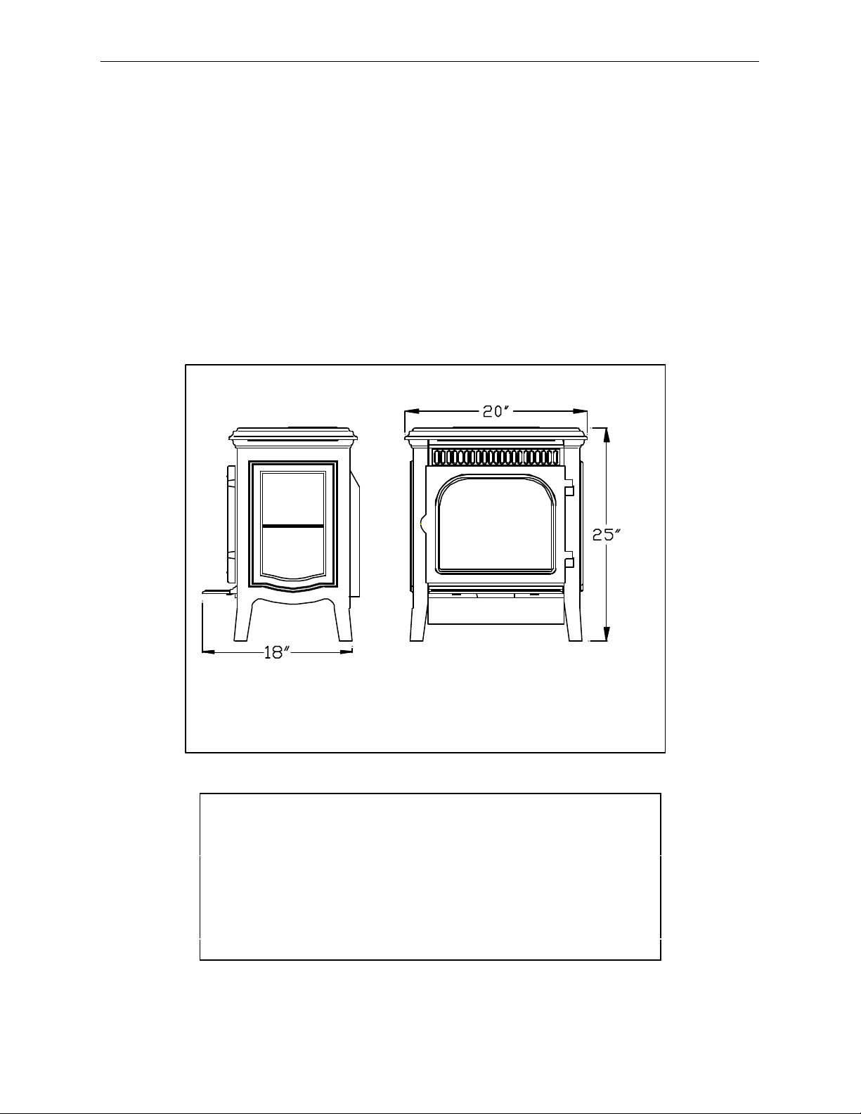
SPECIFICATIONS:
LISTED: DIRECT-VENT GAS HEATER
Listed: Gas-Fired Direct-Vent Fireplace Heater
Model: Tucson Direct-Vent Gas Fireplace Heater
Testing Agency: Intertek Testing Services NA Inc. (ITS)
Tested to: ANSI Z21.88-1998, CSA 2.33-M98, CAN/CGA2.17
Certified for Canada
Approved for
Mobile Home Installation (see page 7)
Figure 1: Tucson Dimensions
Input rating (Btu/hr) 0-1370 m 26,000 26,000
Maximum output (Btu/hr) 0-1370 m 19,000 19,700
Minimum input rating (Btu/hr) 14,500 14,500
Orifice size DMS 0-1370 m 40 53
Man. pressure- HI setting (in.w.c./kPa) 3.5/0.87 10.0/2.48
Man. pressure- LO setting (in.w.c./kPa) 1.2/0.30 3.3/0.80
Inlet pressure-Lo (in.w.c./kPa) 5.0/1.24 11.0/2.88
NG LP
Page 10

HearthStone Quality Home Heating Products Inc Tucson Model #8700
10
OWNER’S INFORMATION
The installation must conform with local
codes or, in the absences of local codes, the
current National Fuel Gas Code, ANSI Z223.1
(NFPA 54) or CAN/CGA B149 Installation
Code. (Installer l’appareil selon les codes ou
règlements locaux, ou, en l’absence de tels
règlements, selon les Codes d’installation
CAN/CGA-B149.)Do not use this appliance
if any part has been under water.
Immediately call a qualified service
technician to inspect the heater and to
replace any part of the control system and
gas control that has been under water. (Ne
pas se servir de cet appareil s’il a été plongé
dans l’eau, complètement ou en partie.
Appeler un technicien qualifié pour inspector
l’appareil et remplacer toute partie du système
de contrôle et toute commande qui ont été
plongés dans l’lau.)
DAILY OPERATION
The Tucson gas-fired heater is easily
operated by the homeowner once installed
and adjusted by qualified service personnel.
The unit is controlled via the wall-mounted
thermostat during the heating season. Set the
thermostat to the desired room temperature
and the unit will cycle on and off as
required. By adjusting the variable output
control located on the gas control valve, the
rate of heat output can be varied to meet the
heating requirements of the season.
Choosing a low flame setting will result in
longer burn cycles at a reduced output, while
choosing a high flame setting will result in a
shorter, hotter burn cycle. Through trial and
error, the homeowner can select the
optimum flame size for their setting and
application.
During the summer non-heating season,
switch the wall thermostat to “OFF”, and
turn off the pilot. This will improve the
overall efficiency of the unit as the heat
from the pilot is wasted. When putting the
unit back into service, follow the lighting
instructions described on page 31.
When the unit is first lit, especially when
cool, it is normal to experience some
condensation on the inside of the window
glass. This condensation will burn off within
the first few minutes of operation. If
continuous condensation on the window
glass or dripping water from any part of the
unit or venting system (chimney) is noted,
immediately discontinue operation of the
unit and contact qualified service personnel.
ROUTINE MAINTENANCE
AND CARE
The Tucson requires minimal routine
maintenance and care. The unit should
always be cool and off when being cleaned.
CLEANING
› WARNING: Do not clean the unit
when hot. The unit should receive
regular cleaning on, under, and around
the stove to prevent the buildup of dust
and lint. The exterior surfaces of the unit
can be cleaned using soap, water, and a
soft cloth. Do not use abrasive or
chemical cleaners and take care not to
scratch the glass or enamel finish (if so
equipped) when cleaning the unit. The
use of chemical wax based cleaners or
polishes are not recommended due to the
potential for discoloration or the enamel
when the residue of the cleaners or
polishes is exposed to heat.
Page 11
HearthStone Quality Home Heating Products Inc Tucson Model #8700
11
F IREBOX, PILOT, & BURNER
TUBES
The firebox should receive periodic cleaning
to prevent the accumulation of dust, lint, and
other debris. To clean the firebox, set the
thermostat to the “OFF” position, and turn
off the gas at the gas control valve. When
the unit is cool, unfasten the front door and
carefully remove the decorative ceramic
fiber log set, taking care not to damage the
logs or chip the enamel cast iron. Clean the
firebox burner tube and carefully vacuum
the entire surface of the log set. Thoroughly
vacuum the ports (holes) along the top of the
burner tubes.
With the decorative ceramic fiber logs out of
the firebox, fasten the door shut and
momentarily light the unit according to the
lighting instructions described on page 31.
Check to insure a flame is burning from
each burner port. The pilot flame should be
large enough to engulf the
sensor/thermocouple as shown in Figure 2.
Turn the unit off by setting the thermostat to
“OFF” and turning off the gas control valve.
Allow the unit to cool. Check and clean any
burner ports that are not burning or not
burning properly. Clean burner ports using
soft a soft brush or vacuum cleaner. If the
pilot flame height needs adjustment, it
should be adjusted by qualified service
personnel as described on page 34.
Figure 2: Pilot Flame Pattern
Complete the cleaning procedure by
carefully placing the log set within the
firebox as described on page 28. Close and
fasten the front door. Turn on the gas, light
the unit and check for proper operation.
Flame patterns should look like Figure 3.
Regularly check to insure the area around
the Tucson is kept free from combustible
materials, gasoline, and other flammable
vapors and liquids. Check that the flow of
com bustion and ventilation air is not
obstructed. Once a year the unit and venting
system should be inspected by qualified
service personnel to insure that they are
clean, free of obstruction, safe, and in good
working order. If service or maintenance is
required, it should be performed by qualified
service personnel.
Page 12
HearthStone Quality Home Heating Products Inc Tucson Model #8700
12
the gasket ends meet before trimming
any excess. Do not overlap the gasket
ends or leave ends with ragged edges.
7. Firmly and evenly press the gasket to
seat it in its channel.
CLASS CLEANING
If operating with propane, it may be
necessary to clean the inside of the glass
Figure 3: Burner Flame Pattern
REPLACE THE F RONT DOOR
GASKET AS NEEDED
Your Tucson uses a 3/8” rope-type
fiberglass gasket to make a tight seal
between the door frame and the firebox. In
time, the gasket can become brittle and
compressed and should be replaced. New
gasket material is available from your
Authorized HearthStone Dealer.
1. Allow the Tucson to cool completely.
Remove the existing gasket by grasping
one end and pulling firmly.
2. Use a wire brush or the tip of a
screwdriver to clean the channel of
remaining gasket.
3. Determine the correct length of the
appropriate-sized gasket by laying it out
in the channel. Allow an extra 1 to 2”
(25-50mm), and mark the spot to be cut.
4. Cut the gasket at the marked spot with a
utility knife. Twist the ends slightly to
prevent the gasket from unraveling.
5. Apply water glass adhesive to the gasket
channel.
6. Starting at one end, press the gasket into
the channel. Insure a good joint where
occasionally. Do not use abrasive cleaners.
Do not clean the glass when hot. Allow
glass to cool and apply a window cleaning
fluid.
› WARNING: Do not operate this
appliance with the glass panel removed,
cracked, or broken. Do not subject the
door to abuse, such as striking or
slamming shut. Replacement of the glass
panel should be done by a licensed or
qualified service person.
Page 13

HearthStone Quality Home Heating Products Inc Tucson Model #8700
13
INSTALLER’S
INFORMATION
CODES
Adhere to all local codes or, in their
absence, the latest edition of THE
NATIONAL FUEL GAS CODE ANSI
Z223.1 (NFPA 54) or CAN/CGA B149
Installation Code that can be obtained from:
AMERICAN NATIONAL STANDARDS
INSTITUTE, INC.
1430 BROADWAY
NEW YORK, NY 10018
OR
NATIONAL FIRE PROTECTION
ASSOCIATION, INC.
BATTERY MARCH PARK
QUINCY, MA 02269
The appliance when installed, must be
electrically connected and grounded in
accordance with local codes or, in the
absence of local codes, with the current
NFPA 70-National Electrical Code or CSA
C22.1-Canadian Electric Code.
A manufactured home (mobile) OEM
installation must conform with the
Manufactured Home Construction and
Safety Standard, Title 24 CFR, Part 3280
(U.S.) or Standard for Manufactured Home
Installation, ANSI/NCBCS A225.1 or
Standard for Gas Equipped Recreational
Vehicles and mobile Housing, CSA
Z240.4.CAN/SCA Z240 MH (Canada).
(Installer l’appareil selon les codes ou
règlements locaux, ou, en l’absence de tels
règlements, selon les Codes d’installation
CAN/CGA-B149.)
ITEMS REQUIRED FOR
INSTALLATION
* External regulator (for propane/L.P.G.
only)
* Piping which complies with local codes
* Pipe sealant approved for use with
propane/L.P.G. (resistant to sulfur
compounds)
* Manual shutoff valve
* Sediment trap
* Tee joint
* Pipe wrench
* Phillips head screwdriver
* Other parts as required by local code
*Safety Glasses
*Gloves
PACKING LIST
1-Tucson Gas-Fired Heater
2-Decorative Ceramic Fiber Logs
2-Ember Screen
1-Charcoal Embers
1-Owner’s Manual
1-Thermostat
1-40’ Thermostat wire
1-L.P. Fuel Conversion Kit
1-Warranty Validation Form
1-Exhaust Restrictor Kit
Note: Vent kits are supplied separately.
Failure to use the venting components
suggested by HearthStone will void your
warranty.
Page 14

HearthStone Quality Home Heating Products Inc Tucson Model #8700
14
UNPACKING AND INSPECTION
UNPACK AND INSPECT FOR DAMAGE
The Tucson is packaged by the manufacturer
to withstand shipment without damage.
However, damage can occur during transit
so take care to inspect for damage when
unpacking and installing the unit. If any
damage or missing parts are detected,
immediately contact your dealer. Do not
install or put into service a damaged or
incomplete heater.
Caution: The two top stones and grill are
NOT cemented or otherwise permanently
fastened in place! Carefully remove and set
aside the two stones and the grill. Use the
protective wrapping material to temporarily
protect the stones from chipping and damage
while the unit is inspected and installed.
Inspect the Tucson for visible or concealed
damage. The unit should appear to be square
and true. The stones should be whole and
without cracks, chips, or breakage. The
sheet metal parts should be smooth and free
of bends and dents. The enameled cast iron
should be free of chips or cracks. If visible
or concealed damage is found or suspected,
contact your dealer for instructions.
With the top stones and grill removed and
set aside, undo the lag bolts that fasten the
unit to the pallet. Take care not to mar or
chip the enameled legs. Lift the stove off the
pallet and set it into place.
The decorative ceramic fiber logs supplied
with the Tucson are contained within the
firebox. Always use great care when
handling the decorative ceramic fire logs as
they are fragile and subject to damage and
breakage if handled roughly. Open the
firebox door using a 1/8” allen wrench
screwdri ver and inspect the logs for damage.
If a broken log is encountered, contact your
dealer for replacement logs. Otherwise, set
the logs aside until called for during the
installation.
HEARTH REQUIREMENT /FLOOR
PROTECTION
The Tucson may be placed on a non-
combustible surface or wood floor. For
placement of the Tucson on carpeting, vinyl
tile or other combustible materials, the
appliance shall be installed on a metal or
wood panel extending the full width and
depth of the appliance. Installations must
meet local codes.
Page 15

HearthStone Quality Home Heating Products Inc Tucson Model #8700
15
CLEARANCE TO COMBUSTIBLES
Due to high surface temperatures, the unit
should be located out of traffic and away
from furniture and draperies. Clothing and
other flammable material should not be
placed on or near the heater. When
positioning the unit always maintain
adequate clearances around air openings into
the combustion chamber and allow for
adequate ventilation. Minimum clearances
to combustibles must be maintained as
shown in the illustrations on page 14 +15.
Note: The rear clearance to combustibles
will be determined by either the unit’s or the
vent pipe’s minimum clearance, depending
on whether the installation calls for vertical
rise within the room or a rear exit, throughthe-wall vent pipe.
Be sure to consider the need for access to
the gas control valve access door on the
front of the unit as well as full access for
periodic cleaning and servicing. Also
consider the location of the Optional Blower
Fan.
NOTE: These clearances represent minimum
distances in all cases, which, through te sting in an
independent laboratory to ANSI and CSA
standards, will prevent fire or spontaneous
combustion. We do not control the combustible
materials exposed to heat by this product;
therefore, an assessment must be made by the
installer to prevent consequential damage of walls
and flooring.
Figure 4: Minimum Venting-Mantle Clearance To
Combustibles
Figure 5: Minimum Venting-Wall Clearance To
Combustibles
Page 16

HearthStone Quality Home Heating Products Inc Tucson Model #8700
16
Figure 7: Snorkel-Wall Clearance To
Combustibles
Figure 6: Snorkel-Mantle Clearance To
Combustibles
Page 17

HearthStone Quality Home Heating Products Inc Tucson Model #8700
17
Acceptable Direct-Vent TERMINATION Cap locations.
Figure 8
Page 18

HearthStone Quality Home Heating Products Inc Tucson Model #8700
18
VENTING INFORMATION
VENTING CONNECTION
1. The Tucson Direct-Ven t is approved for
installation only with the vent
connecting components listed on this
page. Use the following instructions
along with the pipe manufacturer’s
instructions to complete the installation.
2. Attach the inner starter collar and gasket
to the unit with the eight # 8-32 x 3/8"
Phillips Head self-tapping screws.
NOTE: If required to use the restriction
plate, please refer to Figure 9 for correct
locations of the additional gasket, restriction
plate, and inner adapter configuration.
Make sure the screw head on the restriction
plate faces into the firebox. This will allow
for future adjustments if needed.
3. Place the outer starter collar and gasket
onto the back of the stove. Secure the
outer adapter with the eight # 8-32 x
3/8" Phillips Head self-tapping screws
that are provided. Install the rest of the
vent system according to the
manufacturer’s instructions.
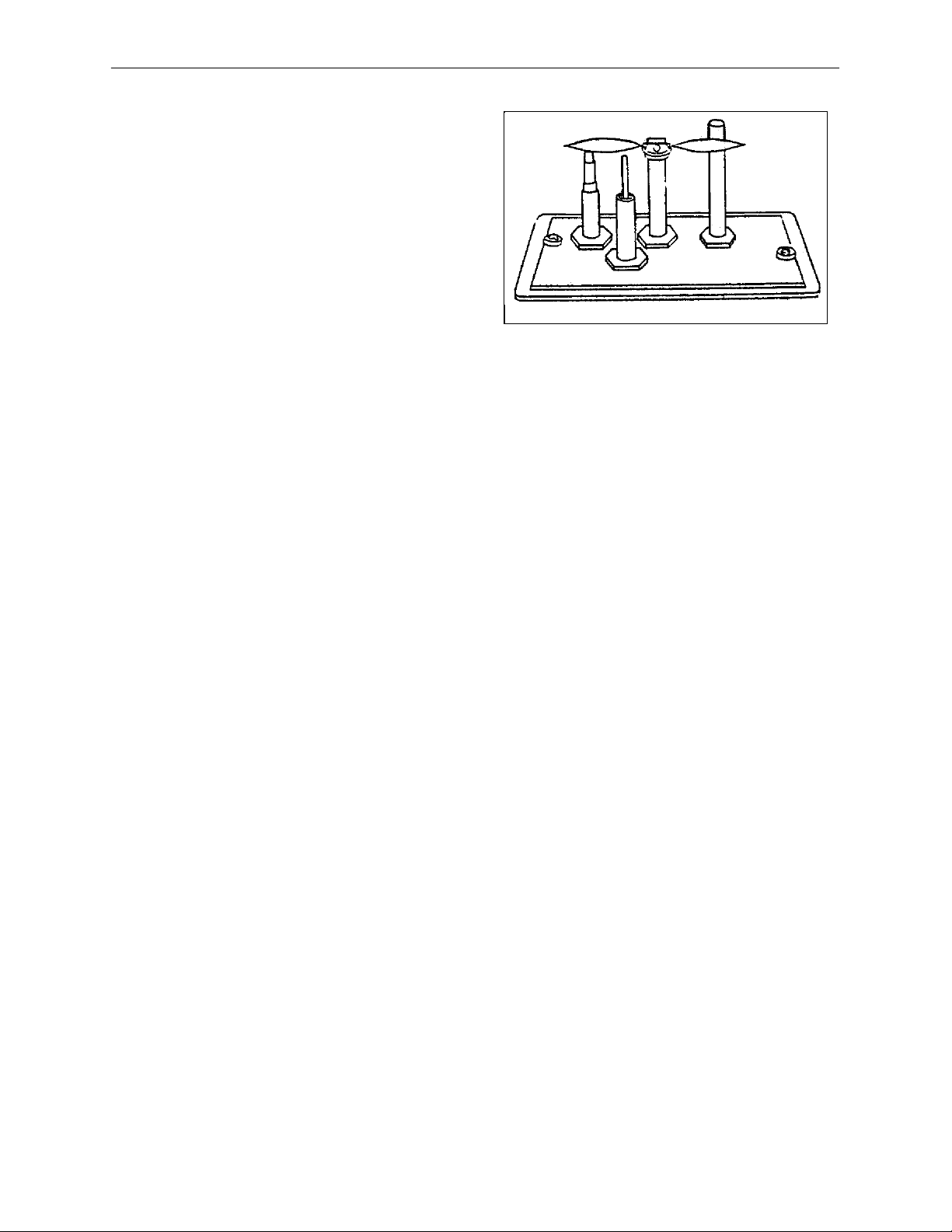
1. Restriction Plate 5950-922
2. Gasket 4” 3160-155
3. Inner starter 924H1
4. Gasket 6” 3160-157
5. Outer Starter 924H1
Figure 9: Gasket & Stove Adapter Installation
Page 19

HearthStone Quality Home Heating Products Inc Tucson Model #8700
19
RESTRICTION PLATE
The restriction plate is used to control the
draft of the heater. Controlling the draft also
changes the aesthetics of the flame. The
restriction plate has eight settings, one (1)
being the lowest and eight (8) being the
highest. For a fast moving flame with lots of
action, use a low setting. For a slow, lazy
flame, a high setting should be used. See
Figure 11 for instructions on how to adjust
the restriction plate settings.
RESTRICTION PLATE POSITION
A vent restriction plate is available for the
appliance to adjust the flow rate of exhaust
gases. This insures proper flames for the
wide variety of vent configurations and
efficiency. The restriction plate consists of a
rotating shutter below the starter section of
pipe and an adjustment plate with index
holes used to hold the shutter in a fixed
position. Depending on the vent
configuration, you may be required to adjust
the restriction plate position. Refer to pages
21 – 22 for positioning of the restriction
plate.
ADJUSTMENT TO RESTRICTION
(refer to Figure 11 for proper adjustment
plate index location) ‘A’ in Figure 11 shows
the locating screw that determines the
position of the plate.
NOTE: These positions are based on lab
results and can have some variance.
Remove the screw and position the
restriction plate in the desired location.
Fasten the screw into the proper hole and
tighten. Reinstall the exhaust baffle by
setting the back edge of the baffle into the
baffle clip attached to the back wall of the
firebox. Then push the baffle against the
heat exchanger and reinstall the fasten bolt.
Reinstall the log set and ember strip as
described in the log set installation
procedure on page 28.
PLATE
Remove the log set before adjusting
restriction plate by following the log set
removal on page 29. Make sure the unit is
cool before touching any part of the firebox
and log set. Remove the exhaust baffle by
removing the one screw in the center of the
baffle (refer to Figure 10). The baffle will
fall out once the screw is removed. Be
careful not to drop the baffle on the burner
tube or burner tube holder. Once the baffle
is set aside, check the restriction plate screw
location. There are eight locations that the
restriction plate can be positioned. (refer to
Venting Configuration – Figures 14 – 16 for
recommended restriction plate positions)
Figure 10: Baffle Removal
Figure 11 : Restriction Plate Adjustments
Page 20

HearthStone Quality Home Heating Products Inc Tucson Model #8700
20
VENTING COMPONENTS &
CONFIGURATION
The Tucson cannot be vented jointly with
any other solid fuel or gas appliance. It must
be vented directly to the outside of the
building using a proper termination as listed
in the manual. The only type of venting pipe
approved for use with your Tucson DirectVent stove is Simpson Dura-Vent’s GS,
AmeriVent Direct and Secure Vent DirectVent Pipe. The venting configurations are
shown in Figures 12 - 18. After determining
the venting configuration for your stove,
select the vent system that will
accommodate your installation.
Caution: Make sure all stove and
termination cap clearances have been
observed per the Owner’s Manual.
Caution: Be sure there is no wiring or
plumbing in the chosen location.
Caution: Venting terminals shall not be
recessed into a wall or siding.
Note: If further direction is needed for
installation, please refer to the venting
instructions, which are provided with the
venting components.
ACCEPTABLE DIRECT-VENT
TERMINATION CAP LOCATIONS
The vent/air intake termination clearances
above the high side of an angled roof are as
follows:
Roof Pitch Feet Meters
Flat to 6/12 1 0.3
7/12 to 9/12 2 0.6
10/12 to 12/12 4 1.2
13/12 to 16/12 6 1.8
17/12 to 21/12 8 2.4
Listed below are Simpson Dura-Vent,
AmeriVent Direct, and Secure Vent
components acceptable for installation,
along with the minimum venting kit
available. The venting system must be
comprised of the appropriate venting
components as specified.
APPROVED VENTING SYSTEM
COMPONENTS
*Component Description
90 0 Elbow
45 0 Elbow
6" Straight
9" Straight (Simpson only)
12" Straight
24" Straight
36" Straight
48" Straight
11" -14 5/8" Adjustable Pipe Length
Horizontal Vent Cap
Vertical Vent Cap
Snorkel 14
Vinyl Siding Standoff 4 x 6 5/8"
Round Ceiling Suppor t Wall
Thimble Covers
Wall thimble
CHIMNEY LINER SYSTEM
1. Direct-Vent Chimney Liner Termination
Kit
2. Chimney Liner Flex
3. Co-Linear Flex Connector
4. Co-Axial to Co-Linear Appliance
Connect
*MINIMUM VENT KIT
*HearthStone Stove Starter Collar
45º Elbow
90º Elbow
(2) 9” Straight
Round Ceiling Support
Wall Thimble Cover
Wall Thimble
Horizontal Vent Cap
*Supplied by HearthStone
Page 21

HearthStone Quality Home Heating Products Inc Tucson Model #8700
21
Top of Outlet
opening
14" snorkel
wall thimble
wall thimble cover
9"straight
45 degree elbow
Top of inner
stove exit
Figure 12: Components For a Typical Snorkel Installation
984
940
TOP OF
INNER PIPE
18"
TOP OF
INNER STOVE
EXIT
942
907B
945B
990B
907B
Figure 13: Components for a Typical Minimum Horizontal Venting Installation
Page 22

HearthStone Quality Home Heating Products Inc Tucson Model #8700
22
APPROVED VERTICAL
TERMINATION VENTING
CONFIGURATIONS WITH NO
ELBOWS OR (2) 45
F IGURE 14, AND (2) 90
0
OFFSETS,
0
ELBOWS,
F IGURE 15.
• 10' minimum system height (with or
without offsets)
• 35' maximum system height
• 6' maximum offset (refer to Figure 14)
• 11' maximum offset (refer to Figure 15)
The termination must fall within the
Outline shown in the Figures 14 & 15.
Use the indicated restriction plate
position. The Restriction Plate part # is
5950-922.
Figure 15: Vertical Termination Using (2) 90º
Elbows
Figure 14: Vertical Terminations Using Straight
Pipe
Clearances from the pipe to
combustibles:
1" to vertical runs
1" below and to the side of
horizontal runs
2" from the top of horizontal runs
Page 23

HearthStone Quality Home Heating Products Inc Tucson Model #8700
23
APPROVED VENTING CONFIGURATION FOR HORIZONTAL TERMINATION,
(1) 90
• The termination must fall within the area outlined by the shaded area shown in the
• A minimum of 9" rise is required directly off the heater.
• Use a vinyl siding Stand off when installing against vinyl siding.
• Horizontal sections require a 1/4" rise every 12" of horizontal run.
NOTE:
• The vent must terminate within one of the regions outlined by the shaded area.
• For each 90 0 elbow after 2, remove 5' from horizontal run.
• For Canadian installations: remove 4' from horizontal run.
• At minimum vertical rise, maximum horizontal run 14".
• Use with snorkel termination 14" maximum horizontal run.
0
ELBOW
illustration below.
Figure 22: Horizontal Termination Using (2) 90º Elbows
Page 24

HearthStone Quality Home Heating Products Inc Tucson Model #8700
24
APPROVED CONFIGURATION F OR FIREPLACE INSTALLATION
• The termination must fall within the demarcation line shown in illustration. Use the indicated
restriction plate position. Restriction plate # 5950-922.
Figure 17: Co-Linear & Chimney as Air Inlet
The use of an existing chimney as an air
intake is not covered under the ANSI
Z21.88-1998-CSA 2.33-M98 test methods
and the resulting ITS/WHI product
certification. The code Authority Having
Jurisdiction must be consulted prior to
proceeding with this installation method.
Figure 18: Co-Axial Installation
WARNING: Fai lure to use only parts
specifically approved with this appliance
may result in property damage or personal
injury.
Page 25

HearthStone Quality Home Heating Products Inc Tucson Model #8700
25
INSTALLATION INSTRUCTIONS
FOR THE STANDARD HORIZONTAL
TERMINATION MINIMUM
VENTING KIT (KIT #97-65001)
1. Install the 4” inner collar by first
placing the 4” x 6” gasket ring onto
the base of the collar. Install the
collar and gasket to the stove using 8
of the screws provided.
2. Install the outer collar in similar
fashion using the larger gasket ring
and the remaining 8 screws.
3. Install the 45º elbow over the outer
collar. Place the elbow so that the
twist lock end is pointing up.
4. Install one of the 9” pipe sections
into the elbow by fully inserting it
and turning approximately ¼ turn
clockwise, until the 2 sections are
fully locked. Install the 90º elbow in
similar fashion.
5. Move the stove and pipe assembly
back until the 90º elbow is flush to
the wall. The 9” vertical pipe should
be parallel to the wall. Draw a circle
around the pipe. Use the center of
this circle as the center point of the
10” x 10” square wall pass through.
(It should be approximately 40-1/4”
above the floor) Cut and frame the
wall pass through.
6. Place the interior wall thimble into
the 10” x 10” wall pass through.
Secure it with 4 screws (not
provided). Install the exterior portion
of the thimble in similar fashion,
overlapping the 2 sections.
› Caution: For building with vinyl siding,
a vinyl siding standoff should be
installed between the vent cap and the
exterior wall.
›
7. Install the horizontal vent
termination on the outside of the
wall. Make sure both of the retaining
straps extend through interior wall
thimble. Before attaching the vent
termination to the outside of the
house, run a bead of non-hardening
mastic around its’ outside edges, so
as to make a seal between it and the
wall. The arrow on the end cap
should point up. Secure the cap to
the wall with the appropriate screws.
8. Place the thimble cover onto the 90º
elbow. Put the 9” pipe into the
horizontal vent cap, (the vent pipe
must extend into the horizontal vent
cap a minimum of 1-1/4”). Move the
stove and vent pipe into position,
insert the 9” pipe into the 90º elbow
and twist to lock it. Secure the straps
from the horizontal vent termination
to the interior pipe with 2 sheet metal
screws, keeping screws close to wall
thimble as possible. Bend or cut the
excess strapping so that the thimble
cover will fit properly. Screw the
thimble cover to the wall.
Page 26

HearthStone Quality Home Heating Products Inc Tucson Model #8700
26
ELECTRICAL CONNECTIONS
NOTE: OPEN VALVE DOOR UNDER THE ASH LIP FOR ELECTRICAL AND GAS
CONNECTIONS.
THERMOSTAT
The ON/OFF/T’stat switch or wall mounted
thermostat controls the Tucson. We
recommend installation of the thermostat for
more comfortable performance, however
you may still override the thermostat by
setting the switch to “ON”. The thermostat
control s the unit by “calling for heat.” The
thermostat turns the unit on when the room
is cold, and turns the unit off once the room
is warmed sufficiently. The thermostat is
controlled by a 750 millivolt DC two-wire
circuit.
REMOTE CONTROL
There are two different optional remote
controls. Both of the remote controls are
capable of turning the unit on and off. One
of the optional remotes also allows you to
control the temperature of the stove, (in the
same way the thermostat controls the
heater), from anywhere in the vicinity of the
unit. If “ON” & “OFF” are the only controls
required, Kit #90-56912 can be used. If you
would like to control the temperature via the
remote control, use Kit #90-56914.
Installation instructions are provided with
the kits.
THERMOSTAT PLACEMENT
The thermostat should be placed in the same
room or living space as the unit. Typically
5’ (1.5m) off the floor and away from any
influences that may cause the temperature in
the vicinity of the thermostat to be
unrepresentative of the room temperature in
general. Such influences might include
strong lighting, a heater vent from the
central heating system, or a nearby drafty
window.
Placement of the thermostat on an inside
wall rather than an outside wall is
preferable. Do not place the thermostat
directly behind or too close to the unit,
otherwise heat from the unit will
immediately satisfy the thermostat and turn
the unit off.
THERMOSTAT WIRING
The thermostat should be connected to the
Tucson using no more than 40’ (12 m) of the
provided insulated thermostat wire. The
thermostat wire from the Tucson to the
thermostat can be surface mounted or routed
under the floor, through walls, etc.
Be sure to leave a small coil of thermostat
wire behind the Tucson so that the unit can
be moved out of position for servicing and
cleaning.
Connect one of the thermostat wires to the
gas control marked TH and the other to the
yellow wire coming from the on/off T’stat
switch . When making these connections,
position the thermostat wire so that it
extends towards the wall behind the Tucson,
then towards the thermostat.
At the thermostat, the wires should be
connected to the two connection screws on
the back of the thermostat per the
instructions received with the thermostat.
Take care not to over-tighten the connection
screws and not to damage the internal parts
of the thermostat.
Page 27

HearthStone Quality Home Heating Products Inc Tucson Model #8700
27
WIRING INSTRUCTIONS
› CAUTION: Label all wires prior to disconnection when servicing controls. Wiring errors
can cause improper and dangerous operation. Verify proper operation after servicing.
(Attention: Au moment de l’entretien des commandes, étiquetez tous les fils avant le
débranchement. Des erreurs de câblage peuvent entraîun fonctionnement inadequate et
dangereux.) The proper location of wire connections is shown in Figure 19.
Wiring Diagram - Tucson
Wiring Color KEY:
10 20 30 c
50 60 70 80 90
Hearthstone
50 70 90
c
10 20 30
OFF
O
O
Bk
G
R
YG
Y
Bk
W
B
Br
V
Bk
W
V
Y
W
W
G
Bk
BkBk
Bk
G G
W
Bk
BkBk
W
Figure 19: Wiring Diagram
Page 28

HearthStone Quality Home Heating Products Inc Tucson Model #8700
28
NOTE: If an optional blower is to be installed now or in the future, make sure the gas line is
installed as close to the floor as possible.
Figure 20: Gas Control Valve
GAS SUPPLY &
CONNECTIONS
› NOTICE: A qualified technician must
connect the heater to the gas supply
and leak test the unit before it is
approved for use. Consult all codes.
› WARNING: The unit must be installed
and connected in accordance with local
codes, or in the absence of local codes,
with the most current edition of the
National Fuel Gas Code ANSI Z223.1
(NFPA 54) or CAN/CGA B149
Installation Code.
GAS CONNECTIONS
The gas supply line connection is made to
the Tucson’s gas control valve just inside
the left front leg of the unit using a 3/8”
male NPT fitting. The supply line should be
½” diameter or appropriately sized to
provide a sufficient gas supply to meet the
maximum demand of the unit without undue
loss of pressure. We recommend a flexible
line to avoid undue mechanical load on the
valve and to ease thread alignment, but refer
to local codes.
› CAUTION: Check Gas Type!
GAS SUPPLY
This appliance and its individual shutoff
valve must be disconnected from the gas
supply piping system during any pressure
testing of that system at test pressures in
excess of ½ psig. The Tucson must be
isolated from the gas supply piping system
by closing its individual manual shutoff
valve during any pressure testing of the gas
supply piping system at test pressures equal
to or greater than ½ psig.
GAS PRESSURE ADJUSTMENT
NOTE: A QUALIFIED TECHNICIAN
MUST PERFORM THIS PROCEDURE!
Page 29

HearthStone Quality Home Heating Products Inc Tucson Model #8700
29
Once connected to the gas supply, the
supply line and manifold gas pressures must
be tested. The supply line pressure is tested,
to insure it meets the minimum gas supply
pressure as listed in the Specifications for
the type of fuel in use (natural gas or LP), by
connecting a manometer to the supply line
and adjusting the incoming pressure if
necessary to meet the required supply line
pressure as listed in specifications. The
manifold pressure tap on the gas control
valve, refer to Figure 20 for location.
LOG PLACEMENT
CAUTION: Fragile! Handle log set with
care. Always wear gloves and safety goggles
while handling the log set.
Only the decorative ceramic fiber log set
supplied with the unit should be placed in
the firebox. Do not place any other ceramic
logs, wood logs, or other materials in the
firebox. If the log set is damaged or broken
contact your dealer for replacement. The
decorative ceramic fiber log set will last a
long time, however, they will break if
subjected to rough or improper handling.
Exact positioning of the log set is required in
order to obtain a pleasing flame pattern and
efficient combustion. Incorrect log
placem ent may cause carbon build-up;
excess thermal stress on the log set and
stove parts, reduced efficiency, and high
levels of carbon monoxide. If the log set
does not set into the firebox exactly as
outlined, contact your dealer for assistance.
firebox by turning it
counterclockwise. Be careful not to
chip the enamel when loosening the
bolt. Pull the door open by grabbing
the top edge of the door frame.
2. Remove the packaging material
around the log set assembly. Be
careful not to damage the log set
when unpacking.
3. Gently place the Main Log (1) in the
firebox against the center of the back
wall.
4. Gently place the Top Log (2) on top
of the Main Log (1), inserting the
posts into the holes in the bottom
side of the Top Twig.
5. Spread evenly across the Ember
Screens, one layer high, the 2 ounces
of Charcoal Embers . You will not
need to use all of the Charcoal
Embers. Keep the rest to use in the
future.
6. With a 1/8” allen wrench, use the
bolt to fasten the door to the firebox.
Make sure the door and knob are
properly secured to the firebox
before turning the unit on. Be careful
not to chip the enamel when
fastening the door.
Gas Supply
Inlet
INSTALLATION OF THE LOG SET
(Refer to figures 21 & 22 for log set
assembly)
1. Open the front door using a 1/8”
allen wrench. Loosen the bolt that
fastens the doorknob to the door. It
also unfastens the door from the
Sediment Trap
To Equipment
Inlet
Tee Fitting
3" MIN.
Nipple
Cap
Page 30

HearthStone Quality Home Heating Products Inc Tucson Model #8700
30
Figure 21 Log Set
REMOVAL OF LOG SET
CAUTION: The log set and charcoal embers
retain heat and can be very hot! Allow 2 to
3 hours after pilot light is turned off before
handling.
To remove the log set, follow the
Installation of Log Set instructions in the
reverse order.
Figure 22: Log Set Assembly.
Page 31

HearthStone Quality Home Heating Products Inc TUCSON Gas-Fired Direct-Vent
31
LIGHTING THE UNIT FOR
THE FIRST TIME
› WARNING: If you do not follow these
instructions exactly, a fire or explosion
may result causing property damage,
personal injury or loss of life.
› CAUTION: Lighting the Tucson for the
first time and adjustments to the unit
should be performed by qualified service
personnel.
SMOKE AND F UMES WARNING
When lit for the first time, the Tucson will
emit some smoke and fumes. This is normal
“off-gassing” of the paints and oils used in
the manufacturing and assembly of the unit.
Open windows to vent the room if
necessary. The off gassing and fumes will
subside after the first 10 to 20 minutes of
operation.
BREAK-IN WARNING
The natural stones used in the assembly of
the Tucson were polished using a waterbased polishing system prior to the assembly
of the unit. Any residue moisture in the
stones must be dried out slowly to avoid
damaging the stones. This is accomplished
by adhering to the following break-in
procedure.
BREAK-IN PROCEDURE
When lit the first time, the Tucson should be
burned for no more than 15 minutes, then
allowed to cool for 1 to 2 hours. This gentle
warming and cooling of the unit will allow
any residual moisture in the stones to
evaporate slowly. Once this break-in
procedure has been completed, the Tucson
can be burned at will with no time
restrictions on the length of burn.
ODORS AND IMPURITIES
A heater of this type may produce odors
during heater operation due to impurities
that may exist in the immediate area.
Sources of impurities can be cleaning
solvents, paint solvents, cigarettes, smoke,
pet hair, dust, adhesives, new carpet, and/or
textiles. Such odors will dissipate. However,
opening a window or otherwise providing
additional ventilation to the area can
alleviate the condition. If any odor persists,
contact your dealer or an authorized service
technician.
Page 32

HearthStone Quality Home Heating Products Inc TUCSON Gas-Fired Direct-Vent
32
PILOT LIGHT WARNING
The Tucson has a piezoelectric spark igniter
(the push button located next to the gas
control valve behind the valve access door),
which ignites the pilot light by means of a
spark at the pilot light assembly. Do not
attempt to light the unit with a match or by
any means than the piezoelectric spark.
PREPARE F OR LIGHTING
Prepare for the lighting procedure by
adjusting the thermostat (if equipped) to its
lowest setting or OFF position. If the gas
control knob is not in the OFF position, turn
the knob fully clockwise to OFF. Locate the
variable output control knob and turn it fully
clockwise to the highest setting.
Prior to lighting the unit for the first time,
wait 5 minutes to allow any residual gas
within the unit to dissipate. Smell all around
the appliance area for gas. Be sure to smell
next to the floor because some gases are
heavier than air and will settle on the floor.
If you do not smell gas after this five-minute
period, proceed with the lighting procedure.
If you do smell gas, DO NOT proceed with
the lighting procedure. Instead, immediately
refer to the What To Do If You Smell Gas
Warning, on the cover of this manual.
WARNING: The valve control has an
interlock device. After shutting off all gas
flow, the pilot burner cannot be relit until
the thermocouple has cooled, allowing the
electromagnet to be released (approx. 60
seconds). The gas control knob is designed
to be operated by hand. Do not use any tools
during this operation. Damaged knobs may
result in serious injury.
INITIAL ADJUSTMENTS
Once the Tucson has been set in place,
connected and assembled as described in the
Clearances To Combustibles, Venting
Components & Configurations, Electrical
Connections, And Gas Supply and
Connections sections of this manual, the unit
is almost ready to be lit for the first time.
The manufacturer tests each unit prior to
shipment, so ignition should take place
without failure. However, a number of small
adjustments may be necessary to
compensate for variations in gas pressure,
altitude, and other factors particular to each
installation.
VARIABLE OUTPUT CONTROL
The gas control valve is equipped with a
variable output control. This control varies
the rate of heat produced by the unit by
varying the gas pressure to the main burner
tube. A combination of heat output and the
thermostat setting affect the length of the
burn cycle. If your stove turns on and off too
often, try, first, reducing the burn cycle by
turning the HI/LOW knob, on the control
valve, to a lower setting. Using the variable
output control, the heat output of the unit
can be reduced for mild fall and spring
months, or maximized for the colder winter
months. This adjustment can be made, by
the homeowner, as necessary by turning the
variable output control knob to “HI”, “LO”
or any setting in between.
AIR SHUTTER
The air shutter is used to regulate the air-togas combustion mixture, which in turn
influences the size and color of the flames.
The air shutter has been positioned in the
general location needed for the type of gas
being used, however, if the unit is not
burning as well as it should, then the air
shutter may need adjusting. The air shutter
may need adjustment once the unit has been
installed to compensate for variations in
supply line pressure, restriction plate
position, altitude, gas type conversions, and
other variables.
Page 33

HearthStone Quality Home Heating Products Inc TUCSON Gas-Fired Direct-Vent
33
To determine if the air shutter needs
adjustment, it is necessary to view the flame
pattern with the variable output control knob
at its highest setting. Allow the unit to
operate for 10 minutes to allow the entire
unit to reach temperature and for the flame
pattern to stabilize. Generally, the more air
(open shutter) in the mixture, the bluer the
flame. Less air (closed shutter) results in a
more yellow flame, but too little air will
result in incomplete combustion, low
efficiency and a dirty burn. There are two
simple guidelines to aid in determining the
correct flame pattern:
1. if the flame at the base of the logs is
completely blue, the air shutter may
be open too far;
2. if the flame is dirty or licks the top of
the stove, the air shutter may be
closed too far.
Some conditions cannot be corrected
through air shutter adjustment; an
adjustment must be made to the gas supply
pressure or by changing the restriction plate
location. Qualified service personnel must
perform supply line/manifold gas line
pressure adjustments and restrictor plate
adjustments Do not attempt to complete any
part of the installation or adjustment of this
unit unless technically qualified to do so.
LIGHTING INSTRUCTIONS
NOTE: The gas control knobs and the piezo
ignitor are located behind the control valve
access door, under the front of the unit.
1. STOP! Read the What To Do If You
Smell Gas! Warning (on the cover of
this manual).
2. Set the on/off/T’stat switch or thermostat
to the “OFF” position.
3. Unplug the fan accessory, if so
equipped.
4. Push in and turn gas control knob
clockwise to “OFF”. (If not previously
lit, the knob should be in this position.)
5. Wait (5) five minutes to clear out any
gas. If you then smell gas, STOP! Smell
all around the appliance area for gas.
Be sure to smell next to the floor because
some gases are heavier than air and will
settle on the floor. If you smell gas
immediately follow the What To Do If
You Smell Gas! warning on the cover of
this Manual. If you do not smell gas,
proceed to the next step.
6. Turn gas control knob counter-clockwise
to “PILOT”.
7. Push in control knob all the way and
hold in. Immediately light the pilot with
the gas lighter (push in and “click” the
piezoelectric spark ignitor button several
times until lit). Continue to hold the
control knob in for about 20 seconds
after the pilot is lit. Release the knob and
it will pop back out. Pilot should remain
lit. If the pilot goes out, repeat the
operation.
• If knob does not pop out when released,
stop, shut off the gas supply to the heater
and immediately call a qualified service
technician or gas supplier.
• If the pilot will not stay lit after several
tries, turn the gas control knob “OFF”
and call a qualified service technician or
gas supplier.
8. After the pilot lights, turn gas control
knob counter-clockwise to “ON”.
9. If the ON/OFF/T’stat switch is set to
“ON”, the stove should now be lit. If the
thermostat (or remote) has been
installed, set the ON/OFF/ T’stat switch
to “T’stat” and turn the thermostat (or
remote) to “ON”. Then set the desired
temperature.
Page 34

HearthStone Quality Home Heating Products Inc TUCSON Gas-Fired Direct-Vent
34
10. Shut the gas control valve access door.
11. Plug in the fan accessory, if so equipped.
12. If T’stat was selected, set thermostat to
“ON” and set desired temperature
setting. Normally, if T’stat position was
selected, the main burner is cycled on
and off by the thermostat or the “on/off”
switch located on the bottom of the
thermostat body.
NOTE: When pressing/clicking the
piezoelectric spark ignition button to light
the pilot, watch through the glass (front) of
the unit. Click the ignitor button until a
flame is visible at the pilot. Once the pilot is
lit, continue to press on the gas control knob
for another 20 seconds, then release.
Ascertain that the pilot is still lit by looking
through the front door. If lit, then turn the
gas control knob fully counter-clockwise to
the “ON” position. If the pilot fails to light,
or if it went out due to a premature release
of the gas control knob while pressed in the
“PILOT” position, wait 60 seconds for the
Interlock to release. Then repeat the lighting
process as described in this section of the
manual.
Once the pilot has been lit, the gas control
knob has been turned to the “ON” position,
and the ON/OFF/T’stat switch has been
turned to “ON”, the main burners should
light immediately. If you would like to use
the thermostat and it has been installed,
switch the ON/OFF/T’stat switch to
thermostat. Turn the thermostat to "ON" and
set it to a higher position so that it "calls" for
heat in order to turn light the main burners
(i.e. turns the unit on). Note that the
thermostat controls the on/off cycling of the
main burners, but the pilot remains lit
regardless of the thermostat setting. The
only way to turn the pilot off is to turn the
gas control knob fully clockwise to the
“OFF” position.
TO TURN OFF GAS TO APPLIANCE
1. Set the thermostat to the “OFF”
position or turn the ON/OFF/TSTAT switch to the “OFF”
position.
2. If shutting the unit off for the
non -heating season, turn the gas
control knob fully clockwise to
the “OFF” position. Do not force
the knob to turn.
AIR SHUTTER ADJUSTMENTS
The air shutter is adjustable while the stove
is burning by loosening the adjusting nut
located under the rear right hand corner of
the stove. This nut is hot and should not be
touched. Use only metal tools for this
adjustment.
Moving the nut toward the front of the stove
increases the air and moving the nut toward
the back of the stove decreases the air.
Tighten the nut after making adjustment.
The air shutter is factory set and only a
qualified gas technician should make
adjustments.
Note: Very little movement is needed to
substantially change the burn and flame
patterns.
Some conditions cannot be corrected
through air shutter adjustment; an
adjustment must be made to the gas supply
pressure. Supply line/manifold gas line
pressure adjustments must be performed by
qualified service personnel. Do not attempt
to complete any part of the installation or
adjustment of this unit unless technically
qualified to do so.
Page 35

HearthStone Quality Home Heating Products Inc TUCSON Gas-Fired Direct-Vent
35
PILOT ADJUSTMENT
The pilot light is preset by the manufacturer
and should not need adjustment. The pilot
light flame should be large enough to engulf
the thermopile and thermocouple located
next to the pilot, but not so large as to create
excessive noise or consume excessive gas.
(Refer to figure 23) However, it can be
adjusted by means of the pilot light
adjustment screw located on the gas control
valve. Open the valve door to access the
pilot adjustment screw. Note that the pilot
flame must engulf the thermopile so that the
thermopile can generate sufficient
milli-voltage (325 to 500-mv) to power the
milli-volt gas control valve. The flame on
the pilot should look like Figure 23.
Controlling the Tucson by the wall-mounted
thermostat may become erratic, nonexistent,
or the unit may go out, if the pilot flame is
too small or misdirected away from the
thermopile.
BURNER F LAME APPEARANCE
Once the unit is lit, observe the flame
pattern and adjust as necessary. Also, a
periodic visual check of the burner flame
should be performed. The burner flames can
be adjusted by means of the air shutter. To
determine if the burner flame needs
adjustment, it is necessary to view the flame
pattern with the variable output control knob
at its highest setting (turn fully clockwise).
Allow the unit to operate for 10 minutes
enabling the entire unit to reach temperature
and for the flame pattern to stabilize. The
flame pattern should be similar to the one
shown in Figure 24. There are several
guidelines to aid in determining if the flame
pattern is correct:
1. The flame should not be dirty, smoky,
sooty, or lick the top of the stove.
2. The flame should not rise off of the
burner tube, called “lifting”.
3. Flames should not impinge heavily on
the log set. They should “fit” through the
pre-formed spaces designed in the log
set.
Figure 23 Pilot Flame Pattern
WARNING
The control has an interlock device. If the
stove has been lit, it will not relight
immediately. After shutting off all gas flow,
the pilot burner cannot be relit until the
thermocouple has cooled, allowing the
electromagnet to be released (Approx. 60
sec.). The gas control knob is designed to
be operated by hand. Do not use any tools
during this operation.
Figure 24: Burner Flame Appearance
Page 36

HearthStone Quality Home Heating Products Inc TUCSON Gas-Fired Direct-Vent
36
MAINTENANCE AND
CARE
The Tucson requires minimal routine
maintenance and care. The unit should
always be cool and off when being serviced.
› WARNING: Do not substitute
materials. For replacement parts, or for
information about parts or service,
contact your local HearthStone dealer.
CLEANING
› WARNING: DO NOT CLEAN THE
UNIT WHEN IT’S HOT!
The unit should receive regular cleaning on,
under, and around the stove to prevent the
buildup of dust and lint. The exterior
surfaces of the unit can be cleaned using
soap, water, and a soft cloth. Do not use
abrasive or chemical cleaners and take care
not to scratch the glass or enamel finish (if
so equipped) when cleaning the unit. The
use of chemical or wax based cleaners or
polishes is not recommended due to the
potential for discoloration when the residue
of the cleaners or polishes is exposed to
heat.
F IREBOX
The firebox should receive periodic cleaning
to prevent the accumulation of dust, lint, and
other debris. To clean the firebox, set the
thermostat to the “OFF” position and turn
off the gas at the gas control valve. When
the unit is cool, remove the front and
carefully remove the decorative ceramic
fiber log set (after it has cooled), taking care
not to damage the logs or chip the enamel
cast iron. Clean the firebox, burner tube, and
pilot assembly and carefully vacuum the
entire surface of the log set. Take care to
thoroughly vacuum the ports (holes) along
the top of the burner tubes and the pilot
assembly.
PILOT & BURNER F LAMES
With the decorative ceramic fiber logs out of
the firebox, fasten the front shut and
momentarily light the unit according to
lighting instructions described in the How
To Turn the Unit On & Off section of this
manual. Check to ensure a flame is burning
from each burner port. The pilot flame
should be large enough to engulf the
thermocouple and thermopile as shown in
Figure 23.
NOTE: Do not operate the unit for more
than 1-2 minutes without the log set in
place. Turn the unit off by setting the
thermostat to “OFF”, and turning the gas
control valve off. Allow the unit to cool.
Check and clean any burner ports that were
not burning properly or at all. Clean burner
ports using a soft brush or vacuum cleaner.
If the pilot flame height needs adjustment it
should be adjusted by a qualified service
technician as described in the Initial
Adjustments section of this manual.
Complete the cleaning procedure by
carefully placing the log set within the
firebox as described in the Log Set
Information section of this manual. Fasten
the front door. Turn on the gas, light the unit
and check for proper operation. Flame
patterns should look like Figure 24.
Regularly check to insure the area around
the Tucson is kept free and clear from
combustible materials, gasoline, and other
flammable vapors and liquids. Check that
the flow of combustion and ventilation air is
not obstructed.
Page 37

HearthStone Quality Home Heating Products Inc TUCSON Gas-Fired Direct-Vent
37
Once a year the unit and its venting
system should be inspected by a qualified
service technician to ensure that it is
clean, free of obstruction, safe, and in
good working order. If service or
maintenance is required, a qualified
service technician should perform it.
CLEANING THE GLASS
If operating on propane, it may be necessary
to clean the inside of the glass occasionally.
Do not use abrasive cleaners, steel wool, or
a razor blade. Scratching the glass will
weaken the integrity of the glass. Your
dealer will usually stock a gas fireplace
glass cleaner or a window cleaning fluid will
work adequately. Do not clean when hot!
› WARNING: Do not operate this
appliance with the glass panel removed,
cracked or broken. A licensed or
qualified service technician should do
replacement of the glass assembly.
Contact your authorized dealer for
replacement glass.
NOTE: If the vent-air system is
disassembled for any reason, re-install per
the instructions provided in the Venting
section of this manual.
Page 38

HearthStone Quality Home Heating Products Inc TUCSON Gas-Fired Direct-Vent
38
PARTS LISTS
Part # Description Part # Description
1741-350 3-5/16” x 10-5/16”(84 x 262) Stone 5950-922 Restriction Plate
1741-351 7-1/2” x 6-1/2” (190.5 x 165) Stone 5710-596 Back Shroud
2310-850 HT Exc. Base 7210-103 Push Button Piezo Igniter
2310-860 HT Exc. 7211-430 Piezo Ceramic and Wire
2710-220 Ash Lip 7211-232 Burner Tube
2710-480 Exhaust Baffle 7211-310 Gas Valve SIT
2710-511 Front Door 93-56200 NG Conversion Kit
5710-170 Door Hinge Bracket 93-56201 LP Conversion Kit
5710-180 Door Latch Bracket 7200-240 Burner Orifice (NG) #40
2710-560 Glass Ret. Frame 7200-253 Burner Orifice (LP) #53
2710-581 Front Grill 7211-370 Pilot Burner Assembly
2710-810 Top Grill 7211-390 3 Way Pilot Hood and Clip
2710-321 Side. Right 7211-131 .30 Pilot Orifice (LP)
2710-326 Side, Left 7211-163 .62 Pilot Orifice
2710-655 Handle, Door 7211-470 Thermocouple
3030-027 Glass 13-1/4: x 1/8” x 5mm 7210-090 Thermopile
3110-057 3/8” Low Density Door Rope 7211-009 Pilot Tube
3160-080 ¾” Tape (glass)(FT) 7211-560 Main Log
3160-150 Gasket Firebox/Air Heat Exchanger 7211-561 Top Log
3160-075 5/8” x ¼” Rope Gasket 7211-558 Charcoal Embers
3160-152 Pilot Gasket 97-57000 Blower Kit
3160-155 Gasket 4” 5300-118 Limiter
3160-157 Gasket 6” 7000-015 Thermostat Wire 40’
5320-075 Ember Screen, Left 7200-506 Thermostat
5320-077 Ember Screen, Right 7000-200 3-Way On/Off Switch
5710-121 Valve Bracket 2710-116 Bottom Cast
5710-128 Valve Door 7211-231 Shutter, Air Slider
5320-072 Burner Tube Holder
5710-598 Back Shroud Extension
5710-470 Stone Clips
5710-512 Firebox/Air Plenum
5710-594 Exhaust Baffle Clip
› WARNING:
Do not substitute Materials. For replacement parts, or for information about parts or service,
contact your authorized HearthStone retailer. For the name of the authorized retailer nearest to
you, call (802) 888-5235 or write:
HearthStone Quality Home Heating Products
317 Stafford Ave. Morrisville, Vermont 05661
E-Mail: cservice@hearthstonestoves.com
Page 39

HearthStone Quality Home Heating Products Inc TUCSON Gas-Fired Direct-Vent
39
2. Pilot will not stay
TROUBLESHOOTING
Symptom Possible Cause Corrective Action
1. Pilot will not
light.
lit after carefully
following lighting
instructions.
A. Insufficient gas pressure,
air in the pilot line, or dirty or
kinked gas line.
B. Pilot orifice plugged.
C. Defective or misaligned
electrode at pilot.
D. Defective ignitor.
E. After sitting for "off"
season (summer), pilot
assembly may be dirty.
A. Low or too high gas
pressure
B. Faulty connections.
C. Defective thermocouple.
D. Pilot dirty or plugged.
A. Using the piezo sparker, try to light the
pilot. If it will not light, check the inlet gas
pressure.
B. Clean or replace the pilot assembly.
C. If a match lights a pilot, check the
electrode gap and location. Should be a 1/8"
gap in the flame area.
D. Check for a good connection between
ignitor and electrode. Check wire insulation.
If properly connected and no spark, replace
ignitor.
E. Clean or replace the pilot assembly.
A. Check for proper inlet pressure for the gas
being used.
B. Measure voltage between valve body and
solder connection on the rear of the valve
(where the blue wire connects). It should be
no less than 7 mV.
C1. Ensure that the thermocouple connection
at the gas valve is tight.
C2. Check thermocouple output using millivolt meter. Disconnect from valve and read
voltage across wire ends. If the reading is
less than 15 mV, replace the pilot assembly.
C3. If burning NG, check pilot flame to see
that it is impinging on the top of the
thermocouple. Clean or replace pilot for
maximum flame impingement.
D. Clean or replace the pilot assembly.
Page 40

HearthStone Quality Home Heating Products Inc TUCSON Gas-Fired Direct-Vent
40
TROUBLESHOOTING
Symptom Possible Cause Corrective Action
3. Pilot burning, no
gas to main burner,
valve knob in the
"ON" position,
thermostat and/or
on/off/t'stat switch
in the "ON"
position.
A. Thermostat switch or
wires defective.
B. Thermopile may not be
generating sufficient voltage.
C. Plugged burner orifice.
A. Check thermostat/wiring for proper
connections. Place jumper wire across
terminals at thermostat. If burner comes on,
replace defective thermostat. If not OK, place
jumper across thermostat wires at gas valve.
If burner comes on, tighten connections, or
replace faulty wires.
B. Check thermopile output, using a milli-volt
meter. Take the readings across generator
terminals of the gas valve. (TPTH and TP).
Milli-volt reading should be greater than 325
mV. If not, replace the pilot assembly. If the
meter reading is OK, but the burner does not
come on, replace the gas valve.
C. Remove and check burner orifice, clean or
replace. Note: do not use any metal cleaning
device, as this may damage the orifice.
4. Pilot and burner
come on, but go
out after some
warm-up.
5. Frequent pilot
outrage problem.
6. Glass fogs A. A normal result of gas
7. Blue Flames
A. Inconsistent, or
insufficient flame on
thermopile.
B. Insufficient gas pressure.
A. Pilot flame may be too
low or blowing, (high),
causing the pilot safety to
drop out.
combustion.
A. A normal result during the
first 20 minutes.
A. Adjust pilot flame size and assure that the
flame is aimed directly at the thermopile.
B. Chec k line pressure to ensure that the
correct inlet pressure is present for the type
of gas being used. If propane pressure is
inconsistent, check for water condensation at
the regulator.
A. Clean and/or adjust the pilot flame for
maximum impingement on the thermopile
and thermocouple.
A. After the heater has warmed up, the glass
should clear.
A. Flames should begin to turn more
yellowish after 20 minutes of burning.
B. If the blue color stays; adjust the air
shutter for a proper burn.
Page 41

HearthStone Quality Home Heating Products Inc TUCSON Gas-Fired Direct-Vent
41
A. Excessive primary air.
off position.
flames.
TROUBLESHOOTING
Symptom Possible Cause Corrective Action
8. Floating flames,
lazy ill-defined,
quiet flames, which
roll around,
sometimes
completely off of
the port,
sometimes with
overly, yellow tips.
Possible sooting.
Usually
accompanied by
the odor of
aldehydes.
9. Burner
flashback. Air-gas
mixture ignites
inside the burner
near the orifice,
usually creating a
roaring noise like a
blowtorch. The
problem is an
imbalance of gas
flow velocity and
burning speed
pattern.
A. Potentially dangerous
incomplete combustion due
to incorrect air to fuel ratio
(lack of combustion air or
excessive fuel delivery I.e.
excessive gas pressure,
overrating of appliance).
B. Incorrect air
intake/exhaust flow system.
Causes may be:
B1. Blocked burner.
B2. Blocked primary air
B3. Blocked secondary air
inlets
B. Burner input underrated.
C. Valve leak if flashback
occurs with burner valve in
D. Improper gas pipe size.
A. Check the appliance input rate and reduce
if necessary. The air intake/exhaust flow
system may be too restrictive or blocked (the
rate at which the exhaust leaves [draft]
determines the rate at which the combustion
air is delivered). Poor draft results in
insufficient air delivery or a restricted
exhaust. Correct air intake/exhaust flow
system.
B1. Clear ports.
B2. Clear obstructions.
B3. Clear obstructions.
C. If gas pressures are correct and the
flames stay the same, adjust the air shutter
for a proper burn.
A. Adjust the air shutter for a proper burn.
B. Check input rate. Check input pressure
using a manometer. Confirm correct gas
pressure at house meter or tank (call gas
company). Confirm burner orifice size.
C. Replace valve. If above corrections do not
eliminate flashback, replace burner.
D. Correct plumbing.
10. Delayed
ignition (makes a
sudden "whoosh"
noise as the burner
lights). This is a
buildup of gas prior
to ignition. This is
more prevalent with
propane (LP) fuel.
A. Incorrect air-to-fuel ratio.
A1. Primary air incorrect.
A2. Burner ports plugged.
B. Improper log placement.
A1. Adjust the air shutter for a proper burn.
A2. Open ports to allow for proper travel of
B. Reposition logs to eliminate interference
with flame travel.
Page 42

HearthStone Quality Home Heating Products Inc TUCSON Gas-Fired Direct-Vent
42
HEARTHSTONE GAS-FIRED STOVE AND INSERT
LIMITED WARRANTIES
These warranties give you specific legal rights. You may also have other rights which vary from State to State.
HearthStone Quality Home Heating Products, Inc. (HearthStone) warrants to the original purchaser only (the
“Original Purchaser”) the new gas-fired stove/insert manufactured by HearthStone and purchased by the Original
Purchaser (referred to as the “Stove” for simplicity) against any of the occurrences listed in this document that
result from defects in material or workmanship. All obligations of HearthStone under this document commence
on the date the Original Purchaser purchases the Stove (the “Purchase Date”).
LIMITED LIFETIME WARRANTY
HearthStone warrants the following parts of the Stove against the following occurrences that result from defects
in material and workmanship:
• All cast iron parts, including the cast iron heat exchanger – against breakage, cracking or burn-through.
• All stones – against cracking or breakage due to thermal stress, excluding surface and hairline cracks and
scratches that do not affect the operation or safety of the Stove.
• Glass – against breakage due to thermal shock.
LIMITED FIVE-YEAR WARRANTY
HearthStone warrants the following parts of the Stove against the following occurrences that result from defects
in material and workmanship:
• Firebox and firebox baffle – against breakage, cracking or burn-through.
• Convective heat exchanger – against breakage, cracking or burn-through.
• Burners, air shutters and orifices – against breakage, cracking or burn-through.
• Ceramic logs and embers – against breakage, cracking or burn-through.
This warranty expires on the fifth (5th) anniversary of the Purchase Date.
LIMITED THREE-YEAR WARRANTY
HearthStone warrants the following parts of the Stove against the following occurrences that result from defects
in material and workmanship:
• Gas train, including gas valve, millivolt wiring, spill switch, pilot assembly, thermopile, thermocouple,
piezo igniter, and, if the Stove is a vent-free model, ODS system – against breakage or malfunction.
This warranty expires on the third (3rd) anniversary of the Purchase Date.
LIMITED ONE-YEAR WARRANTY
HearthStone warrants the following parts of the Stove against the following occurrences that result from defects
in material and workmanship:
• Enamel Finish – against peeling or fading, excluding chipping, mechanical abrasion, chemical abrasion or
crazing.
• Gaskets and sealants – against breakage or deterioration.
• Accessories and electrical components such as blowers, switches and thermo discs, excluding venting
components, hearth components, electrical components and other components or accessories used in
conjunction with the installation of the Stove not manufactured or supplied by HearthStone – against
breakage or malfunction.
This warranty expires on the first (1st) anniversary of the Purchase Date.
Page 43

HearthStone Quality Home Heating Products Inc TUCSON Gas-Fired Direct-Vent
43
EXCLUSIONS
The warranties contained in this document do not cover, nor is HearthStone responsible for:
1. Damage resulting from installation or operation of the Stove in a manner contrary to the owner’s manual.
2. Damage or non-performance resulting from faulty or incomplete setup, installation and start-up or
mishandling, abuse, or misuse of the Stove, including but not limited to over-firing.
3. Damage resulting from installation, modification, alteration, repair or service of the Stove by any party
other than HearthStone or an authorized HearthStone dealer (a “Dealer”).
4. Damage due to water or due to installation of the Stove in a damp or high condensation area.
5. Damage due to installation of the Stove in an atmosphere contaminated by damaging chemicals, including
but not limited to chlorine, fluorine or salts.
6. Scratches on glass, enameled surfaces or stones due to mechanical abrasion.
7. Standard wear and tear of the Stove resulting from normal usage over time.
8. Damage, operational-related problems, or inadequate performance caused by site, installation or
environmental conditions beyond HearthStone’s control, including but not limited to nearby trees,
rooftops, buildings, wind, hills, mountains, inadequa te or excessive venting, insufficient make up air, or
negative air pressure whether or not caused by mechanical systems such as furnaces, exhaust fans, clothes
dryers, etc.
9. A defect in any part of the Stove if the Original Purchaser fails to comply with HearthStone’s or
a Dealer’s request to ship the part or the Stove to HearthStone or a Dealer, as the case may be.
THE WARRANTIES CONTAINED IN THIS DOCUMENT ARE EXCLUSIVE AND ARE GIVEN BY
HEARTHSTONE AND ACCEPTED BY THE ORIGINAL PURCHASER IN LIEU OF ALL OTHER EXPRESS
WARRANTIES AND ANY OBLIGATIONS, LIABILITIES, RIGHTS, CLAIMS, OR REMEDIES IN CONTRACT
OR TORT, WHETHER OR NOT ARISING FROM HEARTHSTONE’S NEGLIGENCE, ACTUAL OR IMPUTED.
ALL IMPLIED WARRANTIES, INCLUDING THE WARRANTIES OF MERCHANTABILITY AND FITNESS
FOR A PARTICULAR PURPOSE, ARE GIVEN ONLY TO THE EXTENT REQUIRED BY FEDERAL OR
STATE LAW. EXCEPT AS OTHERWISE REQUIRED BY STATE LAW, UPON THE EXPIRATION OF THE
EXPRESS LIMITED WARRANTIES CONTAINED HEREIN, NO IMPLIED WARRANTIES, INCLUDING THE
IMPLIED WARRANTIES OF MERCHANTABILITY OR FITNESS FOR A PARTICULAR PURPOSE, SHALL
APPLY TO THE SUBJECT STOVE. SOME STATES DO NOT ALLOW LIMITATIONS ON HOW LONG
AN IMPLIED WARRANTY LASTS, SO THE ABOVE LIMITATION MAY NOT APPLY TO YOU.
THE WARRANTIES CONTAINED IN THIS DOCUMENT EXTEND ONLY TO THE ORIGINAL
PURCHASER OF THE STOVE WARRANTED HEREUNDER. THEY DO NOT EXTEND TO ANY
SUBSEQUENT OWNERS.
UNDER NO CIRCUMSTANCES SHALL HEARTHSTONE BE LIABLE TO THE ORIGINAL PURCHASER
OR ANY OTHER PERSON FOR ANY INCIDENTAL OR CONSEQUENTIAL DAMAGES, INCLUDING
BUT NOT LIMITED TO DAMAGE TO PROPERTY OR PERSONAL INJURIES, WHETHER ARISING OUT
OF BREACH OF WARRANTY, TORT, OR OTHERWISE, EVEN IF HEARTHSTONE HAS BEEN
APPRAISED OF THE POSSIBILITY OF SUCH DAMAGES. SOME STATES DO NOT ALLOW THE
EXCLUSION OR LIMITATION OF INCIDENTAL OR CONSEQUENTIAL DAMAGES, SO THE
ABOVE LIMITATION OR EXCLUSION MAY NOT APPLY TO YOU.
QUALIFYING FOR WARRANTY COVERAGE
To obtain performance of any obligation under this document, the Original Purchaser must, within the applicable
warranty time period, contact HearthStone, at the address listed in the Warranty Registration section below or at
(802) 888-5235, or a Dealer for instructions regarding the return of defective parts for repair, the return of the
Woodstove for repair, or a Dealer service call. The Original Purchaser should refer to the Dealer network search
Page 44

HearthStone Quality Home Heating Products Inc TUCSON Gas-Fired Direct-Vent
44
engine contained on HearthStone’s Web site (www.hearthstonestoves.com), or call HearthStone at (802) 8885235, to find a Dealer nearest the Original Purchaser’s location.
REMEDY
The remedy for any breach of the foregoing warranties will consist of repair or replacement, at HearthStone’s
option, of any covered defect in the Stove. When the Original Purchaser contacts HearthStone or a Dealer,
HearthStone or the Dealer, as the case may be, will instruct the Original Purchaser to either return the defective
part, or the entire Stove (if needed), with shipping prepaid, to HearthStone or a Dealer or allow a Dealer to make
a service call at the place where the Stove is located. In the event the Original Purchaser refuses to allow a Dealer
to make a service call, HearthStone or a Dealer, as the case may be, will request that the Original Owner return
the defective part, or the entire Stove (if needed), with shipping pr epaid, to HearthStone or a Dealer.
Notwithstanding any other provision of this document, the Original Purchaser shall pay for any travel fees
and service charges related to a Dealer’s service call.
Parts: HearthStone will replace defective parts covered by the foregoing warranties at no charge.
Labor: Within the first (1st) year after the Purchase Date, HearthStone will pay for warranty labor performed by
a Dealer at HearthStone’s published labor rates in effect at the time the labor is performed. Thereafter, the
Original Purchaser is responsible for the cost of labor.
Shipping cost for parts: Within the first ninety (90) days after the Purchase Date, HearthStone will pay for the
shipping of Stove parts covered by any of the foregoing warranties to and from HearthStone or a Dealer, as the
case may be. Thereafter, the Original Purchaser is responsible for all shipping costs related to shipping Stove
parts to and from HearthStone or a Dealer, as the case may be.
Shipping cost for the Stove: Within the first (1st) year after the Purchase Date, if the Original Purchaser is
instructed to return the Stove to HearthStone or a Dealer for repair, HearthStone will pay fifty percent (50%) and
the Original Purchaser will pay fifty percent (50%) of the shipping costs related to shipping the Stove to and from
HearthStone or a Dealer, as the case may be. Thereafter, the Original Purchaser is responsible for one hundred
percent (100%) of all of the shipping costs related to shipping the Stove to and from HearthStone or a Dealer, as
the case may be. Notwithstanding any other provision of this document, in no event will HearthStone pay for any
Dealer fees or other fees for pick up or delivery of the Stove returned for repair; the Original Purchaser shall be
responsibl e for any such fees.
WARRANTY REGISTRATION
The Original Purchaser may send a completed and signed Warranty Registration Form, which is enclosed in the
Stove warranty packet, to the following address:
HearthStone Quality Home Heating Products, Inc.
Warranty Department
317 STAFFORD AVENUE
Morrisville, VT 05661
NOTE: SENDING IN THE SIGNED WARRANTY REGISTRATION FORM IS NOT A CONDITION OF
WARRANTY COVERAGE OR HEARTHSTONE’S PERFORMANCE.
 Loading...