

Hearth and Home Technologies TIARAI-CTO, TIARA II-B, TIARAI-CES, TIARAI-BR-B, TIARA I-B User Manual
...Page 1
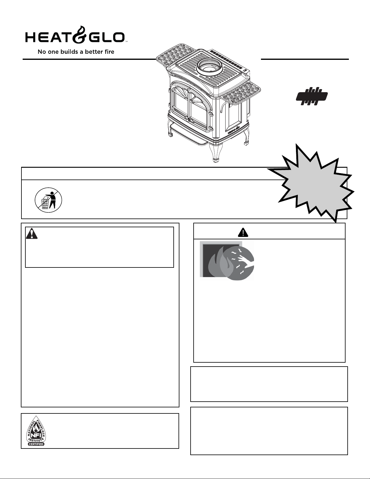
TIARA I-B
O-T L
Owner’s Manual
Installation and Operation
TIARA II-B
DIRECT VENT ROOM HEATER
Models:
TIARAI-BK-B
TIARAI-BR-B
TIARAI-CTO
TIARAI-CES
• Important operating and
maintenance instructions
included.
WARNING: If the information in these
instructions is not followed exactly, a fi re
or explosion may result causing property
damage, personal injury, or death.
• Do not store or use gasoline or other fl am-
mable vapors and liquids in the vicinity of this
or any other appliance.
• What to do if you smell gas
- Do not try to light any appliance.
Do not touch any electrical switch. Do not
use any phone in your building.
- Immediately call your gas supplier from a
neighbor’s phone. Follow the gas supplier’s
instructions.
- If you cannot reach your gas supplier, call
the fi re department.
• Installation and service must be performed
by a qualifi ed installer, service agency , or the
gas supplier.
TIARAII-BK-B
TIARAII-BR-B
TIARAII-CTO
TIARAII-CES
CAUTION
DO NOT DISCARD THIS MANUAL
• Read, understand and
follow these instructions
for safe installation and
operation.
Tested and
Listed by
O-T
C
OMNI-Test Laboratories, Inc.
Oregon USA
US
Portland
DO NOT
DISCARD
• Leave this manual with
party responsible for use
and operation.
WARNING
HOT SURFACES!
Glass and other surfaces are
hot during operation AND
cool down.
Hot glass will cause burns.
• Do not touch glass until it is cooled
• NEVER allow children to touch glass
• Keep children away
• CAREFULLY SUPERVISE children in the same room
as appliance
• Alert children and adults to hazards of high
temperatures
High temperatures may ignite clothing or other
fl ammable materials.
• Keep clothing, furniture, draperies and other
combustibles away.
In the Commonwealth of Massachusetts:
• installation must be performed by a licensed plumber or gas
fi tter.
See Table of Contents for additional Commonwealth of Massachusetts requirements.
Installation and service of this appliance should be
performed by qualifi ed personnel. Hearth & Home
T echnologies suggests NFI certifi ed or factory-trained
professionals, or technicians supervised by an NFI
certifi ed professional.
7010-149M
This appliance may be installed as an OEM installation in manufactured
home (USA only) or mobile home and must be installed in accordance with
the manufacturer's instructions and the manufactured home construction and
safety standard, Title 24 CFR, Part 3280 or Standard for Installation in Mobile
Homes, CAN/CSA Z240MH.
This appliance is only for use with the type(s) of gas indicated on the rating plate.
August 1, 2008
Page 2
Read this manual before installing or operating this appliance.
SAMPLE
O-T L
Please retain this owner's manual for future reference.
Congratulations
Congratulations on selecting a Heat & Glo gas appliance an elegant and clean alternative to wood burning appliances.
The Heat & Glo gas appliance you have selected is designed
to provide the utmost in safety, reliability, and efficiency.
As the owner of a new appliance, you'll want to read and
carefully follow all of the instructions contained in this
Owner's Manual. Pay special attention to all Cautions and
Warnings.
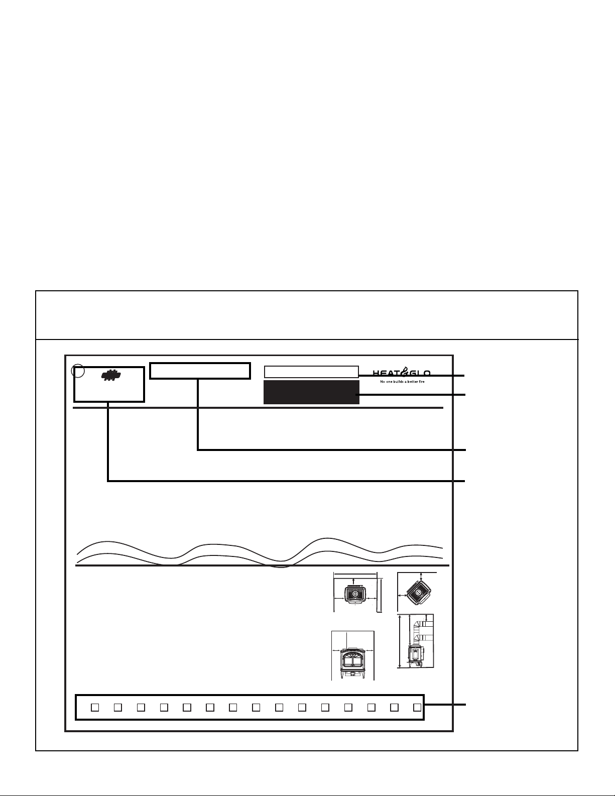
SAMPLE OF RATINGS LABEL
LOCATION: Hang tag attached to rear of appliance
Tested and
Report No. / Rapport Numéro
APPROVED FOR CANADA AND USA TO: ANSI Z21.88-2002 / CSA 2.33-02 Vented Gas Fireplace Heaters, and applicable sections of UL307b Gas Burning Heating Appliances for Manufactured Homes and Recreational
Vehicles, CAN/CGA 2.17-M91 Gas Fired Appliances for use at High Altitudes. This appliance is manufactured for operation with Natural Gas. For conversion to propane Manufacturer's instructions must be used. This
appliance may be installed in a bedroom or bedsitting room; in Canada remote thermostat installation is required.
APPROUVÉ-POUR LE CANADA ET LES ÉTATS-UNIS: ANSI-Z21.88-2002 / CSA 2.33-02 Fournaises au Gaz avec Ventilation, et les sections applicable de UL 307b Appareils de Chauffage Au Gaz our les Maisons Mobiles et les
Vehicules Motoriss, CAN/CGA 2.17-M91 Gas Fired Appliances for use at High Altitudes. Cet appareil est manufactur pour l'operation avec le Gaz Naturel. Pour une conversion au gaz propane les pices du Manufacturier et ses
instructions doivent tre utilises. Cet appareil peut tre utilis dans une chambre
FAN TYPE VENTED CIRCULATOR / VENTILATEUR CIRCULATOIRE
Optional Blower Kit #GFK-160A
120Vac, 60Hz., 12 Amperes or less (ou moins)
Route power cord away from unit. /
power cord under or over stove. /
0-2000 FT’ 0-2000FT
Input Rate on “HI” (BTU/Hr) 31,000 30,000 Puissance Évaluée à “HI” (BTU/Hr)
Input Rate on “LO” (BTU/Hr) 22,000 23,000 Puissance Évaluée à “LO” (BTU/Hr)
Maximum Output (BTU/Hr)** 20,943 21,519 Puissance Maximum (BTU/Hr**
Main Burner Orifice .106 .063 Orifice du Brûleur Principal
Minimum Inlet Pressure
Maximum Inlet Pressure
M
anifold Pressure on
**Max Venting, Blower On **Ventilation Maximum, Ventilateur Allumé
Portland
O-T
Oregon USA
Listed by
US
C
OMNI-Test Laboratories, Inc.
061-S-43b-5
/
Le Souifleur Optionel Kit #GFK-160A
Éloignez le fil électrique de l'appareil.
Ne pas faire passer le fil électrique au dessus ou en dessous de l'appareil.
“HI” (Inches W.C.)
MODEL / MODÈLE: TIARA I (B)
VENTED GAS FIREPLACE HEATER
NOT FOR USE WITH SOLID FUEL
FOURNAISE AU GAZ AVEC VENTILATION
NE PAS UTILISER AVEC LE COMBUSTIBLE SOLIDE
à coucher ou salle de sjour, au Canada, l'installation d'un thermostat à distance est exige.
(Inches W.C.)
(Inches W.C.)
Do not route
For use with Natural Gas
Usage Au Gaz Naturel
4.5” 11” Pression Minimum de la Valve (pouces W.C.)
7.0” 14” Pression Maximum de la Valve (pouces W.C.)
3.5” 10” Pression du Collecteur d’ Échappement à “HI” (pouces W.C.)
For use with Propane
Usage Au Gaz Propane
Serial No / Numéro du
007
This Owner's Manual should be retained for future reference.
We suggest that you keep it with your other important
documents and product manuals.
The information contained in this Owner's Manual, unless
noted otherwise, applies to all models and gas control
systems.
Your new Heat & Glo gas appliance will give you years of
durable use and trouble-free enjoyment. Welcome to the
Heat & Glo family of gas appliance products!
Serial No.
A division of Hearth & Home Technologies Inc.
20802 Kensington Boulevard, Lakeville, MN 55044
Barcode
Model Name
Test Lab &
Report No.
Page 2
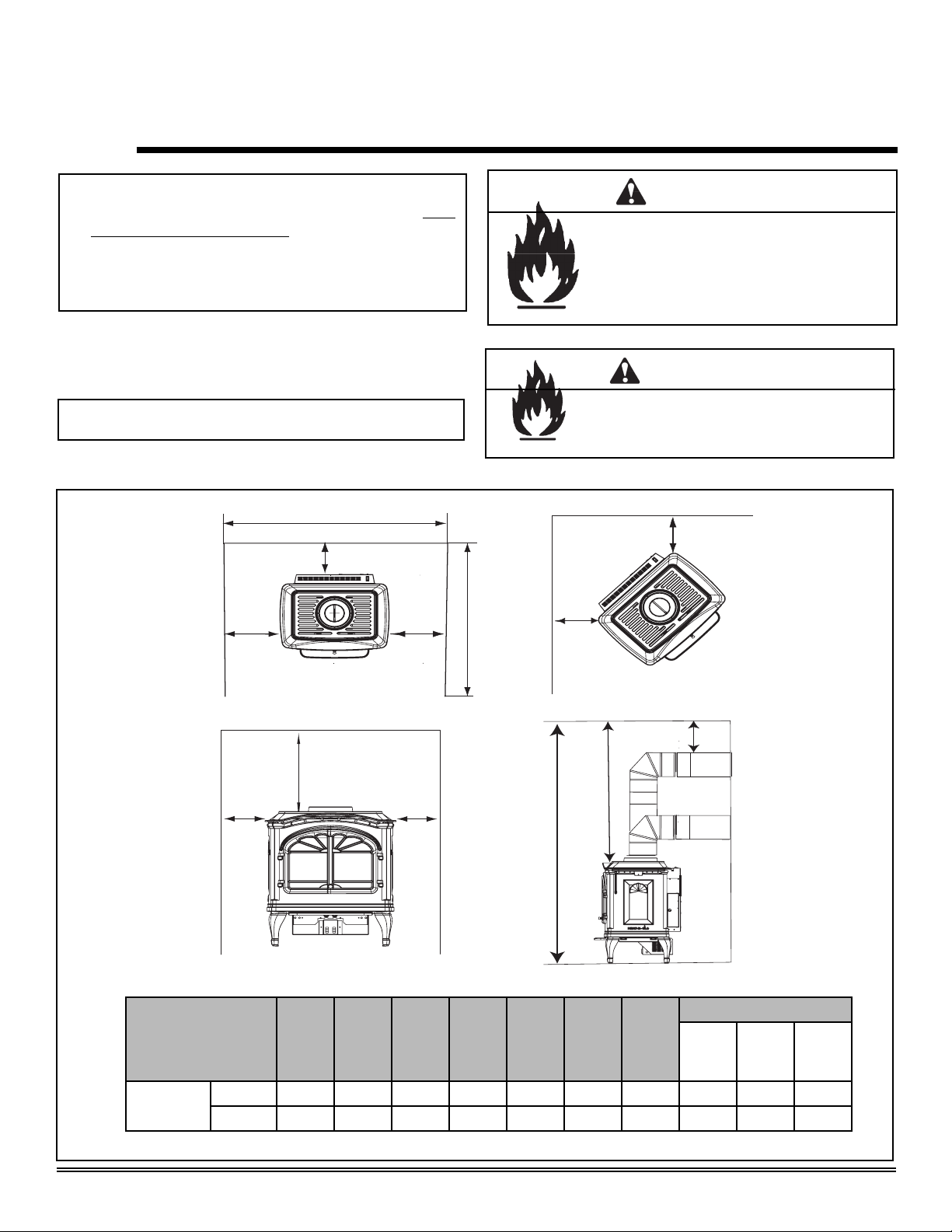
MINIMUM CLEARANCES TO COMBUSTIBLES / ESPACE MINIMUM AUX COMBUSTIBLES
Minimum clearances required from combustible construction for all appliance surfaces. / Espaces minimum exigés de la
A. Side of stove top to side wall 8-1/2" (216mm) D
B. Rear of stove to back wall 1/4" (6mm)
C. Corner of stove top to side wall 3/8" (9mm) Du coin du dessus du po
D. Minimum Alcove Height 54" (1372mm) Ha
E. Maximum Alcove Depth 36" (914mm) P
F. Minimum Alcove Width 40" (1016mm)
G. Stove to Ceiling Clearance 27" (686mm) Le po
H. Top of Pipe to Combustible 1-1/2" (38mm) Le sommet de tuyau à combustible
Side of Pipe to Combustible 1" (25mm) Le côté de tuyau à combustible
Inside Outside Cornerwall Vent 9" (229mm) À l'intérieur de conduit de mur de coin extérieur
HEARTH: A non-combustible hearth pad is not required. However, the floor beneath the stove must be stable, level, and strong
enough to support the stove without a tipping hazard. / CHEMINÉE: Un coussinet non-combustible de cheminée n’est pas
exigé. Cependant, le plancher en dessous du poêle doit être droit, à niveau et assez fort pour supporter le poêle sans le
hasard de basculer.
Right and left sides of appliance are determined when facing the front of appliance. / Les
l'appareil sont d
éterninés lorsque vous
2008 2009 2010 Feb Mar Apr May Jun Jul Aug Sep Oct Nov Dec Jan
DO NOT REMOVE THIS LABEL / NE PAS ENLEVER L’ÉTIQUETTE
construction combustible aux surfaces de l’appareil.
êtes en face de l'appareil.
u côté du poêle au côté du mur
Le contrôle arrière au mur arrière
uteur minimum du plancher au plafond
rofondeur maximum de l'alcove
Largeur minimum de l'alcove
SAMPLE
Date of Manufacture / Date du Manufacturier
êle au dégagement de plafond
êle au mur de côté
côté gauches et droits de
"A" measurement is from stove top,
not side /
sommet de poêle, pas le côté
A A
Made in U.S.A. / Fait Aux États-Unis
Heat & Glo · Tiara I B & Tiara II B · 7010-149M
F
B
A
"A"mesure est du
G -Alcove
de l'alcôve
A
E
C
G
D
90° off top up & out ceiling
clearance 90° du sommet en
haut et hors le degagement de
plafond
C
H
7010-150
Manufactured
Date
August 1, 2008
Page 3

- TABLE OF CONTENTS -
Section 1: Listing and Code Approvals
A. Appliance Certifi cations ......................4
B. Glass Specifi cations ............................4
C. Specifi cations ......................................4
D. High Altitude Installations ....................4
E. Non-Combustible Materials .................4
F. Combustible Materials ........................4
G. Requirements for the
Commonwealth of Massachusetts ......5
Section 2: Getting Started
A. Design & Installation
Considerations ....................................6
B. Tools and Supplies Needed................6
C. Inspect Appliance & Components .......6
Section 3: Appliance Location & Clearances
A. Selecting Appliance Location..............7
B. Clearances to Combustibles -
Tiara I-B ..............................................7
C. Clearances to Combustibles -
Tiara II-B .............................................8
Section 8: Appliance Setup
A. Remove Shipping Materials ................30
B. Top to Rear Conversion ......................30
C. Damper Adjustment ............................31
D. Shutter Adjustment .............................32
E. Leg Leveling System ...........................32
F. Installing the Baffl e - Tiara I-B .............32
G. Brick Installation - Tiara II-B ................32
H. Positioning the Logs - Tiara I-B ...........33
I. Positioning the Logs - Tiara II-B ..........34
J. Mineral Wool .......................................34
K. Embers ................................................34
L. Accessories .........................................34
M. Optional Blower ...................................35
N. Warming Shelves Installation ..............37
O. Glass Replacement .............................37
Section 9: Operating Instructions
A. Before Lighting Appliance ...................38
B. Controls ...............................................38
C. Lighting Appliance ...............................39
D. After Appliance is Lit ...........................40
E. Frequently Asked Questions ...............40
Section 4: Termination Locations
A. Vent Termination Minimum
Clearances..........................................9
Section 5: Vent Information
A. Venting Components ..........................11
B. Use of Elbows .....................................11
C. Measuring Standards ..........................11
D. How to Use the Vent Graph ................12
E. Venting Guidelines ..............................12
F. Horizontal Termination ........................13
G. Vertical Termination ............................16
Section 6: Gas Information
A. Fuel Conversions ................................24
B. Gas Pressures ....................................26
C. Gas Connection.. ................................26
Section 7: Electrical Information
A. Recommendation for Wire ..................28
B. Connecting to the Appliance ...............28
C. Standing Pilot Ignition System
Wiring ..................................................28
D. Ignition Module Access and
Battery Replacement ..........................29
Section 10: Troubleshooting ...............................41
Section 11: Maintaining & Servicing Appliance
A. Maintenance Tasks .............................44
Section 12: Reference Materials
A. Appliance Dimension Diagram -
Tiara I-B ..............................................45
B. Appliance Dimension Diagram -
Tiara II-B .............................................46
C. Vent Components Diagram ................47
D. Vent Components List ........................48
E. Service Parts List - Tiara I-B ...............50
F. Accessories - Tiara I-B .......................53
G. Service Parts List - Tiara II-B ..............54
H. Accessories - Tiara II-B ......................57
I. Warranty Policy ...................................58
J. Homeowner’s Notes ...........................59
K. Contact Information ............................60
August 1, 2008
Heat & Glo · Tiara I B & Tiara II B · 7010-149M
Page 3
Page 4
1
Listing and Code Approvals
A. Appliance Certifi cation
MODEL Tiara I B
LABORATORY OMNI-Test Laboratories, Inc.
061-S-43b-5
TYPE Vented Gas Fireplace Heater
STANDARD
MODEL Tiara II B
LABORATORY OMNI-Test Laboratories, Inc.
TYPE Vented Gas Fireplace Heater
STANDARD
The product is listed to ANSI standards for “Vented Gas
Appliance Heaters” and applicable sections of “Gas Burning
Heating Appliances for Manufactured Homes and Recreational Vehicles” and "Gas Fired Appliances for use at High
Altitudes".
Manufactured Home or Mobile Home installation may occur
only after the home is site located and must conform with
the Manufactured Home Construction and Safety Standard,
Title 24 CFR, Part 3280, or, when such a standard is
not applicable, the Standard for Manufactured Home
Installations, ANSI/NCSBCS A225.1, or Standard for Gas
Equipped Recreational Vehicles and Mobile Housing, CSA
Z240.4.
ANSI Z21.88-2002 ּ CSA 2.33-2002
UL307b ּ CAN/CBA 2.17-M91
061-S-44b-5
ANSI Z21.88-2002
ּ CSA 2.33-2002
UL307b ּ CAN/CBA 2.17-M91
C. Specifi cations
Model
(US or Canada)
Tiara I B
(NG)
Tiara I B
(LP)
Model
(US or Canada)
Tiara II B
(NG)
Tiara II B
(LP)
Maximum
Input
BTU
31,000 22,000 .106 81.43 57.33
30,000 23,000 .063 82.75 56.39
Maximum
Input
38,500 27,000 .120 81.36 60.97
39,000 30,500 .073 83.62 64.14
*Maximum Vent Blower On **Canada Only
BTU
Minimum
Input
BTU
Minimum
Input
BTU
Orifi ce
Size
Orifi ce
Size
*Steady
State
Effi ciency
%
*Steady
State
Effi ciency
%
**P.4
%
**P.4
%
D. High Altitude Installations
Omni-T est Laboratories, Inc. listed gas appliances are tested
and approved without requiring changes for elevations from 0
to 2000 feet in the U.S.A. and 0 to 4500 feet in Canada.
When installing this appliance at an elevation above 2000
feet, it may be necessary to decrease the input rating by
changing the existing burner orifi ce to a smaller size. Input
rate should be reduced by 4% for each 1000 feet above a
2000 foot elevation in the U.S.A. If the heating value of the
gas has been reduced, these rules do not apply. To identify
the proper orifi ce size, check with the local gas utility.
If installing this appliance at an elevation above 4500 feet (in
Canada), check with local authorities.
When installed, the appliance must be electrically grounded
in accordance with local codes or, in the absence of local
codes, with the National Electrical Code, ANSI/NFPA 70, or
the Canadian Electrical Code, CSA C22.1.
B. Glass Specifi cations
This appliance is equipped with 5mm ceramic glass behind
the curved glass. Replace glass only with 5mm ceramic
glass. Please contact your dealer for replacement glass.
NOTE: This installation must conform with local codes. In the
absence of local codes you must comply with the National
Fuel Gas Code, ANSI Z223.1-latest edition in the U.S.A.
and the CAN/CGA B149 Installation Codes in Canada.
Page 4
Heat & Glo · Tiara I B & Tiara II B · 7010-149M
WARNING
Do NOT use this appliance if any part has been under water.
Immediately call a qualifi ed service technician to inspect
the appliance and to replace any part of the control system
and any gas control which has been under water.
E. Non-Combustible Materials
Materials that are reported as passing ASTM E 136,
Standard Test Method for Behavior of Materials in a Vertical
T ube Furnace at 750°C, shall be considered non-combustible
materials.
F. Combustible Materials
Materials made of or surfaced with wood, compressed
paper, plant fibers, plastics, or other materials that can ignite
and burn, whether flame proofed or not, or whether plastered
or unplastered shall be considered combustible materials.
August 1, 2008
Page 5

NOTE: The following requirements reference various
Massachusetts and national codes not contained in this
document.
G. Requirements for the Commonwealth of
Massachusetts
For all side wall horizontally vented gas fueled equipment
installed in every dwelling, building or structure used in whole
or in part for residential purposes, including those owned or
operated by the Commonwealth and where the side wall
exhaust vent termination is less than seven (7) feet above
fi nished grade in the area of the venting, including but not
limited to decks and porches, the following requirements
shall be satisfi ed:
Installation of Carbon Monoxide Detectors
At the time of installation of the side wall horizontal vented
gas fueled equipment, the installing plumber or gas fi tter shall
observe that a hard wired carbon monoxide detector with an
alarm and battery back-up is installed on the fl oor level where
the gas equipment is to be installed. In addition, the installing
plumber or gas fi tter shall observe that a battery operated or
hard wired carbon monoxide detector with an alarm is installed
on each additional level of the dwelling, building or structure
served by the side wall horizontal vented gas fueled equipment. It shall be the responsibility of the property owner to
secure the services of qualifi ed licensed professionals for the
installation of hard wired carbon monoxide detectors.
In the event that the side wall horizontally vented gas fueled
equipment is installed in a crawl space or an attic, the hard
wired carbon monoxide detector with alarm and battery backup may be installed on the next adjacent fl oor level.
In the event that the requirements of this subdivision can not
be met at the time of completion of installation, the owner shall
have a period of thirty (30) days to comply with the above
requirements; provided, however, that during said thirty (30)
day period, a battery operated carbon monoxide detector with
an alarm shall be installed.
Approved Carbon Monoxide Detectors
Each carbon monoxide detector as required in accordance
with the above provisions shall comply with NFPA 720 and
be ANSI/UL 2034 listed and IAS certifi ed.
Signage
A metal or plastic identifi cation plate shall be permanently
mounted to the exterior of the building at a minimum height
of eight (8) feet above grade directly in line with the exhaust
vent terminal for the horizontally vented gas fueled heating
appliance or equipment. The sign shall read, in print size no
less than one-half (1/2) inch in size, “GAS VENT DIRECTLY
BELOW. KEEP CLEAR OF ALL OBSTRUCTIONS.”
Inspection
The state or local gas inspector of the side wall horizontally
vented gas fueled equipment shall not approve the installation unless, upon inspection, the inspector observes carbon
monoxide detectors and signage installed in accordance with
the provisions of 248 CMR 5.08(2)(a) 1 through 4.
Exemptions
The following equipment is exempt from 248 CMR 5.08(2)(a)
1 through 4:
The equipment listed in Chapter 10 entitled “Equipment
•
Not Required To Be Vented” in the most current edition of
NFPA 54 as adopted by the Board; and
Product Approved side wall horizontally vented gas fueled
•
equipment installed in a room or structure separated from
the dwelling, building or structure used in whole or in part
for residential purposes.
MANUFACTURER REQUIREMENTS
Gas Equipment Venting System Provided
When the manufacturer of Product Approved side wall
horizontally vented gas fueled equipment provides a venting system design or venting system components with the
equipment, the instructions provided by the manufacturer for
installation of the equipment and the venting system shall
include:
•
Detailed instructions for the installation of the venting system design or the venting system components; and
•
A complete parts list for the venting system design or
venting system.
Gas Equipment Venting System NOT Provided
When the manufacturer of a Product Approved side wall horizontally vented gas fueled equipment does not provide the
parts for venting the fl ue gases, but identifi es “special vent-
ing systems”, the following requirements shall be satisfi ed by
the manufacturer:
•
The referenced “special venting system” instructions shall
be included with the appliance or equipment installation
instructions; and
•
The “special venting system” shall be Product Approved
by the Board, and the instructions for that system shall
include a parts list and detailed installation instructions.
A copy of all installation instructions for all Product Approved
side wall horizontally vented gas fueled equipment, all venting instructions, all parts lists for venting instructions, and/or
all venting design instructions shall remain with the appliance or equipment at the completion of the installation.
See Gas Connection section for additional Commonwealth of Massachusetts requirements.
August 1, 2008
Heat & Glo · Tiara I B & Tiara II B · 7010-149M
Page 5
Page 6
2
Getting Started
A
. Design & Installation Considerations
Heat & Glo direct vent gas appliances are designed to operate with all combustion air drawn from outside of the building
and all exhaust gases expelled to the outside. No additional
air source is required.
CAUTION
Check building codes prior to installation.
• Installation MUST comply with local, regional, state
and national codes and regulations.
• Consult local building, fi re offi cials or authorities having
jurisdiction about restrictions, installation inspection,
and permits.
When planning an installation, it is necessary to determine
the following information before installing.
• Where the appliance is to be installed.
•
The vent system confi guration to be used.
• Gas supply piping.
• Electrical wiring.
• Whether optional accessories - devices such as a
blower, thermostat or remote control - are desired.
WARNING
Keep appliance dry.
• Mold or rust may cause odors.
• Water may damage controls.
B. Tools and Supplies Needed
Before beginning the installation be sure that the following
tools and building supplies are available. Note: Not all
tools will apply to every installation.
C. Inspect Appliance & Components
WARNING
Inspect appliance and components for
damage. Damaged parts may impair safe
operation.
• Do NOT install damaged components.
• Do NOT install incomplete components.
• Do NOT install substitute components.
Report damaged parts to dealer.
• Carefully remove the appliance and components from
the packaging.
• Remove door and set aside on protective surface.
• Remove log set and component pack from fi rebox.
• Report to your dealer any parts damaged in shipment,
particularly the condition of the glass.
• Read all of the instructions before starting the
installation. Follow these instructions carefully
during the installation to ensure safety and benefi t.
WARNING
Hearth & Home Technologies disclaims any
responsibility for, and the warranty will be
voided by, the following actions:
• Installation and use of any damaged appliance or vent
system component.
• Modifi cation of the appliance or vent system.
• Installation other than as instructed by Hearth & Home
Technologies.
• Improper positioning of the gas logs or the glass door.
• Installation and/or use of any component part not approved
by Hearth & Home Technologies.
Any such action may cause a fi re hazard.
Pliers Gloves
Hammer Framing Square
Phillips Screwdriver Electric Drill / Bits
Flat Blade Screwdriver Safety Glasses
Plumb Line Voltmeter
Level Wrenches
Manometer Allen Wrench Set
Tape Measure Ratchets / Sockets
1/2 - 3/4 in. Length, #6 or
#8 Self-Drilling Screws
Page 6
Non-corrosive Leak Check
Solution or Combustible Gas
Detector
Heat & Glo · Tiara I B & Tiara II B · 7010-149M
August 1, 2008
Page 7
3
Appliance Location and Clearances
NOTE:
· Illustrations refl ect typical installations and are FOR
DESIGN PURPOSES ONLY.
· Illustrations/diagrams are not drawn to scale.
· Actual installation may vary due to individual design
preference.
A. Selecting Appliance Location
When selecting a location for your appliance it is important to
consider the required clearances to wall (see Figure 3.1).
NOTE: For actual appliance dimensions refer to
Section 12.
B. Clearances to Combustibles - Tiara I-B
F
B
A
A
E
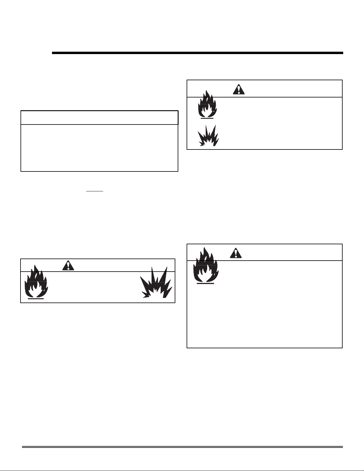
WARNING
Fire Risk
Provide adequate clearance:
• Around air openings
• To combustibles
• For service access
Locate appliance away from traffi c areas.
WARNING
Fire Risk.
• Locate and install appliance to all
clearance specifi cations in manual.
C
C
"A" measurement is from
appliance top, not side
G
A
A
D
90˚ off top up and out ceiling
Model A B C D E F G
Tiara I B
Inches
Millimeters
8-1/2 1/4 3/8 54 36 40 27 1-1/2 1 9
216 6 9.5 1372 914 1016 686 38 25 229
G
H
Top of
pipe
H
Side of
pipe
Inside
Outside
corner
wall vent
Figure 3.1
August 1, 2008
Heat & Glo · Tiara I B & Tiara II B · 7010-149M
Page 7
Page 8
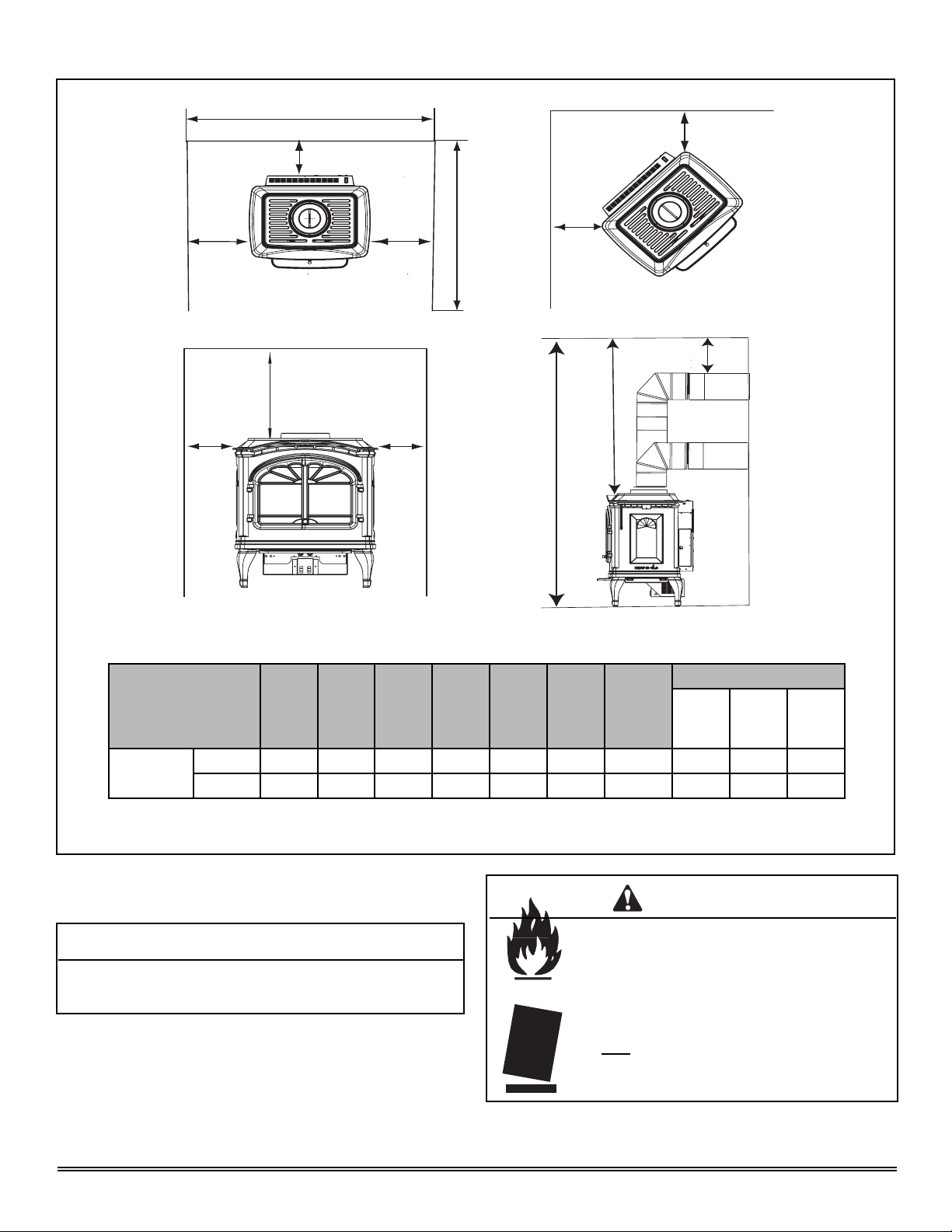
C. Clearances to Combustibles - Tiara II-B
F
B
C
A
"A" measurement is from
appliance top, not side
G
A
A
A
E
C
H
G
D
90˚ off top up and out ceiling
Model A B C D E F G
Tiara II B
Figure 3.1
For both the Tiara I-B and Tiara II-B, it is permissible to place
the appliance on carpet.
Inches
Millimeters
5-1/4 1/4 3/8 54 36 40 31-3/4 1-1/2 1 9
133 6 9.5 1372 914 1016 806 38 25 229
CAUTION
Some carpet materials may be sensitive to radiant heat from the
appliance causing discoloration or odor.
NOTE: Flooring beneath appliance may reach 90 degrees
plus room ambient temperature. Check with flooring
manufacturer for maximum temperature allowed on flooring
surfaces.
H
Top of
pipe
Side of
pipe
Inside
Outside
corner
wall vent
WARNING
Fire Risk.
Odor Risk.
Tipping Risk
• Install appliance on a stable, level platform/
fl oor strong enough to support appliance
without tipping.
• USE wood fl ooring, ceramic tile, brick hearth
or high pressure laminate fl ooring applied
directly over the sub-fl ooring material.
Page 8
Heat & Glo · Tiara I B & Tiara II B · 7010-149M
August 1, 2008
Page 9
Termination Locations
4
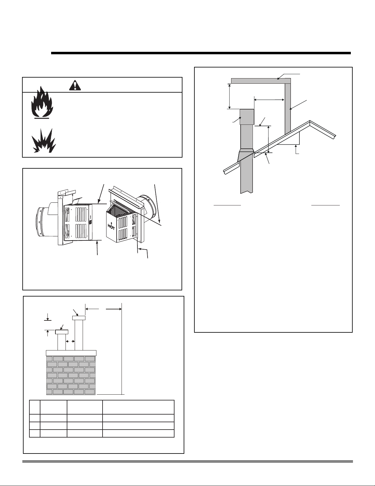
A. Vent Termination Minimum Clearances
WARNING
Fire Risk.
Explosion Risk.
Maintain vent clearance to combustibles
as specifi ed.
• Do not pack air space with insulation or
other materials.
Failure to keep insulation or other materials
away from vent pipe may cause fi re.
Measure vertical clearances from this surface.
Measure horizontal clearances from this surface.
(See Figure 4.4 for specifi c clearances.)
Figure 4.1 Termination Clearances
GAS, WOOD OR FUEL
OIL TERMINATION
B
HORIZONTAL
OVERHANG
2 FT.
MIN.
GAS DIRECT VENT
TERMINATION CAP
20 INCHES MIN.
LOWEST
DISCHARGE
OPENING
X
12
ROOF PITCH
IS X/ 12
H (MIN.) - MINIMUM HEIGHT FROM ROOF
TO LOWEST DISCHARGE OPENING
Roof Pitch H (Min.) Ft.
Flat to 6/12 .........................................................1.0*
Over 6/12 to 7/12........................................................1.25*
Over 7/12 to 8/12 ............................................... 1.5*
Over 8/12 to 9/12 ............................................... 2.0*
Over 9/12 to 10/12 ............................................. 2.5*
Over 10/12 to 11/12 ........................................... 3.25
Over 11/12 to 12/12 ........................................... 4.0
Over 12/12 to 14/12 ........................................... 5.0
Over 14/12 to 16/12 ........................................... 6.0
Over 16/12 to 18/12 ........................................... 7.0
Over 18/12 to 20/12 ........................................... 7.5
Over 20/12 to 21/12 ........................................... 8.0
* 3 foot minimum in snow regions
VERTICAL
WALL
GAS
TERMINATION
C
A
Gas
Termination
A 6 in. 20 in. min. Horizontal distance between terminations
B 20 in. 24 in. min. Distance to perpendicular wall
C 18 in. 18 in. Vertical distance between terminations
Figure 4.2 Multiple Vertical Temination
August 1, 2008
Wood & Fuel Oil
Termination
Comments
Heat & Glo · Tiara I B & Tiara II B · 7010-149M
Figure 4.3 Minimum Height from Roof to Lowest Discharge
Opening
Figure 4.3 specifi es minimum vent heights for various
pitched roofs.
Page 9
Page 10
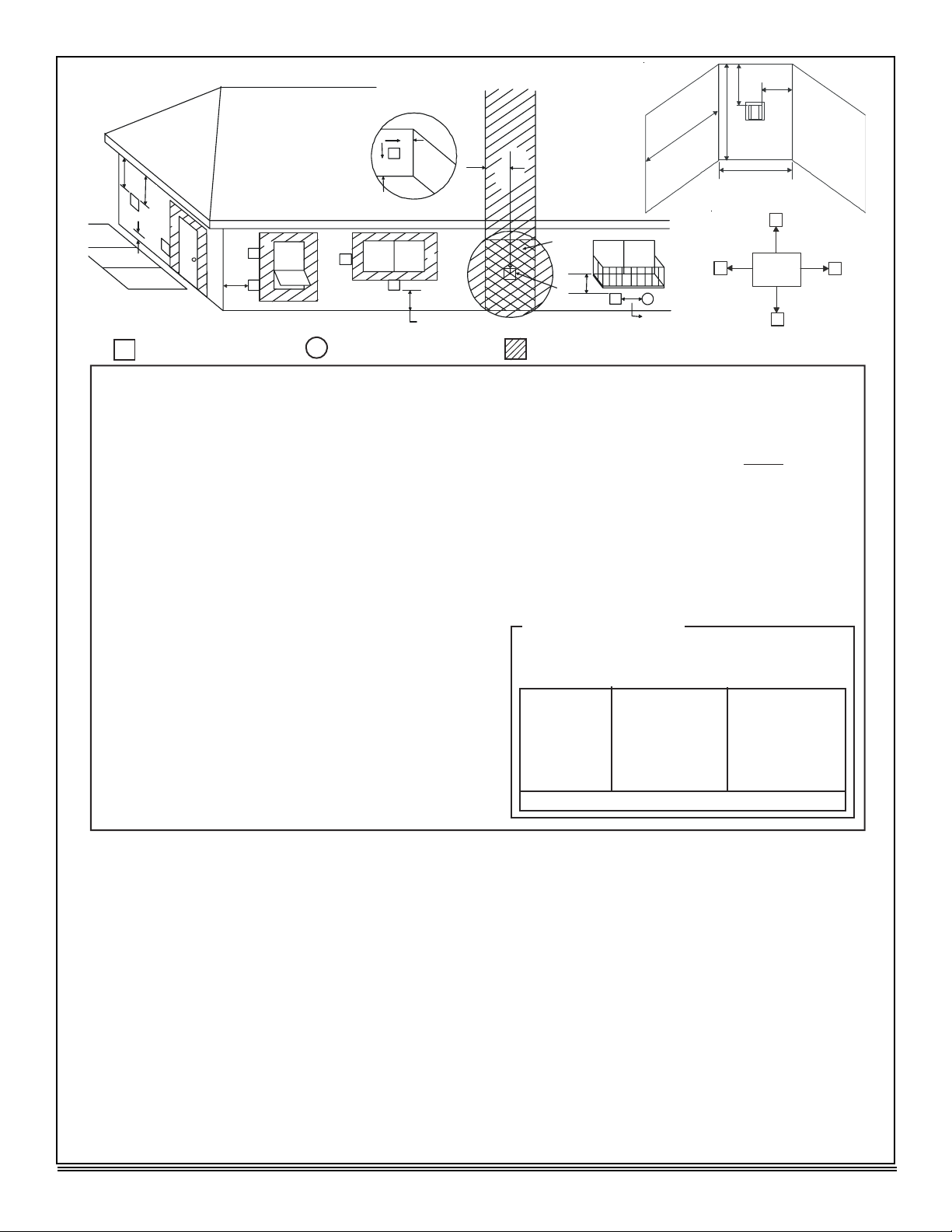
o
M
N
P
X
J or K
R
Q
(See Note 2)
S
Electrical
V
V
T
Service
D*
V
S
V
G
v
D
E
v
B
L
v
B
v
F
v
A
B
v
B
v
H
U.S.
(3 FT)
M
I
v
A
= VENT TERMINAL
V
A = 12 inche s ............. clearances above grade , veran-
(S ee N ot e 1 )
X
= AIR SUPP L Y INLET = ARE A WHERE TERMINA L IS NOT PERMITTED
da, porch, deck or balcon y
B = 12 inche s ............ clearances to window or doo r
that may be opened, or to per manen t ly closed windo w . ( G lass )
D * = 12 inche s ............. ver t ical clearance t o unven t ila t -
ed s o f f i t o r t o v en t ila t ed s o f f i t lo c a t ed above t he t ermina l
*30 inche s ............ f o r v in y l c lad s o ff i t s and belo w
electrical servic e
F = 9 inche s ............. . c l earance to outside corne r
G = 6 inche s ............... c lea r an c e t o in s ide c o r ne r
H = 3 f t. (Canada ) ..... . not to be ins t alled above a ga s
meter/regulator assembly within 3
feet (90cm) horizon t ally from th e
center-line of the regulato r
I=3ft.
................
....... clearance to gas service regula -
tor vent outle t
J = 9 inches (U.S.A. )
12 inches (Canada ) clearance to non-mechanical ai r
supply inle t t o building or t h e
combustion air inlet to any othe r
applianc e
K = 3 ft. (U.S.A. )
6 f t. (Canada ) ......... clearance to a mechanica l
(powered) a i r s uppl y inle t
L* * = 7 ft . ......................... c le arance a bove p ave d
(S ee N ot e 1 )
sidewalk or a paved drivewa y
located on publi c propert y
M** * = 18 inche s .............. clearance under veranda ,
porch, deck, balcony or over han g
42 inche s .............. viny l
S = 6 inche s ................. cle a r a n ce f rom s ides o f
(S ee N ot e 3 )
electrical servic e
T = 12 inche s ................ c lea r a n c e abo v e ele ctr i c a l
(S ee N ot e 3 )
servic e
Alcove Application s
N = 6 inche s ................. non-vinyl sidewall s
P = 8 ft .
_____________________________________________________________________
_____________________________________________________________________
_____________________________________________________________________
_____________________________________________________________________
12 inche s ............... v in y l sidewall s
Q
MI N
1 ca p 3 f ee t 2 x Q
2 ca p s 6 fee t 1 x Q
3 ca p s 9 fee t 2/3 x Q
4 ca p s 12 fee t 1/2 x Q
Q
= # termination caps X 3
MIN
R
= (2 / # termination caps) x Q
MAX
R
MA X
ACTUA L
ACTUA L
ACTUA L
ACTUA L
ACTUAL
* * a vent shall not terminate directly above a sidewalk or p ave d
driveway which is located between two single family dwellings an d
serves both dwellings.
** * onl y pe rm i tt ed i f v e r anda , po rc h , de ck o r bal c on y i s f ull y open o n
a minimum o f 2 sides benea t h t he f loo r , or mee t s No t e 2 .
NOTE 1: On private property where termination is less than 7 feet above
a sidewalk, drivewa y , deck, porch, veranda or balcon y , use of a listed
cap is suggested. (See vents components pages.)
NOTE 2: T ermination in an alcove space (spaces only open on one side
and withat an overhang) are permitted with the dimensions specified for
vinyl or non-vinyl siding and so f fits. 1. There must be at least 3 feet
minimum between termination caps. 2. All mechanical air intakes within
10 feet of a termination cap must be a minimum of 3 feet below the
termination cap. 3. All gravity air intakes within 3 feet of a termination cap
must be a minimum of 1 foot below the termination cap.
NOTE 3: Location of the vent termination must not interfere with access
t
the electrical service.
Figure 4.4
Page 10
Heat & Glo · Tiara I B & Tiara II B · 7010-149M
NOTE: Local codes or regulations may require di f ferent
clearances.
NOTE: T ermination caps may be hot. Consider their proximity to
doors or other tra f fic areas .
W ARNING: In the U.S.: V ent system termination is NOT permitted
in screened porches. Y ou must follow side wall, overhang and
ground clearances as slated in the instructions.
In Canada: V ent system termination is NOT permitted in screened
porches. V ent system termination is permitted in porch areas with
two or more sides open. Y ou must follow side wall, overhang and
ground clearances as slated in the instructions.
Heat & Glo assumes no responsibility for the improper performance
of the appliance when the venting system does not meet these
requirements.
CAUTION: IF EXTERIOR WALLS ARE FINISHED WITH VINYL
SIDING, IT IS SUGGESTED THAT A VINYL PROTECTOR KIT BE
INSTALLED.
August 1, 2008
Page 11
5
Vent Information
A. Venting Components
In order to comply with applicable codes and product
warranties, use only following venting components:
• Hearth & Home Technologies (HHT)
• Simpson Dura-Vent
• Selkirk Direct-Temp
• Amerivent Direct
• Security Secure Vent
DO NOT USE FIELD-FABRICATED VENTING
COMPONENTS. Refer to the venting manufacturer’s
instructions.
This product is approved to be vented either horizontally,
through the side wall or vertically through the roof. You may
vent through a Class A or masonry chimney if an approved
adapter is used.
This appliance is a direct vent heater. All combustion air must
come directly from the outside of the building. The vent pipe
for this unit consists of an inner and an outer pipe. The inner
pipe carries the appliance exhaust out of the system, and the
outer pipe brings fresh combustion air into the appliance.
• A round support box/wall thimble or heat shield is
required when the venting passes through a combustible wall.
• A support box or ceiling fi restop is required when the
venting passes through a ceiling.
• Roof fl ashing and a storm collar are required when vent-
ing passes through the roof.
• Follow instructions provided with the venting for installation of these items.
B. Use of Elbows
CAUTION
ALL vent confi guration specifi cations MUST be followed.
• This product is tested and listed to these
specifi cations.
• Appliance performance will suffer if specifi cations are
not followed.
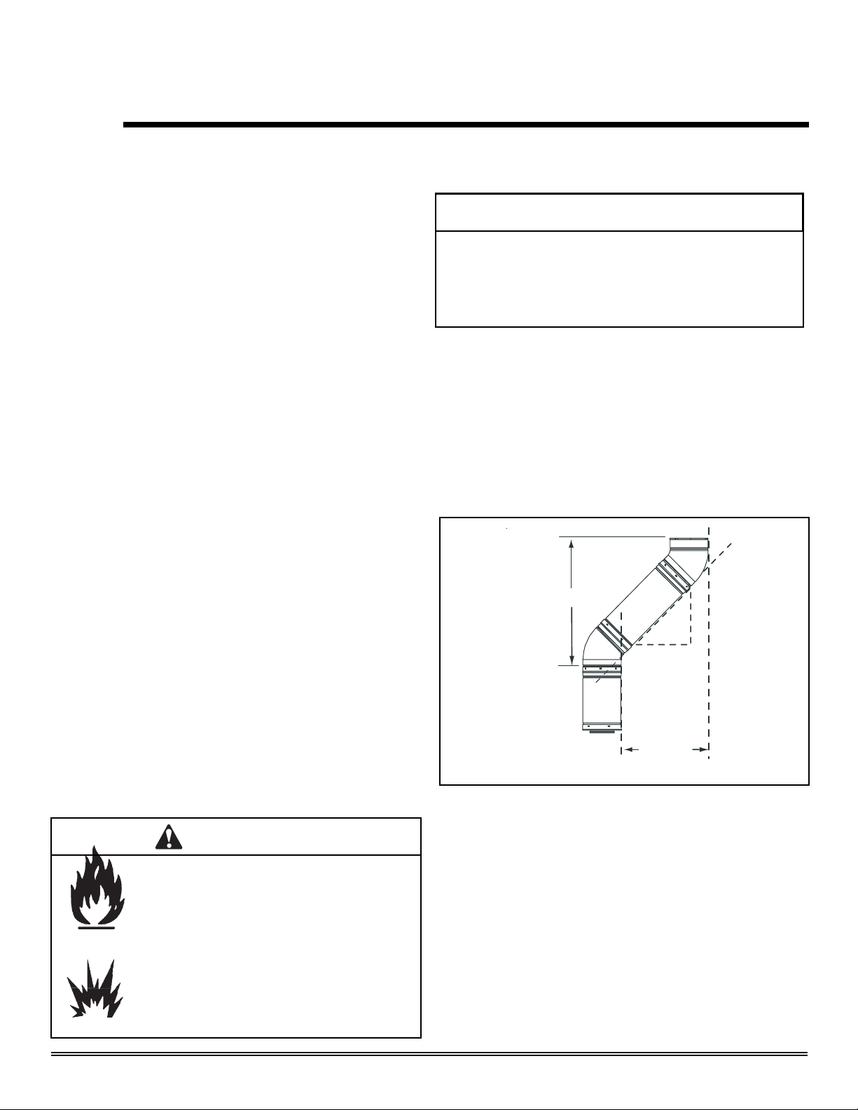
Diagonal runs have both vertical and horizontal vent aspects
when calculating the effects. Use the rise for the vertical aspect
and the run for the horizontal aspect. (See Figure 5.1.)
Two 45° elbows may be used in place of one 90° elbow . On 45°
runs, one foot of diagonal is equal to 8-1/2 in. (216mm) horizontal run and 8-1/2 in. (216mm) vertical run. A length of straight
pipe is allowed between two elbows. (See Figure 5.1.)
Vertical
12 in.
8-1/2 in.
8-1/2 in.
Horizontal
Figure 5.1
August 1, 2008
WARNING
Fire Hazard.
Explosion Risk.
Asphyxiation Risk.
Do NOT connect this gas appliance to a chimney
fl ue serving a separate solid-fuel or gas burning
appliance.
• Vent this appliance directly outside.
• Use separate vent system for this appliance.
May impair safe operation of this appliance or
other appliances connected to the fl ue.
Heat & Glo · Tiara I B & Tiara II B · 7010-149M
C. Measuring Standards
Vertical and horizontal measurements were made using the
following standards.
• Pipe measurements are from center line to center line.
• Horizontal terminations are measured to the outside of
the mounting surface (fl ange of termination cap). See
Figure 4.1 on page 9.
• Vertical terminations are measured to the top of the last
pipe before termination cap.
• Horizontal pipe installed level with 1/4 in. rise.
Page 11
Page 12
D. How to Use the Vent Graph E. Venting Guidelines
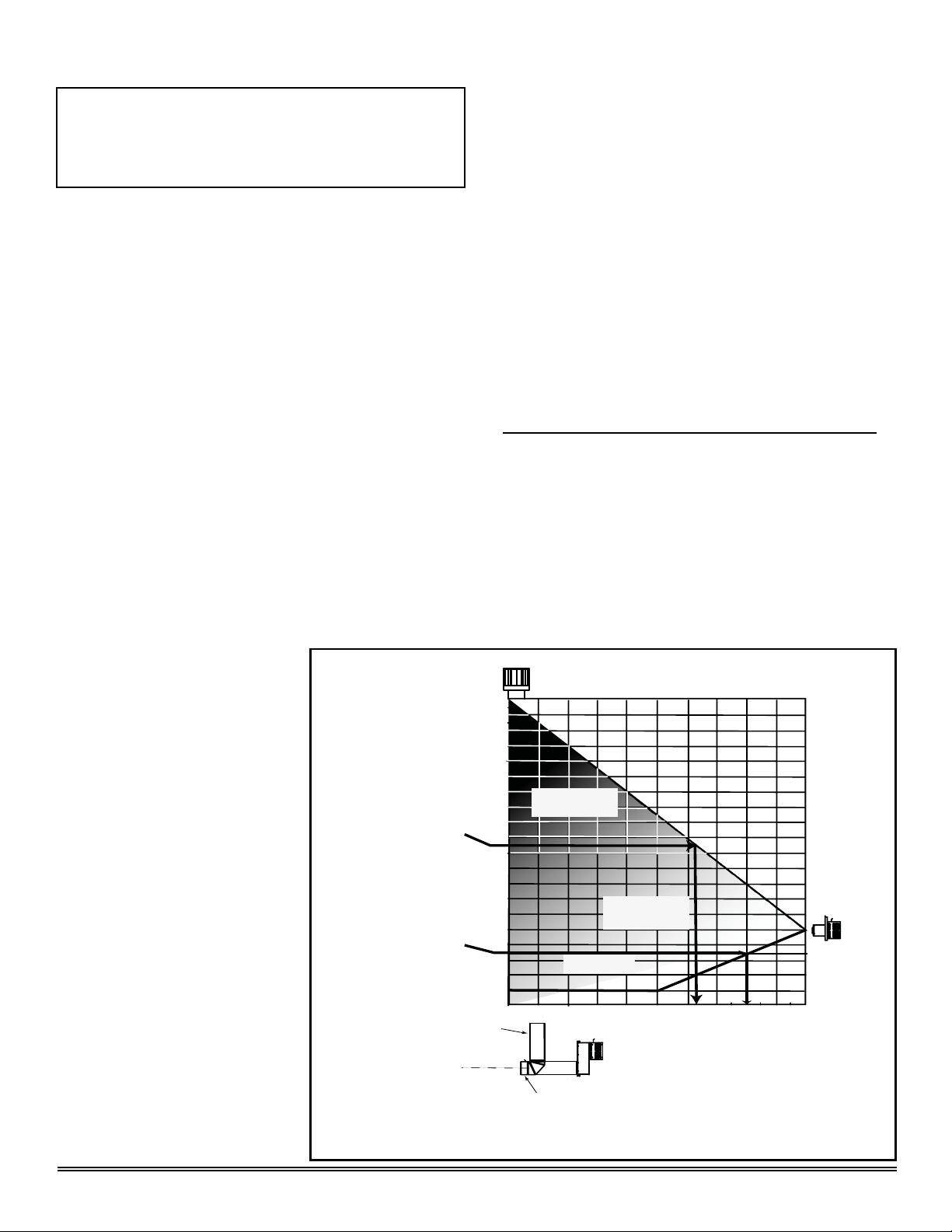
NOTE: IF YOUR INSTALLATION FALLS WITHIN A SHADED AREA ON
THE GRAPH, THE DAMPER MUST BE USED.* SEE INFORMATION ON
DAMPER ADJUSTMENT ON PAGE 31.
*In the Commonwealth of Massachusetts, the word damper shall be replaced
with the words flue restrictor.
1. Measure the distance from the top of appliance to the
center of the 90° elbow. On the graph below, draw a
horizontal line from that measurement on the vertical
axis across until it intersects with the slanted line.
2. From the point of this intersection, draw a vertical line to
the bottom of the graph.
3. The point at which this line meets the bottom line of the
graph is the maximum length of the horizontal run.
Example 1:
If the vertical dimension from the center line of
the fl ue vent to the center of the 90° elbow is 7 ft. (2m), the
horizontal run to the outer wall fl ange must not exceed 16
ft. (5m).
.
Example 2: If the vertical dimension from the center line of
the fl ue vent is 21 ft. (6m), the horizontal run to the outer wall
fl ange must not exceed 12 ft. 10 in. (4m).
4. Each 90° elbow is equivalent to 3 ft. (914mm) of vent
pipe and each 45° elbow is equivalent to 1 ft. (305mm)
of vent pipe, and must be subtracted from the vent pipe
run. A single horizontal to vertical 90° elbow is already
calculated into the allowable
20 ft. (6m) run. Each additional
90° elbow reduces the
maximum horizontal distance
40 ft. (12m)
Maximum V ertica l
by 3 ft. (914mm).
Example: The use of 3 elbows
would reduce the allowable
horizontal run to 9 ft. (3 -1 =
2 elbows x 3 ft. = 6 ft.; 20 ft.
max. - 6 ft. = 14 ft. max.).
VERTICA L DIS T ANCE
FROM APPLIANCE T O 90
ELBOW
Example 2
°
Example 1
• The maximum horizontal vent run is 20 ft. (6m) when the
vertical vent rise is 10 ft. (3m).
• The minimum horizontal vent run is 6 in. (152mm).
• Horizontal sections require a 1/4 in. (6mm) rise for every
12 in. (305 mm) of horizontal travel.
• Exterior Vent Diameter = 6-5/8 in. (168mm); Inner Vent
Diameter = 4 in. (102mm).
• Horizontal sections require noncombustible support
every 3 ft. (914mm), e.g. wall straps.
• For any vertical termination a minimum of 6 ft. (2m)
vertical must be used.
EXCEPTIONS FOR HORIZONTAL INSTALLATIONS:
*When installing the Tiara I-B or Tiara II-B in a rear vent
configuration with no vertical rise, a Snorkel Kit must be
used. Refer to venting components.
*The maximum horizontal vent run is 3 ft. (914mm).
*The maximum horizontal vent run with a 45° elbow is 2 ft.
(609mm).
*The minimum horizontal vent run is 6 in. (152mm).
Part #SLK-991DA
40'
39'
38'
37'
36'
35'
34'
32'
30'
28'
Damper position
26'
more CLOSED in
24'
22'
20'
18'
16'
14'
'
12
10'
8'
6'
4'
2'
this area
NO Damper in
this area
Damper position
more OPEN in
this area
SLK-01TRD
Page 12
6 ft. (2m) Minimum V ertical T erminatio n
C
C
For rear vent or top of
L
stove for top vent.
L
2' 4' 6 ' 8' 10' 12' 14' 15' 16' 17' 18' 19' 20'
6 in. (152mm) Minimum starter pipe
Figure 5.2
Heat & Glo · Tiara I B & Tiara II B · 7010-149M
3 ft. (914mm) Maximum Horizontal run with no vertical pipe
and with 1/4 in. (6mm) rise per foot. Must use Snorkel cap.
August 1, 2008
Page 13
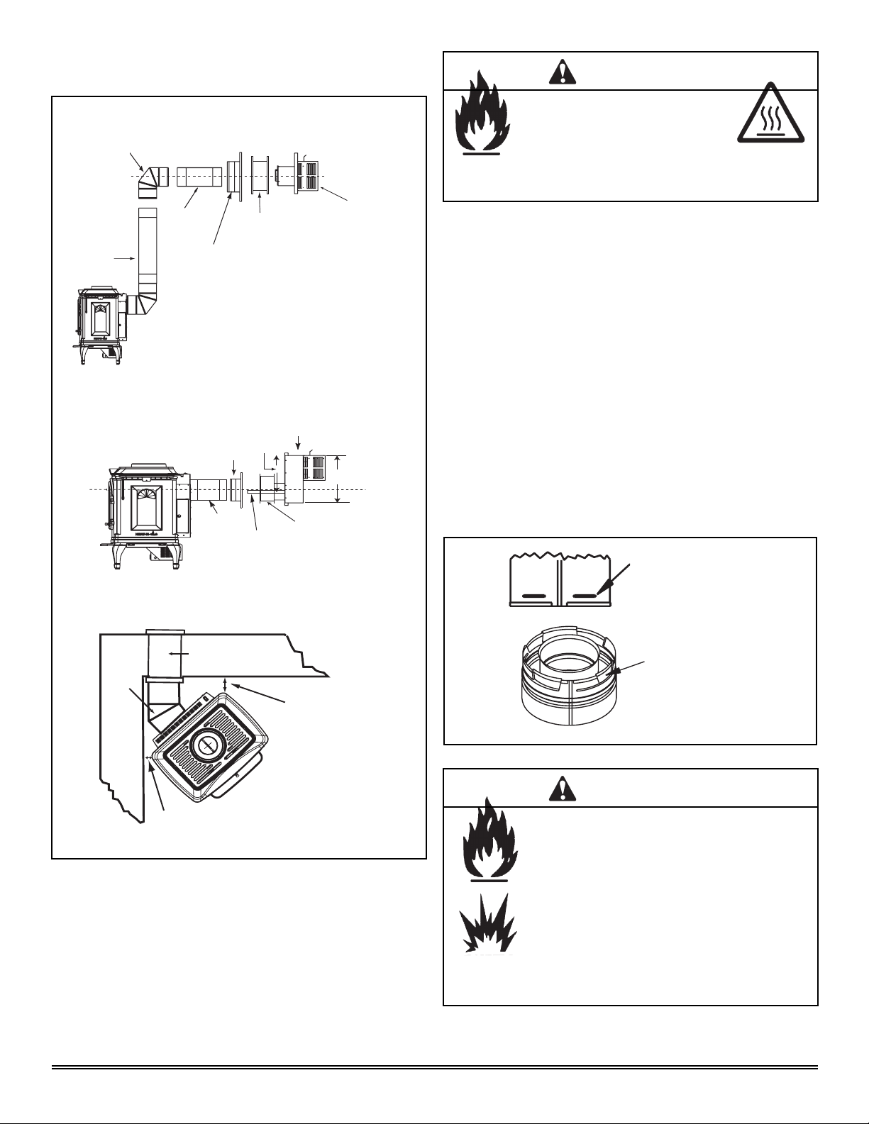
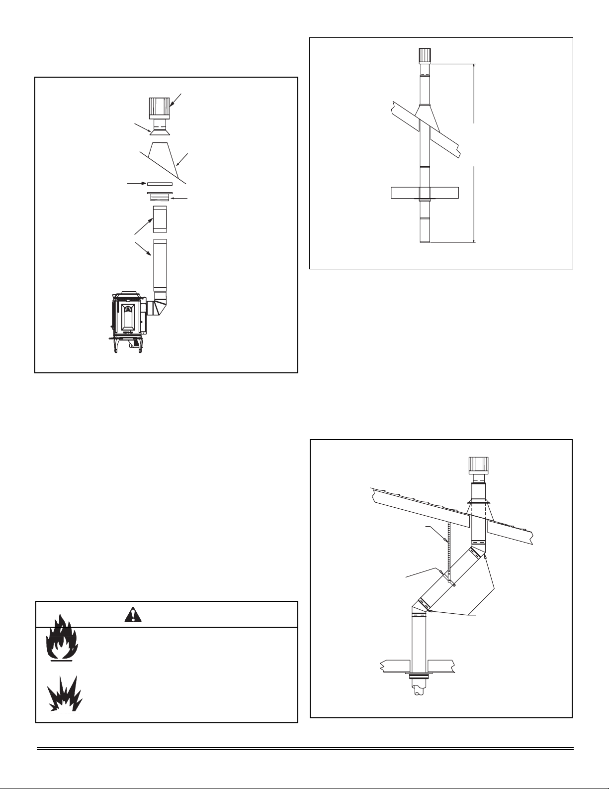
F. Horizontal Termination
Type A - Up & Out Installation
90° ELBOW
CENTER LINE
PIPE LENGTH
PIPE LENGTH
CENTER
LINE
Type B - Straight Out Installation
WALL THIMBLE COVER
WALL THIMBLE COVER
PIPE LENGTH
WALL STRAP 14 in. (356mm) Wide
WALL THIMBLE/
HEAT SHIELD
SNORKEL KIT
15-5/8 in.
(397mm)
TERMINATION CAP
21 in.
(533mm)
WALL THIMBLE / HEAT SHIELD
WARNING
Fire Hazard.
Exhaust Fume Risk.
Impaired Performance of Appliance.
• Ensure vent components are locked together correctly.
• Pipe may separate if not properly joined.
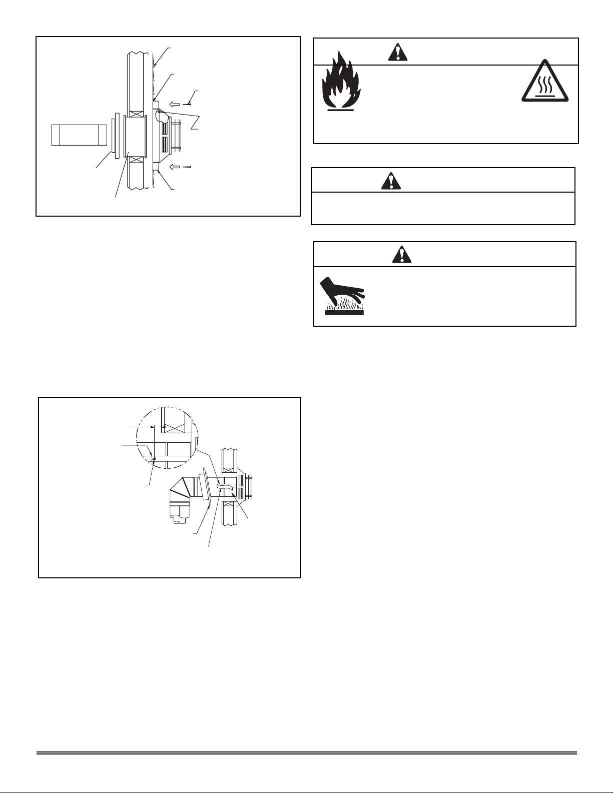
Step 2.
Direct vent pipe is designed with a locking connection. To
connect the venting system to the appliance flue outlet, a
twist-lock adapter is built into the appliance at the factory.
Wall thickness may vary . Remember to include wall thickness
in minimum clearances when figuring venting lengths for
your installation needs.
Note: Female ends of direct vent pipe/elbows are designed
to slide straight onto the male ends of adjacent pipes by
orienting the pipe indentations so they match and slide into
the entry slots on the male ends, see Figure 5.4. Push
the pipe sections completely together, then twist-lock one
section clockwise approximately one-quarter turn, until the
two sections are fully locked. The female locking lugs may
not be visible from the outside. They may be located by
examining the inside of the female ends.
Type C - 45° Elbow in Corner Installation
Wall Thimble/Heat Shield
45° Elbow
3/8 in. (10mm) Clearance from
stove corner to combustible wall.
3/8 in. (10mm)
Clearance from
stove corner to
combustible wall
(for valve access
on side).
Figure 5.3
Step 1.
Determine the desired location of the appliance. Check to
ensure that wall studs or roof rafters are not in the way when
the venting system is being planned. If this is the case, you
may want to adjust the location of the appliance.
Female Locking Lugs
Male Locking Lugs
Figure 5.4
WARNING
Fire Risk.
Explosion Risk.
Combustion Fume Risk.
Use vent run supports per installation instructions.
Connect vent sections per installation instructions.
• Maintain all clearances to combustibles.
• Do NOT allow vent to sag below connection
point to appliance.
• Maintain specifi ed slope (if required).
Improper support may allow vent to sag or separate.
August 1, 2008
Heat & Glo · Tiara I B & Tiara II B · 7010-149M
Page 13
Page 14
HOT
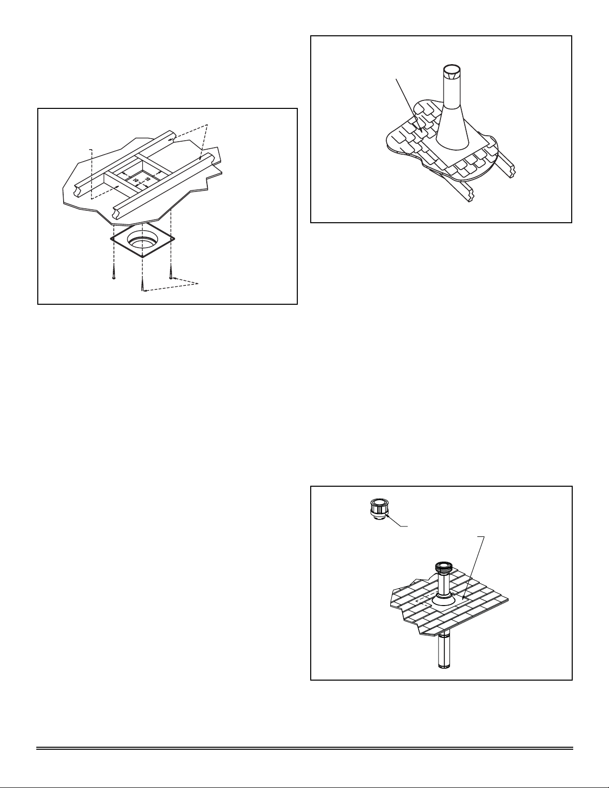
Step 3.
For installations using a round support box/wall thimble
(check pipe manufacturer's instructions), mark the wall for a
10 in. x 10 in. (254mm x 254mm) square hole. The center
of the square hole should line up with the center line of the
horizontal pipe, as shown in Figure 5.5. Cut and frame the
hole in the exterior wall where the vent will be terminated. If
the wall being penetrated is constructed of noncombustible
material, i.e. masonry block or concrete, a 7 in. (178mm)
diameter hole is acceptable.
CENTER OF
HOLE
Figure 5.6
HOT
WALL THIMBLE
WOOD
SCREW
CENTER
LINE
WALL
THIMBLE
Figure 5.5
CENTER
LINE
NOTE:
(1) Installation requires a minimum of 6 in. (152mm)
horizontal run of vent with a 1/4 in. (6mm) rise run towards
the termination. Each 1 ft. (305mm) of horizontal venting
must include a 1/4 in. (6mm) rise. Never allow the vent
to run downward. This could cause high temperatures
and may present the possibility of a fire.
(2) The location of the horizontal vent termination on an
exterior wall must meet all local and national building
codes, and must not be easily blocked or obstructed,
see Figure 4.4 on page 10.
NOTES:
(1) The four wood screws provided should be replaced with
appropriate fasteners for stucco, brick, concrete, or
other types of sidings.
(2) A termination cap with a built-in vinyl standoff is highly
recommended on a building with vinyl siding. The pilot
hole will be 2 in. (51mm) closer to the bottom of the
square than the top. Using a framing square, draw a 14
in. x 14 in. (356mm x 356mm) square around the pilot
hole. See Figure 5.7.
8 in.
(203mm)
7 in.
(178mm)
7 in.
(178mm)
6 in.
(152mm)
(3) For installations requiring a vertical rise on the exterior
of the building, a snorkel kit is available with a 14 in.
(356mm) and a 36 in. (914mm) tall snorkel termination
cap. Follow the same installation procedures as used
for standard horizontal terminations. If the snorkel
termination must be installed below grade (i.e. basement
application), proper drainage must be provided to
prevent water from entering the snorkel termination. Do
not backfill around snorkel termination.
Step 4.
Position the horizontal termination cap in the center of the 10
in. x 10 in. (254mm x 254mm) square hole and run a bead
of non-hardening mastic around its outside edges, so as to
make a seal between it and the wall, attach termination cap
to the exterior wall with the four wood screws provided. The
arrow on the vent cap should be pointing up (Figure 5.6).
Page 14
Heat & Glo · Tiara I B & Tiara II B · 7010-149M
Figure 5.7
(NOTE: Some termination caps may cause the vent
pipe to be off center on flashing.). Ensure that proper
clearances to combustible materials are maintained. If
you are not using an approved termination cap with a builtin standoff on a building with vinyl siding, a vinyl siding
standoff should be installed between the termination
cap and the exterior wall (Figure 5.8, on the next page).
Follow manufacturer’s instructions for attaching the
vinyl siding standoff to the horizontal termination cap.
The vinyl siding standoff prevents excessive heat from
possibly melting the vinyl siding material. The vent
terminal cap shall not be recessed into a wall or siding.
Remove siding from the area where the standoff will be
located.
August 1, 2008
Page 15
VINYL SIDING
WARNING
Apply sealant to all four sides
SCREWS
Bolt horizontal top to vinyl
standoff
WALL THIMBLE COVER
WALL THIMBLE
Figure 5.8
SCREWS
Vinyl siding standoff with siding beneath
removed
Step 5.
Place the wall thimble cover over the pipe assembly and
slide the appliance and vent assembly towards the wall,
carefully inserting the vent pipe into the vent termination
cap assembly. It is important that the vent pipe extend into
the vent termination cap a sufficient distance so as to result
in a minimum pipe overlap of 1-1/4 in. (32mm). Secure the
connection between the vent pipe and the vent termination
cap by attaching the two sheet metal strips extending from
the vent termination cap assembly into the outer wall of
the vent pipe. Use the two sheet metal screws provided to
connect the strips to the pipe section (Figure 5.9).
Fire Hazard.
Exhaust Fume Risk.
Impaired Performance of Appliance.
• Ensure vent components are locked together correctly.
• Pipe may separate if not properly joined.
WARNING
Do NOT connect a pipe section to a termination cap without
using the telescoping fl ue section found on the termination cap.
WARNING
Burn Risk.
• Local codes may require installation of a cap
shield to prevent anything or anyone from
touching the hot cap.
1/4 in. (6mm)
Fold Strap Here
Sheet Metal Screw
Wall Thimble
Figure 5.9
Wall Thimble Cover/Ceiling
Firestop as Required by Local
Jurisdiction
Strap
Note: The attachment from the vent pipe to the vent
termination cap must be sealed with silicone. Termination
caps shall not be recessed into a wall or siding.
August 1, 2008
Heat & Glo · Tiara I B & Tiara II B · 7010-149M
Page 15
Page 16
G. Vertical Termination
1. Direct Vent Pipe
VERTICAL
TERMINATION
CAP
STORM
COLLAR
FLASHING
FIRESTOP
SUPPORT
BOX
PIPE
LENGTH
Figure 5.10
Step 1.
Check the installation instructions for required 1 in. (25mm)
clearances (air space) to combustibles when passing through
ceilings, walls, roofs, enclosures, attic rafters, or other nearby
combustible surfaces. See page 17, Figure 5.15. Check the
instructions below for maximum vertical rise of the venting
system, and any maximum horizontal offset limitations. All
offsets must fall within the set parameters of the vent graph
(Figure 5.2) located on page 12.
35 ft. (11m)
MAXIMUM
Figure 5.11
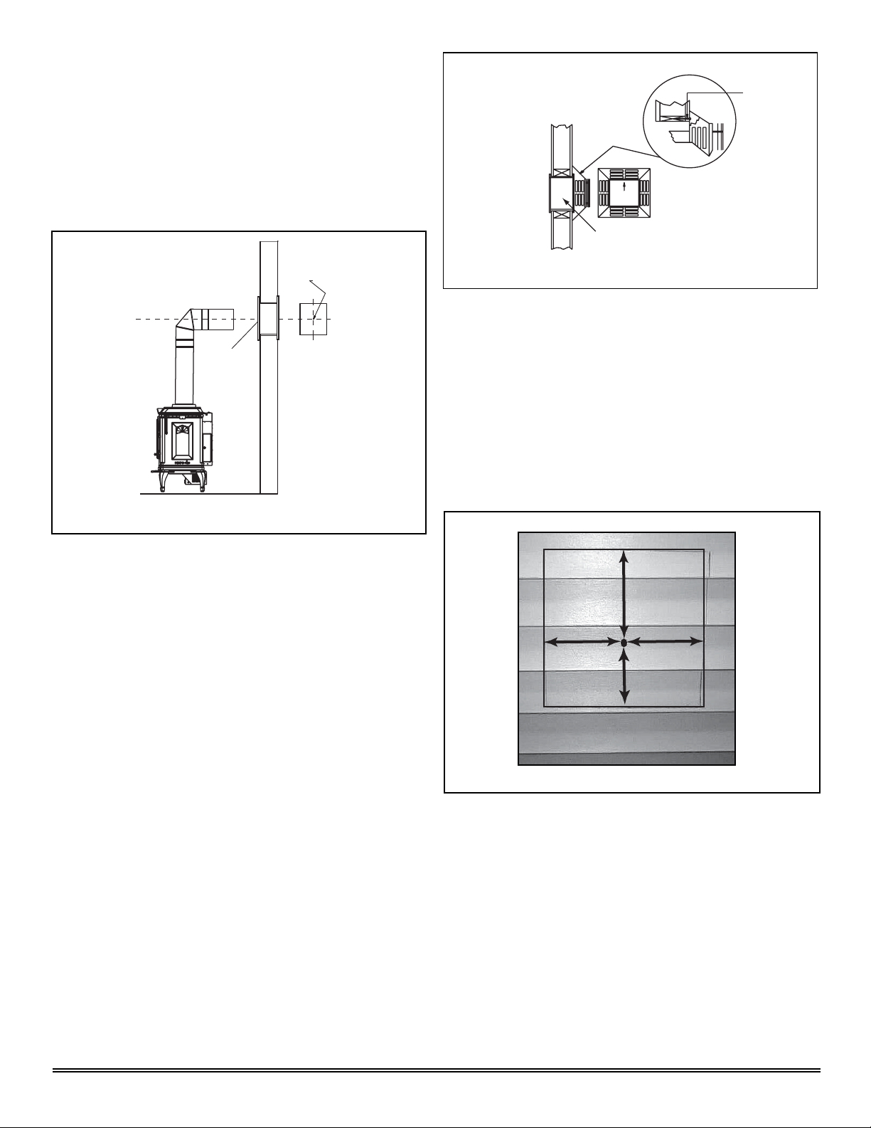
Step 2.
Set the gas appliance in its desired location. Drop a plumb
bob down from the ceiling to the position of the appliance
flue exit, and mark the location where the vent will penetrate
the ceiling. Drill a small hole at this point. Next, drop a plumb
bob from the roof to the hole previously drilled in the ceiling,
and mark the spot where the vent will penetrate the roof.
Determine if ceiling joists, roof rafters, or other framing will
obstruct the venting system. You may wish to relocate the
appliance, or to offset, as shown in Figure 5.12 to avoid
cutting loadbearing members.
NOTE: Maximum vertical rise allowable is 35 ft. (11m),
Figure 5.11.
NOTE: Maximum number of 45° elbows permitted for a
vertical installation is eight, provided their installation does
not decrease maximum allowable horizontal run (as specified
by vent graph, on page 12).
WARNING
Fire Risk.
Explosion Risk.
Maintain vent clearance to combustibles as speci-
fi ed.
• Do not pack air space with insulation or other
materials.
Failure to keep insulation or other materials away
from vent pipe may cause fi re.
Page 16
Heat & Glo · Tiara I B & Tiara II B · 7010-149M
Plumber’s Tape
connected to
Wall Strap
Wall Strap
Two 45˚ Elbows
Figure 5.12
August 1, 2008
Page 17
Step 3.
To install the round support box/wall thimble cover in a flat
ceiling, cut a 10 in. (254mm) square hole in the ceiling,
centered on the hole drilled in Step 2. Frame the hole as
shown in Figure 5.13.
Ceiling
Joists
Framing
Figure 5.13
Step 4.
Assemble the desired lengths of pipe and elbows necessary
to reach from the appliance up through the round support
box. Ensure that all pipe and elbow connections are in their
fully twist-locked position. Assemble as instructed.
Step 5.
Cut a hole in the roof centered on the small drill hole placed in
the roof in Step 2. The hole should be of sufficient size to meet
the minimum requirements for clearance to combustibles, as
specified. Continue to assemble lengths of pipe and elbows
necessary to reach from the ceiling support box/wall thimble
up through the roof line. Galvanized pipe and elbows may
be utilized in the attic, as well as above the roofline. The
galvanized finish is desirable above the roofline, due to its
higher corrosion resistance.
1 - 1/2 in. (38mm) Long
Wood Screws
Shingles overlap on
top edge of flashing
Figure 5.14
CAP AND STORM
COLLAR NOT SHOWN
FOR CLARITY
Step 7.
Continue to assemble pipe sections until the height of the
vent (before adding the termination cap) meets the minimum
code requirements as outlined in the current CAN/CGA-B149
Installation Codes (in Canada), the National Fuel Gas Code
NFPA 54/ANSI Z223.1 (in USA), or local codes. Note that
for steep roof pitches, the vent height must be increased.
See roof pitch table (Figure 4.3, on page 9). In high wind
conditions, nearby trees adjoining rooflines, steep pitched
roofs, and other similar factors can result in poor draft, or
down drafting. In these cases increasing the vent height or
switching to the high wind termination cap may solve this
problem.
Step 8.
Slip the storm collar over the pipe, and push it down to the
top of the flashing (Figure 5.15). Use non-hardening sealant
above and below the joint between the storm collar and the
pipe.
NOTE:
(1) If an offset is necessary in the attic to avoid obstructions,
it is important to support the vent pipe every 3 ft.
(914mm) to avoid excessive stress on the elbows, and
possible separation. Wall straps are available for this
purpose, Figure 5.12, page 16.
(2) Whenever possible, use 45° elbows, instead of 90°
elbows. The 45° elbow offers less restriction to the flow
of flue gases and intake air.
Step 6.
Slip the flashing over the pipe section(s) protruding through
the roof. Secure the base of the flashing to the roof with
roofing nails. Ensure the roofing material overlaps the top
edge of the flashing as shown in Figure 5.14. Verify that the
chimney is the required height above the roof. See roof pitch
table, Figure 4.3, on page 9.
August 1, 2008
Heat & Glo · Tiara I B & Tiara II B · 7010-149M
Optional High Wind Termination Cap
Secure Flashing with Non-Hardening
Sealant and Roofing Nails
Figure 5.15
Page 17
Page 18
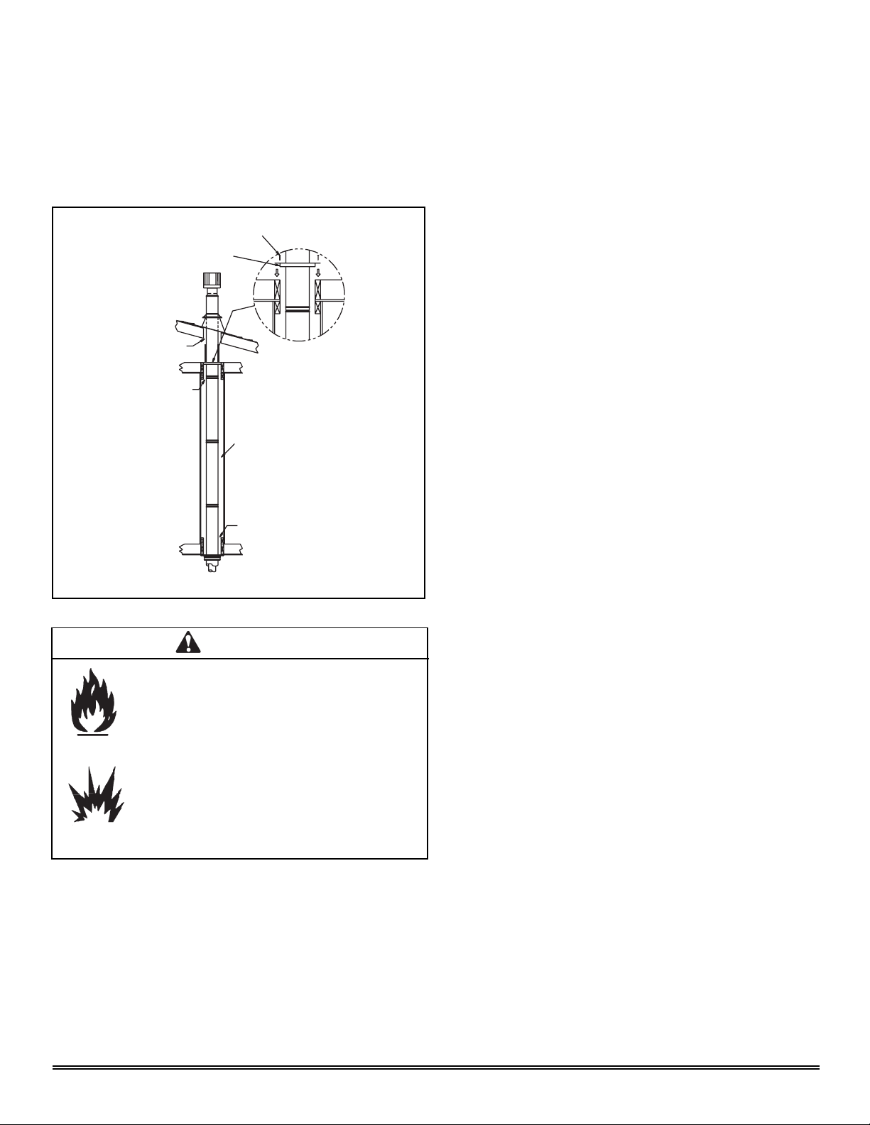
Step 9.
Twist-lock the vent cap and seal.
Note: For multi-story vertical installations, a ceiling firestop
is required at the second floor, and any subsequent floors
(Figure 5.16). The opening should be framed to 10 in. x
10 in. (254mm x 254mm) inside dimensions, in the same
manner as shown in Figure 5.13, on the previous page.
Nails
Ceiling Firestop
Minimum 1 in.
(24mm) Clearance
Minimum 1 in.
(24mm) Clearance
Minimum 1 in.
(24mm) Clearance
Figure 5.16
Minimum 1 in.
(24mm) Clearance
WARNING
Fire Risk.
Explosion Risk.
• Any occupied areas above the first floor, including
closets and storage spaces, which the vertical
vent passed through must be enclosed. The
enclosure may be framed and sheetrocked with
standard construction materials; however, refer
to these installation instructions for the minimum
allowable clearance between the outside of the
vent pipe and the combustible surfaces of the
enclosure. Do not fill any of the required air space
with insulation.
Page 18
Heat & Glo · Tiara I B & Tiara II B · 7010-149M
August 1, 2008
Page 19

2. Cathedral Ceiling
Step 1.
Follow installation Steps 1 and 2 under vertical installation
section, page 16.
Step 2.
Remove shingles or other roof covering as necessary to cut
the rectangular hole for the support box. Cut the hole 1/8 in.
(3mm) larger than the support box outline.
Step 3.
Lower the support box through the hole in the roof until the
bottom of the support box protrudes at least 2 in. (51mm)
below the ceiling (Figure 5.17). Align the support box both
vertically and horizontally with a level. Temporarily tack the
support box in place through the inside walls and into the
roof sheathing.
Figure 5.18
Level
Cathedral Ceiling
Support Box
2 in. (51mm)
Min. below
finished ceiling
Cut hole 1/8 in. (3mm)
greater in size than
pattern of support box
as it is projected onto
roof line
Figure 5.17
Step 4.
Using tin snips, cut the support box from the top corners
down to the roof line, and fold the resulting flaps over the
roof sheathing (Figure 5.18). Before nailing it to the roof,
run a bead of non-hardening mastic around the top edges
of the support box to make a seal between it and the roof.
Clean out any combustible material from inside the support
box.
Step 6.
Place the support clamp (provided with the support box)
inside the support box (at the bottom), and secure to the pipe
section. The clamp allows the support box to support the
weight of the pipe sections. Continue to add pipe sections
until you are above the roof line.
Step 7.
Complete the cathedral ceiling installation by following the
same procedures outlined in steps 7 through 9 for vertical
installations, pages 17-18.
Step 8.
Install the black trim collar around the outside of the cathedral
ceiling support box (Figure 5.19). The two pieces of the trim
collar slide over one another to allow for easy adjustment
around the support box. Using the six screws provided,
secure the four corners and the overlapping sections of the
trim collar to the ceiling. Y ou may want to predrill the holes for
the overlapped sections for ease of installation.
Trim Collar
Step 5.
Assemble the desired lengths of pipe and elbows necessary
to reach from the appliance up through the round support
box. Ensure that all pipe and elbow connections are in their
fully twist-locked position. Assemble as instructed.
August 1, 2008
Heat & Glo · Tiara I B & Tiara II B · 7010-149M
Figure 5.19
Cathedral
Ceiling
Support
Box
Screws
Page 19
Page 20

3. Class A Metal Chimney
EXISTING
METAL
CHIMNEY
SYSTEM
DIRECT VENT PIPE
Figure 5.20
TERMINATION
CAP
TOP
ADAPTOR
FLASHING
4 in. (102mm)
FLEX PIPE
RETRO CONNECTOR
Step 4.
Pass the flex pipe down through the center of the chimney
system, and center the top adapter on the top of the chimney
pipe. Drill four 1/8 in. (3mm) diameter holes through the
top adapter, and into the chimney top. Ensure that you are
drilling into the metal on the chimney. Twist lock the high
wind termination cap onto the top adapter (Figures 5.22
and 5.23).
Figure 5.22
CAUTION
Ensure that existing chimney is functionally sound and clean.
• Have inspection done by qualified chimney sweep or
professional installer BEFORE converting to direct vent
appliance.
Step 1.
Remove existing chimney cap.
Step 2.
Measure the distance from the top of the chimney to the
bottom of the ceiling support box, add 3 in. (76mm) to this
measurement, and cut a section of 4 in. (101mm) flex pipe
to that length (the flex should be fully extended).
Step 3.
Connect the end of the flex pipe section to the underside of the
top adapter, using four sheet metal screws (Figure 5.21).
Top Adapter
High Wind Termination
Cap
Sheet Metal Screws
Drill Four 1/8 in.
(3mm) Diamater
Holes
Figure 5.23
Step 5.
Pull the flex pipe down through the ceiling support box, until
it protrudes approximately 3 in. (76mm). Connect the flex
pipe to the retro connector, and attach with sheet metal
screws.
Figure 5.21
Page 20
Flex Pipe
Step 6.
Push the flex pipe back up into the ceiling support box,
center the retro connector, and attach it to the support box
Sheet Metal Screws
with sheet metal screws.
Step 7.
The connection between the appliance and the retro
connector may be completed with sections of direct vent
pipe.
Heat & Glo · Tiara I B & Tiara II B · 7010-149M
August 1, 2008
Page 21

4. Existing Masonry Chimney
m
e
w
n
e
Type A & B Co-Axial to Co-Linear
Co-Axial to
Co-Linear Connector
Pipe Length
Optional
Type C - Up & Out Installation
Chimney Liner
Termination Cap
3 in. (76m
Flex Lin
Showing t
30 ft.
(9m)Sectio
of Flex Lin
Chimney Liner
Termination Cap
30 ft. (9m) of 3 in.
(76mm) Flex Liner
Exhaust Section
This section of the
chimney must be
Co-Axial to Co-Linear
Connector
Pipe Length
Optional
*NOTE: In the Commonwealth of Massachusetts, the word damper shall
be replaced with the words fl ue restrictor.
sealed
The chimney must be
sealed from the 4 ft. (1m)
section to termination
using a smoke shelf or a
damper*. The seal
should be 6 in. (152mm)
below the end of the 4 ft.
(1m) Air Intake section.
4 ft. (1m) of 3 in. (76mm)
Flex Liner Air Intake Section
Type D - Hearth Mount
90° ELBOW
DIRECT
VENT PIPE
Figure 5.24
TOP ADAPTOR
RETRO
CONNECTOR
TERMINATION
FLASHING
4 in. (102mm)
FLEX LINER
CAP
Chimney Liner
Termination Cap
30 ft. (9m) of 3 in. (76mm)
Flex Liner Exhaust Section
This section of the
chimney must be sealed
Alcove Clearance to
Combustibles must be
maintained
Chimney must be sealed
from 4 ft. (1m) section to
termination using a smoke
shelf or a damper*. Seal
should be 6 in. (152mm)
below end of 4 ft. (1m) Air
Intake section.
4 ft. (1m) of 3 in.
Co-Axial to Co-Linear Connector
*NOTE: In the Commonwealth of Massachusettes, the word damper shall
be replaced with the words fl ue restrictor.
(76mm) Flex Liner
Air Intake Section
August 1, 2008
Heat & Glo · Tiara I B & Tiara II B · 7010-149M
Page 21
Page 22

CAUTION
Ensure that existing chimney is functionally sound and clean.
• Have inspection done by qualified chimney sweep or
professional installer BEFORE converting to direct vent
appliance.
Step 1.
Before cutting any holes, assemble the desired sections
of direct vent pipe to determine the center of the masonry
penetration.
Step 2.
Once the center point of the penetration has been determined,
cut a 6 in. (152mm) diameter hole in the masonry. If the hole
is too large, the retro connector might not mount properly; if
the hole is too small, the appliance might starve for intake
air. If there is a frame wall in front of the masonry wall, cut
and frame a 10 in. (254mm) square opening in the wall
(centered around the 6 in. (152mm) masonry opening). If
there is sheet rock only (no studs) in front of the masonry the
10 in. (254mm) opening is still needed, but does not need
to be framed. If the hole is framed a round support box/wall
thimble is required. This allows the retro connector to mount
directly on the masonry and provide the correct clearances
to combustibles (Figure 5.25).
Cut and bend flashing as needed
to fit
Sealant adhesive
Figure 5.26
Step 4.
To determine the length of flex needed, measure from 3 in.
(76mm) above the top of the flashing down to the level of the
opening. Add the distance from the center of the chimney
out through the wall. Cut a piece of 4 in. (102mm) flex to this
length (extended to its nominal length). Be sure to leave 2-3
in. (51-76mm) of flex above the existing chimney to allow for
connection to the termination kit.
Step 5.
Connect the flex liner to the top adapter using three sheet
metal screws (Figure 5.21 page 20).
Studwall
10 in. x 10 in. (254mm x 254mm)
framed opening in wall
Retro Connector
Wall Thimble Cover
(4) Masonry Bolts
(Not Included)
NOTE: For hearth applications refer to page 20, Figure 5.24 for
the use of a co-axial to co-linear appliance connector.
Figure 5.25
Masonry
Chimney
Step 3.
Secure the flashing to the top of the masonry chimney using
a bead of non-hardening sealant-adhesive. If the flashing is
larger than the top of the chimney, cut and fold flashing as
needed to fit chimney (Figure 5.26).
Step 6.
Feed the flex liner through the flashing into the chimney.
Carefully feed the flex liner down the chimney to the bottom
and out the opening in the masonry wall, forming an angle to
line up the flex liner with the vent opening on the appliance.
WARNING
Fire Risk.
Explosion Risk.
• Do not let the fl ex liner sag below the level at
which it will connect to the appliance or connector.
This could allow hot gas to become trapped and
potentially become a fi re hazard. The fl ex liner path
should always be sloped up toward the termination
cap.
Step 7.
If additional lengths of flex liner are needed to span the
chimney height, use a flex coupler to connect the pieces of
flex liner together. Connect the flex to the coupler by using
four sheet metal screws for each side (Figure 5.27, on the
next page).
Page 22
Heat & Glo · Tiara I B & Tiara II B · 7010-149M
August 1, 2008
Page 23

Flex Liner
Flex Coupler
Sheet Metal Screws
Figure 5.27
Step 8.
Secure the top adapter to the flashing. Use three sheet
metal screws through the side of the top adapter into the
flange on the flashing (Figure 5.28). Twist lock the high
wind termination cap on to the top adapter.
High Wind
Termination Cap
6 in. (152mm) diameter
opening in masonry wall
Retro Connector
(3) Masonry Bolts
(Not included)
Figure 5.29
Step 10.
Slide wall thimble cover over retro connector and secure
with masonry bolts (Figure 5.30). If you have a framed wall
in front of the masonry, use wood screws to mount wall
thimble cover to framed wall, over retro connector and 10
in. (254mm) square framed opening (Figure 5.25, page
22). If needed, add a section of direct vent pipe to the retro
connector in order to extend through the opening in the wall
thimble cover.
Top Adaptor
(3) Sheet Metal Screws
Flashing
Figure 5.28
Step 9.
Attach the flex to the retro connector. Use three sheet metal
screws to attach the flex liner to the connector (Figure
5.29). Mount the retro connector to the masonry wall using
masonry bolts. Redrill larger holes on connector as needed.
Be careful to ensure that the connector is centered in the
opening and the mounting holes line up with the masonry
wall.
Retro Connector
Wall Thimble Cover
(4) Masonry Bolts
(Not included)
Figure 5.30
Step 11.
The connection between the appliance and the retro
connector may be completed with sections of direct vent
pipe.
August 1, 2008
Heat & Glo · Tiara I B & Tiara II B · 7010-149M
Page 23
Page 24

Gas Information
6
A. Fuel Conversions
Before making gas connections ensure that the appliance
being installed is compatible with the available gas type.
Any natural or propane gas conversions necessary to meet
the appliance and locality needs must be made by a qualifi ed
technician using Hearth & Home Technologies specifi ed and
approved parts.
1. Converting to LP Gas
NOTE: Gas conversions should only be performed
by a qualified service person, and/or where required
by state and local codes, licensed installer/service
technician. In the Commonwealth of Massachusetts,
installation must be performed by a licensed plumber
or gas fitter.
KIT CONTENTS: Replacement orifi ce; replacement
pilot injector; valve regulator; conversion label.
Tiara II-B Burner Removal:
Figure 6.2 Using the #2 Phillips screwdriver remove the two
(2) 1/4" x 20 screws securing the burner as indicated. Lift
burner out of fi rebox.
TOOLS REQUIRED: Power drill (a 90° handle is helpful); #2 Phillips bit; 7/16” wrench,. slotted screwdriver
or Torx TH20, 5/32 in. Allen wrench, 5/8 in. open end
wrench,
Remove front (if installed), glass, and logs (if installed.)
Tiara I-B Burner Removal:
Figure 6.1 Remove the optional brick set, if installed. Remove
the two screws, one on
for reinstallation. Lift burner up and out of the fi rebox.
each side of burner. Retain fasteners
Figure 6.3 Remove the burner support by loosening the left
screw on the pilot tower, and removing the three screws on
the front side of the burner neck support.
Page 24
Slide the burner neck support to the left.
Heat & Glo · Tiara I B & Tiara II B · 7010-149M
August 1, 2008
Page 25

Tiara I-B and Tiara II-B:
MILLIVOT GENERATOR
PILOT HOOD
THERMOCOUPLE
Tiara I-B: Installation is the reverse of the removal. DO NOT
OVERTIGHTEN. Reinstall the optional brick set, if applica-
ble.
Tiara II-B: Installation is the reverse of the removal. Make
sure to reinstall the two 1/4 in. x 20 screws that secure the
burner.
Reinstall logs, glass and front.
Figure 6.4 Pull off pilot hood and set aside.
NOTE: Do not remove retaining clip from hood.
5/32 in. Allen wrench
Figure 6.5
tor.
Use a 5/32 in. Allen wrench to remove the pilot injec-
Replace pilot injector with the one supplied with the
appliance (#35 for Propane, #62 for Natural Gas).
Replace pilot hood, snapping into position.
2. Valve Regulator Replacement
WARNING
Fire Risk.
Explosion Risk.
• Disconnect any electrical cords and
turn off gas supply to unit before
proceeding if converting fuel on an
appliance already fully installed.
Remove upper and lower back shield. Loosen the set collars on the extension rods with the 3/32 in. Allen wrench.
Remove the rods and adapter cap.
Mounting Screws
1
2
Pressure Regulator Tower
3
Diaphragm
Figure 6.6 Remove main burner orifi ce using a 5/8 in. wrench.
Replace orifi ce with the proper size as indicated on for your
gas type and venting.
PROPANE NATURAL GAS
Tiara I-B .063 .106
Tiara II-B .073 .120
Reinstall burner by placing it into the fi rebox.
August 1, 2008
Heat & Glo · Tiara I B & Tiara II B · 7010-149M
Figure 6.6 Turn control knob to the OFF position, ensure that
gas supply to the valve has been turned off. Using a Torx
TH20, or slotted screwdriver, remove the three pressure
regulator mounting screws (1), pressure regulator tower (2),
and diaphragm (3).
Page 25
Page 26

E
B. Gas Pressures
Screws
Proper input pressures required for optimum appliance performance, gas line sizing requirements need to be followed
from NFPA51.
D
Rubber Gasket
Identification Label
Figure 6.7 Ensure that the rubber gasket (4) is properly posi-
F
tioned and install the new HI/LO pressure regulator assembly to the valve using the new screws (5) supplied with the
kit. Tighten screws securely. (Reference torque = 25 in./lb.)
Install the enclosed identifi cation label (6) to the valve body
where it can be seen.
Fill out the conversion label and attach it to the valve cover.
WARNING
Fire Risk.
Explosion Risk.
Gas Leak Risk.
• Rubber gasket must be seated properly on valve
face.
• Do no install a valve or regulator that has been
dropped.
WARNING
Fire Risk.
Explosion Risk.
• If the information in these instructions is
not followed exactly, a fi re, explosion or
production of carbon monoxide may result
causing property damage, personal injury
or loss of life.
• The qualifi ed service agency is responsible
for the proper installation of this conversion
kit. The installation is not proper and
complete until the operation of the converted
appliance is checked as specifi ed in the
manufacturer’s instructions supplied with
the kit.
WARNING
Fire Risk.
Explosion Hazard.
High pressure will damage valve.
• Disconnect gas supply piping BEFORE
pressure testing gas line at test pressures
above 1/2 psig.
• Close the manual shutoff valve BEFORE
pressure testing gas line at test pressures
equal to or less than 1/2 psig.
WARNING
Verify inlet pressures.
• High pressure may cause overfi re condition.
• Low pressure may cause explosion.
• Verify minimum pressures when other household
gas appliances are operating.
Install regulator upstream of valve if line pressure is
greater than 1/2 psig.
Pressure requirements for appliance are shown in the table
below. Minimum pressures must be met when other household gas appliances are operating.
PRESSURE NG LP
Minimum Inlet Pressure 5 inches w.c. 11 inches w.c.
Maximum Inlet Pressure 10 inches w.c. 13 inches w.c.
Manifold Pressure on “HI” 3.5 inches w.c. 10 inches w.c.
If the pressure is not suffi cient, ensure:
1) the piping used is large enough.
2) the supply regulator is adequately adjusted.
3) that the total gas load for the residence does not exceed
the amount supplied.
The supply regulator (the regulator that attaches directly to the
residence inlet or to the propane tank) should supply gas at
the suggested input pressure listed above. Contact the local
gas supplier if the regulator is at an improper pressure.
Page 26
Heat & Glo · Tiara I B & Tiara II B · 7010-149M
August 1, 2008
Page 27

C. Gas Connection
WARNING
NOTE: Have the gas supply line installed in accordance with
local building codes, if any . If not, follow ANSI Z223.1. Installation should be done by a qualifi ed installer approved and/or
licensed as required by the locality . (In the Commonwealth of
Massachusetts, installation must be performed by a licensed
plumber or gas fi tter.)
NOTE: A listed (and Commonwealth of Massachusetts
approved) 1/2 inch (13mm) T-handle manual shut-of f valve and
fl exible gas connector are connected to the 1/2 inch (13mm)
control valve inlet.
• If substituting for these components, please consult
local codes for compliance.
WARNING
Gas Leak Risk.
• Support control when attaching pipe to
prevent bending gas line.
NOTE: The gap between the supply piping and gas access
hole may be plugged with non-combustible insulation to prevent
cold air infi ltration.
Leak test all gas line joints and the gas control valve prior
to and after starting the appliance.
Before making the gas connection, ensure that the appliance
you are installing is designed for the type of gas being
supplied. This information can be found on the ratings label
under the appliance. If the appliance has been converted
to propane (LP), the valve cover should have a label stating
that the appliance has been converted to propane.
Connect the gas line at the 3/8 in. (10mm) pipe connector
on the valve at the back of appliance. We recommend
connecting the appliance with an approved flex gas line.
If flex gas lines are not approved in your area, you must
connect a hard pipe to the gas hookup.
You must supply a manual shut-off valve in a visible location
within 3 ft. (914mm) of the appliance.
Fire Risk or Explosion Hazard.
• Gas build-up during line purge may ignite.
• Purge should be performed by a qualifi ed
technician.
• Ensure adequate ventilation.
• Ensure there are no ignition sources such
as sparks or open fl ame.
A small amount of air will be in the gas supply lines. When
•
fi rst lighting appliance it will take a short time for air to
purge from lines. When purging is complete the appliance
will light and operate normally.
Air only needs to be purged again if gas valve has been
turned to the OFF position.
WARNING
CHECK FOR GAS LEAKS
Explosion Risk.
Fire Risk.
Asphyxiation Risk.
• Check the fi ttings and connections
• Do not use open fl ame.
• After the gas line installation is complete, all
connections must be tightened and checked
for leaks with a commercially-available, noncorrosive leak check solution. Be sure to rinse
off all leak check solution following testing.
Fittings and connections may have loosened during
shipping and handling.
WARNING
Fire hazard.
Do NOT change the valve settings.
• This valve has been preset at the factory.
• Changing valve settings may result in fi re
hazard or bodily injury.
HIGH ALTITUDE INSTALLATIONS
Omni-T est Laboratories, Inc. listed gas appliances are tested and
approved without requiring changes for elevations from 0 to 2000
feet in the U.S.A. and 0 to 4500 feet in Canada.
When installing this appliance at an elevation above 2000 feet,
it may be necessary to decrease the input rating by changing
the existing burner orifi ce to a smaller size. Input rate should be
reduced by 4% for each 1000 feet above a 2000 foot elevation
in the U.S.A. If the heating value of the gas has been reduced,
these rules do not apply. To identify the proper orifi ce size, check
with the local gas utility.
If installing this appliance at an elevation above 4500 feet (in
Canada), check with local authorities.
August 1, 2008
Heat & Glo · Tiara I B & Tiara II B · 7010-149M
Page 27
Page 28

7
This appliance is equipped with a three
pronged (grounding) plug for your protection
against shock hazard and should be plugged
directly into a prop
Electrical Information
A. Recommendation for Wire
See B5 below for recommended maximum lead length (two
wire) when using wall thermostat/switch.
NOTE: This appliance must be electrically wired and
grounded in accordance with local codes or, in the absence
of local codes, with National Electric Code ANSI/NFPA
70-latest edition or the Canadian Electric Code, CSA
C221.1.
B. Connecting to the Appliance
WARNING
Wire 110v to electrical junction box.
Do NOT wire 110v to the valve.
Do NOT wire 110V to wall switch.
• Incorrect wiring will damage millivolt
systems.
1. This appliance may be used with a wall switch, wall
mounted thermostat and / or a remote control.
8. Ensure the thermostat is mounted level for accurate
readings.
9. The thermostat should be mounted on an inside wall
and not in direct line with the appliance convection air.
10. If the thermostat is located too close to the appliance,
you may need to set the temperature setting slightly
higher to maintain the desired temperature in your
home.
Do not connect this appliance to a thermostat serving
any other appliance.
Bedroom installation in Canada requires this appliance
to be connected to a thermostat.
WARNING
Shock hazard.
•
This appliance is equipped with a three
pronged (grounding) plug for your protection
against shock hazard and should be plugged
directly into a properly grounded three prong
receptacle. Do not cut or remove the grounding
prong from this plug.
2. If using thermostat, use one compatible with a millivolt
gas valve system.
3. Follow parameters for locating thermostat (see individual thermostat instructions) to ensure proper operation
of appliance.
4. Use low resistance thermostat wire for wiring from ignition system to the wall switch and thermostat.
5. Use the following chart for wire sizing.
Wire Size Max. Length
16 gauge 65 feet
18 gauge 40 feet
20 gauge 25 feet
22 gauge 18 feet
6. Keep wire lengths as short as possible by removing
any excess wire length.
7. Low voltage and 110 VAC voltage cannot be shared
within the same wall box.
C. Standing Pilot Ignition System Wiring
This appliance DOES NOT require 110 VAC supply for
operation. A wiring diagram is shown in Figure 7.1 on the
next page.
This appliance is equipped with a millivolt control valve.
Page 28
Heat & Glo · Tiara I B & Tiara II B · 7010-149M
August 1, 2008
Page 29

O
F
F
P
I
L
O
T
O
N
TP
TH
TPTH
LO
HI
EA
P
I
L
O
T
IGNITON MODULE
THERMOPILE
GAS PILOT IGNITER
THERMOCOUPLE
PILOT ASSEMBLY
BLACK
ON / OFF SWITCH
BLACK
REMOTE SWITCH
Figure 7.1
CAUTION
Label all wires prior to disconnection when servicing controls.
Wiring errors can cause improper and dangerous operation.
Verify proper operation after servicing.
D. Ignition Module Access and Battery
Replacement
TPTH
TP
TH
VALV E
CAUTION
Shock hazard.
• Replace damaged wire with type 105O C
rated wire.
• Wire must have high temperature insulation.
The Ignition Module (automatic-ignitor) is located on the
side of the appliance. This module was incorporated into the
design of the Tiara I-B & II-B to facilitate "one hand" lighting
of the appliance. When the gas control knob is turned to
the "Pilot" position, and depressed, the ignitor should begin
sparking immediately. If the ignitor does not begin sparking
immediately, then it is in need of service.
Figure 7.2
August 1, 2008
The ignitor is located on a plate attached to the side of the
appliance using two #8 Phillips head screws. To access the
ignitor, remove the two screws securing the plate to the side
of the appliance and slide the plate out.
The single "AA" 1.5 V battery that powers the ignitor is
located in the module. To replace the battery, open the
battery compartment and remove old battery. Replace the
battery. Make sure the polarity is correct.
Heat & Glo · Tiara I B & Tiara II B · 7010-149M
Battery polarity must be correct or module damage will occur.
CAUTION
Page 29
Page 30

Appliance Setup
8
A. Remove Shipping Materials
Remove shipping materials from inside or underneath the
fi rebox.
B. Top to Rear Vent Conversion
TOOLS REQUIRED: Power drill; #2 Phillips bit; high-temp
sealant (optional).
Figure 8.3 Remove the inner collar adapter.
Figure 8.1 Remove top grille, as highlighted.
CAUTION
Sharp Edges
• Wear protective gloves
and safety glasses during
installation.
Figure 8.2 Remove vent pipe adapter and gasket by remov-
ing 8 screws. Save the screws. (If gasket breaks, apply
high-temp sealant to bottom of adapter before installing in
Figure 8.8.)
Screws
Figure 8.4 Locate the knock out on rear of appliance. Either
remove the four screws holding the back shield in place,
saving the screws, OR break the seal on the knock out and
discard the knock out.
Figure 8.5 Remove rear access plate and gasket. Save the
screws.
Screws
Rear plate
and gasket
Page 30
Heat & Glo · Tiara I B & Tiara II B · 7010-149M
August 1, 2008
Page 31

Figure 8.6 Place cover plate and gasket over top vent and
attach with the eight screws removed in Figure 8.2.
Figure 8.7 Insert inner collar adapter to rear fl ue vent.
C. Damper Adjustment
Refer to vent graph on page 12. If your installation falls
within the range of the gray shaded area of graph, it may be
necessary to make an adjustment to the vertical damper to
improve the flame appearance in your appliance.
1. Top Vent Installations
CLOSED
OPEN
Figure 8.9 Locate the damper adjustment on the intake
plenum, accessing through the appliance front. Adjustor is
centered at the top of the appliance.
1. Loosen screws using a Phillips head screwdriver.
2. Pivot the vertical damper adjustor in 1/4 in. (6mm)
increments while observing the activity.
3. Turn clockwise to open the damper = less fl ame height
and more blue in fl ame color.
4. Turn counterclockwise to close damper = increased
fl ame height and more yellow in fl ame color.
5. Make adjustment until fl ame size and activity suit your
personal preference and then retighten screws on the
adjustment control.
Figure 8.8 Install vent pipe adapter with gasket or high-temp
sealant to rear vent opening. Attach with screws removed
in Figure 8.5.
Place an appropriate grille (without a hole) gently into the
opening on top of appliance. (RV-GRILLE-T1 for the Tiara
I-B and RV-GRILLE-T2 for the Tiara II-B.)
2. Rear Vent Installations
Figure 8.10
the firebox (behind the rear brick panel on the Tiara II-B. It is
recommended to make adjustment prior to installation.
1. Remove front/glass/ logs and brick (if installed).
2. Loosen screws and slide up to suggested settings.
3. Tighten screws
4. Reinstall front/glass/logs and brick (if applicable).
NOTE: In the Commonwealth of Massachusetts, the word
damper shall be replaced with the words flue restrictor.
The rear vent damper is located in the back of
August 1, 2008
Heat & Glo · Tiara I B & Tiara II B · 7010-149M
Page 31
Page 32

D. Shutter Adjustment
OPEN
Figure 8.11 The shutter is located on the underside of the
CLOSE
appliance, on the right side. To adjust the shutter, loosen
the wingnut. Retighten the wingnut after adjustment.
Moving the shutter bolt to the right closes the shutter. Moving
the shutter bolt to the left, will open the shutter. Opening the
shutter causes f lames to bec ome shorter and blue. Closing
the shutter creates taller orange/yellow flames.
NOTE: Do not close so much as to cause a soot y flame.
Improper adjustment can cause sooting in the firebox and/or
on the outside of a house with a horizontal termination.
After adjustment, tighten nut to lock in place.
E. Leg Leveling System
Figure 8.14 Use a 5/32 in. (4mm) Allen wrench to adjust legs
up and down to desired level.
F. Installing the Baffl e - Tiara I-B
BAFFLE
BAFFLE RETAINERS
Figure 8.15 Position baffl e on top of baffl e retainers on left
and right sides. Centering baffl e on retainers, ensure that the
dark painted bevelled edge and darker painted baffl e bottom
side faces toward the front viewing area of the fi rebox. Bend
the center tabs up to prevent the baffl e from sliding out.
Figure 8.12 Thread Allen bolts through nuts until fl ush. The
Allen bolts and nuts are included in the component pack inside
the appliance fi rebox.
Figure 8.13 Slide assembled nuts and bolts into the slots on
the legs with the nuts on the bottom.
G. Brick Installation - Tiara II-B
NOTE: The brick supplied with the Tiara II-B is NOT an
optional accessory. The brick must be installed for safe and
proper operation.
REAR PANEL
Figure 8.16 Install rear panel by placing it behind the log pins
fl ush and centered against back of fi rebox.
Page 32
Heat & Glo · Tiara I B & Tiara II B · 7010-149M
August 1, 2008
Page 33

TABS
Figure 8.17 Install left and right side panels. Fold tabs over
on left and right sides to hold panels in place.
TOP PANEL/BAFFLE
H. Positioning the Logs - Tiara I-B
While breakable, the logs do not become fragile until after
the appliance is burned and they have cured. After curing,
any handling must be done with care as breakage may occur
easily.
PLEASE NOTE: Logs have been designed to work
specifically with the burners of the Tiara I-B and Tiara IIB. Exact placement will ensure proper operation of your
gas appliance and reduce sooting.
NOTCH
#1
LOCATING PINS
Figure 8.18 Install top panel/baffl e. If rear venting, set the
damper prior to installing top panel/baffl e. Holding panel at
an angle, place one end on top of side panel and lift other end
into place.
Figure 8.19 Complete brick installation.
Move left or right until centered.
TAB S
COMPLETED BRICK INSTALLATION
NOTE: In the Commonwealth of Massachusetts, the word
damper shall be replaced with the words flue restrictor.
Figure 8.20 Position rear log (#1) over the two locating pins.
#2
Figure 8.21 Put the right front log (#2) into place on the
burner. Lean the log back towards the rear log until it fi ts into
the notch in the rear log.
#1
August 1, 2008
#3
Figure 8.22 Place the left front log (#3) into place on the
burner. Log installation in complete.
Heat & Glo · Tiara I B & Tiara II B · 7010-149M
#2
Page 33
Page 34

I. Positioning the Logs - Tiara II-B K. Embers
Place individual pieces of embers in front of and around the
gas log where they can be seen. Space them so that gas can
contact them on all sides. Try to avoid stacking the embers
on top of each other. This will assure maximum brightness
#1
and effi cient use of the catalyst promoting brighter, cleaner
burning embers.
NOTE: Do not block gas ports.
Figure 8.23 Place rear log onto the two locating pins located
on the rear log shelf in the back of the fi rebox.
#1
#2
Figure 8.24 Place left and right logs into recesses cut out for
them on the left and right side of the burner. Log installation
is complete.
#3
J. Mineral Wool
WARNING
Explosion Risk.
• Follow ember placement instructions in
manual.
• Do NOT place embers directly over
burner ports.
• Replace ember material annually.
Improperly placed embers interferes with proper burner
operation.
L. Accessories
Install approved accessories per instructions included with
accessories. Refer to Section 12 for appropriate accessories.
WARNING
Shock or fi re risk.
Use ONLY optional accessories approved for
this appliance.
• Using non-listed accessories voids
warranty.
• Using non-listed accessories may result in a
safety hazard.
• Only Hearth & Home Technologies approved
accessories may be used safely.
Figure 8.25 Apply dime size pieces sparingly along front
edge of burner. Do not completely block ports.
Page 34
Heat & Glo · Tiara I B & Tiara II B · 7010-149M
August 1, 2008
Page 35

M. Optional Blower
KIT CONTENTS: Blower; speed control; lock nut; control
knob; ground clip; temperature sensor switch; wing nut; 2
high-temp black wires; 1 high-temp blue wire.
TOOLS REQUIRED: Philips head screwdriver; 1/2 in.
wrench.
The GFK-160A blower has been designed to circulate room
air through the appliance to enhance heat output.
The blower system operates on 120 V AC, 60 Hz power. This is
available through a receptacle in the factory installed junction
box on the underside of the appliance.
BLOWER
CONTROL
KNOB
GROUND
CLIP
CONTROL
TEMP.
SENSOR
SWITCH
NUT
SPEED
CONTROL
WING
NUT
Figure 8.28 Attach grounding clip supplied with the kit to the
blower housing. Attach ground wire to grounding clip.
WING NUT
Figure 8.29 Slide temperature sensor switch/bracket assembly
onto the 10-32 screw located on the left underside of the
appliance. Secure the bracket assembly with the wing nut
provided.
Disconnect the two wire ends connected together on the
junction box. Connect female end to one side of temperature
sensor switch.
Connect one end of the black wire provided with the kit to the
remaining wire end on junction box.
Figure 8.26 Compare CONTENTS OF CARTON with the
actual parts received. If any parts are missing or damaged,
contact your dealer before starting installation. Do not install
a damaged blower kit.
Figure 8.27 From the rear of the appliance, slide the blower
into the blower housing with the magnetic strips down. The
blower openings should be at the front.
Plug blower power cord into fan outlet on junction box.
Feed loose ends of the black and blue wires through the
orange grommet in fan housing.
3
SCREWS
Figure 8.30 Remove valve access cover from back of
appliance by removing the three screws indicated.
August 1, 2008
Heat & Glo · Tiara I B & Tiara II B · 7010-149M
Page 35
Page 36

SPEED CONTROL
LOCK NUT
AND STEM
Figure 8.31 Remove the knob and lock nut from the speed
control. Install speed control onto access panel with stem
sticking out the pre-punched hole. Attach the lock nut tightly
and reattach the knob on the stem.
Attach blue and black wires routed through orange grommet
in fan housing to the speed control. Reinstall access
panel.
VARIABLE SPEED CONTROL
BLACK
BLACK
JUNCTION BOX
BLACK
BLACK
TEMPERATURE SENSOR SWITCH
Figure 8.32
BLACK
BLACK
BLACK
BLACK
BLACK
BLACK
GROUND
GREEN
110 - 120 VAC
POWER SUPPLY
BLOWER RECEPTACLE
BLACK
WHITE
WHITE
BLOWER
WHITE
Page 36
Heat & Glo · Tiara I B & Tiara II B · 7010-149M
August 1, 2008
Page 37

N. Warming Shelves Installation
TOOLS REQUIRED: Phillips head screwdriver.
KIT CONTENTS: (2) Warming shelves, (2) brackets, and (4)
1/4 in. (Phillip head screws.
Figure 8.33 Remove warming shelves and hardware from
packaging. Install leveling screw to each warming shelf.
Figure 8.36 Align bracket to fi rebox and gently tighten the
screw to hold it in place. Reassemble the appliance.
O. Glass Replacement
1. Turn appliance OFF and let cool down before replacing
the glass.
2. Remove the front by lifting upwards 1/2 in. (13mm) and
away from the appliance.
3. Tiara I-B: Remove the glass door by opening the latches
located on both the left and right sides at the bottom of
the glass. Pull towards you and separate latches from
notches.
Figure 8.34 Install warming shelf bracket loosely to each
warming shelf using the screw provided.
Figure 8.35 Gently lift cast top off of appliance and set aside.
Install warming shelf to appliance gently aligning the shelf
with the tabs that are in place on the side of the appliance.
Use the leveling screw located in the center of the warming
shelf to adjust the shelf to its desired position.
Tiara II-B: Remove the glass door by opening the
latches located on both the left and right sides at the
top of the glass. Pull towards you and separate latches
from notches. Lift the glass out of the two notches at its
bottom and carefully set aside.
4. The new glass will come installed in a new glass frame.
Installation of the new glass and frame is the opposite
of the removal.
Reinstall appliance front.
5.
CAUTION
Handle glass assembly with care.
• Inspect the gasket to ensure it is undamaged.
• Inspect the glass for cracks, chips or
scratches.
• Do NOT strike, slam or scratch glass.
• Do NOT operate appliance with glass door
removed, cracked, broken or scratched.
• Replace glass assembly as a complete
assembly.
August 1, 2008
Heat & Glo · Tiara I B & Tiara II B · 7010-149M
Page 37
Page 38

Operating Instructions
9
A. Before Lighting Appliance
Read this entire manual prior to using the appliance.
Failure to follow the instructions may result in property
damage, bodily injury, or even death.
• Remove all shipping materials from inside and/or
underneath the fi rebox.
• Review proper placement of logs, mineral wool.
• Check the wiring.
• Check the baffl e adjustment.
• Ensure that there are no gas leaks.
• Ensure that the glass is sealed and in the proper posi-
tion.
• Ensure that the fl ow of combustion and ventilation air
is not obstructed (front grilles and vent caps).
WARNING
Improper installation, adjustment, alteration, service or
maintenance can cause injury or property damage. Refer to
the owner’s information manual provided with this appliance.
For assistance or additional information consult a qualifi ed
installer, service agency or the gas supplier.
WARNING
Do NOT use this appliance if any part has been under water.
Immediately call a qualifi ed service technician to inspect the
appliance and to replace any part of the control system and
any gas control which has been under water.
B. Controls
WARNING
Glass door must be in place when appliance is
operating.
Risk of:
• Combustion Fumes
• Fire
Do NOT operate appliance with glass door
removed.
• Open viewing glass for servicing only.
• Glass door MUST be in place and sealed before
operating appliance.
• Only use glass door certifi ed for use with appliance.
• Glass replacement should be done by qualifi ed
technician.
WARNING
HOT! DO NOT TOUCH.
SEVERE BURNS MAY RESULT.
CLOTHING IGNITION MAY RESULT.
Glass and other surfaces are hot
during operation and cool down.
• Keep children away.
• CAREFULLY SUPERVISE children in same room as
appliance.
• Alert children and adults to hazards of high temperatures.
• Do NOT operate with protective barriers open or removed.
• Keep clothing, furniture, draperies and other combustibles
away.
FAN SPEED: The blower is optional installed on the
appliance and this knob controls the speed of the blower
that pushes the heated air into the room.
MAIN BURNER: This control is used to turn the appliance
on and off.
PILOT IGNITOR: The pilot ignitor is used only to start
the pilot. When the valve control knob is turned to the
pilot position and fully depressed press the piezo ignitor
repeatedly creating a blue spark directly next to the pilot,
igniting the pilot flame.
VALVE CONTROL: This knob is used to control gas to
the appliance and for starting the pilot. There are three
positions, ON, OFF, & PILOT. The indicator on the valve
indicates the position of the knob.
COMFORT CONTROL: This knob controls the flame height
from low (“LO”) to high (“HI”).
NOTE: If using a remote control wall switch, or
thermostat, the On/Off Switch must be left “OFF”.
Turning the On/Off Switch to “ON” will keep the
appliance on continually.
Page 38
Heat & Glo · Tiara I B & Tiara II B · 7010-149M
August 1, 2008
Page 39

C. Lighting Appliance
FOR YOUR SAFETY READ BEFORE LIGHTING
LIGHTING INSTRUCTIONS
TO TURN OFF GAS TO APPLIANCE
FOR YOUR SAFETY READ BEFORE LIGHTING
WARNING: If you do not follow these instructions exactly, a fire or explosion may
result causing property damage, personal injury or loss of life
A. This appliance has a pilot that must be lit manually. When lighting the pilot, follow these instructions exactly.
B. BEFORE LIGHTING, smell around the appliance area for gas. Be sure to smell next to the floor because some gas is heavier
WHAT TO DO IF YOU SMELL GAS:
* Do not try to light any appliance.
* Do not touch any electric switch, do not use any phone in your building.
* Immediately call your gas supplier from a neighbor's phone. Follow the gas supplier's instructions.
* If you cannot reach your gas supplier, call the fire department.
C. Use only your hand to push in or turn the gas control knob. Never use tools. If the knob will not push in or turn by hand, don't
D. Do not use this appliance if any part has been under water. Immediately call a qualified service technician to
than air and will settle on the floor.
try to repair it, call a qualified service technician. Force or attempted repair may result in a fire or explosion.
and to replace any part of the control system and any gas control which has been under water.
inspect the appliance
LIGHTING INSTRUCTIONS
1. STOP! Read the safety information above on this label.
2. Set the thermostat to the lowest setting (if applicable) and turn off
the switch at the control panel.
3. Disconnect the power from the appliance.
4. Open the door of the appliance. May need to remove face/front first.
5. Push in gas control knob slightly and turn clockwise to the "OFF"
position. Do not force.
6. Wait five (5) minutes to clear out any gas. Smell for gas, including near the floor. If you smell gas, STOP! Follow "B" of the
safety information above. If you don't smell gas go to the next step.
7. Push gas control knob in and turn counterclockwise to the pilot position. NOTE: Knob cannot be turned unless knob is
pushed in slightly. Do not force.
8. PIEZO IGNITER:
(This may take many repetitions for lighting.)
ELECTRONIC IGNITER: If the unit is equipped with an electronic igniter it should begin sparking right away.
9. The pilot should be visible through the door opening.
10. After the pilot is lit, continue holding control knob down for approximately
30 seconds. Release the knob and it will pop back up. Pilot should remain lit.
If it goes out, repeat steps 7 through 9.
* If the knob does not pop up when released, stop and immediately call your
service technician or gas supplier.
* If the pilot will not stay lit after several tries, turn the gas control knob
clockwise to "OFF" and call your service technician or gas supplier.
11. Reinstall door and face. Wait five minutes to allow pilot flame to stabilize and
establish proper draft.
12. Push down and turn gas control knob counterclockwise to "ON".
13. Push burner rocker switch on the control panel to "ON". If thermostat is to be used, leave switch in "OFF" position and set the
thermostat to desired setting.
14. Reconnect electrical power to appliance.
Press down on the gas control knob in pilot position and simultaneously press the piezo igniter.
MILLIVOLT
GENERATOR
PILOT HOOD
THERMOCOUPLE
TO TURN OFF GAS TO APPLIANCE
1. Set the thermostat to lowest setting.
2. Turn off all electric power to the appliance if service is to be performed.
3. Push in gas control knob slightly and turn clockwise to "OFF" position.
August 1, 2008
Heat & Glo · Tiara I B & Tiara II B · 7010-149M
Page 39
Page 40

D. After Appliance is Lit
Initial Break-in Procedure
When you light your appliance, you may notice that it produces heat which does have an associated odor or smell. If
you feel this odor is excessive it may require the initial three
to four hour continuous burn on high followed by a second
burn up to 12 hours to fully drive off any odor from paint and
lubricants used in the manufacturing process. Condensation
on the inside of the glass is normal.
NOTE: The appliance should be run three to four hours
on the initial start-up. Turn it of f and let it cool completely.
Remove and clean the glass. Replace the glass and
run the appliance for an additional 12 hours. This will
help to cure the products used in the paint and logs.
During this break-in period it is recommended that some
windows in the house be opened for air circulation. This will
help avoid setting off smoke detectors, and help eliminate
any odors associated with the appliance’s initial burning.
WARNING
Fire Risk.
High Temperatures.
Keep combustible household items away from appliance.
Do NOT obstruct combustion and ventilation air.
• Do NOT place combustible items on top of or in front of
appliance.
• Keep furniture, draperies away from appliance.
CAUTION
• Prevent accidental appliance operation when not
attended.
• Unplug or remove batteries from remote control if absent
or if appliance will not be used for an extended period
of time.
• Property damage possible from elevated temperatures.
CAUTION
Smoke and odors released during initial operation.
• Open windows for air circulation.
• Leave room during initial operation.
• Smoke may set off smoke detectors.
Smoke and odors may be irritating to sensitive
individuals.
WARNING
Fire Hazard.
Keep combustible materials, gasoline
and other fl ammable vapors and liquids
clear of appliance.
• Do NOT store fl ammable materials in the appliance’s
vicinity.
• Do NOT use gasoline, lantern fuel, kerosene, charcoal
lighter fl uid or similar liquids in this appliance.
• Combustible materials may ignite.
E. Frequently Asked Questions
ISSUE SOLUTIONS
Condensation on the glass This is a result of gas combustion and temperature variations. As the appliance warms,
this condensation will disappear.
Blue fl ames This is a result of normal operation and the fl ames will begin to yellow as the appliance
is allowed to burn for 20 to 40 minutes.
Odor from appliance When fi rst operated, this appliance may release an odor for the fi rst several hours.
This is caused by the curing of the paint and the burning off of any oils remaining from
manufacturing. If appliance has not been used for some time, dust can build up and
cause an odor.
Film on the glass This is a normal result of the curing process of the paint and logs. Glass should be
cleaned within 3 to 4 hours of initial burning to remove deposits left by oils from the
manufacturing process. A non-abrasive cleaner such as gas appliance cleaner may be
necessary. See your dealer.
Metallic noise Noise is caused by metal expanding and contracting as it heats up and cools down,
similar to the sound produced by a furnace or heating duct. This noise does not affect
the operation or longevity of the appliance.
Page 40
Heat & Glo · Tiara I B & Tiara II B · 7010-149M
August 1, 2008
Page 41

Troubleshooting
10
With proper installation, operation, and maintenance your gas appliance will provide years of trouble-free service. If you do
experience a problem, this troubleshooting guide will assist a qualifi ed service person in the diagnosis of a problem and the
corrective action to be taken. This troubleshooting guide can only be used by a qualifi ed service technician.
Symptom Possible Cause Corrective Action
1. After repeated triggering of the piezo
button, the spark ignitor
will not light the pilot.
2. The pilot will not stay
lit after carefully following the lighting instructions.
a. Defective ignitor. Check the spark at the electrode and pilot. If no spark and electrode
wire is properly connected, replace the ignitor.
b. Defective pilot or
misaligned electrode
(spark at electrode).
c. No gas or low gas
pressure.
d. No LP in tank. Check the LP (propane) tank. You may be out of fuel.
a. Defective thermo-
couple.
Using a match, light the pilot. If the pilot lights, turn off the pilot and
trigger the piezo button again. If the pilot lights, an improper gas/air
mixture caused the bad lighting and a longer purge period is recommended. If the pilot will not light, ensure the gap at the electrode and
pilot is one-eighth (1/8) inch to have a strong spark. If the gas is OK,
replace the pilot.
Check the remote shut-off valve from the appliance. Usually, there is
a valve near the gas main. There can be more that one (1) valve from
the appliance and the main.
Check that the pilot fl ame impinges on the thermocouple. Clean and /or
adjust the pilot for maximum fl ame impingement.
Ensure that the thermocouple connection at the gas valve is fully
inserted and tight (hand tighten plus 1/4 turn).
3. The pilot is burning,
there is no gas to the
burner, the valve knob is
in the ON position, and
the ON/OFF switch is in
the ON position.
Disconnect the thermocouple from the valve, place one millivolt lead
wire on the tip of the thermocouple and the other meter wire on the
thermocouple copper lead. Start the pilot and hold the valve knob in. If
the millivolt reading is less than 15mV, replace the thermocouple.
b. Defective valve. If the thermocouple is producing more than 15 millivolts, replace faulty
valve.
a. ON/OFF switch or
wires defective.
b. Thermopile may
not be generating
suffi cient millivoltage.
Check the ON/OFF switch and wires for proper connections. Place the
jumper wires across the terminals at the switch. If the burner comes on,
replace the defective switch. If the switch is OK, place the jumper wires
across the switch wires at the gas valve. IF the burner comes on, the
wires are faulty or connections are bad.
If the pilot fl ame is not close enough physically to the thermopile, adjust
the pilot fl ame.
Be sure the wire connections from the thermopile at the gas valve terminals are tight and that the thermopile is fully inserted into the pilot
bracket.
Check the thermopile with a millivolt meter. Take the reading at THTP&TP terminals of the gas valve. The meter should read 325 millivolts
minimum, while holding the valve knob depressed in the pilot position,
with the pilot lit, and the ON/OFF switch in the OFF position. Replace
the faulty thermopile if the reading is below the specifi ed minimum.
With the pilot in the ON position, disconnect the thermopile leads from
the valve. Take a reading at the thermopile leads. The reading should
be 325 millivolts minimum. Replace the thermopile if the reading is
below the minimum.
August 1, 2008
Heat & Glo · Tiara I B & Tiara II B · 7010-149M
Page 41
Page 42

Symptom Possible Cause Corrective Action
3. (Continued) c. Defective valve. Turn the valve knob to the ON position. Place the ON/OFF switch in the
ON position. Check the millivolt meter at the thermopile terminals. The
millivolt meter should read greater than 125mV . If the reading is acceptable, and if the burner does not come on, replace the gas valve.
d. Plugged burner
orifi ce.
e. Wall switch or
wires are defective.
4. Frequent pilot outage
problem.
a. Pilot fl ame may
be too high or too
low, or blowing
(high), causing safety
pilot to drop out.
5. The pilot and main
burner extinguish while
in operation.
a. No LP in tank. Check the LP (propane) tank. Refi ll the fuel tank.
b. Inner vent pipe
leaking exhaust
gases back into the
system.
c. Horizontal vent
improperly pitched.
d. Bad thermopile or
thermocouple.
e. Improper vent cap
installation.
6. Glass soots. a. Flame impinge-
ment.
b. Improper shutter
setting.
c. Debris around
opening at base of
burner.
7. Flame burns blue
and lifts off burner.
a. Insuffi cient
oxygen being supplied.
Check the burner orifi ce for stoppage. Remove stoppage.
Follow the corrective action in Symptom and Possible Cause 1.a.
Check the switch and wiring. Replace where defective.
Clean and adjust the pilot fl ame for maximum fl ame impingement on
thermocouple. Follow lighting instructions carefully.
Check for proper vent connection at fl ue collar and all vent joints.
The horizontal vent cap should slope down only enough to prevent any
water from entering the appliance.
Replace if necessary.
Check for proper installation and freedom from debris or blockage.
Adjust the log set so that the fl ame does not excessively impinge on it.
Check that logs are placed according to installation instructions.
Adjust the air shutter at the base of the burner.
Inspect the opening at the base of the burner. NO MATERIAL SHOULD
BE PLACED IN THIS OPENING.
Ensure that the vent cap is installed properly and free of debris. Ensure
that the vent system joints are tight and have no leaks.
Ensure that no debris has been placed at the base of, or in the area of
the air holes in the center of the base pan beneath the burner.
Page 42
Ensure that the glass is tightened properly on the appliance, particularly on top corners.
Heat & Glo · Tiara I B & Tiara II B · 7010-149M
August 1, 2008
Page 43

Maintaining and Servicing Appliance
11
Although the frequency of your appliance servicing and
maintenance will depend on use and the type of installation,
a qualifi ed service technician should perform an appliance
check-up at the beginning of each heating season.
WARNING
Risk of injury or property damage.
Before servicing:
• Turn off gas.
• Turn off electricity to appliance.
• Ensure appliance is completely cooled.
After servicing:
• Replace any screen or barrier that was removed.
• Reseal and reinstall any venting removed for servicing.
WARNING
Annual inspection by qualifi ed technician recommended.
Check:
• Condition of glass, glass assembly and glass seal.
• Obstructions of combustion and ventilation air.
• Obstructions of termination cap.
• Burner ignition and operation.
• Burner air shutter adjustment
• Gas connections and fi ttings.
Clean:
• Glass
• Air passageways, grilles,
control compartment
• Burner, burner ports
Risk of:
• Fire
• Delayed ignition or explosion
• Exposure to combustion fumes
• Odors
CAUTION
Handle glass assembly with care.
NOTE: Clean glass after initial 3-4 hours
operation. Longer operation without cleaning
glass may cause a permanent white fi lm on
glass.
When cleaning glass door:
• Avoid striking, scratching or slamming glass.
• Do NOT use abrasive cleaners.
• Use a hard water deposit glass cleaner on white fi lm.
• Do NOT clean glass when hot.
• Turn off appliance after 3-4 hours of operation and ALLOW
TO COOL.
• Remove and clean glass assembly.
• Replace glass assembly and operate appliance for
additional 12 hours.
Refer to maintenance instructions.
August 1, 2008
WARNING
Inspect external vent cap regularly.
• Ensure no debris blocks cap.
• Combustible materials blocking cap
may ignite.
• Restricted air fl ow affects burner
operation.
Heat & Glo · Tiara I B & Tiara II B · 7010-149M
Page 43
Page 44

A. Maintenance Tasks
Inspect Maintenance Tasks
Doors 1. Inspect for scratches, dents or other damage and repair as necessary.
2. Verify no obstructions to air fl ow.
3. Verify maintenance of proper clearance to combustible household objects.
Gasket Seal, Glass
Assembly and Glass
Valve Compartment
and Firebox Top
Logs 1. Inspect for broken, damaged, or missing logs. Replace as necessary.
Firebox 1. Inspect for paint condition, warpage, corrosion or perforation. Sand and repaint as neces-
Burner Ignition and
Operation
Venting 1. Inspect venting for blockage or obstruction such as bird nests, leaves, etc.
Remote Controls 1. Verify operation of remote.
1. Inspect gasket seal and its condition.
2. Inspect glass for scratches and nicks that can lead to breakage when exposed to heat.
3. Confi rm there is no damage to glass or glass frame, Replace as necessary.
4. Verify that latches engage properly and glass attachment components are intact and operating properly. Replace as necessary.
5. Clean glass. Replace glass assembly if severely coated with silicate deposits that cannot
be removed.
1. Vacuum and wipe out dust, cobwebs, debris or pet hair. Use caution when cleaning these
areas. Screw tips that have penetrated the sheet metal are sharp and should be avoided.
2. Remove any foreign objects.
3. Verify unobstructed air circulation.
2. Verify correct log placement and no fl ame impingement causing sooting. Correct as neces-
sary.
sary.
2. Replace appliance if fi rebox has been perforated.
1. Verify burner is properly secured and aligned with pilot or igniter.
2. Clean off burner top, inspect for plugged ports, corrosion or deterioration. Replace burner if
necessary. USE CAUTION WHEN CLEANING/HANDLING CERAMIC BURNER.
3. Replace ember material with new dime-size and shape pieces. Do not block ports or obstruct
lighting paths.
4. Check for smooth lighting and ignition carryover to all ports. Verify there is no ignition
delay.
5. Inspect for lifting and other fl ame problems.
6. Inspect orifi ce for soot, dirt or corrosion.
7. Verify manifold and inlet pressures. Adjust regulator as required.
8. Inspect pilot fl ame strength. Clean or replace orifi ce as necessary.
9. Inspect thermocouple/thermopile sensor rod for soot, corrosion and deterioration. Clean with
emery cloth or replace as required.
10. Verify millivolt output. Replace as necessary.
2. Confi rm that termination cap remains clear and unobstructed by plants, etc.
3. Verify that termination cap clearance to subsequent construction (building additions, decks,
fences or sheds) has been maintained.
4. Inspect for corrosion or separation.
5. Verify weather stripping, sealing and fl ashing remains intact.
2. Replace batteries in remote transmitters and battery-powered receivers.
Page 44
Heat & Glo · Tiara I B & Tiara II B · 7010-149M
August 1, 2008
Page 45

Reference Materials
12
A. Appliance Dimension Diagram - Tiara I-B
Dimensions are actual appliance dimensions. Use for reference only. For clearances to combustibles refer to Section 3.
NOTE: Diagrams show gas appliance equipped with optional Blower, Part #GFK-160A.
A
B
C
E
Location Inches Millimeter Location Inches Millimeter
A 35-1/2 902 E 20-1/4 514
B 23-1/4 590 F 11-3/4 298
C 9-3/8 237 G 20 506
D 27 686
Figure 12.1 Appliance Dimensions
D
F
C
L
G
August 1, 2008
Heat & Glo · Tiara I B & Tiara II B · 7010-149M
Page 45
Page 46

B. Appliance Dimension Diagram - Tiara II-B
Dimensions are actual appliance dimensions. Use for reference only. For clearances to combustibles refer to Section 3.
NOTE: Diagrams show gas appliance equipped with optional Blower, Part #GFK-160A.
A
B
C
E
Location Inches Millimeter Location Inches Millimeter
A 41-3/4 1060 E 22-1/4 565
B 29-1/2 749 F 14-3/4 375
C 9-1/2 240 G 22-1/4 565
D 29-1/4 743
Figure 12.2 Appliance Dimensions
D
F
C
L
G
Page 46
Heat & Glo · Tiara I B & Tiara II B · 7010-149M
August 1, 2008
Page 47

C. Vent Components Diagram
9-1/4 in.
(235mm)
SLP45-BK
6-1/2 in.
(165mm)
6-5/8 in.
(168mm)
6-3/8 in.
(162mm)
6-5/8 in.
(168mm)
6-3/8 in.
(162mm)
SLP90M
6-1/2 in.
(165mm)
9-5/8 in.
(244mm)
9-5/8 in.
(244mm)
17-24 in.
(432-610mm)
3-3/4 in.
(95mm)
SLP12AM
12-17 in.
(305-432mm)
11-3/4 in.
(298mm)
SLP12M
23-3/4 in.
(603mm)
6-1/2 in.
(165mm)
5-3/4 in.
(146mm)
6-5/8 in.
(168mm)
SLP6M
47-3/4 in.
(1213mm)
35-3/4 in.
(908mm)
SLP4M
4 in. (102 mm) inner pipe 6-5/8 in. (168 mm) outer pipe
Figure 12.3 SL-D Series Vent Components
August 1, 2008
SLP6AM
SLP24M
Heat & Glo · Tiara I B & Tiara II B · 7010-149M
SLP48MSLP36M
Page 47
Page 48

D. Vent Components List
Description
HHT SL-P
M= Multi Pack (6)
Simpson
Dura-Vent
®
Selkirk
Direct-Temp
®
Amerivent
Direct
®
Security
Secure Vent
DirectVent Pro
4” Pipe Length, Galvanized SLP4M ---4” Pipe Length, Black SLP4-BK ---6” Pipe Length, Galvanized SLP6M 46-DVA-06 4DT-6 - SV4L6
6” Pipe Length, Black SLP6-BK 46-DVA-06B 4DT-6B - SV4LB6
7” Pipe Length, Galvanized - - - 4D7 7” Pipe Length, Black - - - 4D7B 9” Pipe Length, Galvanized - 46-DVA-09 4DT-9 - 9” Pipe Length, Black - 46-DVA-09B 4DT-9B - 12” Pipe Length, Galvanized SLP12M 46-DVA-12 4DT-12 4D12 SV4L12
12” Pipe Length, Black SLP12-BK 46-DVA-12B 4DT-12B 4D12B SV4LB12
18” Pipe Length, Galvanized - 46-DVA-18 4DT-18 - 18” Pipe Length, Black - 46-DVA-18B 4DT-18B - 24” Pipe Length, Galvanized SLP24M 46-DVA-24 4DT-24 4D2 SV4L24
24” Pipe Length, Black SLP24-BK 46-DVA-24B 4DT-24B 4D2B SV4LB24
36” Pipe Length, Galvanized SLP36M 46-DVA-36 4DT-36 4D3 SV4L36
36” Pipe Length, Black SLP36-BK 46-DVA-36B 4DT-36B 4D3B SV4LB36
48” Pipe Length, Galvanized SLP48M 46-DVA-48 4DT-48 4D4 SV4L48
48” Pipe Length, Black SLP48-BK 46-DVA-48B 4DT-48B 4D4B SV4LB48
Adjustable Length, 3”-6”, Black SLP6A-BK - - Adjustable Length, 3”-6”, Galvanized SLP6AM ---Adjustable Length, 3”-7”, Galvanized - 46DVA-08A - - Adjustable Length, 3”-7”, Black - 46DVA-08AB - - Adjustable Length, 3”-12”, Black SLP12A-BK ---Adjustable Length, 3”-12”, Galvanized SLP12AM ---Adjustable Length, 3”-14.5”, Galvanized - 46DVA-16A - - Adjustable Length, 3”-14.5”, Black - 46DVA-16AB - - Adjustable Length, 7”, Galvanized - - - 4D7A Adjustable Length, 7”, Black - - - 4F7AB Adjustable Length, 11”-14”, Galvanized - - 4DT-AJ - Adjustable Length, 11”-14”, Black - - 4DT-AJB - Adjustable Length, 12”, Galvanized - 4DTAJ12 - 4D12A SV4LA12
Adjustable Length, 12”, Black - 4DTAJ12-B - 4D12AB SV4LBA12
Adjustable Length, 16”, Galvanized - 46DVA-16A - 4D16A Adjustable Length, 16”, Black - 46DVA-16AB - - Adjustable Length, 24”, Galvanized ----SV4LA24
Adjustable Length, 24”, Black ----SV4LBA24
2’ Flexible Pipe Length SLP-FLEX-2 ---3’ Flexible Pipe Length SLP-FLEX-3 ---5’ Flexible Pipe Length SLP-FLEX-5 ---10’ Flexible Pipe Length SLP-FLEX-10 ---3” x 35’ Flex Extension - 2280 - - 4” x 35’ Flex Extension - 2281 - - 45° Elbow, Galvanized SLP45M ---45° Elbow, Black SLP45-BK See Swivel 4DT-EL45B 4D45LB SV4EBR45
45° Elbow, Swivel, Galvanized - 46DVA-E45 - - SV4E45
Page 48
Heat & Glo · Tiara I B & Tiara II B · 7010-149M
August 1, 2008
Page 49

Description
HHT SL-P
M= Multi Pack (6)
Simpson
Dura-Vent
®
Selkirk
Direct-Temp
®
Amerivent
Direct
®
Security
Secure Vent
®
DirectVent Pro
45° Elbow, Swivel, Black - 46DVA-E45B - - SV4EB45
90° Elbow, Galvanized SLP90M See Swivel 4DT-EL905 4D90LS 90° Elbow, Black SLP90-BK See Swivel 4DT-EL90SB 4D90LBS SV4EBR90
90° Elbow, Swivel, Galvanized - 46DVA-E90 - - SV4E90
90° Elbow, Swivel, Black - 46DVA-E90B - - SV4EB90
Adjustable Flashing, 0/12-6/12 SLP-RF6M 46DVA-F6 4DT-AF6 4DF SV4FA
Adjustable Flashing, 7/12-12/12 SLP-RF12M 46DVA-F12 4DT-AF12 4DF12 SV4FB
Attic Insulation Shield - Cold Climates 36” - - - 4DAIS37 Attic Insulation Shield 12” SLP-AS2M - - 4DAIS12 SV4RSA
Attic Insulation Shield, Adjustable 11”-20” - 46-DVA-IS - - Cathedral Support Box SLP-CCS-BK 46DVA-CS 4DT-CSS 4DRSB SV4CSB
Ceiling Support - 46DVA-DC 4DT-CS 4DFSP SV4SD
Co-Axial to Co-Lineal Appliance Connector - 46DVA-GCL - - Decorative Ceiling Firestop - Black SLP-DCF-BK ---Decorative Radius Cover DRC-RADIUS ---Firestop Spacer/Ceiling Firestop SLP-FSM 46DVA-FS 4DT-FS 4DFSP SV4BF
Flex Trap Cap with Firestop
Flex Trap Cap with Firestop and 30’ Flex Pipe
SLP-FLEX-TRAP
SLP-FLEX-TRAP30
----
---Masonry Chimney Conversion Kit - 46DVA-KMC - - Offset Support - 46DVA-ES 4DT-OS - SV4SU
Offset Wall Thimble, Black SLP-WT-BK ---Silicone Roof Flashing, 4” to 8” pipes (6) RF4-8M ---Storm Collar SLP-SCM 46DVA-SC 4DT-SC 4DSC SV4FC
Trim Plate, Black - - 4DT-TP 4DFPB SV4LA
Wall Support Band SLP-HVSM 46-DVA-WS 4DT-WS/B 4DWS SV4BM
Wall Thimble Support Box/Ceiling Support ----SV4PF
Wall Thimble, Black SLP-WSM 46DVA-WT 4DT-WT 4DWT SV4RSM
TERMINATION CAPS & KITS
Basic Horizontal Termination Kit (A) - 46DVA-KHA 4DT-HKA 4DHTK2 SV-SHK
Chimney Liner Termination Kit - 46DVA-GK - - Horizontal Square Termination Cap SLP-HHW2 46DVA-HC 4DT-HHC 4DHC SV4CHC
Horizontal Termination Kit (B) - 46DVA-KHC 4DT5-HKB 4DHTK1 SV-HK
RHVK Snorkel Kit - 844-8921 - - Snorkel Termination 14” SLK-SNKD 46DVA-SNK14 4DT-ST14 4D12S SV4STC14
Snorkel Termination 36” - 46DVA-SNK36 4DT-ST36 4D36S SV4STC36
*Stove Adaptor Kit (Vertical Cap Kit)
LINK-STOVE ----
Trapezoid Termination Kit (3-1/8”-4-3/4”) SLP-TRAP1 ---Trapezoid Termination Kit (5-1/4” X 9-1/4”) SLP-TRAP2
Vertical Termination Cap SLP-TVHW 46DV A-VCH 4DT-VKC 4DVT SV4CGV
* Stove Adaptor Kit (Vertical Cap Kit) Includes 30’-4” fl ex, adapters, wall thimble, masonry, ZC fl ashing, 991DA vertical cap.
1
NOTES:
2Each pipe manufacturer has their own list of parts for kits.
3SL is not interchangeable with SLP.
August 1, 2008
Before cutting any holes check pipe manufacturers current instructions.
Heat & Glo · Tiara I B & Tiara II B · 7010-149M
Page 49
Page 50

22
19
E. Service Parts List
(NG, LP) Exploded Parts Diagram
17
18
20
21
16
TIARA I-B
Beginning Manufacturing Date: 8-03
Ending Manufacturing Date:
15
14
13
12
23
7
6
4
5
1
2
3
24
8
9
#1
#3
#2
Item Description Item Description Item Description
1 Door, Left 9 Bulkhead Stop 17 Grille, Top Vent
2 Door, Right 10 Log Set 18 Top
3 Log Support, Rear 11 Side (Left/Right) 19 Baffl e Bracket
4 Burner with Neck Assembly 12 Valve Access Assembly 20 Baffl e
5 Pilot Assembly 13 Valve, Replacement 21
6 Air Shutter Assembly 14 Switch, Rocker, ON/OFF 22 Door Assembly
7 Latch, Draw 15 Back Shield 23 Front
8 Bulkhead 16 Ignition Module 24 Brick Set
Ignition Access Cover
11
10
Page 50
Heat & Glo · Tiara I B & Tiara II B · 7010-149M
August 1, 2008
Page 51

E. Service Parts List (cont’d.)
(NG, LP) Exploded Parts Diagram
Beginning Manufacturing Date:8-03
Ending Manufacturing Date:
TIARA I-B
IMPORTANT: THIS IS DATED INFORMATION. The most current information is located on your dealer's VIP site. When
ordering, supply serial and model numbers to ensure correct service parts.
Item
#
Part Description
Alphabetical Order
SKU
Adapter, DV (4 in.) 200-2470
Adapter, DV (6-5/8 in.) 7000-162
6 Air Shutter Assembly 7002-016
AVK Repair Kit, 1/4-20
RIVNUT-REPAIR
15 Back Shield 7010-125
20 Baffl e 7010-136
19 Baffl e Bracket 7010-137
Blower Bracket 7010-146
Blower Housing 7010-145
Cast Mounting Bracket, Bottom 7010-124
Cast Mounting Bracket, Top 7010-138
8 Bulkhead 26457
9 Bulkhead Stop 474-0090
Burner Plate Assembly 7010-022
4 Burner with Neck Assembly 7010-006
Cable/Switch Assembly, S.I.T . 230-1900
Component Pack Assembly
(Includes; ON/OFF Valve; Leveling Assembly; Fasteners; Owner’s Manual; Touch-up Paint; and Platinum Bright Em-
bers)
MBK: 7010-009
PBR: 7010-019
PGR: 7010-020
CAL: 7010-021
CES: 7010-023
CTO: 7010-024
Conversion Kit, LP LPK-MB
Conversion Kit, NG NGK-MB
Cover Plate 7010-159
Damper Stop 468-0210
Door Assembly 7010-004
Door Assembly 7010-016
Door Retainer 7010-122
1
Door, Left See pg. 53
2 Door, Right See pg. 53
Elbow, .375 ML Flare x .375 200-0720
Flex Line 3/8 Flare x 22L 7000-197
Flue Collar Assembly 7010-015
23 Front See pg. 53
Gasket, Cover Plate 7010-160
Gasket, Elbow 460-0610
Gasket, Flue Collar 455-0660
29 Glass Assembly 7010-017
26 Glass Retainer 7010-121
August 1, 2008
Heat & Glo · Tiara I B & Tiara II B · 7010-149M
Page 51
Page 52

E. Service Parts List (cont’d.)
(NG, LP) Exploded Parts Diagram
Beginning Manufacturing Date:8-03
Ending Manufacturing Date:
TIARA I-B
IMPORTANT: THIS IS DATED INFORMATION. The most current information is located on your dealer's VIP site. When
ordering, supply serial and model numbers to ensure correct service parts.
Item
#
Part Description
Alphabetical Order
Part #
17 Grille, Top V ent 7010-116
Hinge Pins, Gold 844-5750
21 Ignition Access Cover 464-0300
16 Ignition Module 230-1880
Intake Tube 460-0520
Junction Box 040-250A
Knob, Brass, .75 456-0080
7 Latch, Draw 229-0640
Leveling Assembly 7000-000
Line, Gas, T6-19 450-6360
3 Log Support, Rear 7010-134
Magnet, Round
SRV7000-140
ON/OFF Valve 15697
Orifi ce, LP (.063) 17236
Orifi ce, NG (.106) 19837
Paint, Touch-up, H&G Brown 210-0710
Paint, Touch-up, Matte Black 7000-304
Paint, Touch-up, Porcelain Almond 855-0390
Paint, Touch-up, Porcelain Black 855-0410
Paint, Touch-up, Porcelain Green 855-0420
Paint, Touch-up, Powder Coat Espresso
Paint, Touch-up, Powder Coat Tuscan Olive
TOUCHUP-CES
TOUCHUP-CTO
5 Pilot Assembly, NG 230-1781
5 Pilot Assembly, NG, EZ, with Injector 842-4280
Platinum Bright Embers PBE-5
Relief Door Assembly 7010-003
Relief Door Bracket 7010-154
11 Side (Left/Right) See pg. 53
Speed Control 100-510A
14 Switch, Rocker, ON/OFF 230-0730
Temp Sensor, Limit (Snap Disc) 107-531
18 Top See pg. 53
12 Valve Access Assembly 464-5060
Valve Bracket 7008-112
13 Valve, Replacement, S.I.T., LP 842-0230
13 Valve, Replacement, S.I.T., NG 842-0240
Warming Shelf Support See pg. 53
Page 52
Heat & Glo · Tiara I B & Tiara II B · 7010-149M
August 1, 2008
Page 53

E. Service Parts List (cont’d.)
(NG, LP) Exploded Parts Diagram
Beginning Manufacturing Date:8-03
Ending Manufacturing Date:
TIARA I-B
IMPORTANT: THIS IS DATED INFORMATION. The most current information is located on your dealer's VIP site. When
ordering, supply serial and model numbers to ensure correct service parts.
Item
#
Part Description
Alphabetical Order
Wire Harness 7010-156
CAST PARTS - INDIVIDUAL PIECES
Add color code to SKU. Example 7010-109MBK
Part Description SKU Color Code
Door, Left 7010-113 BK - Matte Black
Door, Right 7010-112 PBR - Porcelain Brown
Front 7010--111 PGR - Porcelain Green
Side 7010-110 CAL - Powder Coat Almond
Top 7010-109 CES - Powder Coat Espresso
Warming Shelf Support 7010-129 CTO - Powder Coat Tuscan Olive
Part #
F. Accessories - Tiara I-B
Item
#
Brick Set BRICK-T1
Fan Kit, 160 CFM GFK-160A
10 Log Set LOGS-T1
Mesh Screen MESH-T1
Rear Vent Grille RV-GRILLE-T1
Remote Control 110 VAC RC-SMART-HNG
Remote Control-Battery SMART-BATT-HNG
Remote Control Digital Thermostat with Timer SMART-STAT-HNG
Wall Switch Kit - Off-white WSK-21
Wall Switch Kit - White WSK-21-W
Wall Thermostat WH-STAT
Warming Shelves, Matte Black WS-TIARA-BK
Warming Shelves, Porcelain Brown WS-TIARA-BR
Warming Shelves, Powder Coat Espresso WS-TIARA-CES
Warming Shelves, Powder Coat Tuscan Olive WS-TIARA-CTO
Part Description
Alphabetical Order
Part #
August 1, 2008
Heat & Glo · Tiara I B & Tiara II B · 7010-149M
Page 53
Page 54

G. Service Parts List
(NG, LP) Exploded Parts Diagram
17
TIARA II-B
Beginning Manufacturing Date: 8-03
Ending Manufacturing Date:
21
22
18
20
1
16
15
14
19
13
12
11
9
8
7
6
5
4
10
3
2
Page 54
#1
#2
Item Description Item Description Item Description
1 Brick Assembly 9 Pilot Assembly 17 Grille, Top Vent
2 Log Set 10 Latch, Draw 18 Top
3 Bulkhead Stop 11 Side (Left/Right) 19 Ignition Access Cover
4 Bulkhead 12 Valve Access Assembly 20 Brick Retainer
5 Air Shutter Assembly 13 Valve 21 Door, Left
6 Front 14 Back Shield 22 Door, Right
7 Door Assembly 15 Switch, Rocker, ON/OFF
8 Burner Assembly 16 Ignition Module
Heat & Glo · Tiara I B & Tiara II B · 7010-149M
#3
August 1, 2008
Page 55

G. Service Parts List (cont’d.)
(NG, LP) Exploded Parts Diagram
Beginning Manufacturing Date: 8-03
Ending Manufacturing Date:
TIARA II-B
IMPORTANT: THIS IS DATED INFORMATION. The most current information is located on your dealer's VIP site. When
ordering, supply serial and model numbers to ensure correct service parts.
Item
#
Part Description
Alphabetical Order
SKU
Adapter, DV (4 in.) 200-2470
Adapter, DV (6-5/8 in.) 7000-162
Air Defl ector 7011-139
5 Air Shutter Assembly 468-5060
AVK Repair Kit, 1/4-20
RIVNUT-REPAIR
14 Back Shield 7011-124
Blower Bracket 7010-146
Blower Housing 7010-145
20 Brick Retainer 479-0190
4 Bulkhead 26457
3 Bulkhead Stop 474-0090
8 Burner Assembly 7011-007
Burner Neck Support Assembly 7011-008
Burner Pan, Left Side 7011-128
Burner Pan, Rear Assembly 7011-017
Burner Pan, Right Side 7011-127
Cable/Switch Assembly, S.I.T . 230-1900
Cast Mounting Bracket, Bottom 7010-124
Cast Mounting Bracket, Top 7010-138
Component Pack Assembly
(Includes; ON/OFF Valve; Leveling Assembly; Fasteners; Owner’s Manual; Touch-up Paint; and Platinum Bright Embers)
MBK: 7010-009
PBR: 7010-019
CAL: 7010-021
CES: 7010-023
CTO: 7010-024
Conversion Kit, LP LPK-T2
Conversion Kit, NG NGK-T2
Cover Plate 7010-159
49 Damper Plate 468-0360
7 Door Assembly 7011-003
21 Door, Left See pg. 57
Door Retainer 7010-122
22 Door, Right See pg. 57
Elbow, .375 ML Flare x .375 200-0720
Flex Line, 3/8 COMP. x 30 in. 200-2940
Flex Line 3/8 Flare x 22L 7000-197
Flue Collar Assembly 7010-015
6 Front See pg. 57
Gasket, Burner 7011-142
Gasket, Cover Plate 7010-160
Gasket, Elbow 460-0610
August 1, 2008
Heat & Glo · Tiara I B & Tiara II B · 7010-149M
Page 55
Page 56

G. Service Parts List (cont’d.)
(NG, LP) Exploded Parts Diagram
Beginning Manufacturing Date: 8-03
Ending Manufacturing Date:
TIARA II-B
IMPORTANT: THIS IS DATED INFORMATION. The most current information is located on your dealer's VIP site. When
ordering, supply serial and model numbers to ensure correct service parts.
Item
#
Part Description
Alphabetical Order
Part #
Gasket, Flue Collar 455-0660
Gasket, Relief Door 7011-138
26 Glass Assembly 7011-015
17 Grille, Top V ent 7011-109
Hinge Pin, Gold, Button Head (1) 72171
Hinge Pin, Gold, Button Head (2) 844-5750
19 Ignition Access Cover 464-0300
16 Ignition Module 230-1880
Intake Tube 460-0520
Junction Box 040-250A
31 Knob, Brass 200-2390
10 Latch, Draw 229-0640
Latch, Magnet 229-0631
Leveling Assembly 7000-000
27 Magnet, Round 7000-140
ON/OFF Valve 15697
Orifi ce, LP, .073 24220
Orifi ce, NG, .120 18677
9 Pilot Assembly 842-4940
Platinum Bright Embers PBE-5
Relief Door Assembly 7011-011
11 Side See pg. 57
Speed Control 100-510A
15 Switch, Rocker, ON/OFF 230-0730
Temp Sensor (Limit Switch) 107-531
18 Top See pg. 57
Touch-up Paint, Almond 855-0390
Touch-up Paint, H&G Brown 210-0710
Touch-up Paint, Matte Black 7000-304
Touch-up Paint, Powder Coat Espresso
Touch-up Paint, Powder Coat Tuscan olive
TOUCHUP-CES
TOUCHUP-CTO
12 Valve Access Assembly 464-5060
Valve Bracket 7008-112
13 Valve, LP, S.I.T. 842-0230
13 Valve, NG, S.I.T. 842-0240
Warming Shelf Support See pg. 57
Wire Harness 7010-156
Page 56
Heat & Glo · Tiara I B & Tiara II B · 7010-149M
August 1, 2008
Page 57

G. Service Parts List (cont’d.)
(NG, LP) Exploded Parts Diagram
IMPORTANT: THIS IS DATED INFORMATION. The most current information is located on your dealer's VIP site. When
ordering, supply serial and model numbers to ensure correct service parts.
CAST PARTS - INDIVIDUAL PIECES
Add color code to SKU. Example 7010-109MBK
Part Description SKU Color Code
Door, Left 7011-131 BK - Matte Black
Door, Right 7011-130 PBR - Porcelain Brown
Front 7011-107 PGR - Porcelain Green
Side 7011-106 CAL - Powder Coat Almond
Top 7011-105 CES - Powder Coat Espresso
Warming Shelf Support 7010-129 CTO - Powder Coat Tuscan Olive
Beginning Manufacturing Date: 8-03
Ending Manufacturing Date:
TIARA II-B
H. Accessories - Tiara II-B
Item
#
1 Refractory Assembly BRICK-T2
Fan Kit, 160 CFM GFK-160A
2 Log Set (sold as set only) LOGS-T2
Mesh Screen MESH-T2
Rear Vent Grille RV-GRILLE-T2
Remote Control 110 VAC RC-SMART-HNG
Remote Control-Battery SMART-BATT-HNG
Remote Control Digital Thermostat with Timer SMART-STAT-HNG
Wall Switch Kit - Off-white WSK-21
Wall Switch Kit - White WSK-21-W
Wall Thermostat WH-STAT
Warming Shelves, Matte Black WS-TIARA-BK
Warming Shelves, Porcelain Brown WS-TIARA-BR
Warming Shelves, Powder Coat Espresso WS-TIARA-CES
Warming Shelves, Powder Coat Tuscan Olive WS-TIARA-CTO
Part Description
Alphabetical Order
Part #
August 1, 2008
Heat & Glo · Tiara I B & Tiara II B · 7010-149M
Page 57
Page 58

I. Warranty Policy
LIMITED LIFETIME WARRANTY
HEAT & GLO GAS APPLIANCE PRODUCTS
BASIC ONE-YEAR WARRANTY. HEAT & GLO, a brand of HEARTH & HOME TECHNOLOGIES INC., located at 20802 Kensington Boulevard,
Lakeville, MN 55044, (“HEAT & GLO”) warrants to the original owner that your new HEAT & GLO Gas Appliance (the “Product”) will be free
from defects in materials and workmanship for a period of one year from the date of installation. During the fi rst year, HEAT & GLO will replace
or repair, at its discretion, any defective components at its sole cost and expense, including payment of all reasonable labor costs incurred in
replacing or repairing such components. This basic warranty is subject to the conditions, exclusions and limitations described below.
EXTENDED LIFETIME COVERAGE. HEAT & GLO warrants that the fi rebox, heat exchanger, log(s), and burner will not be defective in material or workmanship during the period the Product is owned by the original owner, subject to the following conditions, exclusions and limitations
described below.
CONDITIONS, EXCLUSIONS AND LIMITATIONS:
1. This warranty applies to the original owner only and is nontransferable.
2. This warranty applies only to Products installed in the United States of America or Canada.
3. This warranty is limited to the replacement or repair of defective components or workmanship and HEAT & GLO may fully discharge all
obligations under this warranty by repairing or replacing, at its discretion, the defective components. The maximum amount recoverable
under this warranty is limited to the purchase price of the Product and, if HEAT & GLO is unable to provide replacement or repair in an
expedient and cost-effective manner, HEAT & GLO may discharge all obligations under this warranty by refunding the purchase price of
the Product. IN NO EVENT SHALL HEAT & GLO BE LIABLE FOR ANY INCIDENTAL OR CONSEQUENTIAL DAMAGES CAUSED BY
DEFECTS IN THE PRODUCT.
4. Any labor and related repair charges relating to the costs and expenses of replacing or repairing defective components under the Limited
Lifetime Warranty are not covered by this warranty, except as provided for under the Basic One-Year Warranty.
5. Components and parts made by other manufacturers, whether sold with the Product or added thereafter, are NOT covered by this warranty
unless expressly authorized and approved by HEAT & GLO in writing.
6. Any damages caused by environmental conditions, inadequate ventilation or drafting caused by tight sealing construction of the structure,
air handling devices such as exhaust fans or forced air furnaces, or other such causes are not covered by this warranty.
7. This warranty will be void if:
a) The Product is not installed, operated and maintained in compliance with local building codes and with the instructions in the Installer’s
Guide, Owner’s Guide and Listing Agent Identifi cation Label furnished with the Product.
b) Any parts or components made by other manufacturers are added or used in the Product, unless expressly authorized and approved
by HEAT & GLO in writing.
c) Any service work is performed on the Product by anyone other than an authorized HEAT & GLO representative.
d) The Product is damaged due to shipping, improper handling, accident, abuse or misuse.
e) Fuels other than those specifi ed in the Installer’s Guide and Owner’s Guide are used.
f)
EXCEPT TO THE EXTENT PROVIDED BY LAW, HEAT & GLO MAKES NO EXPRESS WARRANTIES OTHER THAN THE WARRANTY
SPECIFIED HEREIN. THE DURATION OF ANY IMPLIED WARRANTY IS LIMITED TO THE DURATION OF THE WARRANTY SPECIFIED
ABOVE.
Some states do not allow limitations on how long an implied warranty lasts, or do not allow exclusion or limitation of incidental or consequential
damages, so those limitations may not apply to you. This warranty gives you specifi c legal rights, and you may also have other rights which
vary from State to State.
If warranty service is needed you should contact your installing dealer and if the installing dealer is unable to provide necessary parts or components, contact the nearest authorized HEAT & GLO dealer or supplier.
NOTES TO CUSTOMER:
Modifi cation was made to the Product which was not expressly authorized and approved by HEAT & GLO in writing.
1. In order to insure proper installation, operation and maintenance HEAT & GLO strongly recommends annual ser-
vicing by an authorized HEAT & GLO dealer.
2. Please complete this information and retain this warranty in a safe place for future reference: Installation Date:______
Model #:_________________ Serial #:______________ Installing Contractor:_________________________
3. HEAT & GLO reserves the right to make changes at any time, without notice, in design, material, specifi cations
and prices of the Product. HEAT & GLO also reserves the right to discontinue styles and products.
© 2007 Hearth & Home Technologies Inc.
Page 58
Heat & Glo · Tiara I B & Tiara II B · 7010-149M
060-981E 10/07
August 1, 2008
Page 59

J. Homeowner’s Notes
August 1, 2008
Heat & Glo · Tiara I B & Tiara II B · 7010-149M
Page 59
Page 60

______________________________________
_______________________________________
_______________________________________
__________________
__________________
__________________
__________________
K. Contact Information
Heat & Glo, a brand of Hearth & Home Technologies, Inc.
Please contact your Heat & Glo dealer with any questions or concerns.
CONTACT INFORMATION:
20802 Kensington Boulevard
Lakeville, MN 55044
For the number of your nearest Heat & Glo dealer,
please visit our web site at www.heatnglo.com.
CAUTION
Do NOT discard this manual.
• Important operating and maintenance
instructions included.
• Read, understand and follow these instructions for safe installation and operation.
• Leave this manual with party responsible
for use and operation.
Your Records for Model:
Tiara I B
Tiara II B
DEALERSHIP WHERE PURCHASED:
SERIAL NUMBER:
DATE PURCHASED:
DATE INSTALLED:
This product may be covered by one or more of the following patents: (United States) 4593510, 4686807, 4766876, 4793322,
4811534, 5000162, 5016609, 5076254, 5113843, 5191877, 5218953, 5263471, 5328356, 5341794, 5347983, 5429495,
5452708, 5542407, 5601073, 5613487, 5647340, 5688568, 5762062, 5775408, 5890485, 5931661, 5941237, 5947112,
5996575, 6006743, 6019099, 6048195, 6053165, 6145502, 6170481, 6237588, 6296474, 6374822, 6413079, 6439226,
6484712, 6543698, 6550687, 6601579, 6672860, 6688302B2, 6715724B2, 6729551, 6736133, 6748940, 6748942,
6769426, 6774802, 6796302, 6840261, 6848441, 6863064, 6866205, 6869278, 6875012, 6880275, 6908039, 6919884,
D320652, D445174, D462436; (Canada) 1297749, 2195264, 2225408, 2313972; (Australia) 780250, 780403, 1418504 or
other U.S. and foreign patents pending.
__________________
__________________
__________________
______________________________________
_______________________________________
_______________________________________
DEALER TELEPHONE:
__________________
Page 60
Heat & Glo · Tiara I B & Tiara II B · 7010-149M
August 1, 2008
 Loading...