

Page 1
INSTALLATION AND OPERATION
INSTRUCTIONS
MODEL: GRL-700-AU
AUSTRALIAN GAS ASSOCIATION APPROVED
Approval Number 5669
THIS MANUAL MUST BE USED FOR INST ALLATION AND RET AINED
BY HOMEOWNER FOR OPERA TION AND MAINTENANCE.
HEA T-N-GLO, a brand of Hearth & Home T echnologies Inc.
20802 Kensington Boulevard, Lakeville, MN 55044, U.S.A. • (952) 985-6000
This product is covered by one or more of the following patents: (United States) 4,1 12,913; 4,408,594; 4,422,426; 4,424,792; 4,520,791; 4,793,322; 4,852,548; 4,875,464;
5,000,162; 5,016,609; 5,076,254 5,191,877; 5,218,953; 5,328,356; 5,429,495; 5,452,708; 5,542,407; 5,613,487; (Australia) 543790; 586383; (Canada) 1,123,296; 1,297,746;
2,195,264; (Mexico) 97-0457; (New Zealand) 200265; or other U.S. and foreign patents pending.
2010-900C 7/03
1
Page 2
2
INSTALLATION AND OPERATION INSTRUCTIONS
PLEASE READ THIS MANUAL BEFORE INSTALLING
AND USING THIS APPLIANCE.
MODEL GRL-700-AU IS AUSTRALIAN
GAS ASSOCIATION APPROVED FOR
NATURAL GAS OR PROPANE AS A
DECORATIVE GAS LOG.
Refer to the appliance data plates for gas
consumptions and pressures.
Installation of this appliance should only be
carried out by an authorized person in accordance with the manufacturer's instructions. All relevant codes and regulations laid
down by the gas piping authorities, municipal building regulations, electrical wiring
regulations and the requirements of the AGA
Gas Installation Code must be observed.
This appliance and its components are
tested and safe when installed in accordance with this Installation Manual. Report
to your dealer any parts damaged in shipment. Read all instructions before starting
installation and follow these instructions
carefully during installation to ensure maximum benefit and safety. Failure to follow
them will void your warranty and may present
a fire hazard.
The Heat-N-Glo, a brand of Hearth & Home
Technologies Inc. warranty will be voided by,
and Heat-N-Glo, a brand of Hearth & Home
Technologies Inc. disclaims any responsibility for the following actions:
• Installation of any damaged heater.
• Modification of the heater installation
other than as instructed by Heat-NGlo, a brand of Hearth & Home Technologies In
c.
• Improper positioning of the gas logs.
• Installation and/or use of any component
part not manufactured or approved by
Heat-N-Glo, a brand of Hearth & Home
Technologies Inc., not withstanding any
independent testing laboratory or other
party approval of such component part
or accessory.
IMPORTANT: Read all instructions carefully before starting installation.
Failure to follow these installation instructions may result in a possible fire
hazard and will void the warranty. Save this Manual for future reference.
Copyright 2003
Heat-N-Glo, a brand of Hearth & Home Technologies Inc.
20802 Kensington Boulevard, Lakeville, MN 55044, U.S.A.
Printed in U.S.A.
Page 3

3
Table of Contents
1.0 INTRODUCTION .........................................................................................................5
2.0 ASSEMBLY .................................................................................................................5
GAS LINE CONNECTION .........................................................................................6
u
LOG PLACEMENT ................................................................................................... 7
3.0 OPERATING GUIDELINES AND MAINTENANCE INSTRUCTIONS .................10
SAFETY INFORMATION..........................................................................................11
LIGHTING INSTRUCTIONS .....................................................................................12
4.0 REPLACEMENT PARTS:.......................................................................................13
u
WARRANTY POLICY...............................................................................................15
u = Contains updated information.
Page 4
4
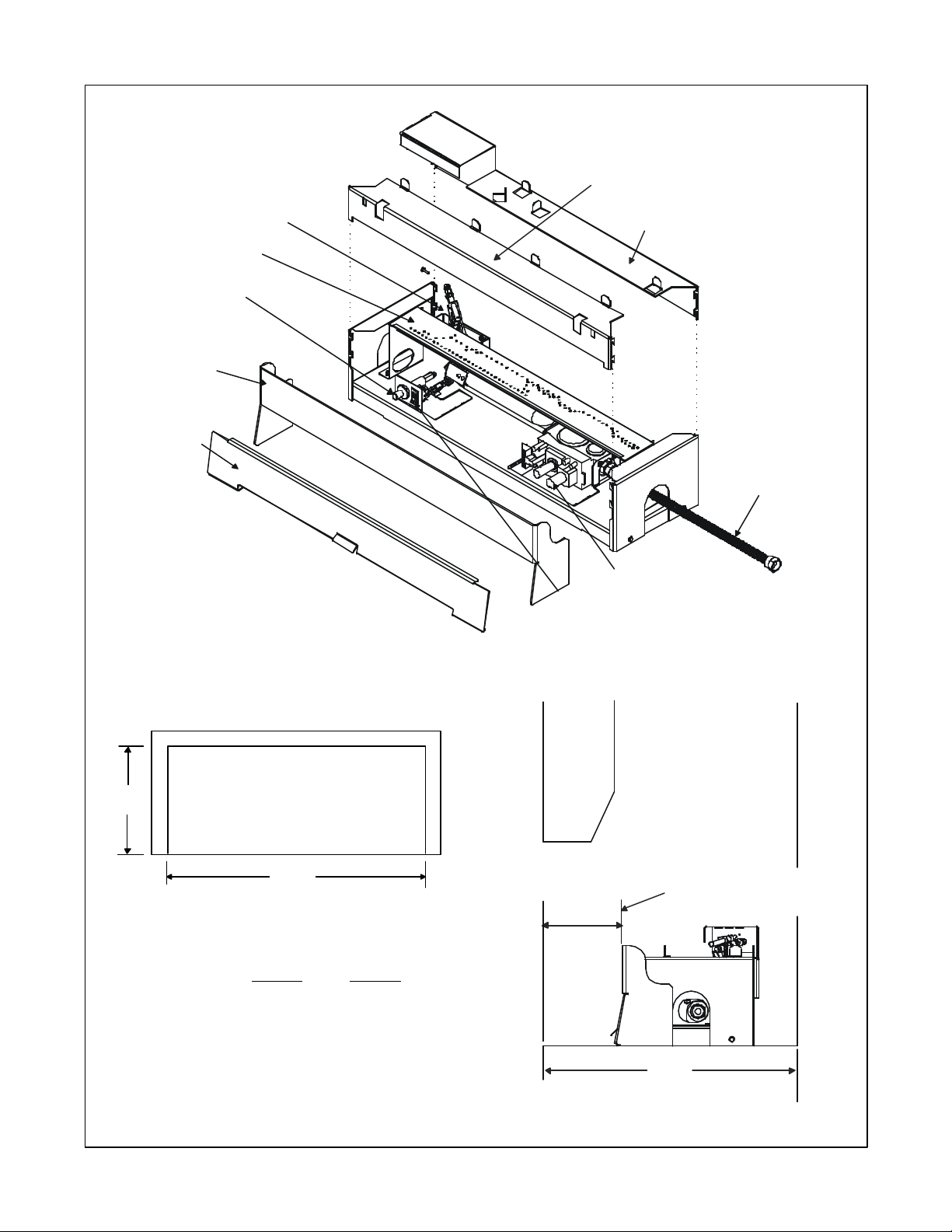
DEPTH
WIDTH
TOP VIEW - FIREPLACE AREA
GRATE
ON/OFF
FLEX TUBE
FRONT
SUROUND
SURROUND
NOTE: Unit must
be 33mm back from
fireplace front.
CONTROL
ACCESS
COVER
BURNER
PIEZO
IGNITOR
PILOT
ASSEMBLY
SWITCH
GAS
VALVE
REAR
FIREPLACE OPENING
WIDTH: 700mm 1050mm
DEPTH: 300mm 460mm
HEIGHT: 425mm 540mm
FIGURE 1
u
TOP VIEW
Minimum Maximum
33mm
MINIMUM
300mm
DEPTH
Page 5

5
1.0 INTRODUCTION
Model GRL-700-AU Gas Log Sets are Decorative Gas
Appliances for Installation in a Solid-Fuel Burning Fireplace. Minimum fireplace size for GRL-700-AU: height
425mm, width 700mm, depth 300mm.
This log set is to be installed only in a solid-fuel burning fireplace with a working flue and one constructed of
noncombustible material or into an approved Jetmaster
gas firebox. The minimum permanent vent opening provided by the fireplace chimney damper to vent the flue
products must not be less than 40,000mm2. The chimney damper MUST be fixed in a fully opened position
and the fireplace must have a proper draft.
WARNING: OPEN THE CHIMNEY DAMPER TO
!
ITS FULLY OPEN POSITION WHEN BURNING
THIS GAS LOG SET.
WARNING: LOGS MUST NEVER BE BURNED
!
WITHOUT THE FLUE DAMPER IN THE FULL
OPEN POSITION. FAILURE TO DO SO IS DANGEROUS TO YOUR HEALTH AND VOIDS ALL
WARRANTIES.
WARNING: ALL GAS APPLIANCES PRO-
!
DUCE SOME CARBON MONOXIDE WHEN
OPERATED. CARBON MONOXIDE IS A COLORLESS, ODORLESS, POISONOUS GAS. ADEQUATE PROVISIONS MUST BE MADE TO PROVIDE COMBUSTION AIR FOR THIS GAS LOG SET.
IF OUTSIDE AIR IS NOT INCLUDED IN THE FIREPLACE, IT MAY BE NECESSARY THAT AN ADDITIONAL COMBUSTION AIR SOURCE BE PROVIDED.
CAUTION: DO NOT PLACE ARTICLES ON OR
AGAINST THIS APPLIANCE.
CAUTION: DO NOT USE OR STORE FLAMMABLE
MATERIALS NEAR THIS APPLIANCE.
CAUTION: DO NOT SPRAY AEROSOLS IN THE VICINITY OF THIS APPLIANCE WHILE IT IS IN OPERA TION.
WARNING: THIS UNIT IS NOT FOR USE
!
WITH SOLID FUEL. SOLID FUELS SHALL
NOT BE BURNED IN A FIREPLACE WHERE A
DECORA TIVE APPLIANCE IS INSTALLED.
TO REDUCE THE RISK OF FIRE OR INJURY FROM
BURNS AND FOR THE PROTECTION OF YOUNG
CHILDREN OR THE INFIRM, A SECONDARY GUARD
IS RECOMMENDED.
2.0 ASSEMBLY
CAUTION: WHEN INSTALLING THIS LOG SET IN
A FACTORY BUILT FIREPLACE, BE CERTAIN TO
CONSULT THE FIREPLACE INSTALLATION
MANUAL. ALL KNOCKOUTS IN THE FIREPLACE
THROUGH WHICH THE GAS SUPPL Y LINE IS RUN
MUST BE RESEALED WITH INSULATION AFTER
THE GAS LINE IS IN PLACE.
Model GRL-700-AU contains complete gas-burner,
decorative front, and log components needed. Use caution when handling logs to avoid damage. Position gasburner assembly to the rear of the fireplace. Once fully
assembled slide access door into place.
WARNING: LOGS OTHER THAN THOSE
!
SUPPLIED WITH THIS UNIT MUST NOT BE
USED.
CAUTION: To minimize the possibility of spillage and
to maximize proper draft, position the log set as close
to the back of the fireplace as possible.
The installation, including provisions for combustion and
ventilation air, must conform with the AGA Gas Installation Code.
Do not use this appliance if any part has been under
water. Immediately call a qualified service technician
to inspect the unit and to replace any part of the control
system and any gas control which has been underwater.
Page 6
6
OPTIONAL WALL SWITCH,
A. Inlet gas supply pressure for purposes of input ad-
justment, shall be 6.0 inches w.c. (1.5kPa) for natural gas and 11 inches w.c. (2.75kPa) for propane.
Manifold (outlet) pressure should be 3.2 inches w.c.
(.80kPa) for natural gas and 9.6 inches w.c. (2.40kPa)
for propane models.
B. NOTE: THE GAS SUPPLY LINE SHOULD BE
PURGED OF ANY TRAPPED AIR PRIOR TO THE
FIRST FIRING OF THE UNIT.
C. CAUTION: During the initial purging and subse-
quent lightings, NEVER allow the gas control
valve knob to remain depressed in the "PILOT"
position without pushing the red ignitor button
at least once every second.
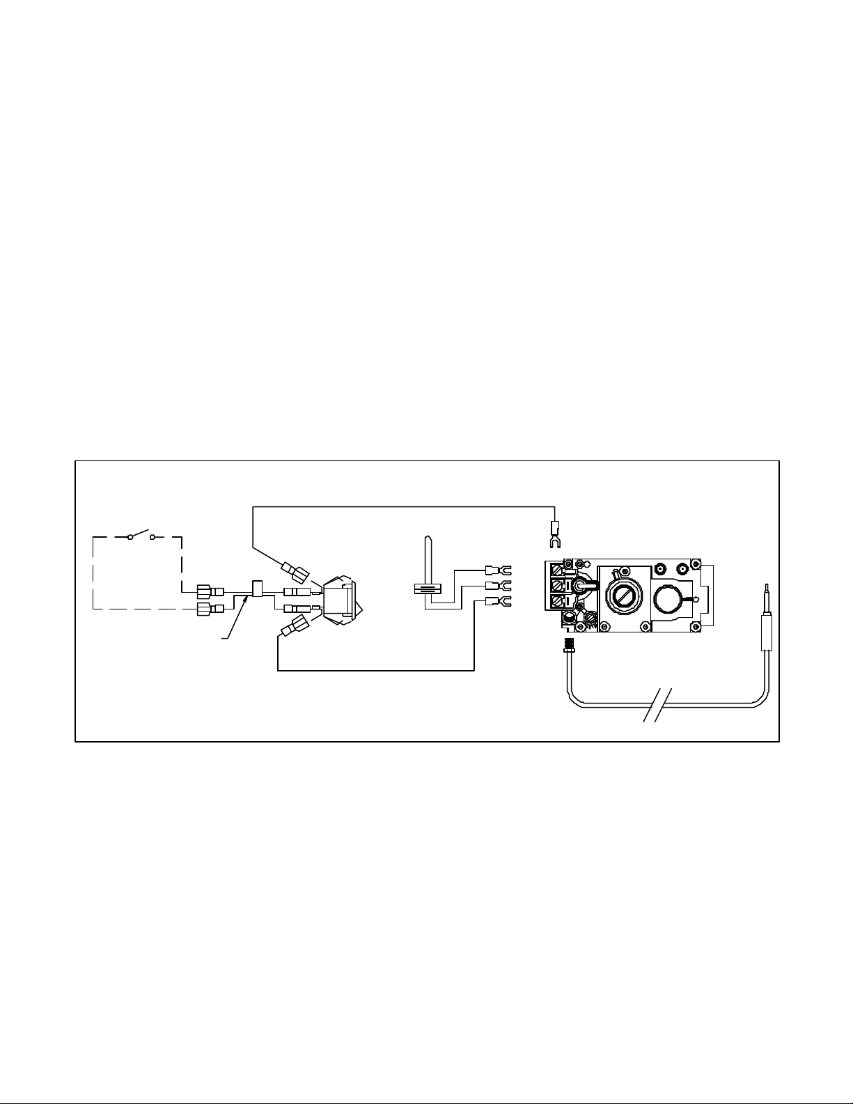
D. Your appliance control system is a millivolt type. It
consists of a pilot burner, a gas control valve/regulator, a thermopile, a piezo ignitor, and an ON/OFF
rocker switch. For control system wiring diagram
see Figure 2.
E. NOTE: An Optional Remote Control Kit and Wall
Switch Kit , for turning the burner ON/OFF are available. Detailed installation instructions are found in
each kit.
F. Test fire the unit after referring to the SAFETY IN-
FORMATION and LIGHTING INSTRUCTIONS
found in Section 3 in this manual, or on label plate
assembly found on the gas-burner.
G. Using a soap-solution or other device, check sys-
tem for leaks. Refer to Section 3, OPERATING
GUIDELINES and MAINTENANCE INSTRUCTIONS.
H. Once the gas-burner is test fired and gas supply
lines are purged, assembly of the grate and logs is
required.
NOTE: Appliances incorporating a live fuel effect may
exhibit slight carbon deposits.
THERMOSTAT OR REMOTE
REMOTE SWITCH
Figure 2
PIGTAIL
ON/OFF
SWITCH
OFF
ON
TP/TH
TP
TH
THERMOPILE
GAS VALVE
THERMOCOUPLE
Page 7

7
Log Set Assembly: GRL-700-AU-LOGS
ON/OFF
FLEX TUBE
FRONT
SUROUND
SURROUND
Model: GRL-700-AU
STEP 1: Attach grate to as-
sembly by sliding hooks into openings on the front surround.
LOG PLACEMENT
INSTRUCTIONS
u
STEP 2: Ensure that tabs on
front and rear surrounds are bent
as shown in Figure 1. Carefully
remove logs from carton and place
as shown.
PIEZO
IGNITOR
GRATE
CONTROL
ACCESS
COVER
Figure 1
ASSEMBLY
BURNER
PILOT
SWITCH
GAS
VALVE
REAR
1
2
5
6
3
4
CAUTION: Logs are fragile. Carefully remove the
logs from the packaging.
NOTE: Overhead view and front view of burner,
decorative front and surround.
Page 8

Heat-n-Glo GRL-700/GRL-850
Glowing Embers (Mineral Wool) Placement
Natural Gas
• Place single layer of 10mm circular sized pieces
next to burner ports, taking care not to place
material on or between ports.
• Do not use all of the ‘ember’ in the packet. One
packet should last 5-6 applications.
• Repeat application at the start of each season or
at the next fireplace service (annually).
Note: The contents of the bag is intended for multiple applications.
Do not use complete contents for the initial application. Save
remaining material for use at the next fireplace servicing. Keep
away from children. Do not eat.
Page 9

Heat-n-Glo GRL-700/GRL-850
Glowing Embers (Mineral Wool) Placement
LPG
• Place single layer of 10mm circular sized pieces
on top of burner ports.
• Increase the quantity of the “glowing embers” on
the right, centre and left hand side, as indicated, of
the burner where there is a cluster of burner ports.
• Do not use all of the ‘ember’ in the packet. One
packet should last 4-5 applications.
• Repeat application at the start of each season or
at the next fireplace service (annually).
Note: The contents of the bag is intended for multiple applications.
Do not use complete contents for the initial application. Save
remaining material for use at the next fireplace servicing. Keep
away from children. Do not eat.
Page 10

8
1
STEP 3: LOG #1 (SRV506-701)
Put log #1 behind the locating tab on the right rear corner and up against the locating tab in the center.
1
2
2
STEP 4: LOG #2 (SRV2010-703)
Place log #2 on the right front corner of the unit using its locating slots (on log bottom).
3
3
STEP 5: LOG #3 (SRV506-717)
Place log #3 against the left front corner of log #2 as shown.
Page 11

9
4
4
330mm
STEP 6: LOG #4 (SRV591-703)
Rest log #4 in between the locating tabs on the rear shelf and rest its front top 330mm from the left corner of
the decorative front.
5
5
STEP 7: LOG #5 (SRV550-714)
Rest log #5 against log #3 and rest its right edge on log #1.
6
STEP 8: LOG #6 (SRV530-716)
Place log #6 in the groove on top of log #2 with its front on log #1.
6
Page 12

10
3.0 OPERATING GUIDELINES AND
MAINTENANCE INSTRUCTIONS
Upon completing the gas line connection, a small
amount of air will be in the lines. When first lighting the
pilot light, it will take a few minutes for the lines to
purge themselves of this air. Once the purging is complete, the pilot and burner will light and operate as indicated in the instruction manual. Subsequent lighting of
the appliance will not require such purging.
WARNING: BE SURE FIREPLACE SCREEN
!
OR GLASS DOORS ARE IN PLACE WHEN
BURNING FIREPLACE LOGS. UNLESS OTHER
PROVISIONS FOR COMBUSTION AIR ARE PROVIDED, THE SCREEN OR DOORS SHALL HAVE
AN OPENING FOR INTRODUCTION OF COMBUSTION AIR. THIS GAS LOG SET IS NOT DESIGNED TO OPERATE WITH AIR TIGHT GLASS
DOORS. IF GAS ODOR IS NOTICEABLE, TURN
CONTROL KNOB TO "OFF" POSITION AND
CHECK ALL CONNECTIONS FOR LEAKS. DO
NOT USE OPEN FLAME. ADEQUATE COMBUSTION AND COOLING AIR MUST BE PROVIDED
OR THE UNIT WILL NOT FUNCTION PROPERL Y.
The following conditions must not cause spillage of
combustion products:
• cold chimney or flue system
• open or closed doors or windows
• operation of any exhaust or extraction fans
• operation of any other gas appliance in the room or
dwelling
Proper means must be employed to ensure sufficient
draft.
PILOT
FLAME
THERMOCOUPLE
Figure 3
The thermocouple should be engulfed in the pilot flame (see
Figure 3).
Periodically examine the area around the burner neck and
the pilot. Any dirt or lint in this area should be removed.
This will ensure long life and trouble free operation. When
the appliance is put back in service, check the burner flame
patterns.
The appliance and venting system should be inspected
before initial use and inspected and cleaned at least annually by an authorized field service person.
Note to Installer: Disconnect this appliance and advise
owner if any spillage or abnormal operation occurs which
can't be rechecked immediately.
To obtain proper operation, it is imperative that the pilot
and main burner flame characteristics are steady, not
lifting or floating.
Page 13

11
SAFETY INFORMATION
FOR YOUR SAFETY READ BEFORE LIGHTING
WARNING: IF YOU DO NOT FOLLOW THESE INSTRUCTIONS
!
EXACTLY, A FIRE OR EXPLOSION MAY RESULT CAUSING PROPERTY DAMAGE, PERSONAL INJURY, OR LOSS OF LIFE.
A. This appliance has a pilot which must be lighted
by hand. When lighting the pilot, follow these instructions exactly.
B. BEFORE LIGHTING smell all around the appli-
ance area for gas. Be sure to smell next to the
floor because some gas is heavier than air and will
settle on the floor.
WHAT TO DO IF YOU SMELL GAS:
• Do not try to light any appliance.
• Do not touch any electric switch; do not use any
phone in your building.
• Immediately call your gas supplier from a
neighbor’s phone. Follow the gas supplier’s instructions.
C. Use only your hand to push in or turn the gas
control knob. Never use tools. If the knob will
not push in or turn by hand, don’t try to repair it,
call a qualified service technician. Force or attempted repair may result in a fire or explosion.
D. Do not use this appliance if any part has been
under water. Immediately call a qualified service technician to inspect the appliance and to
replace any part of the control system and any
gas control which has been under water.
Page 14

12
LIGHTING INSTRUCTIONS
LIGHTING INSTRUCTIONS
1. "STOP!" Read the safety information on previous
page.
2. Remove the control access cover.
3. Turn the valve control knob to the "OFF" position.
To do this, you must turn the knob
clockwise to the "Pilot" position, and
then press in and continue turning
clockwise to the "OFF" position.
GAS CONTROL VALVE
NOTE: Knob cannot be turned from "PILOT" to
"OFF" unless knob is pushed in slightly. Do not
force.
4. WAIT FIVE (5) MINUTES TO CLEAR OUT ANY
GAS. Then smell for gas, including near the
floor. If you then smell gas, STOP! Follow "B"
in the safety information on the previous page.
If you don't smell gas, go to the next step.
5. The pilot should not require accessing for lighting
purposes. The pilot is located at the left end of
the burner.
PILOT ASSEMBLY
6. To put the control in the "Pilot" position, turn the
control knob counter-clockwise to the
"Pilot" position.
7. To light the pilot depress the control knob and then
depress the red piezo button until it makes a
clicking sound. It may be necessary to repeat this
step. If the pilot does not light after 10 seconds, go
back to step 3. The control knob should be held in
for a MINUTE after pilot ignition.
• If the control knob does not pop out when re-
leased, STOP-shut off the gas supply to the fire-
place control valve, and IMMEDIATELY call your
service technician or gas supplier.
• If the pilot will not stay lit after two tries, turn the
control knob to the "OFF" position and call your
service technician or gas supplier.
8. After the pilot has been lit, the burner can be turned
on by turning the knob counter-clockwise
to the "ON" position. Flip the ON/OFF
switch to the "ON" position.
9. Replace control access cover.
TO TURN OFF GAS APPLIANCE
1. Remove the control access cover.
2. Turn ON/OFF switch to "OFF".
3. Turn the valve control knob clockwise to
the "Pilot" position, then depress knob and
continue turning to "OFF" position.
4. Replace control access cover.
Page 15

13
Service Parts
GRL-700-AU
u
(NG, LP) Exploded Parts Diagram
8
4
1
3
Beginning Manufacturing Date: 4-2003
Ending Manufacturing Date: ________
2
11
5
7
6
9
10
12 Log set assembly
15
17
16
8
18
14
13
Part number list on following page.
Page 16

14
4.0 REPLACEMENT PARTS: GRL-700-AU
When requesting service or replacement parts for your decorative gas log set, please provide model
number and serial number. All parts listed in this manual may be ordered from an authorized dealer.
ITEM
1 ON/OFF Rocker Switch 060-521A
2 Burner NG 2010-003
2 Burner LP 2010-005
3 Burner Orifice NG 526-801
3 Burner Orifice LP 526-800
4 Piezo Ignitor 418-513
5 Valve NG 060-524
5 Valve LP 060-526
6 Access Door 2010-216
7 Flex Gas Supply Line 303-301
Description SERIAL # PART NUMBER
u
8 Surround Left and Right 2010-201
9 Surround Front 2010-200
10 Decorative Front 2010-217
11 Surround Rear 2010-203
12 Log Set Assembly LOGS-700-AU
13 Log 1 SRV506-701
14 Log 2 SRV2010-703
15 Log 3 SRV506-717
16 Log 4 SRV591-703
17 Log 5 SRV550-714
18 Log 6 SRV530-716
u
Pilot Assembly NG 506-510A
Pilot Assembly LP 596-511A
Page 17

15
LIMITED 10 YEAR WARRANTY
HEAT-N-GLO, a brand of Hearth & Home Technologies Inc.
In order to presumptively establish the dates to which your HEAT-N-GLO Limited Warranty runs, you must mail
the completed warranty card to HEAT-N-GLO, a brand of Hearth & Home Technologies Inc., 20802 Kensington
Boulevard, Lakeville, MN 55044, within 60 days of the date of the fireplace installation. If you fail to do so, you may
be required to prove the date of installation before warranty work can be performed.
The warranty exclusions and limitations of liability are effective upon installation of the fireplace.
Subject to the conditions set forth herein, HEAT-N-GLO, a brand of Hearth & Home Technologies Inc. (“HEAT-N-
GLO”) extends the following warranty with respect to HEAT-N-GLO, a brand of Hearth & Home Technologies Inc.
If HEAT-N-GLO is reasonably satisfied that any part or portion of the fireplace covered by this Limited Warranty
is defective in material or workmanship under normal use and service as described in the Operating Instructions,
HEAT-N-GLO will take the following actions:
1. If the defect is reported during the first year from the date of installation (stainless steel burners and fiber logs
are covered for 3 years), HEAT-N-GLO will replace or repair the defective components at its sole expense. The
decision whether to replace a component shall be made at HEAT-N-GLO’s sole discretion. This Limited
Warranty does not cover components broken during shipping, misuse or careless handling. HEAT-N-GLO
shall be not responsible for any indirect, incidental, or consequential damages or for any costs other than those
incurred by HEAT-N-GLO to repair or replace the defective component. If components (including venting) other
than factory approved components are used, all warranty and liability on the fireplace is voided. Defects
reported after the first year will not be covered by warranty unless they fall within the purview of
paragraph 2 or 3 below.
2. If the following defects are reported during the second year after the date of installation, HEAT-N-GLO will supply
replacement parts at the current wholesale price: defective electrical or manual components, optional
components or accessories, and glass panels (not including glass panels broken during misuse or careless
handling). HEAT-N-GLO shall not be responsible for any labor, transportation or other costs. Furthermore, it
shall not be liable for any indirect, incidental or consequential damages.
3. HEAT-N-GLO will replace or repair a defective firebox or heat exchanger, at any time during the 10 years from
the date of installation. The decision whether to replace the defective component shall be made at HEAT-NGLO’s sole discretion. HEAT-N-GLO shall not be responsible for any indirect, incidental or consequential
damages or for any costs other than those incurred by HEAT-N-GLO to repair or replace the defective
component.
This Limited Warranty is the exclusive remedy available to you. If HEAT-N-GLO cannot effectively resolve a
warranty problem in an expedient and cost-effective manner, it can discharge its entire warranty liability by
refunding the price of the product to you.
Products made by other manufacturers, whether sold with the fireplace or added thereafter, are NOT covered by
this Limited Warranty. The use of other unauthorized components will make this warranty null and void. This
Limited Warranty will also be void if the appliance is not installed by a qualified installer in accordance with the
Installation Instructions. Furthermore, the Limited Warranty will be void if the fireplace is not operated, at all times,
according to the Operating Instructions furnished with the fireplace. Any service work must be performed by
authorized service representatives.
EXCEPT TO THE EXTENT PROVIDED BY LAW, NO OTHER EXPRESS OR IMPLIED WARRANTIES,
INCLUDING WARRANTIES OF MERCHANTABILITY OR FITNESS FOR A PARTICULAR PURPOSE, SHALL
APPLY TO THE FIREPLACE PRODUCT. In States that do not allow limitations on how long an implied warranty
lasts, or do not allow exclusion of indirect damages, those limitations or exclusions may not apply to you. You
may also have additional rights not covered in this Limited Warranty.
HEAT-N-GLO reserves the right to make changes at any time, without notice, in design, material, specifications
and prices. It also reserves the right to discontinue styles and products.
 Loading...