

Hearth and Home Technologies GO24SP-REM-NG, GO35SP-REM-LP, GO35SP-REM-NG, GO30SP-NG, GO35-IPI-NG User Manual
...
TM
Installation
DO N
O
T
D
IS
CA
R
D
Instructions
Models:
GO24SP-NG or LP, GO30SP-NG or LP
GO24SP-REM-NG or LP, GO30SP-REM-NG or LP
GO35SP-REM-NG or LP,GO40SP-REM-ng or LP
GO24-IPI-NG or LP, GO30-IPI-NG or LP
GO35-IPI-NG or LP, GO40-IPI-NG or LP
Grand Oak Gas Log Sets
Check with your local building code agency before you begin installation to ensure compliance with local codes, including
the need for permits and follow-up inspections. If you encounter any problems regarding code approvals, or if you need
clarication of any of the instructions contained here, contact the Technical Services Dept., Hearth & Home Technologies
Inc., 20802 Kensington Blvd., Lakeville, MN 55044, www.hearthnhome.com.
Installation and service of this
appliance should be performed by
qualied personnel. Hearth & Home
Technologies suggests NFI certied
or factory-trained professionals,
o r t e ch n ic i an s
s u p e r v i s e d b y
an N FI c er ti f ie d
professional.
CAUTION
DO NOT DISCARD THIS MANUAL
•
• Im portan t operating
a n d m a i n t e n a n c e
instructions included.
WARNING
•
Rea d , understand
an d fo ll ow th es e
instructions for safe
i ns ta ll at io n a n d
operation.
Leave this manual with
party responsible for
use and operation.
WARNING
If the information in these instructions is not followed exactly, a
re may result causing property
damage, personal injury, or death.
• Do not store or use gasoline or other ammable vapors and liquids in the vicinity of
this or any other appliance.
• What to do if you smell gas:
- Do not try to light any appliance.
- Do not touch any electrical switch. Do not
use any phone in your building.
- Immediately call your gas supplier from
a neighbor’s phone. Follow the gas
supplier’s instructions.
- If you cannot reach your gas supplier, call
the re department.
• Installation and service must be performed
by a qualied installer, service agency, or
the gas supplier.
Note: An arrow () found in the text signies change in
content.
Hearth & Home Technologies • Grand Oak Gas Log Sets • 4004-299 Rev H • 05/08
HOT! DO NOT TOUCH.
SEVERE BURNS MAY RESULT.
CLOTHING IGNITION MAY RESULT.
Glass and other surfaces are hot during
operation and cool down.
• Keep children away.
• CAREFULLY SUPERVISE children in same room as
appliance.
• Alert chil d r e n and adults to haza r d s of high
temperatures.
• Do NOT operate with protective barriers removed.
• Keep cl o t h i n g , fu r n i t u r e , dr a p e r i e s and ot h er
combustibles away.
In the Commonwealth of Massachusetts:
• This appliance must be installed by a licensed plumber
or gas tter.
• The chimney ue damper, when used with gas logs, will
be welded open or completely removed.
• A CO detector shall be installed in the room where the
appliance is installed.
1
Read this manual before installing or operating this appliance.
Homeowner Reference Information
Model Name: Date purchased/installed:
Serial Number: Location on appliance:
Dealership purchased from: Dealer phone:
Notes:
We recommend that you record the following pertinent
information about your gas log set:
Please retain this owner’s manual for future reference.
Congratulations
Congratulations on selecting a Hearth & Home Technologies
gas log set—an elegant and clean alternative to burning
wood. The Hearth & Home Technologies gas log set you
have selected is designed to provide the utmost in safety,
reliability, and efciency.
As the owner of this new gas log set, you’ll want to read and
carefully follow all of the instructions contained in this owner’s
manual. Pay special attention to all cautions and warnings.
This owner’s manual should be retained for future reference.
We suggest you keep it with your other important documents
and product manuals.
The information contained in this owner’s manual, unless
noted otherwise, applies to all models and gas control
systems.
Your new gas log set will give you years of durable use and
trouble-free enjoyment. Welcome to the Hearth & Home
Technologies family of appliance products!
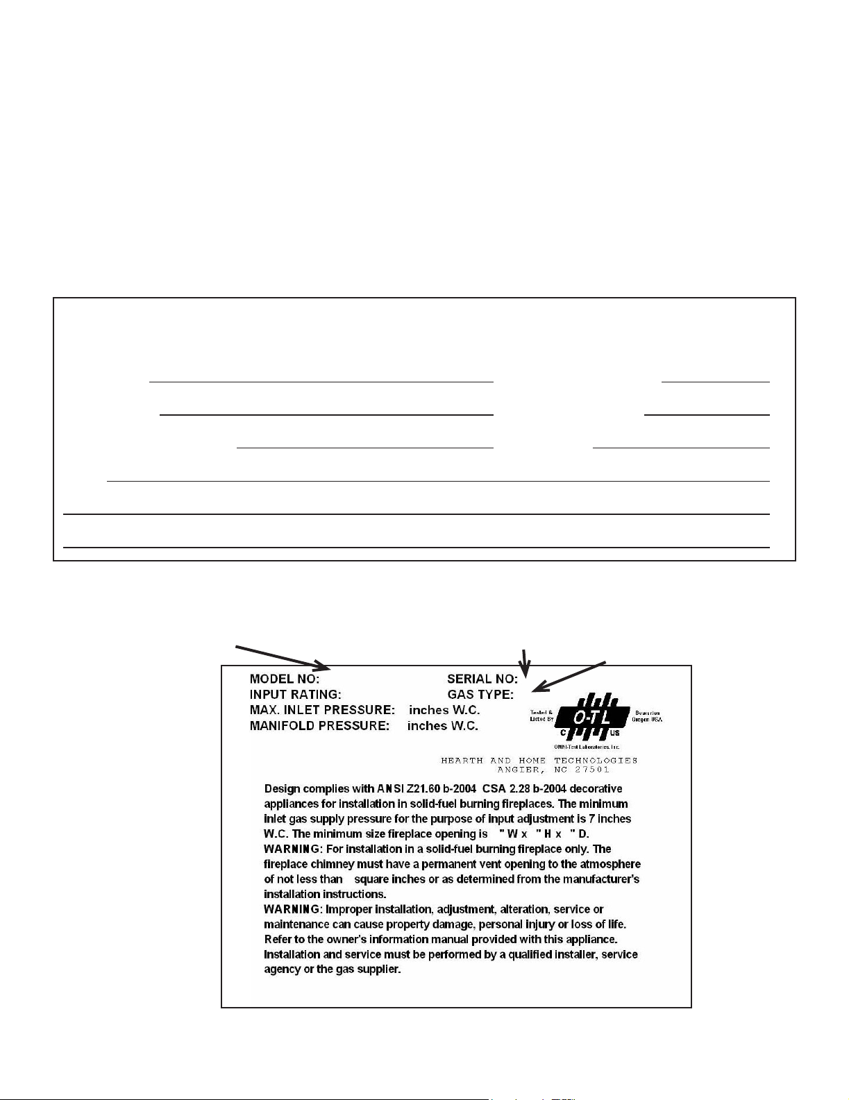
Listing Label Information/Location
The model information regarding your specic gas log set can be found on the rating plate.
Model #
Serial #
Gas Type
2
Hearth & Home Technologies • Grand Oak Gas Log Sets • 4004-299 Rev H • 05/08
WARNING
WARNING
Improper installation, adjustment, alteration, service
or maintenance can cause injury or property damage.
Refer to the owner’s information manual provided with
this appliance. For assistance or additional information
consult a qualied installer, service agency or the gas
supplier.
CAUTION
Sharp Edges
• We a r protective gloves
and safety glasses during
installation.
A. Design and Installation Considerations
The Gas Log Hearth Kit consists of the following:
• Log Set
• Burner/Pan Assembly
• Grate Assembly
• Rock Wool
• Sand (NG only)
• Lava Rock
• Damper Stop
• Vermiculite
• Platinum Embers
HOT! DO NOT TOUCH.
SEVERE BURNS MAY RESULT.
CLOTHING IGNITION MAY RESULT.
Glass and other surfaces are hot during
operation and cool down.
• Keep children away.
• CAREFULLY SUPERVISE children in same room as
appliance.
• Alert chil d r e n and adults to haza r d s of high
temperatures.
• Keep cl o t h i n g , fu r n i t u r e , dr a p e r i e s and ot h er
combustibles away.
- Review proper placement of logs, rockwool, lava rock
and vermiculite.
- Check the wiring.
- Ensure there are no gas leaks.
- Ensure the ow of combustion and ventilation air is not
obstructed (front grilles and vent caps).
• Before installing into a solid fuel burning replace, the
chimney and rebox should be inspected and cleaned to
remove soot, creosote, ashes, paint, bird nests etc.
• Annual examination of the chimney must be performed
by a qualied agency to ensure proper ventilation of ue
gases created by this appliance.
B. Tools and Supplies Needed
Tools and supplies normally required for installation:
Pliers
Phillips screwdriver
Tape measure
Crescent wrenches
Gas shutoff valve
Non-corrosive leak check solution
3/4 in. wrench, 7/16 in. wrench
C. Important!
• Do not remove any of the attached metal plates, which
contain important safety and operating information.
• Keep the appliance area clear and free of all combustible
materials, gasoline and other ammable vapors and
liquids.
• Any safety screen or guard removed during servicing must
be replaced before operation.
• A qualied service technician must perform installation
and repair. The appliance should be inspected and cleaned
annually by a qualied service technician. More frequent
cleaning may be required due to excessive lint, dust, pet
hair, etc. It is imperative that the control compartments,
burners and air passageways are unobstructed during
operation.
Hearth & Home Technologies • Grand Oak Gas Log Sets • 4004-299 Rev H • 05/08
WARNING
Fire Risk
Exhaust Fumes Risk
• Do NOT use this appliance as a “vent-
free” heater.
The ue must be permanently open according
to Tables 1 and 2.
• Have the chimney and adjacent structure inspected
and cleaned by qualied professionals. Hearth & Home
Technologies recommends that NFI or CSIA certied
professionals, or technicians under the direction of certied
professionals, conduct a minimum of an NFPA 211 Level 2
inspection of the chimney.
• Replace component parts of the chimney and replace as
specied by the professionals.
• Ensure all joints are properly engaged and the chimney
is properly secured.
• Do not allow fans to blow directly into the replace. Avoid
any drafts that alter burner ame pattern.
• Do not use a blower insert, heat exchanger insert or other
accessories not approved for use with this appliance.
3
• This appliance must have a screen in place while the
appliance is in operation and, unless other provisions for
combustion air are provided, the screen shall have an
opening for introduction of combustion air.
• Solid fuels shall not be burned in a replace where a
decorative appliance is installed.
• If glass doors are present, the glass doors must be fully
opened while appliance is in operation.
WARNING
WARNING
Fire Risk
Explosion Risk
Verify inlet pressures.
• Hi g h pr e ss ur e ma y cau s e ov e rf ir e
condition.
• Low pressure may cause explosion.
Install regulator upstream of valve if line
pressure is greater than 1/2 psig.
Do NOT use this appliance if any part has been under
water. Immediately call a qualied service technician
to inspect the appliance and to replace any part of the
control system and any gas control which has been
under water.
D. Appliance Certication
This appliance is design certied by Omni International under the ANSI Z21.60b-2004 or CSA 2.26b-2004, Decora-
tive Appliances for Installation in Solid-fuel Burning
Fireplaces. Installation and the provisions for combustion
and ventilation air must conform to the National Fuel Gas
Code, ANSI Z223.1/NFPA 54, or the CSA B149.1, Natural
Gas and Propane Installation Code.
E. Gas Supply Connection
A 3/8 in. ared tting has been installed on the gas valve
inlet at the factory. Ensure ttings are of the appropriate size
and type on the gas line connection. If the tubing has to be
cut to length be sure to use the proper cutting and aring
tool. Also, be careful not to crimp the tubing while bending. If
the tubing becomes crimped, do not use for installation.
Gas resistant pipe compound must be used on all threaded
male connections to ensure a tight seal.
F. Gas Pressure
Proper input pressures are required for optimum appliance
performance. Gas line sizing requirements need to be made
following NFPA51.
WARNING
Fire Risk
Explosion Risk
High pressure will damage valve.
• Disconnect gas supply piping BEFORE
pressure testing gas line at test pressures
above 1/2 psig.
• Close the manual shutoff valve BEFORE
pressure testing gas line at test pressures
equal to or less than 1/2 psig.
• Gas Supply Pressure: Minimum inlet gas supply pressure
must be 7.0 in. W.C. for natural gas or 11 in. W.C. for LP
gas for the purpose of input adjustment. Maximum inlet
gas pressure must not exceed 10.5 in. W.C. for natural
gas or 13 in. W.C. for LP gas. The gas line supplying the
appliance must be sufcient size to furnish the appropriate
supply pressure to the appliance while operating in the
“High” setting.
• Pressure tap screws must be closed before turning gas
on to the appliance.
• Gas Line Pressure Test: Perform pressure test according
to state and local code (if pressure exceeds 1/2 in. psi (3.5
kPa)) before appliance is connected. Be sure to release
air pressure from the gas line before connection is made
to the appliance. Excessive pressure will damage the gas
control and may cause a gas leak.
• Gas Leak Test: Make sure the gas connections are tight.
Turn on the gas and coat each joint with a non-corrosive
gas leak check solution. Air bubbles will form indicating
any leaks. DO NOT USE A FLAME OR ANY TYPE OF
IGNITION SOURCE TO CHECK FOR LEAKS. All leaks
must be corrected before proceeding with installation.
• The appliance must only be installed in a solid-fuel burning
replace with the ue damper clamped open according
to Tables 1 and 2. The replace must be constructed of
non-combustible material.
• The minimum permanent free opening (in square inches)
that must be provided by the replace chimney or damper
to vent the ue gases is provided in Tables 1 and 2. If the
free opening is smaller than the specied area, do not use
this appliance.
• The damper must be removed or xed in a manner in
which will secure it open. Some jurisdictions require the
damper to be removed or permanently welded fully open.
Check with state and local codes.
• Be sure that the chimney is completely unobstructed to
ensure proper ventilation of ue gases including carbon
monoxide (CO). CO (a poisonous gas) is tasteless,
odorless, colorless and undetectable without proper
equipment.
• Refer to Table 3 to determine minimum replace opening
requirements before proceeding.
4
Hearth & Home Technologies • Grand Oak Gas Log Sets • 4004-299 Rev H • 05/08
G. Negative Pressure
Negative pressure results from the imbalance of air avail-
able for the replace to operate properly. Causes for this
imbalance include:
• Exhaust fans (kitchen, bath, etc.).
• Range hoods.
• Combustion air requirements for furnaces, water heaters
and other combustion appliances.
• Clothes dryers.
• Loc a ti on o f r et u rn -a i r v en t s t o f ur n ac e or ai r
conditioning.
• Imbalances of the HVAC air handling system.
• Upper level air leaks: recessed lighting, attic hatch
opening, duct leaks.
Table 1 for Factory Built Fireplaces
Free Opening Area (in square inches) of Chimney Damper for Venting combustion
Products from Decorative Appliances for Installation in Solid Fuel Burning Fireplaces.
Chimney Ht.
(Feet)*
10 35.3 not approved 44.2 not approved
15 26.4 38.5 32.2 45.4
20 22.1 31.2 26.4 37.4
25 18.1 27.3 22.9 31.2
30 17.3 24.6 20.4 28.3
35 15.9 22.1 18.9 25.5
40 15.2 20.4 18.1 23.8
GO 24 & 35
LP Gas
GO 24 & 35
Natural Gas
Table 2 for Masonary Built Fireplaces
Asphyxiation Risk
This appliance produces carbon monoxide
(CO).
• The free opening areas (in square inches)
• User must make sure damper is locked
• The installer is responsible to ensure
Fire needs to draft properly fo r sa f e
operation.
GO 30 & 40
LP Gas
WARNING
of the chimney damper as shown in the
following tables must be met.
open.
proper ventilation of ue gases before
appliance is used.
GO 30 & 40
Natural Gas
Free Opening Area (in square inches) of Chimney Damper for Venting
combustion Products from Decorative Appliances for Installation in Solid Fuel
Chimney Ht.
(Feet)*
6 49.2 64 56.6 71.4
8 45.5 59.7 52.4 66.9
10 41.7 54.3 48.2 60.2
15 37.7 48.8 43.2 54.1
20 34.3 44.4 39.8 49.1
30 31.2 40.3 35.9 44.5
* Height is measured from the hearth to the top of the chimney.
Minimum height is 6 ft.
GO 24 & 35
LP Gas
Burning Fireplaces.
GO 24 & 35
Natural Gas
GO 30 & 40
LP Gas
GO 30 & 40
Natural Gas
Table 3 for Minimum Fireplace Dimensions
Log Set
GO24 32 in. 20 in. 18 in. 21 in. 73,000 61,000
GO30 38 in. 20 in. 18 in. 27 in. 80,000 70,000
GO35 34 in. 23 in. 22 in. 22 in. 88,000 80,000
GO40 40 in. 23 in. 22 in. 29 in. 92,000 82,000
Front
Opening Depth Height
Rear
Width
Natural
BTU
Propane
BTU
Hearth & Home Technologies • Grand Oak Gas Log Sets • 4004-299 Rev H • 05/08
5
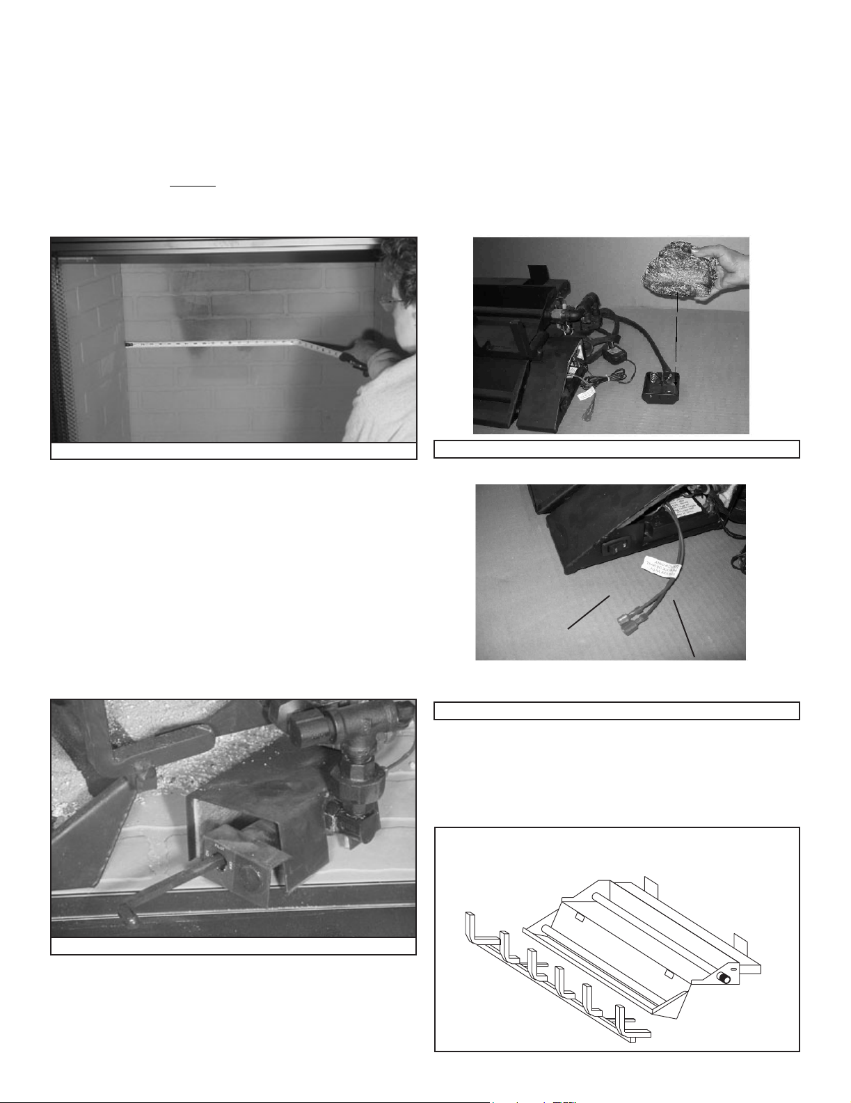
H. Inspect the Appliance and Components
• Remove the contents from the carton labeled “Burner”.
Attached to the burner are tags identifying the manufacturer
name, serial number, model number (including gas log
size), BTU ratings, gas type, etc.
• Review the attached tags before proceeding. Ensure
that all minimum replace dimension requirements are
achieved using Table 3 . See Figure 1. Ensure the gas
type provided in the replace coincide with the gas type
marked on the tag.
• IPI models include a battery box which holds 2 “D” size
batterys. The battery box should be placed in the right
front corner of your replace and covered with the log
cover as shown in Figure 3.
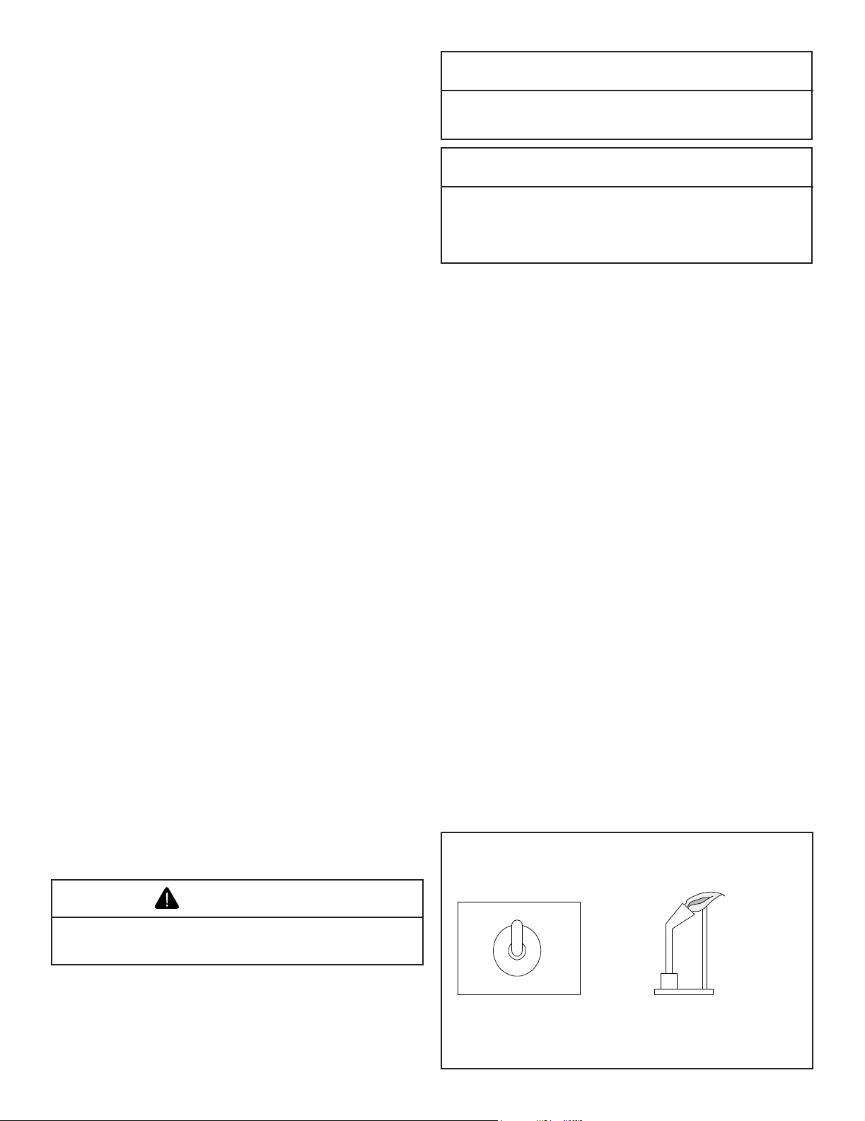
• An On/Off switch is provided as part of the assembly. It
is located on the front right side of the burner assembly
as shown in Figure 3A.
• Optional remote control system can be incorporated
with this system by connecting the remote system to the
connection wires shown in Figure 3A.
Battery Box Cover
Battery Box
Figure 1 Measure Firebox
• The burner is assembled with the controls installed at the
factory and is designed to connect one end of the 3/8 in.
supply line before placing inside the replace. Ensure the
connection is tightened using a 3/4 in. wrench.
• Place the burner towards the rear and center of the
replace and connect to the gas line. Follow instructions
in “F. Gas Pressure” to check for gas leaks.
• During shipping and handling of this appliance the safety
pilot control valve cover may not be in place. Once
the burner is installed in the replace, be sure to place
the cover over the valve to prevent overheating. See
Figure 2.
Figure 3 Battery Box and Cover (for IPI units only)
On/Off Switch
Optional Remote
Connection
Figure 3A Control Box for IPI
• Install the grate by placing the inserts (attached to the
grate) into the slots provided in the burner pan. Slide the
inserts into the slots (Figure 4) and push the grate as far
as possible to the locked position. GO 35 & GO 40 (not
shown) grate installs in the same manner.
• For propane (LP) installations skip to “J for Propane Gas
Installation”.
Figure 2 Valve Cover (Safety Pilot)
6
Hearth & Home Technologies • Grand Oak Gas Log Sets • 4004-299 Rev H • 05/08
Figure 4 Placing Grate
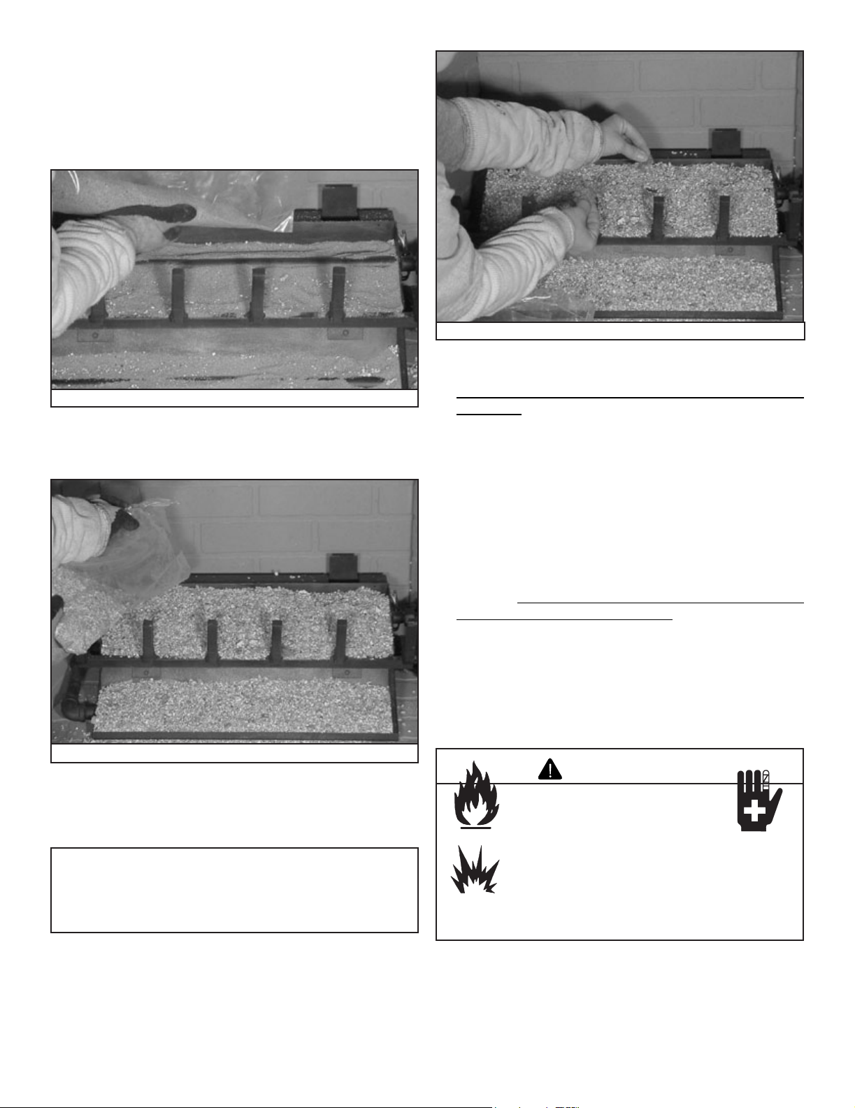
I. For Natural Gas Installation (for all units)
• Pour sand into the burner pans to the point where the
burner pipe is covered. See Figure 5. Level the sand
from right to left to ensure an even ame pattern. At this
point the pan should be half full. Be sure not to cover pilot
assembly.
Figure 7 Placing Rock Wool
Figure 5 Sand
• Pour vermiculite over the sand in the pans until they are
full. See Figure 6.
Figure 6 Placing Vermiculite
• Lightly place dime-size pieces of rock wool evenly on top
of the sand and vermiculite to achieve a glowing ember
effect. See Figure 7.
Note: For best results, do not pack down the rock wool.
The placement of rock wool can have an effect on ame
pattern and may need to be adjusted to achieve a desired
appearance.
• Inspect the pilot burner to ensure it is clear of any
rock wool.
• Remove the Platinum Bright Embers™ from the package.
For optimum performance peel each piece apart in layers
and lightly place on top of the vermiculite and rock wool
where the ame is blue. This will achieve the desired
realism.
• The gas burns at the point of the least resistance. In
case of an uneven ame pattern it may be necessary to
adjust the materials in the pans (using an object such as
a screwdriver) to achieve the desired effect.
• Place desired amount of lava granules on the oor of the
replace. DO NOT ALLOW THE GRANULES TO COME
IN CONTACT WITH THE FLAMES. (Lava granules may
contain moisture which, when heating, may cause it to pop
out during installation and set-up.) Ensure the controls
and switches are unobstructed after the granules are
installed.
• Place logs. See Sections S thru Y.
• Place accent logs around burner on oor of replace.
WARNING
Fire Risk
Explosion Risk
Personal Injury Risk
Failure to position the parts in accordance
with the diagrams provided with the log
pa ckages or fail ure to use onl y parts
approved with this appliance may result in
property damage or personal injury.
Hearth & Home Technologies • Grand Oak Gas Log Sets • 4004-299 Rev H • 05/08
7
Damper
Stop Clamp
Damper
J. For Propane Gas Installation (for all units).
WARNING
Fire Risk
Explosion Risk
Personal Injury Risk
An explosion could occur if a connection is
made directly to an unregulated propane
(LP) tank.
Pour vermiculite into each burner pan to the point where
each pan is completely full. Level the vermiculite from right
to left to ensure an even ame pattern. See Figure 6.
Note: Be sure to not cover the pilot assembly (located on
the right side of the burner pan, installed in the vertical
position) with vermiculite.
• Inspect the pilot burner to ensure it is clear of any
rock wool.
• Remove the Platinum Bright Embers™ from the package.
For optimum performance peel each piece apart in layers
and lightly place on top of the vermiculite and rock wool
where the ame is blue. This will achieve the desired
realism.
• The gas burns at the point of the least resistance. In
case of an uneven ame pattern it may be necessary to
adjust the materials in the pans (using an object such as
a screwdriver) to achieve the desired effect.
• Place desired amount of lava granules on the oor of the
replace. DO NOT ALLOW THE GRANULES TO COME
IN CONTACT WITH THE FLAMES. (Lava granules may
contain moisture which, when heating, may cause it to pop
out during installation and set-up.) Ensure that the controls
and switches are unobstructed after the granules are
installed. DO NOT COVER THE AIR MIXER LOCATED
ON THE LOWER LEFT SIDE OF THE BURNER.
• Place logs as shown in Sections S thru Z.
• Place accent logs around burner on oor of replace.
WARNING
Fire Risk
Explosion Risk
Personal Injury Risk
Pour vermiculite into each burner pan (LP) to
the point where each pan is completely full.
Failure to do so may cause the lighting to be
delayed and this can be dangerous..
• Lightly place dime size pieces of rock wool evenly on top
of the vermiculite to achieve a glowing ember effect. See
Figure 7.
Note: For best results, do not pack down the rock wool.
The placement of rock wool can have an effect on ame
pattern and may need to be adjusted to achieve a desired
appearance.
Note: The state of Massachusetts requires that the
chimney ue damper, when used with gas logs, be welded
open or completely removed. In the Commonwealth of
Massachusetts this appliance must be installed by a
licensed plumber or gastter.
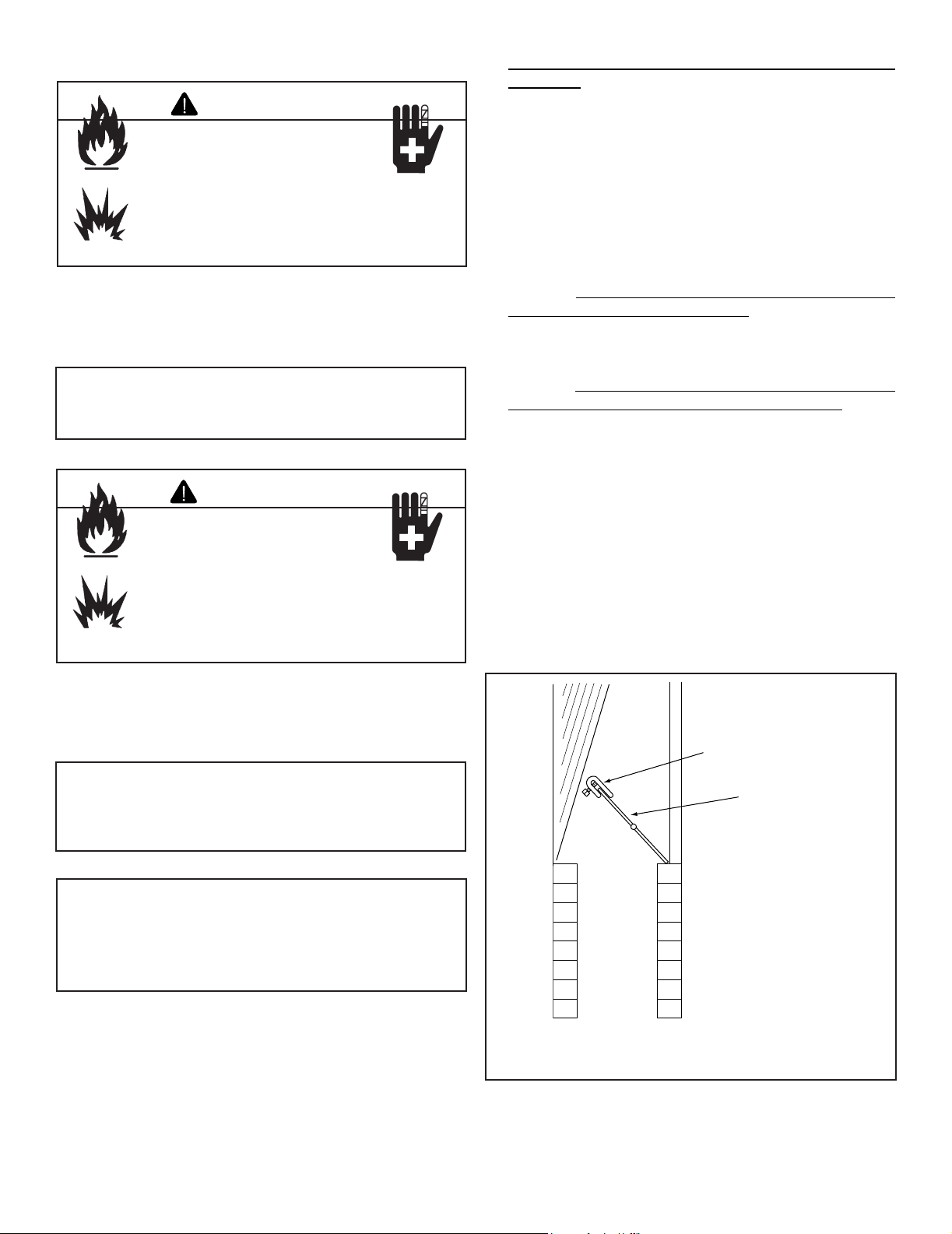
K. Damper Stop Installation Instructions
Included in the burner assembly box is a damper stop clamp
which attaches to the damper as shown (Figure 8). Install
the clamp to the damper ensuring that the minimum requirements (Tables 1 and 2) are achieved. Use a 7/16 in. wrench
to secure the clamp to the damper. If the damper clamp pro-
vided does not t your application, other means of securing
the proper opening must be provided by the installer.
Figure 8 Damper Stop Clamp
8
Hearth & Home Technologies • Grand Oak Gas Log Sets • 4004-299 Rev H • 05/08
L. Inspect the Venting System
PILOT
ON
OFF
Pilot
Thermocouple
The replace venting system is designed and constructed to
develop a positive ow adequate to remove ue gases to the
outside atmosphere. See replace installation instructions.
A spillage test must be made before the installed
appliance is left with the consumer.
• Close all doors and windows in the home.
• Light the log set (see Lighting Instructions).
• After three minutes, test with a smoke match, smoke
candle, stick incense or cigarette 1 in. below the top of
the opening (lintel) moving across the full width. If spillage
(smoke down into the room) occurs, it will most likely be
near the top, outside corners.
Possible cures if spilling occurs:
• The damper needs to be opened further.
• The replace opening needs to be reduced by adding a
drop panel across the top under the lintel.
• The air supply from outdoors needs to be increased. Open
the outside air kit if the appliance is so equipped, or crack
open a door or window.
• If necessary, seek expert advice. Do not operate this
appliance.
Cleaning
• Periodic examination and cleaning of the venting system
of the replace should be done before initial use and at
least annually by a qualied agency.
M. Cleaning and Maintenance Instructions
Always remember:
• Do not place an y combust i ble mater ial near th e
appliance.
• Do not place any paper, trash or other material on the log
set or in the replace.
• Do not touch any part of the appliance when it is in
operation.
• Do not operate this appliance without the replace screen
closed.
Your appliance is designed to be virtually maintenance free,
although periodic visual inspection and cleaning is required.
Follow the instructions below for the correct procedures. An
annual examination and cleaning the venting system by a
qualied person is also recommended.
CAUTION
After burning, the logs become fragile. Take care in
handling.
CAUTION
Before cleaning the appliance, be sure it is turned
completely off. The pilot should also be turned off. The
unit must be completely cooled.
Do not allow soot to build up on the logs
Your logs require little care. Keep the burner assembly, logs
and burner area surrounding the logs clean by brushing with
a dry paint brush at least twice a year.
• Always turn off the gas to the pilot before cleaning.
For relighting, refer to Section P Thru R. Lighting
Instructions.
• Always keep the appliance clean and free from combustible
materials, gasoline and other ammable vapors and
liquids.
• Never obstruct the ow of combustion and ventilation air.
Keep the front of the appliance clear of all obstacles and
materials.
• Leave clearance of at least 36 in. from the front of the
replace.
N. Safety Valve Pilot Flame Adjustment Instructions
The pilot ame adjustment screw is located on the front
side of the pilot gas tubing port. Using a small straight blade
screwdriver, turn the screw clockwise to adjust the pilot
ame down and counterclockwise to adjust the ame up.
This screw is sensitive; therefore it will not take much adjust-
ment to accomplish this ame adjustment.
CAUTION
• Logs can get very hot. Handle only when they are
cool.
Hearth & Home Technologies • Grand Oak Gas Log Sets • 4004-299 Rev H • 05/08
9

O. Fequently Asked Questions
Can I close the glass doors on my replace when using my gas logs?
No. The gas log sets are designed for use in replaces with all replace doors fully opened. Operating your log set with the doors closed will
cause overheating, premature failure of valve systems, and will void the warranty of your log set.
What sort of maintenance do gas logs require?
Vented gas logs do not require regular maintenance. However, it is a good idea to have valves, pilots and gas connections on your set
periodically inspected by a hearth professional. Although it is not required maintenance, annually refurbishing the ember material and periodic
cleaning of the logs will help maintain your set’s beauty and realism.
Why do I need a safety pilot control for my LP gas log set?
Since LP gas is heavier than air, it tends to gather or pool in low spots, rather than dissipating through the chimney ue. Furthermore, escaping
LP gas can go unnoticed until a signicant quantity has gathered, creating a potential hazard. Installation of a safety pilot control ensures that gas
cannot accidentally pass through the burner when not operating, eliminating the risk of such an occurrence.
Does the ember material burn-up, and do I need to replace it periodically?
The ember material is a reproof, organic mineral material called rock wool, and does not burn or require periodic replacement; however, annual
refurbishment of the embers will help maintain the beauty and realism of your log set.
Can I burn real wood along with my gas logs?
No. The intense heat of a wood re will damage your logs, burners, grates and valves, and will void your warranty.
Will gas logs help my chimney that drafts poorly?
No. Improper or poor draft will not be helped by gas logs. Please have your chimney inspected by a hearth professional or chimney sweep in
order to determine how to correct the problem.
Can I close my replace damper to get more heat from my vented gas log set?
No. Vented gas logs are designed to be operated with the damper in the fully opened position. This gas log set produces carbon monoxide gas.
The damper must be removed or clamped fully open using the “C” clamp provided with the set.
My gas logs make a whistling noise when I burn them. What causes this?
This behavior is normally caused by using a corrugated ex connector to hook up the gas log set. We recommend the installer use the supplied
aluminum connector rather than the corrugated exible type.
Can I move or change the position of the logs on my gas log set?
Omni certied log sets should not be altered - log placement must be exactly as indicated in the set’s installation instructions.
Can I install my gas log set myself?
No. We recommend installation be performed by an NFI certied hearth professional, HVAC professional, gas tter, or plumber experienced
in gas log installation. Most localities require installation of any gas appliance to be performed by a professional. Please check with your local
inspection agency/department.
What are the gas logs made of?
The gas logs are made of a mixture of pre-red, expanded clay and a special high-temperature cement, with a wire mesh reinforcement. This
combination creates a strong, ceramic material capable of withstanding extreme temperatures, yet also allows molding of the intricate detail
found in these gas log sets.
I have a vented log set, and the logs have black soot on them. Is this normal?
Soot build-up on vented gas logs is a normal part of the combustion process. Natural gas log sets generally produce less soot than liquid propane
log sets. We recommend any soot build up be removed periodically using a product designed for gas log soot removal.
Can I add a remote control to my log set after it has been installed?
You can easily add a remote to the gas log set if it is already equipped with a solenoid type valve or an IPI ignition system. In addition, vented
sets without solenoid valves can also be converted to remote operation by adding, in the eld, a solenoid type valve; however, a hearth
professional must do this type of in-the-eld modication.
Do I have to re-light the pilot light every time I use my log set?
No. You can light the pilot in the fall and leave it on throughout the winter, as the pilot is extremely clean burning and uses very little gas
(approximately 1,500 BTU/hr.). The log set is equipped with a safety shut off device that will automatically shut the gas off if the pilot ame is
extinguished.
Is the gas log set approved by a testing agency?
Yes. The GO series has been design certied by Omni under the ANSI Z21.60-2004 Decorative Appliances for Installation in Solid Fuel
Burning Fireplaces. The installation and the provisions for combustion and ventilation air must conform to the National Fuel Gas Code, ANSI
Z223.1/NFPA 54. Check with your local inspections department for further information.
10
Hearth & Home Technologies • Grand Oak Gas Log Sets • 4004-299 Rev H • 05/08

TO TURN OFF GAS TO APPLIANCE
LIGHTING INSTRUCTIONS
A. This appliance has a pilot that must be lighted by hand. When lighting the pilot, follow these instructions exactly.
B. BEFORE LIGHTING smell all around the appliance area for gas. Be sure to smell next to the floor because some
gas is heavier than air and will settle on the floor.
WHAT TO DO IF YOU SMELL GAS
• Do not try to light any appliance.
• Do not touch any electrical switch; do not use any phone in your building.
• Immediately call your gas supplier from a neighbor’s phone. Follow the gas supplier’s instructions.
• If you cannot reach your gas supplier, call the fire department.
C. Use only your hand to push in or turn the gas control handle. Never use tools. If the handle will not push in or turn
by hand, do not try to repair it. Call a qualified service technician. Force or attempted repair may result in fire or
explosion.
D. Do not use this appliance if any part has been under water. Immediately call a qualified service technician to inspect
the appliance and to replace any part of the control system and any gas control that has been under water.
1. STOP! Read the safety information previously listed above.
2. Turn gas control handle clockwise to the “OFF” position.
3. Wait 5 minutes to clear out any gas. Then smell for gas, including near the floor. If you smell gas, STOP! Follow “B”
in the safety information above on this label. If you don’t smell gas, go to the next step.
4. Locate pilot (mounted on the right side of the top burner pan).
5. Turn control handle counterclockwise to the “PILOT” position.
6. Place a lit match at the pilot burner, and simultaneously push in on the control handle. This should ignite the pilot.
7. Once the pilot lights, continue to depress the control handle for 1 minute.
8. After 1 minute, slowly release control handle and it will pop back out. Pilot should remain lit. If it goes out, repeat
Steps 1 through 7.
• If the handle does not pop out when released, stop and immediately call your service technician or gas supplier.
• If the pilot will not stay lit after several tries, turn the gas control handle to “OFF” and call your service technician
or gas supplier.
9. Turn gas control handle counterclockwise to “ON”.
Turn gas control handle clockwise to “OFF” position. Do not force.
FOR YOUR SAFETY READ BEFORE LIGHTING
FOR YOUR SAFETY READ BEFORE LIGHTING
WARNING! IF THESE INSTRUCTIONS ARE NOT FOLLOWED EXACTLY, A FIRE OR EXPLOSION MAY RESULT
CAUSING PROPERTY DAMAGE, PERSONAL INJURY OR LOSS OF LIFE.
Control Knob
(Shown in “Pilot” Position)
Switch
Pilot Burner Assembly
Thermocouple
Solenoid
F
U
L
L
O
N
O
N
-
O
F
F
pilot
P. Lighting Instructions
• Remote Ready Valve (REM)
Hearth & Home Technologies • Grand Oak Gas Log Sets • 4004-299 Rev H • 05/08
11

Q. Lighting Instructions
• Safety Pilot Valve (STANDING PILOT VALVE)
FOR YOUR SAFETY READ BEFORE LIGHTING
WARNING: IF THESE INSTRUCTIONS ARE NOT FOLLOWED EXACTLY, A FIRE OR
EXPLOSION MAY RESULT CAUSING PROPERTY DAMAGE, PERSONAL INJURY OR
LOSS OF LIFE.
A. This appliance has a pilot that must be lighted by hand. When lighting the pilot, follow these
instructions exactly.
B. BEFORE LIGHTING smell all around the appliance area for gas. Be sure to smell next to the oor
because some gas is heavier than air and will settle on the oor.
WHAT TO DO IF YOU SMELL GAS
Do not try to light any appliance.
Do not touch any electrical switch: do not use any phone in your building.
Immediately call your gas supplier from a neighbor’s phone. Follow gas supplier’s
instructions.
If you cannot reach your gas supplier, call the re department.
C. Use only your hand to push in or turn the gas control handle. Never use tools. If the
handle will not push in or turn by hand, do not try to repair it. Call a qualied service
technician. Force or attempted repair may result in re or explosion.
D. Do no use this appliance if any part has been under water. Immediately call a qualied service
technician to inspect the appliance and to replace any part of the control system and any part of
the gas control that has been under water.
LIGHTING INSTRUCTIONS
1. STOP! Read the safety information listed above.
2. Turn gas control handle clockwise to the “OFF” position.
3. Wait 5 minutes to clear out any gas. Then smell for gas, including near the oor. If you smell
gas, STOP!. Follow “B” in the safety information above. If you do not smell gas go on to next step.
4. Locate pilot (mounted on the right side of the top burner pan).
5. Turn control handle counterclockwise to the “PILOT” position.
6. Place a lit match at the pilot burner and simultaneously push in on the control handle.
This should ignite the pilot.
7. Once the pilot lights, continue to depress the control handle for 1 minute.
8. After 1 minute slowly release control handle and it will pop back out. Pilot should remain lit.
If it goes out, repeat steps 1 through 7.
If the handle does not pop out when released, stop immediately and call your
service technician or gas supplier.
If the pilot will not stay lit after serveral tries, turn the gas control handle to the “OFF”
position and call your service technician or gas supplier.
9. Turn gas control handle counterclockwise to the “ON” position.
TO TURN GAS OFF TO APPLIANCE
Turn gas control handle clockwise to the “OFF” position. Do not force.
12
Hearth & Home Technologies • Grand Oak Gas Log Sets • 4004-299 Rev H • 05/08

R. Lighting Instructions
• IPI Pilot Valve (IPI)
Hearth & Home Technologies • Grand Oak Gas Log Sets • 4004-299 Rev H • 05/08
13

S. GO24 Grand Oak Series Logs
• Open the log box and remove the paper packaging and logs.
• Inspect each log for breakage that may have occurred during shipping and handling.
SRV738
SRV736 SRV738
SRV737
SRV722
SRV723
SRV724
SRV728
SRV729
14
SRV727
Hearth & Home Technologies • Grand Oak Gas Log Sets • 4004-299 Rev H • 05/08
SRV749
SRV743

Step 1
Step 2
Step 3
SRV737
SRV738
SRV736
SRV722
SRV723
SRV729
SRV724
SRV743
SRV728
SRV742
SRV727 not shown. See page 12, Step 3 for placement of log.
T. GO24 Grand Oak Series Log Placement Instructions
• Place logs EXACTLY as the following photos depict.
WARNING
Fire Risk
Explosion Risk
Personal Injury Risk
Failure to position the parts in accordance with these diagrams or failure to use only parts specically approved with this
appliance may result in property damage or personal injury.
Hearth & Home Technologies • Grand Oak Gas Log Sets • 4004-299 Rev H • 05/08
15

U. GO30 Grand Oak Series Logs Open the log box and remove the paper packaging and logs.
• Inspect each log for breakage that may have occurred during shipping and handling.
SRV720
SRV726
SRV722
SRV721A
SRV724
SRV721B
SRV723
SRV728
SRV742
SRV740
SRV743
16
SRV727
Hearth & Home Technologies • Grand Oak Gas Log Sets • 4004-299 Rev H • 05/08

V. GO30 Grand Oak Series Log Placement Instructions
Step 1
Step 2
Step 3
SRV721B
SRV720
SRV721A
SRV722
SRV723
SRV740
SRV743
SRV728
SRV742
SRV722
SRV724
SRV727
SRV726
• Place logs EXACTLY as the following photos depict.
Hearth & Home Technologies • Grand Oak Gas Log Sets • 4004-299 Rev H • 05/08
17

W. GO35 Grand Oak Series Logs
• Open the log box and remove the paper packaging and logs.
• Inspect each log for breakage that may have occurred during shipping and handling.
SRV816
SRV708
SRV709
SRV737
SRV728
SRV716
SRV808
SRV724
18
SRV707
SRV702
Hearth & Home Technologies • Grand Oak Gas Log Sets • 4004-299 Rev H • 05/08
SRV706

X. GO35 Grand Oak Series Log Placement Instructions
• Place logs EXACTLY as the following photos depict.
SRV737
SRV708
SRV709
SRV728
SRV716
SRV816
SRV707
Hearth & Home Technologies • Grand Oak Gas Log Sets • 4004-299 Rev H • 05/08
SRV808
SRV724
SRV702
SRV706
19

Y. GO40 Grand Oak Series Logs
• Open the log box and remove the paper packaging and logs.
• Inspect each log for breakage that may have occurred during shipping and handling.
SRV816
SRV700
SRV721A
SRV701
SRV721B
SRV728
SRV703
SRV808
SRV724
20
SRV707
SRV702
Hearth & Home Technologies • Grand Oak Gas Log Sets • 4004-299 Rev H • 05/08
SRV706

Z. GO40 Grand Oak Series Log Placement Instructions
• Place logs EXACTLY as the following photos depict.
SRV721A
SRV700
SRV816
SRV721B
SRV701
SRV728
SRV703
SRV808
SRV707
Hearth & Home Technologies • Grand Oak Gas Log Sets • 4004-299 Rev H • 05/08
SRV724
SRV702
SRV706
21

Replacement Parts
TM
7
8
9
14
15
16
10
Service Parts
Exploded Parts Diagram Beginning Manufacturing Date: N/A
GO Gas Logs Ending Manufacturing Date: Active
SP Valve Assembly
GO24 & 30
Grand Oak Gas Logs
IPI Valve Assembly
GO24,30,35,40
IPI Valve Assembly
22
Hearth & Home Technologies • Grand Oak Gas Log Sets • 4004-299 Rev H • 05/08

TM
Replacement Parts Con’t
Service Parts
Exploded Parts Diagram Beginning Manufacturing Date: N/A
GO Gas Logs Ending Manufacturing Date: Active
REM Valve Assembly
GO24,30,35 & 40
Grand Oak Gas Logs
28
2A
30
13
12
7
10
11
9
8
1
29
Hearth & Home Technologies • Grand Oak Gas Log Sets • 4004-299 Rev H • 05/08
23

TM
Service Parts
Service Parts List Beginning Manufacturing Date: N/A
GO Gas Logs Ending Manufacturing Date: Active
Grand Oak Gas Logs
# Description of Part 24 in. 30 in. Qty.
1 Grate Assembly GR-300-24 GR-300-30 1
2 Burner Pan Assembly BPA-300-24 BPA-300-30 1
2A Burner Pan Assembly GO35 & GO40 BPA-300-35 BPA-300-40 1
3 Connector FT-1-24 FT-1-30 1
4 Bottom Burner Orice NG BPO-2-40 BPO-2-38 1
4 Bottom Burner Orice LP AM-2-54 AM-2-52 1
5 Top Burner Orice NG BPO-2-26 BPO-2-26 1
5 Top Burner Orice LP AM-2-44 AM-2-43 1
6 Pilot Booster (LP only) MT300-IC MT300-IC 1
7 Valve Cover MT300-VC MT300-VC 1
8 Pilot Assy NG (SP only) 07-1008-NG 07-1008-NG 1
8 Pilot Assy LP 07-1008-LP 07-1008-LP 1
9 Pilot Heat Pad 10-1041 10-1041 1
10 Regulator NG (4.0) 08-1031 08-1031 1
10 Regulator LP (10.0) 08-1030 08-1030 1
11 Valve (REM units only) 11-2267 11-2267 1
12 Valve Knob (REM units only) 11-2268 11-2268 1
13 Log Switch (REM units only) Switch Log Switch Log 1
14 Valve SP 07-1025 07-1025 1
15 SP Handle Tube Assy 11-2110 11-2110 1
16 SP Handle Assy 14-1019 14-1019 1
17 Top Burner Orice NG (24” & 30”IPI Unit Only) BPO-2-26 BPO-2-26 1
17 Top Burner Orice LP (24” & 30”IPI Unit Only) AM-2-49 AM-2 49 1
18 Bottom Burner Orice NG (24” & 30”IPI Unit Only) BPO-2-50 BPO-2-50 1
18 Bottom Burner Orice LP (24” & 30”IPI Unit Only) AM-2-54 AM-2-54 1
19 Switch (IPI Unit Only) 01-1069 01-1069 1
20 Pilot NG (IPI Unit Only) 2090-012 2090-012 1
20 Pilot LP (IPI Unit Only) 2090-013 2090-013 1
21 Control Module (IPI Unit Only) 593-592 593-592 1
22 Battery Holder (IPI Unit Only) 593-594A 593-594A 1
23 Valve NG (IPI Unit Only) 593-500 593-500 1
23 Valve LP (IPI Unit Only) 593-501 593-501 1
24 Valve Bracket (IPI Unit Only) MT-350-VC MT-350-VC 1
25 Control Box (IPI Unit Only) MT-350-CBA MT-350-CBA 1
26 Pilot Bracket (IPI Unit Only) MT-350-PB MT-350-PB 1
27 Wire Harness (IPI Unit Only) 593-590A 593-590A 1
28 Top Burner Orice NG (GO35” & 40” units only) BPO-2-24 BPO-2-10 1
28 Top Burner Orice LP (GO35” & 40” units only) AM-2-51 AM-2-51 1
29 Middle Burner Orice NG (GO35” & 40” units only) BPO-2-28 BPO-2-16 1
29 Middle Burner Orice LP (GO35” & 40” units only) AM-2-47 AM-2-47 1
30 Bottom Burner Orice NG (GO35” & 40” units only) BPO-2-42 BPO-2-20 1
30 Bottom Burner Orice LP (GO35” & 40” units only) AM-2-52 AM-2-56 1
24
Hearth & Home Technologies • Grand Oak Gas Log Sets • 4004-299 Rev H • 05/08

TM
Service Parts
Service Parts List Beginning Manufacturing Date: N/A
GO Gas Logs Ending Manufacturing Date: Active
# Description of Part 24 in. 30 in. Qty.
Battery Cover Log (IPI units only) (not shown) 568A 568A 1
Sand (NG only) 4004-108 4004-108 2
Vermiculite 4004-109 4004-109 2
Lava Rock 4004-110 4004-110 2
Rock Wool 4004-111 4004-111 2
Damper Stop Assy 14354 14354 1
Platinum Bright Embers PBE-5 PBE-5 1
Grand Oak Gas Logs
Hearth & Home Technologies • Grand Oak Gas Log Sets • 4004-299 Rev H • 05/08
25

TM
Warranty
DECORATIVE GAS LOG LIMITED WARRANTY
Hearth & Home Technologies Inc. (HHT) extends the following warranty for decorative gas log sets as described herein, while it is in its loca-
tion or original installation. Dealers and employees of HHT have no authority to make any warranty or authorize any remedies in addition to or
inconsistent with the terms of this Program. This warranty gives you specic legal rights. You may also have other rights which vary from state
to state.
LIMITED WARRANTY. This decorative gas log set is comprised of a gas burner assembly with safety pilot valve and ceramic logs that are
manufactured by HHT. This Limited Warranty does not cover any part of the woodburning replace system in which this decorative gas appli-
ance must be installed. This decorative gas log set is warranted to be free of defects in material and workmanship for a period of ve (5) years
from the date of installation. This Limited Warranty extends only to decorative gas log sets installed in the United States or Canada.
EXCLUSIONS AND QUALIFICATIONS. This Limited Warranty is subject to the following exclusions and qualications: (1) This Limited War-
ranty does not apply to, and HHT assumes no responsibility for, any damages that result due to the installation or operation of this decorative
gas log set not in accordance with both the installation instructions and operating instructions furnished. (2) The decorative gas log set must be
subjected to normal use as explained in the operating instructions and the listing agency identication label attached to the burner pan assembly. This decorative gas log set is only intended to burn the fuel specied on the listing agency identication label. Use of any other fuel other
than specied on the listing agency identication label can create a life threatening situation and will void this limited warranty. (3) This Limited
Warranty applies only if the decorative gas log system has been installed in a vented replace that is suitable for burning wood. Adequate ventilation must be provided to allow proper drafting of the replace chimney system. HHT assumes no responsibility for improper performance of
the decorative gas log set caused by inadequate draft due to environmental conditions (e.g. wind currents, downdrafts), tight-sealing construction of the structure, or mechanical devices (e.g. air handling devices that include forced air furnaces and air conditioning units, exhaust fans
and ventilating devices), any and all of which may cause a negative pressure within the structure where the decorative gas log set is installed.
(4) This Limited Warranty applies only to the components of the Appliance manufactured by HHT. HHT expressly excludes from this Limited
Warranty any liability hereunder for defects or damage caused by the installation or use of any parts, devices or components that are not manufactured by HHT. (5) Labor costs to be paid by HHT pursuant to this Limited Warranty must be approved in advance of the performance of the
work by HHT and must not exceed the retail price of the replacement part. (6) This Limited Warranty will be voided if the decorative gas log
set is at any time removed or has been removed from the location in which it was originally installed. (7) Since building code requirements vary
greatly throughout the United States and Canada, users of this decorative gas log set should determine in advance whether there are any building code restrictions on the installation and use of this product. HHT makes no representation or warranty regarding building code compliance
and shall not be responsible for compliance therewith.
THERE ARE NO IMPLIED WARRANTIES OF MERCHANTABILITY OR FITNESS FOR PARTICULAR PURPOSE LIMITATION OF LIABILITY.
IT IS EXPRESSLY AGREED AND UNDERSTOOD THAT HHT’S OBLIGATION AND PURCHASERS EXCLUSIVE REMEDY UNDER THIS
LIMITED WARRANTY, UNDER ANY OTHER WARRANTY, EXPRESSED OR IMPLIED (INCLUDING MERCHANTABILITY AND FITNESS FOR
PARTICULAR PURPOSE), OR OTHERWISE, SHALL BE LIMITED TO THE REPLACEMENT OR REPAIR Of ONLY HHT BRAND COMPONENTS AND OPTIONAL COMPONENTS AS SPECIFIED ABOVE. THE DURATION OF ANY IMPLIED WARRANTY INCLUDING MERCHANTABILITY AND FITNESS FOR PARTICULAR PURPOSE APPLICABLE TO THIS GAS APPLIANCE IS LIMITED TO THE DURATION OF THE
FOREGOING WARRANTY. SOME STATES DO NOT ALLOW LIMITATIONS ON HOW LONG AN IMPLIED WARRANTY LASTS SO THE
ABOVE WARRANTY MAY NOT APPLY TO YOU. IN NO EVENT SHALL HHT BE RESPONSIBLE FOR ANY INCIDENTAL OR CONSEQUEN-
TIAL DAMAGES CAUSED BY DEFECTS IN THE DECORATIVE GAS LOG SET, WHETHER SUCH DAMAGE OCCURS OR IS DISCOVERED
BEFORE OR AFTER REPLACEMENT OR REPAIR, AND WHETHER SUCH DAMAGE IS CAUSED BY HHT NEGLIGENCE. SOME STATES
DO NOT ALLOW THE EXCLUSION OR LIMITATION OF INCIDENTAL OR CONSEQUENTIAL DAMAGES, SO THE ABOVE LIMITATION OR
EXCLUSION MAY NOT APPLY TO YOU.
HOW TO OBTAIN SERVICE. To obtain service under this Program, you must:
1. Send written notice of the claimed condition to the Technical Service Department, Hearth & Home Technologies Inc., 1915
West Saunders Street, Mt. Pleasant, Iowa 52641.
2. Provide proof of purchase to HHT.
3. Provide HHT reasonable opportunity to investigate the claim, including reasonable opportunity to inspect the Fireplace prior
to any repaid or replacement work and before the Fireplace has been removed from the place of original installation.
4. Obtain HHT’s consent to any warranty work before the work is done.
ADDITIONAL INFORMATION. If you would like information on current Hearth & Home Technologies products or want to locate a dealer in
your area, visit www.hearthnhome.com.
26
2003 Hearth & Home Technologies Inc.
Hearth & Home Technologies • Grand Oak Gas Log Sets • 4004-299 Rev H • 05/08

Contact Information
DO
NOT
DIS
C
AR
D
TM
Please contact your Hearth & Home Technologies dealer with any questions or concerns.
For the number of your nearest Hearth & Home Technologies dealer, please call 1-800-927-6841 or 1-888-427-3973.
- NOTES -
CAUTION
DO NOT DISCARD THIS MANUAL
•
•
• Im porta nt operating
a n d m a i n t e n a n c e
instructions included.
This product may be covered by one or more of the following patents: (United States) 4593510, 4686807, 4766876, 4793322,
4811534, 5000162, 5016609, 5076254, 5113843, 5191877, 5218953, 5263471, 5328356, 5341794, 5347983, 5429495,
5452708, 5542407, 5601073, 5613487, 5647340, 5688568, 5762062, 5775408, 5890485, 5931661, 5941237, 5947112,
5996575, 6006743, 6019099, 6048195, 6053165, 6145502, 6170481, 6237588, 6296474, 6374822, 6413079, 6439226,
6484712, 6543698, 6550687, 6601579, 6672860, 6688302B2, 6715724B2, 6729551, 6736133, 6748940, 6748942,
6769426, 6774802, 6796302, 6840261, 6848441, 6863064, 6866205, 6869278, 6875012, 6880275, 6908039, 6919884,
D320652, D445174, D462436; (Canada) 1297749, 2195264, 2225408, 2313972; (Australia) 780250, 780403, 1418504 or
other U.S. and foreign patents pending.
Rea d , understa n d
an d fo ll ow th e se
instructions for safe
i ns ta ll at io n an d
operation.
Hearth & Home Technologies • Grand Oak Gas Log Sets • 4004-299 Rev H • 05/08
Leave this manual with
party responsible for
use and operation.
27
 Loading...