

Page 1
INSTALLATION & OPERATING
INSTRUCTIONS
NOVUS SERIES
B-VENT GAS APPLIANCE
GNBC30, 33, & 36
WARNING: If the information in this manual
is not followed exactly, a fire or explosion may
result causing property damage, personal injury or loss of life.
Do not store or use gasoline or other flammable
vapors and liquids in the vicinity of this or any other
appliance.
What to do if you smell gas
Do not try to light any appliance.
Do not touch any electrical switch; do not use
any phone in your building.
Immediately call your gas supplier from a
neighbors phone. Follow the gas suppliers
instructions.
If you cannot reach your gas supplier, call the fire
department.
Installation and service must be performed by a
qualified installer, service agency or the gas
CAUTION:
Do not expose appliance to the elements (such as rain, etc.).
WARNING!
Improper installation, adjustment, alteration, service or maintenance can cause injury or property damage. Refer to this
manual. For assistance or additional information, consult a qualified installer, service agency or the gas supplier.
12-02 1 34615 Rev G
Page 2
NOVUS B-VENT INSTALLATION INSTRUCTIONS
TABLE OF CONTENTS
Design and Installation Considerations for B-Vents ...................................................................................................... 3
A. Applicance Specifications ............................................................................................................................................ 4
B. Location and Clearances .............................................................................................................................................. 5
C. Framing ......................................................................................................................................................................... 6
D. Setting the Appliance .................................................................................................................................................... 7
E. Venting........................................................................................................................................................................... 7
F. Utilities .......................................................................................................................................................................... 11
G. Finishing ...................................................................................................................................................................... 14
H. Appliance Preparation ................................................................................................................................................ 14
I. Determining the Ignition Type ..................................................................................................................................... 15
J. Lighting Instructions .................................................................................................................................................... 16
K. Seasonal Checklist ...................................................................................................................................................... 18
L. Start-up Issues ............................................................................................................................................................ 19
M. Maintenance Instructions ............................................................................................................................................ 20
N. Optional Components ................................................................................................................................................. 22
O. Replacement Parts ...................................................................................................................................................... 25
Index ............................................................................................................................................................................ 27
Warranty ...................................................................................................................................................................... 28
WARNING!
DO NOT use this appliance if any part has been under water. Immediately call a qualified service technician to
inspect the appliance and to replace any part of the control system and any gas control which has been under
water.
SAFETY PRECAUTIONS
1. Please read these installation instructions
completely before beginning installation
procedures. Failure to follow them could cause an
appliance malfunction resulting in serious injury
and/or property damage.
2. Always check your local building codes prior to
installation. This installation must comply with all
local, regional, state and national codes and
regulations.
3. Installation and repair should be done by a qualified
service person. This appliance should also be
inspected annually by a qualified service person.
More frequent inspections/cleaning may be
required due to excessive lint from carpeting,
bedding materials, etc. It is imperative that the
control compartment, burners and circulating air
passageways of the appliance be kept clean.
4. This is a vented decorative gas appliance. Do not
burn wood or other material in this appliance.
5. NEVER leave children unattended when there is a
fire burning in the appliance.
6. This appliance may only use the approved venting
systems shown in these installation instructions.
Venting
servicing a solid fuel burning appliance or a gas
fuel burning appliance.
must not be connected to chimney flue
7. NEVER use gasoline, gasoline-type lantern fuel,
kerosene, charcoal lighter fluid, or similar liquids
in this appliance. Keep any flammable liquids a safe
distance from the appliance.
8. While servicing this appliance, always shut off all
electricity and gas to the appliance. This will
prevent possible electrical shock or burns. Also,
make sure the appliance is completely cooled
before servicing.
9. Do not use this appliance if any part has been under
water. Immediately call a qualified service
technician to inspect the appliance and to replace
any part of the control system and any gas control
which has been under water.
10. Be sure to provide adequate clearances around the
air openings into the combustion chamber and
adequate accessibility clearances for servicing and
proper operation.
34615 Rev G 2 12-02
Page 3
NOVUS B-VENT INSTALLATION INSTRUCTIONS
DESIGN AND INSTALLATION CONSIDERATIONS FOR B-VENTS
When selecting a location for your B-Vent appliance, it is important to evaluate a number of considerations. Modern
construction techniques can create conditions that may not allow your vent to draft properly. This may result in spillage
from your B-Vent appliance, as well as cause other combustion appliances to operate incorrectly.
Tightly sealed construction is important for energy efficiency. Unfortunately, a great deal of effort has been directed to
tightening up sidewall construction, while considerably less attention has been paid to tightening upper portions of the
warm air envelope (insulated ceilings). This has increased the Stack Effect, a condition that increases the negative
pressure generated by the structure. This negative pressure will directly affect the drafting performance of a B-Vent
appliance vent. To minimize the negative pressure generated by stack effect, make certain that all ductwork installed in
the attic spaces is sealed airtight. Minimize the number of recessed light fixtures installed in the insulated ceiling and use
sealed recessed light fixtures. Finally, make certain the whole house fans and attic access panels are tightly sealed.
These are important design considerations that must be observed during the design and construction stage of the home.
If you desire to put an appliance in your basement, we recommend that you consider a direct vent gas appliance. Basements
always have a significant negative air pressure that causes the B-Vent system to be more susceptible to spillage and cold
flue backdrafting. Since direct vent gas appliances are sealed, they are not affected by the negative pressure that exists
in basements.
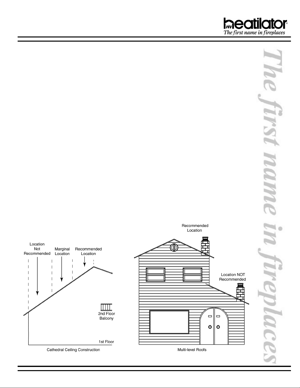
Finally, a B-Vent appliance performs best when the vent (roof termination) is located on the upper half of the roof, especially
when cathedral ceilings are present. Vents that are located on the lower half of the roof realize what is known as lazy flue
and will not draft as well as a vent that is located in the upper portion of the roof. The reason for this is that the stack effect
generated by the overall height of the living spaces inside the house will exceed the draft generated by the vent system.
If you desire to place an appliance in a location where the termination cap would be located on the lower half of a roof;
such as on an outside wall at the base of a cathedral ceiling, we recommend that you consider using a direct vent gas
appliance. This will ensure an appliance that operates correctly.
These properties do not affect just your B-Vent appliance. They can cause any woodburning fireplace as well as any
conventionally vented (B-Vent) gas appliance to operate improperly. Careful planning at this stage of your project will
ensure satisfaction with the operation of your appliance once it is completed.
12-02 3 34615 Rev G
Page 4
NOVUS B-VENT INSTALLATION INSTRUCTIONS
A. APPLICANCE SPECIFICATIONS
1. U.S. AND CANADA CERTIFICATION
The Novus B-Vent Gas Appliance has been tested in
accordance with the ANSI standard Z21.88-2000. In
Canada, the current CSA 2.33-2000, IR41, P4, and IR55
and have been LISTED by Underwriters Laboratories
Inc. for installation as described in this manual. All
components are UL, AGA, CGA or CSA safety certified.
2. LOCAL CODES
This installation must conform with local codes. In the
absence of local codes comply with the National Fuel
Gas Code ANSI Z223.1-latest edition in the U.S.A., and
the CAN/CGA B149, Installation Codes in Canada.
For assistance during installation contact your local
dealer or contact Heatilator Technical Services
Department, Hearth & Home Technologies, 1915 W.
Saunders Street, Mt. Pleasant, Iowa 52641, 1-800-843-
2848.
HEATILATOR® and NOVUS® are registered trademarks
of Hearth & Home Technologies
3. GLASS SPECIFICATIONS/CERTIFICATIONS
Heatilator gas appliances manufactured with tempered
glass may be installed in hazardous locations such as
bathtub enclosures as defined by the CPSC. The
tempered glass has been tested and certified to the
requirements of ANSI Z97.1-1984 and CPSC 16 CFR
1202. (Safety Glazing Certification Council SGCC# 1595
and 1597. Architectural Testing, Inc. Reports 02-
31919.01 and 02-31917.01.)
This statement is in compliance with SPCS 16 CFR
Section 1201.5 Certification and labeling requirements
which refers to 15 USC 2063 stating Such certificate
shall accompany the product or shall otherwise be
furnished to any distributor or retailer to whom the
product is delivered.
Some local building codes require the use of tempered
glass with permanent marking in such locations. Glass
meeting this requirement is available from the factory.
Please contact your dealer or distributor to order.
Tools and building supplies normally required for
installation:
Tools: Building Supplies:
Saw Wall-finishing materials
Pliers Framing material
Hammer Surround
Phillips screwdriver Caulking material
Tape measure
Plumb line
Level
Electric drill/bits
Square
Gloves
TYPICAL VERTICAL INSTALLATION
We strongly recommend that you DO NOT install B-
Note: Minimum and maximum clearances must be main-
tained at all times. Illustrations throughout these instructions reflect typical installations and are for design purposes
only. Actual installation may vary slightly due to individual
design preferences.
The illustrations and diagrams used throughout these installation instructions are not drawn to scale.
34615 Rev G 4 12-02
Vent Gas Appliances in strong negative air locations,
such as a basement or a public facility. Living rooms
with cathedral ceilings could be susceptible to a
negative air situation, but such installations can be
overcome through raising the termination, depending on specific installations. This appliance uses
room air for normal operation and could have problems establishing a positive draft in a negative air
location. In lieu, we recommend a Direct Vent Gas
Appliance.
Page 5
NOVUS B-VENT INSTALLATION INSTRUCTIONS
NOVUS NOMENCLATURE
rebmuNgolataCnoitpircseD
EL63CBNGrebmuNedoCredrOecnailppA
NGSUVONsaG
BtneV-B
CgnitalucriC
63ecnailppA"63-63
ecnailppA"33-33
ecnailppA"03-03
ELsaGlarutaN,toliPgnidnatS-xiffusoN
saGenaporP,toliPgnidnatS-L
saGlarutaN,toliPtnettimretnI-E
BEL63CBNG rebmuNedoCedargpUhtiwrebmuNedoCredrOecnailppA
BxoberiFkcalB
FedargpUtiKnaF
BEL63CBNG ELPMAXE ,saGenaporP,"63,gnitalucriCtaeH,tneV-B,SUVONsaG-
tnenopmoCnoitallatsnInoitpircseD
41KA )deilppuston-dednemmocerylhgih(tikriaedistuO
saGenaporP,toliPtnettimretnI-EL
xoberiFkcalBhtiwecnailppAtoliPtnettimretnI
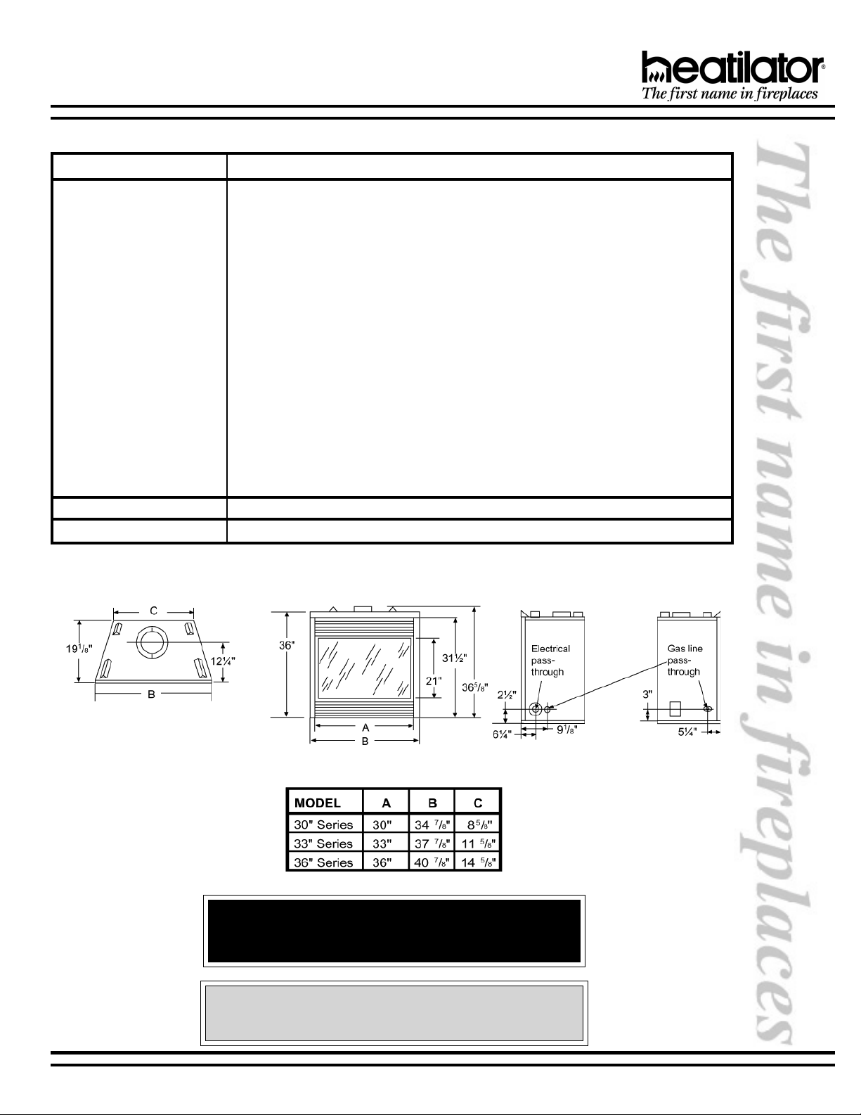
B. LOCATION AND CLEARANCES
Appliance Dimensions
WARNING!
Due to high temperatures, the appliance should be located
out of traffic and away from furniture and draperies.
CAUTION:
Do not expose appliance to the elements (such as rain, etc.).
12-02 5 34615 Rev G
Page 6
NOVUS B-VENT INSTALLATION INSTRUCTIONS
CAUTION:
Wear gloves and safety glasses for protection.
WARNING!
To prevent contact with sagging or loose insulation,
the appliance must not be installed against vapor
barriers or exposed insulation.
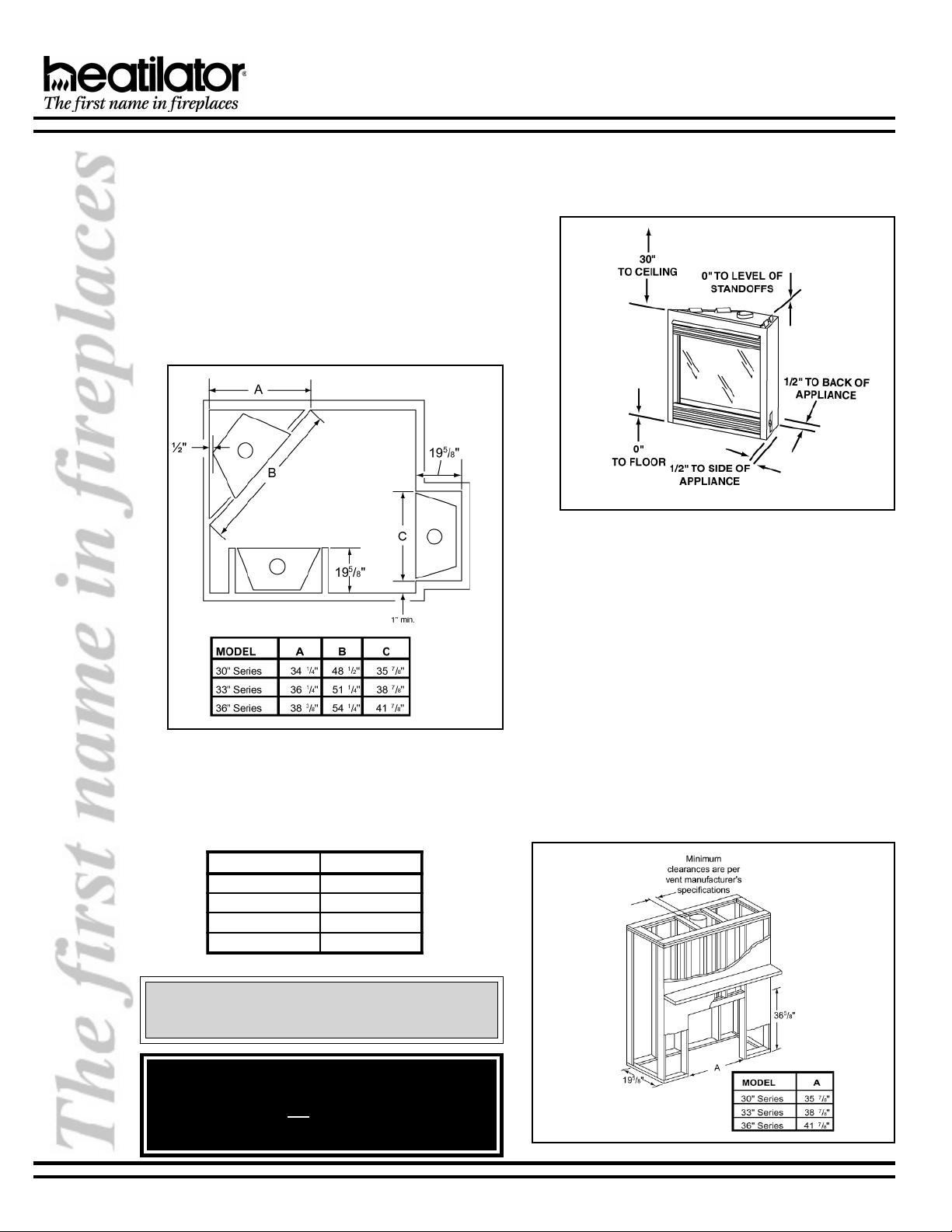
1. APPLIANCE LOCATIONS AND SPACE
REQUIREMENTS
Figure 1 illustrates a variety of ways the appliance may
be located in a room. The NOVUS Series may be
installed directly on the floor or raised on a hearth. These
appliances are certified for installation in a bedroom, bed/
sitting rooms or bathrooms in the U.S. and Canada,
provided that the bedroom or bathroom has a volume
of at least 1350 cubic feet.
Common venting of this gas appliance with other gas
appliances is not allowed in multifamily dwellings.
2. CLEARANCES
Figure 2 shows all clearances that must be maintained
around the appliance.
Figure 2
Appliance Clearances to Combustible Materials
Figure 1 - Appliance Locations
C. FRAMING
Figure 3 shows a typical framing of this appliance using combustible materials. All required clearances to combustibles must
be adhered to. Mantel height is measured from the base of the appliance.
noitcejorPletnaMthgieHletnaM
"21ot"9"14
"9ot"6"93
"6ot"3"83
"3ot0"63
34615 Rev G 6 12-02
Figure 3 - Framing
Page 7
NOVUS B-VENT INSTALLATION INSTRUCTIONS
CAUTION:
Provide adequate clearances around the air openings into the combustion chamber and adequate accessibility clearances for servicing and proper operation.
D. SETTING THE APPLIANCE
This appliance may be placed on a smooth combustible or noncombustible, continuous flat surface. When the appliance
is installed directly on carpeting, tile or other combustible material other than wood flooring, the appliance shall be installed
on a metal or wood panel extending the full width and depth of the appliance. Slide the appliance into position and level
the appliance from side-to-side and front-to-back. Shim with noncombustible materials as necessary.
Secure the appliance by bending out the nailing flanges on each side of the appliance and nail to framing. The nailing
flanges have been positioned 5/8 inch back from the front of the appliance to allow the addition of drywall.
WARNING!
To prevent contact with sagging or loose insulation, the appliance must not be installed against vapor
barriers or exposed insulation. Localized overheating could occur and a fire could result.
E. VENTING
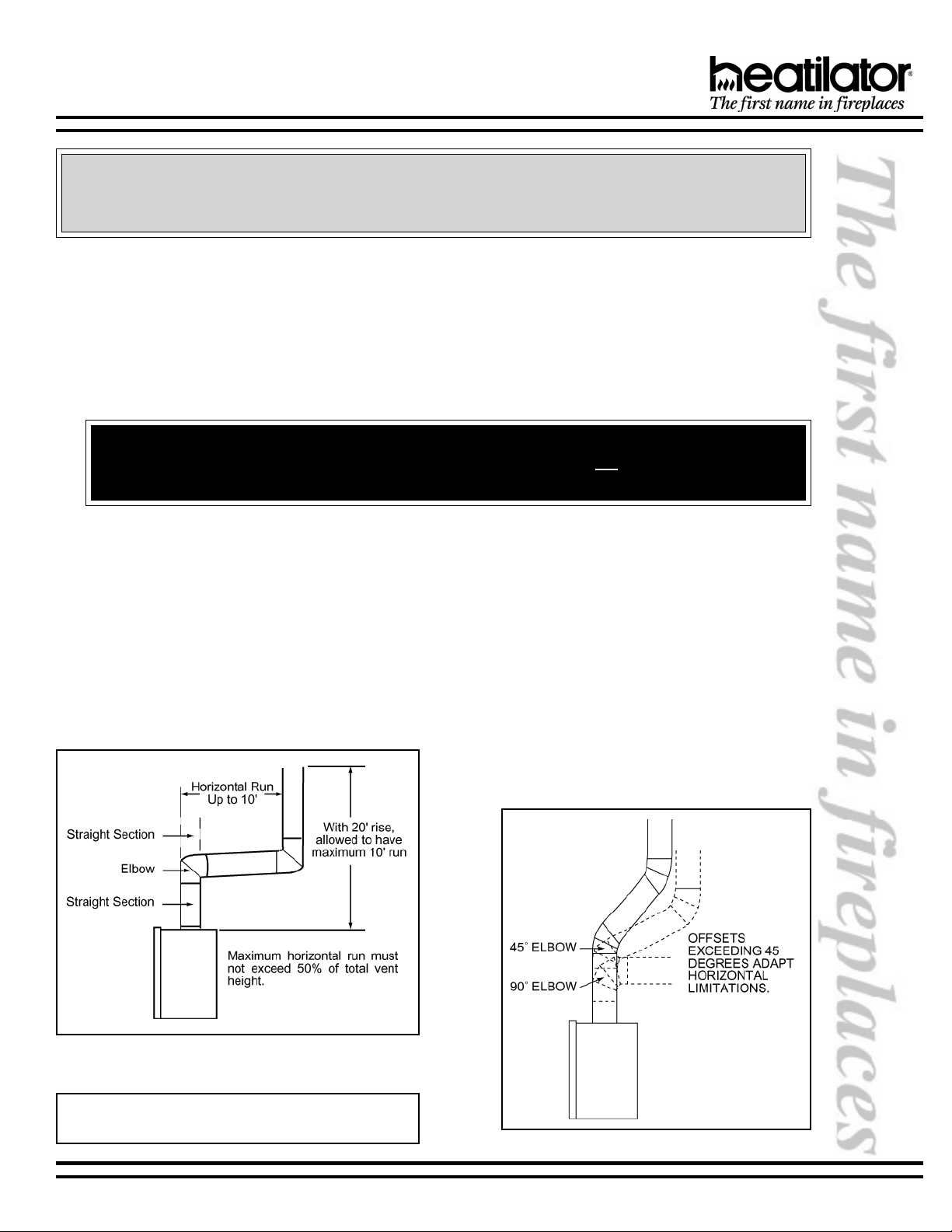
1. VENT HEIGHT
This appliance requires a 5 B-vent for operation.
Never downsize pipe. It must be terminated above
the roof line. Follow all B-vent requirements and
installation instructions, including minimum
clearances.
The minimum height of vent installation must be nine
feet from the top or twelve feet from the base of the
appliance. Horizontal run must never exceed 50% of
the height of the vent system as shown in Figure 4.
2. ATTACHING VENTING
a. Assembling Vent Sections. Attach straight vent
section to the top of appliance. Use only B-vent
sections.
b. Attaching the Vent to the Collar Shield. Three
tabs extend from the collar shield to the B-vent
section. Screw the tabs to the B-vent section using
the self-tapping ¼ screws supplied with the
appliance.
c. Using Elbows. Elbows exceeding 45° from the
vertical shall be considered horizontal and therefore
adapt horizontal run limitations. See Figure 5.
Figure 4
Venting Off the Top of Appliance
Note: Vertical rise off the top of the appliance before el-
bowing creates a less restrictive venting environment.
Figure 5 - Using Elbows
12-02 7 34615 Rev G
Page 8
NOVUS B-VENT INSTALLATION INSTRUCTIONS
WARNING - RISK OF FIRE!
Always maintain minimum clearances or greater
around the vent system. Do not pack air spaces with
insulation or other material. The flow of combustion
and ventilation air must not be obstructed.
WARNING!
The horizontal run of vent must have a 1/4 rise for
every 1 ft. of run towards the termination. Never allow the vent to run downward. This could cause high
temperatures and may present a fire hazard.
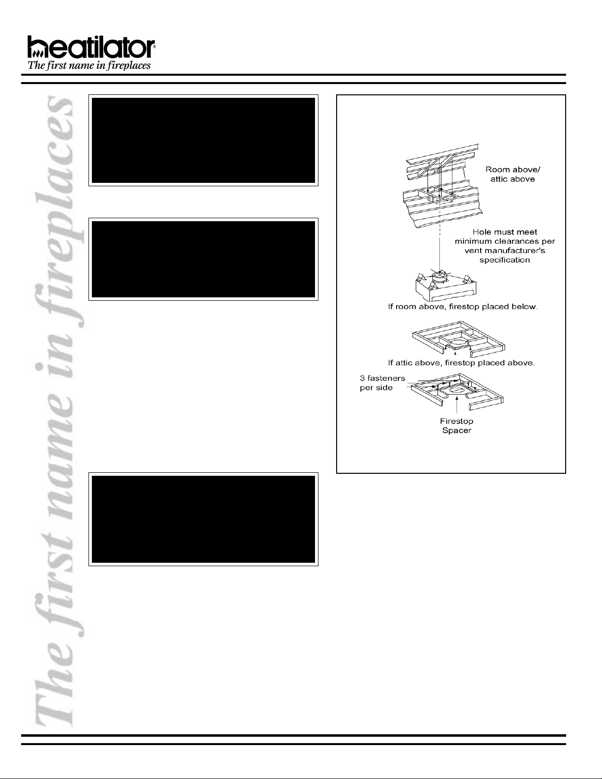
3. FIRESTOP SPACER/VENT INSTALLATION
Frame an opening and install a firestop spacer
whenever the vent penetrates a ceiling floor area, as
shown in Figure 6. Frame the opening with the same
sized lumber as used in the ceiling/floor joist. Unless
the flue is offset, the hole should be directly above the
appliance. DO NOT pack insulation around the vent.
Assemble vent sections with three screws per joint.
WARNING!
When vent sections exceeding three feet in length
are installed between an offset/return, structural support must be provided to reduce off-center loading
and prevent vent sections from separating at the vent
joints. Follow all B-vent manufacturer guidelines.
Figure 6
Installing the Firestop Spacer
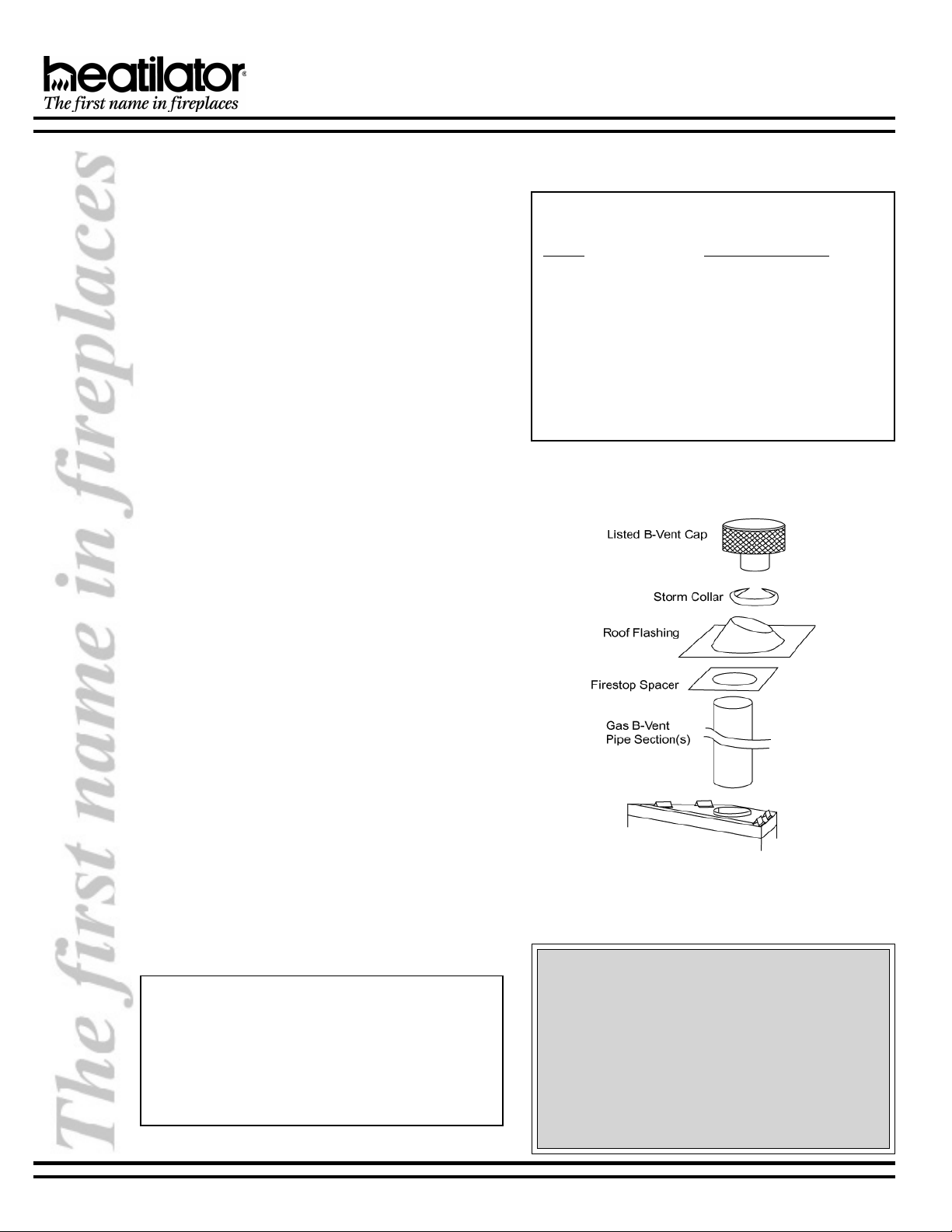
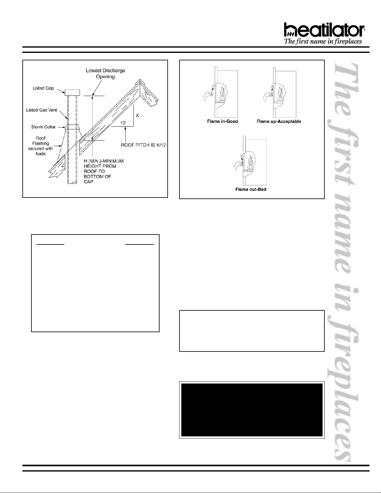
4. CHASE/TERMINATION INSTALLATION
Figure 7 and Table 1 specify minimum vent heights for
various pitched roofs. Vent sections may have to be cut
to a certain length.
These vent heights are necessary for safety and do not
ensure draft-free operation. Trees, buildings, adjoining
roof lines, adverse conditions, etc., may create a need
for a taller vent should down drafting occur.
34615 Rev G 8 12-02
Page 9
NOVUS B-VENT INSTALLATION INSTRUCTIONS
Figure 7
Vent Height for Vertical Termination
TABLE 1
Roof Pitch H (Min.) Ft.
Flat to 6/12 ................................................ 1.0
6/12 to 7/12 ............................................... 1.25
Over 7/12 to 8/12 ...................................... 1.5
Over 8/12 to 9/12 ...................................... 2.0
Over 9/12 to 10/12 .................................... 2.5
Over 10/12 to 11/12 .................................. 3.25
Over 11/12 to 12/12 .................................. 4.0
Over 12/12 to 14/12 .................................. 5.0
Over 14/12 to 16/12 .................................. 6.0
Over 16/12 to 18/12 .................................. 7.0
Over 18/12 to 20/12 .................................. 7.5
Over 20/12 to 21/12 .................................. 8.0
Vent Height
5. CHECK VENTING SYSTEM
Check the venting system to assure proper operation.
This can be done with a match while the appliance is
operating.
Hold a lighted match at the bottom edge of the draft hood
opening. If the flames and smoke remain upright,
ventilation is acceptable. If the flames and smoke are
drawn into the draft hood, this means ventilation is good.
If the flames and smoke are forced away from the draft
hood, this may indicate a ventilation blockage or down
draft resulting in gas spillage into the home. If this occurs,
turn off the appliance and do not burn it until it has been
inspected by a qualified service person. See Figure8.
Figure 8
Testing Ventilation
6. INSTALLING AN OUTSIDE AIR KIT (STRONGLY
RECOMMENDED)
An outside air kit should be purchased as a feature
with this appliance. An outside air kit helps to decrease
the amount of room air taken by utilizing outside air for
combustion. Figure 9 illustrates two of many possible
methods that can be used to supply outside air to the
appliance.
A maximum of 40 of air kit ducting is allowed. The air
kit must terminate at least one foot below the venting
termination and must terminate to the outside.
Note: The outside air kit can terminate at any level with
the exception that it must terminate at least one foot below the vent termination cap. The outside air kit inlet
thimble should be positioned at least four feet above the
ground level in a manner that will not allow snow, leaves,
etc. to block the inlet.
WARNING!
Exhaust products of gasoline engines are hazardous. The outside air must not be taken from a garage space, attic spaces, basements or above the
roofing where other heating appliances, fans or
chimneys exhaust or utilize air.
12-02 9 34615 Rev G
Page 10

NOVUS B-VENT INSTALLATION INSTRUCTIONS
Figure 10 - Air Kit Installation
Figure 9 - Outside Air Locations
a. The air kit can be installed only on the left side of
the appliance. See Figures 10 and 11 for correct
orientation of the door assembly and handle. The
hinge will be toward the back of the appliance.
b. Remove the cover plate or knockout from the side
of the appliance and discard.
c. Partly open the air kit door. The hinge on the door
assembly should be located toward the back of the
appliance. If the hinge is not positioned in this
manner, the door will not function correctly.
d. Attach the door assembly to the appliance using
the screws provided.
e. Bend down the left tab on the lower left glass
retainer. Insert the narrow end of the handle through
the tab and into the upper slot on the air kit door.
f. Check operation by pulling the handle out to open,
and pushing it in to close.
g. Mark and cut a hole in the building side for air entry.
This hole should allow some framing (two sides) so
the inlet tube assembly may be fastened properly.
h. Assemble the flexible duct (not supplied) between
the door assembly and the inlet tube assembly.
Secure it in position with the supplied wire ties.
Figure 11 - Door Assembly & Handle
34615 Rev G 10 12-02
Page 11

NOVUS B-VENT INSTALLATION INSTRUCTIONS
F. UTILITIES
1. HIGH ALTITUDE INSTALLATION
For U.S. installation, appliances are tested and
approved for elevations from 0-2000 feet. When
installing this appliance at an elevation above 2000
feet, National Fuel Gas Codes require a decrease of
the input rating by changing the existing burner orifice
to a smaller size. Input should be reduced 4% for each
1000 feet above sea level. Check with the local gas
utility for proper orifice size identification. Orifices are
available from your distributor.
For Canada, appliances are certified for elevations from
0-4500 feet. When installing this appliance at an
elevation between 0-4500 feet in Canada, the input
rating does not need to be reduced. When installing
this appliance at an elevation above 4500 feet in
Canada, check with local authorities.
2. GAS LINE CONNECTION
The appliance is provided with a stainless steel flexible
connector and manual shutoff valve. See Figure 12.
The incoming gas line should be piped into the valve
compartment and connected to the 1/2 FIP connection
provided on the manual shutoff valve. See Figure 13.
All connections must be tightened and checked for
leaks with a soap and water solution or leak detector.
Bleed the gas line to extract any air that may have
been trapped inside the pipe.
Figure 12 - Flexible Connector and Manual
Shutoff Valve
Note: The appliance and its manual shutoff valve must
be disconnected from the gas supply piping system during any pressure testing of that system at test pressures
in excess of 1/2 psi (3.5 kPa). The appliance must be
isolated from the gas supply piping system by closing its
manual shutoff valve during any pressure testing of the
gas supply piping system at test pressures equal to or
less than 1/2 psi (3.5 kPa).
3. GAS PRESSURE
On the standing pilot gas control valve and the
electronic valve, a pressure tap is included on the front
face of the valve.
Table 2 shows optimum gas pressure information.
Consult your local gas company for assistance in
determining the proper orifice for your altitude or refer
to ANSI Z223.1-latest edition, Appendix F.
4. FUEL
Do not burn wood or other material in this appliance.
Natural or propane gas conversions necessary to meet
the application need to be made by a qualified
technician using Hearth & Home Technologies
specified and approved parts.
In the event your standing pilot appliance must be
converted to use propane gas, you must use a CKVP
conversion kit. To convert to use natural gas, you must
use a CKVN conversion kit.
If your intermittent pilot appliance must be converted
to use natural gas, you must use a DCKN conversion
kit. To convert to propane, use a DCKP conversion Kit.
Figure 13 - Gas Line
WARNING!
This valve has been preset at the factory. Altering
settings may result in fire hazard or bodily injury.
TABLE 2
SUVON
.G.N-erusserpylppuSsagtelnI*).xaM(0.7-).niM(5.4
.G.N-erusserpdlofinaMmumitpO*5.3
.P.L-erusserpylppuSsaGtelnI*).xaM(0.41-).niM(0.11
.P.L-erusserpdlofinaMmumitpO*0.01
.G.N-etaRtupnI03CBNG.rh/UTB000,52
33CBNG.rh/UTB000,52
63CBNG.rh/UTB000,72
.P.L-etaRtupnI63/33CBNG.rh/UTB000,52
03CBNG.rh/UTB000,42
.G.N-eziSecifirO63CBNGmm65.2/.ni101.
33/03CBNGmm34.2/.ni690.
.P.L-eziSecifirO63/33/03CBNGmm05.1/.ni950.
nmulocretaw/sehcni*
12-02 11 34615 Rev G
Page 12

NOVUS B-VENT INSTALLATION INSTRUCTIONS
4. WIRING
a. Wall Switch
The installer shall supply a UL-listed or in Canada, a CSA-listed wall switch. This appliance was tested with
eighteen feet of UL listed 18 ga. Type CL2 105°C, two conductor thermostat wire. If other wiring materials are
used they shall comply with local codes. In the absence of local codes, they shall comply with the National
Electrical Code ANSI/NFPA 70-latest edition or Canadian Electrical Code CSA C22.1.
Note: This appliance must be electrically wired and grounded in accordance with local codes or, in the absence of local
codes, with National Electric Code ANSI/NFPA 70-latest edition or the Canadian Electric Code, CSA C2.1.
Note: Optional Accessories Requirements: Wiring for optional accessories should be done now to avoid reconstruction.
CAUTION:
Label all wires prior to disconnection when servicing controls. Wiring errors can cause improper and dangerous
operation. Verify proper operation after servicing.
b. Standing Pilot Ignition
This standing pilot appliance does not require a 110V AC supply to operate. It is suggested that a switched 110V
junction box be installed to power the optional remote control and/or fan.
Only heater listed appliances may be connected to a thermostat. Use a thermostat that is compatible with a millivolt
gas valve. See Figure14.
WARNING!
This appliance does NOT require a 110VAC supply for operations. Connecting the appliance/wall switch
to a 110V AC supply will cause the appliance to malfunction and destroy the valve and thermopile.
Figure 14 - Standing Pilot Ignition Wiring Diagram
34615 Rev G 12 12-02
Page 13

NOVUS B-VENT INSTALLATION INSTRUCTIONS
c. Intermittent Pilot Ignition
This appliance is equipped with an intermittent pilot control valve which operates on a 3 volt system. See wiring
diagram, Figure 15.
The appliance is supplied with a battery pack and a 3 volt AC transformer, which requires the installation of the
supplied junction box. It is highly recommended that the junction box be installed at this time to avoid reconstruction.
The battery pack requires two D cell batteries (not included). Batteries cannot be placed in the battery pack while
using the 3 volt AC transformer. Conversely, the transformer must be unplugged if the battery pack is used.
Note: This appliance must be electrically wired and grounded in
accordance with local codes or, in the absence of local codes, with
National Electric Code ANSI/NFPA 70-latest edition or the Canadian
Electric Code, CSA C221.1.
CAUTION:
Battery polarity must be correct or control
module damage will occur.
Figure 15 - Intermittent Pilot Ignition Diagram
d. Junction Box Wiring
We recommend you operate the two outlets on
separate circuits, one side hot full time, one side
switched. This allows independent operation of the
appliance and fan. Independent operation is
obtained by using minimum 14-3 with ground
Romex and separating the two outlets by breking
out the tab as shown in Figure 16.
6. JUNCTION BOX INSTALLATION INSTRUCTIONS
a. Remove the junction box assembly from the valve
compartment.
b. If the box is being wired from the OUTSIDE of the
appliance:
1) Loosen two screws on the Romex connector,
feed the necessary length of wire through the
connector and tighten the screws.
2) Make all necessary wire connections to the
receptacle and assemble the receptacle and
cover to the junction box.
12-02 13 34615 Rev G
3) Attach the junction box assembly to the
c. If the box is being wired from the INSIDE of the
appliance:
1) Pull the electrical wires from outside the
2) Loosen the two screws on the Romex
3) Make all necessary wire connections to the
4) Attach the junction box assembly to the inside
d. If the box is not to be wired at the time of appliance
installation, assemble the receptacle and cover to
the box and install on the inside of the appliance.
Figure 16 - Junction Box Detail
outside of the appliance with the two screws
provided.
appliance through this opening into the valve
compartment.
connector, feed the necessary length of wire
through the connector and tighten the screws.
receptacle and assemble the receptacle and
cover to the junction box.
of the appliance with the two screws provided.
Page 14

NOVUS B-VENT INSTALLATION INSTRUCTIONS
G. FINISHING
1. COMBUSTIBLE FINISHING MATERIAL
Material made of or surfaced with wood, compressed
paper, plant fibers, plastics, or any material capable of
igniting and burning, whether flame proofed or not,
plastered or unplastered (this includes drywall).
2. NONCOMBUSTIBLE FINISHING MATERIAL
Material which will not ignite and burn. Such materials
are those consisting entirely of steel, iron, brick, tile,
concrete, slate, glass or plasters, or combination thereof,
or have a UL Fire rating of Zero (0).
3. HIGH TEMPERATURE SEALANT MATERIAL
Sealants that will withstand high temperatures: General
Electric RTV103 (Black) or equivalent. Rutland, Inc.
Appliance Mortar #63, or equivalent.
A high temperature sealant, 1/8 inch wide minimum,
must be used to close off gaps between the appliance
and facing to prevent cold air leaks. See Figure 17.
Figure 17 - Finishing Materials
WARNING!
Grilles on this appliance cannot, in any way, be covered as it may create a fire hazard.
Note: If an optional fan or hand held remote control
are to be used, wiring must be done prior to finishing
to avoid reconstruction.
H. APPLIANCE PREPARATION
1. ATTACHING THE HOOD
The hood is to be located above the glass panel. The
hood must be attached or a fire hazard may result.
Locate the four screws just inside the upper section of
the appliance. Position the hood and slide into position.
Tighten the four screws. See Figure18.
2. UPPER GRILLE PANEL REMOVAL
Grasp the upper grille panel and remove the rubber
pins holding the grille. See Figure 19.
3. CONTROL ACCESS PANEL REMOVAL
Release the spring pin on the right hand side of the
control access panel. See Figure 20.
Note: The remote wall switch must be wired prior to
applying the finishing material in order to avoid
reconstruction.
4. GLASS AND SCREEN REMOVAL
See page 21 of this manual.
Figure 19 - Upper Grille Panel Removal
Figure 18 - Hood Placement
34615 Rev G 14 12-02
Figure 20 - Control Access Panel Removal
Page 15

NOVUS B-VENT INSTALLATION INSTRUCTIONS
5. APPLIANCE PREPARATION
a. Log Set
Remove the two shipping bands from the log set
(Figure 21a) and reassemble. The log set should
look similar to that in Figure21b.
Figure 21a - Log Set for NOVUS
c. Placing the Rock Wool
Place a small amount of 1/2 diameter pieces (dimesize) of rock wool on the burner pan so that the
rock wool touches but does not cover the holes in
the burner pan. This will provide the glowing
embers look. See Figure 22.
6. GLASS AND SCREEN REPLACEMENT
See page 21 of this instruction manual.
7. CONTROL ACCESS PANEL REPLACEMENT
Place the control access panel as shown in Figure23.
Figure 21b - Log Set for NOVUS
b. Placing the Lava Rock and Vermiculite
See Figure 22 for lava rock and vermiculite
placement.
WARNING - RISK OF CARBON MONOXIDE!
Do not hit or strike glass. Do not operate this appliance with the glass removed, broken or not sealed.
I. DETERMINING THE IGNITION TYPE
To determine whether your appliance is an intermittent pilot
ignition or a standing pilot ignition, open the control access
panel (Figure 23) to examine the wiring system. If your system
has a red ignitor button, as shown in Figure 24, you own a
standing pilot ignition appliance. If no red ignitor button is
present, you own an intermittent pilot ignition appliance.
You may also check the rating label located on the inside of
the control access panel to determine ignition type.
Figure 22
Placing the Vermiculite, Lava Rock and Rock Wool
(logs removed for clarity)
Figure 23 - Replacing the Control Access Panel
Figure 24 - Standing Pilot Ignition
12-02 15 34615 Rev G
Page 16

NOVUS B-VENT INSTALLATION INSTRUCTIONS
J. LIGHTING INSTRUCTIONS
1. INTERMITTENT PILOT IGNITION
FOR YOUR SAFETY
READ BEFORE OPERATING
WARNING!
If you do not follow these instructions exactly, a fire or explosion may result causing property damage, personal injury or loss of life.
A. This appliance is equipped with an ignition device which automatically lights the pilot. Do not try to light the pilot by
hand.
B. BEFORE LIGHTING smell all around the appliance area for gas. Be sure to smell next to the floor because some
gas is heavier than air and will settle on the floor.
WHAT TO DO IF YOU SMELL GAS:
Do not try to light any appliance.
Do not touch any electric switch; do not use any phone in your building.
Immediately call your gas supplier from a neighbors phone. Follow the suppliers instructions.
If you cannot reach your gas supplier, call the fire department.
C. Use only your hand to close the gas line. Never use tools. If the knob will not push in or turn by hand, dont try to
repair it; call a qualified service technician. Force or attempted repair may result in a fire or explosion.
D. Do not use this appliance if any part has been under water. Immediately call a qualified service technician to
inspect the appliance and to replace any part of the control system and any gas control which as been under
water.
INTERMITTENT PILOT IGNITION LIGHTING INSTRUCTIONS
1. Turn wall switch to the OFF position.
2. This appliance is equipped with an ignition device which automatically lights the pilot. Do not try to light the pilot by
hand.
3. Open control access panel and turn manual shutoff valve to CLOSED.
4. Wait five minutes to clear out any gas. If you then smell gas, STOP! Follow B in the safety information above on
this label. If you do not smell gas, go on to the next step.
5. Turn the manual shutoff valve to OPEN.
6. Turn the wall switch to the ON position.
7. If the appliance will not operate, follow the instructions TO TURN OFF THE GAS TO THE APPLIANCE and call
your service technician or gas supplier.
8. If using the battery pack and the appliance will not operate, check the batteries for sufficient charge and replace if
necessary.
TO TURN OFF THE GAS TO THE APPLIANCE
1. Turn off the wall switch.
2. Open control access panel. Turn manual shutoff valve
to the CLOSED position. Do NOT force.
3. Close control access panel.
34615 Rev G 16 12-02
Page 17

NOVUS B-VENT INSTALLATION INSTRUCTIONS
2. STANDING PILOT IGNITION
FOR YOUR SAFETY READ BEFORE LIGHTING THE STANDING PILOT.
WARNING!
If you do not follow these instructions exactly, a fire or explosion may result causing property damage,
personal injury or loss of life.
A. This appliance has a pilot which must be lighted by hand. When lighting the pilot, follow these instructions exactly.
B. BEFORE LIGHTING smell all around the appliance area for gas. Be sure to smell next to the floor because some gas is
heavier than air and will settle on the floor.
WHAT TO DO IF YOU SMELL GAS
Do not try to light any appliance.
Do not touch any electric switch; do not use any phone in your building.
Immediately call your gas supplier from a neighbors phone. Follow the suppliers instructions.
If you cannot reach your gas supplier, call the fire department.
C. Use only your hand to push in or turn manual shutoff valve. Never use tools. If the manual shutoff valve will not push in or
turn by hand, dont try to repair it; call a qualified service technician. Force or attempted repair may result in a fire or
explosion.
D. Do not use this appliance if any part has been under water. Immediately call a qualified service technician to inspect the
appliance and to replace any part of the control system and any gas control which as been under water.
LIGHTING INSTRUCTIONS
STOP! READ THE SAFETY INFORMATION ABOVE ON THIS LABEL!
1. Turn off all wall switches to the appliance. Set
thermostat to lowest setting
2. Open control access panel.
3. Turn manual shutoff valve to CLOSED. Wait 5
minutes to clear out any gas. Then smell for gas,
including near the floor. If you smell gas, STOP! Follow
B in the safety information above on this label. If you
dont smell gas, go to the next step.
4. Turn manual shutoff valve to OPEN.
5. Turn pilot knob clockwise to OFF. Knob may have
to be depressed to pass the PILOT position.
6. Locate pilot assembly inside appliance.
7. Locate red ignitor button.
8. Turn pilot knob to PILOT and push in.
9. Continue to hold in pilot knob and push the red ignitor
button 12-15 times until small blue pilot flame appears.
10. Continue to hold in pilot knob for approximately one
minute. Pilot should remain lit. If pilot goes out, wait 5
minutes and repeat Steps 4-9.
11. Release and turn the knob counterclockwise to ON.
To light main burner, turn wall switch to ON. Do not
light by hand.
12. If the appliance will not operate, follow the instructions
To Turn Off Gas To Appliance and call your service
technician or gas supplier.
Note: To light main burner, turn the wall switch
to ON. Do not light by hand.
TO TURN OFF THE GAS TO THE
APPLIANCE
1. Turn off the wall switch or set thermostat to lowest
setting.
2. Open control access panel.
3. Turn the manual shutoff valve to CLOSED position.
Do not force.
4. Close control access panel.
12-02 17 34615 Rev G
Page 18

NOVUS B-VENT INSTALLATION INSTRUCTIONS
K. SEASONAL CHECKLIST
WARNING!
Children and adults should be alerted to the hazards of high surface temperatures and should stay away to avoid
burns or clothing ignition. Young children should be carefully supervised when they are in the same room as the
appliance.
CAUTION:
Any safety screen or guard removed for servicing an appliance must be replaced prior to operating this appliance.
Clothing or other flammable material should not be placed on or near the appliance.
Installation and repair should be done by a qualified service
person. The appliance should be inspected before use and
at least annually by a qualified service person. More frequent cleaning may be required due to excessive lint from
carpeting, bedding material, etc. It is imperative that control
compartments, burners and circulating air passageways of
the appliance be kept clean.
BEFORE OPERATING THIS APPLIANCE HAVE
A QUALIFIED TECHNICIAN:
* Review proper placement of logs, rock wool, lava
rock and vermiculite.
* Check the wiring.
* Check the air shutter adjustment.
* Ensure that there are no gas leaks.
* Ensure that the glass is sealed and in the proper
position.
* Ensure that the flow of combustion and ventilation
air is not obstructed.
WARNING!
Keep the area near the appliance clear and free from
combustible materials, Gasoline and other flammable
vapors and liquids.
WARNING!
Do not use this appliance if any part has been under
water. Immediately call a qualified service technician
to inspect the appliance and to replace any part of
the control system and any gas control which has
been under water.
1. STANDING PILOT IGNITION OPERATION
a. Hearth & Home Technologies recommends you
leave the pilot on year round.
b. Lighting the Appliance During Regular Use
Turn the wall switch to ON.
c. Shutdown During Regular Use
Turn the wall switch to OFF.
d. Long Term Shutdown
1) Turn all wall switches to OFF.
2) Turn pilot knob on valve to OFF.
3) Turn the gas line to CLOSED.
4) To relight the pilot and appliance, see page 17.
2. INTERMITTENT PILOT IGNITION OPERATION
a. Lighting the Appliance During Regular Use
Turn the wall switch to ON.
b. Shutdown During Regular Use
Turn the wall switch to OFF.
c. Long Term Shutdown
1) Turn all wall switches to OFF.
2) Turn the manual shutoff valve to CLOSED.
3) To relight the appliance, see page 16.
3. FUEL
Do not burn wood or other material in this appliance.
Natural or propane gas conversions necessary to
meet the application need to be made by a qualified
technician using Hearth & Home Technologies
specified and approved parts.
In the event your standing pilot appliance must be
converted to use propane gas, you must use a CKVP
conversion kit. To convert to use natural gas, you must
use a CKVN conversion kit.
If your intermittent pilot appliance must be converted
to use natural gas, you must use a DCKN conversion
kit. To convert to propane, use a DCKP conversion
kit.
34615 Rev G 18 12-02
Page 19

NOVUS B-VENT INSTALLATION INSTRUCTIONS
4. OUTSIDE AIR KIT OPERATION
The outside air kit should be purchased with this
appliance. The outside air kit helps to decrease the
amount of room air taken, by utilizing outside air for
combustion. It is strongly recommended that it be
installed.
To operate the outside air kit, before starting the
appliance, open the control access panel. Grasp the
small, black handle located on the left side of the
appliance, just below the glass retainer. See Figure25.
Lift the handle out of its slot and pull towards the front.
The outside air door should open. Replace the handle
back in the slot on the bracket from which it was removed
(so the outside air door remains open) and close the
control access panel. When through burning the
appliance, open the panel, grasp the handle and push
the outside air door closed.
Figure 25 - Outside Air Kit Operation
L. START-UP ISSUES
:seussI:snoituloSdnasesuaCelbissoP
.1.ssalgehtnonoitasnednoC.1sA.snoitairaverutarepmetdnanoisubmocsagfotluserasisihT
.raeppasiddluohsnoitasnednocsiht,pusmrawecnailppaeht
.2.semalfeulB.2otnigeblliwsemalfehtdnanoitarepolamronfotluserasisihT
.nrubotdewollasiecnailppaehtsawolley
.3.ecnailppaehtmorfrodO.3tsrifehtrofrodonaesaeleryamecnailppasiht,detarepotsrifnehW
ehtdnatniapehtfognirucehtybdesuacsisihT.sruohlareves
.gnirutcafunammorfgniniamerslioynafoffogninrub
.4.ssalgehtnomliF.4.sgoldnatniapehtfossecorpgnirucehtfotluserlamronasisihT
otgninrublaitinifosruoh6-4nihtiwdenaelcebdluohsssalG
.yrassecenebyamossarBsahcus,renraelcevisarba
WARNING!
Never use gasoline, gasoline-type lantern fuel, kerosene, charcoal lighter fluid or similar liquids in this appliance.
Keep any flammable liquids a safe distance from the appliance.
-nonA.ssecorpgnirutcafunamehtmorfslioybtfelstisopedevomer
12-02 19 34615 Rev G
Page 20

NOVUS B-VENT INSTALLATION INSTRUCTIONS
M. MAINTENANCE INSTRUCTIONS
1. CLEANING THE BURNER AND CONTROL
COMPARTMENT
Keep the burner and control compartment clean by
brushing and vacuuming at least once a year. Failure to
do this may shorten the fans life (where applicable).
Always turn off the wall switch (or remote control) and
gas valve before cleaning.
2. CHECKING FLAME PATTERNS
Visually check the flame of the burner periodically,
making sure the flames are steady, not lifting or floating.
The flame color should be blue with yellow tips. The
sensor (intermittent pilot) or thermopile and
thermocouple (standing pilot) tips should be covered
with flame. See Figures 26 and 27.
If the vent configuration is installed incorrectly, the vent
may cause the flames inside the appliance to lift or
ghost, which is a dangerous situation. Inspect the
flames after installation to ensure proper performance.
See Figure 28. If the vent configuration is correct, yet
the flames are lifting or ghosting, shut off gas to the
appliance and contact the dealer you purchased the
appliance from.
Figure 27
Standing Pilot
Note: The look of the flames and embers may differ based
on the type of fuel and venting assembly that is required.
Figure 26
Intermittent Pilot Ignition Assembly
Figure 28
Flame Patterns
34615 Rev G 20 12-02
Page 21

NOVUS B-VENT INSTALLATION INSTRUCTIONS
3. VENTING SYSTEM INSPECTION
The appliance and venting system should be inspected
before use, and at least annually, by a qualified field
service person, to ensure that the flow of combustion
and ventilation air is not obstructed.
4. CLEANING THE GLASS
See Figure 29.
Never operate this appliance without the glass properly
secured in place or if the glass is broken.
In the event of glass breakage, carefully remove the
glass frame. This will allow the removal of all glass
fragments and sheet metal edge protection strips.
Vacuum all remaining glass pieces with a shop vac.
DO NOT VACUUM IF PIECES ARE HOT! Replace
glass with only a Heatilator glass panel assembly
ordered direct or through your local distributor. Never
use substitute material. Only fully tempered soda lime
safety glass may be used on this appliance.
Figure 29 - Glass Cleaning
5. LOG REMOVAL/REPLACEMENT
If removal of the logs becomes necessary, remove the
two screws at the front of the grate. Grasp the two outside
upright grate bars. Pull the log set toward the front and
up, off the burner. See Figure 30.
To replace the log set, grasp the two outside upright grate
bars. Push and lower the log set onto the burner pan,
making sure the back of the left most grate bar slides
through the grate mounting bracket attached to the
hearth pan. Attach the two screws at the front of the
grate.
Safety Note:
Handle glass with care to
avoid striking, scratching or
slamming shut. NEVER
clean glass when hot. Keep
children and pets a safe
distance away.
Figure 30 - Log Removal
12-02 21 34615 Rev G
Page 22

N. OPTIONAL COMPONENTS
BC10
Fan Motor Rheostat Control
BC14
Automatic Variable Blower
Control
NOVUS B-VENT INSTALLATION INSTRUCTIONS
RC-SMART-HTL
Remote Control
RC-BATT-HTL
Battery-operated Remote Control
(Standing Pilot)
RCT-MLT-HTL
Multi-Function
Remote Control
SMART-STAT-HTL
Remote Control with
Thermostat Control
SMART-BATT-HTL
Battery-operated Remote Control
with Thermostat Control
FK4
Fan Kit
(33 & 36 appliances only)
FK21
Fan Kit (30 appliances only)
WSK-MLT-HTL
Multi-Function Wall Switch
DFN0B/S
DFN3B/S
DFN6B/S
Fixed Glass Door
AK14
Outside Air Kit
(strongly recommended)
DFBN36
Fixed Bay Door
(36 Appliances only)
MF1
Adjustable Flame Control
(Natural Gas Standing Pilot
MF2
Adjustable Flame Control
(Propane Gas Standing Pilot)
DFA30/B
DFA33/B
DFA36/B/S
Fixed Cabinet Style
Arched Glass Door
34615 Rev G 22 12-02
Page 23

NOVUS B-VENT INSTALLATION INSTRUCTIONS
ROBERTSHAW STANDING PILOT CONVERSION KITS
CKVN Conversion Kit
(propane to natural gas)
INTERMITTENT PILOT CONVERSION KITS
DCKN Propane to
Natural Gas
Conversion Kit
(Intermittent Pilot)
CKVP Conversion Kit
(natural gas to propane)
DCKP Natural Gas
to Propane
Conversion Kit
(Intermittent Pilot)
12-02 23 34615 Rev G
Page 24

NOVUS B-VENT INSTALLATION INSTRUCTIONS
TKN03B/S, TKN33B/S,TKN63B/S
Trim Kits
TKN05B/S, TKN35B/S, TKN65B/S
Trim Kits
TKB6
Bay Door Trim Kit
QKE1B
QKE2B
Quick Tile Brass Surround
34615 Rev G 24 12-02
Page 25

NOVUS B-VENT INSTALLATION INSTRUCTIONS
O. REPLACEMENT PARTS
Replacement parts are available from your distributor/dealer.
6
#metI#traPnoitpircseD.ytQ
1
2
3
4
5
6
32122
22122
12122
39912
29912
19912
40862
30862
20862
32542
22542
12542
28512
18512
08512
15043
32943
"63-ellirGreppU
"33-ellirGreppU
"03-ellirGreppU
"63-dooH
"33-dooH
"03-dooH
"63-ylbmessAneercS
"33-ylbmessAneercS
"03-ylbmessAneercS
"63-emarF/wssalG
"33-emarF/wssalG
"03-emarF/wssalG
"63-ellirGrewoL
"33-ellirGrewoL
"03-ellirGrewoL
teSgoLsuvoN"63/33
teSgoLsuvoN"03
1
1
1
1
1
1
1
1
1
1
1
1
1
1
1
1
1
Visit our Website @www.heatilator.com
for a dealer/distributor near you!
12-02 25 34615 Rev G
Page 26

NOVUS B-VENT INSTALLATION INSTRUCTIONS
Homeowners Notes Page
34615 Rev G 26 12-02
Page 27

NOVUS B-VENT INSTALLATION INSTRUCTIONS
Index
A
Air Kit 22
Installation 9, 10
Operation 19
Appliance Preparation
Attaching the Hood 14
Glass & Screen Removal 14, 21
Lava Rock 15
Log Set 15
Rock Wool 15
Upper Grille Removal 14
Vermiculite 15
B
Blue Flames 19
BTUs 11
Burner and Control Compartment 20
C
Certification 4
Chase 8
Clean
Burner & Control Compartment 20
Glass 21
Clearances 5, 6
Codes 4
Electric 12, 13
Gas 4, 11
Collar Shield 7
Combustible Finishing Material 14
Conversion Kit 11
Conversion Kits 18, 23
E
Elbows, using 7
Electric Codes 12, 13
F
Finishing Material
Combustible 14
High Temperature Sealant 14
Noncombustible 14
Firestop Spacer 8
Flame Patterns 20
Framing 6
Fuel 18
Fuel Conversion 11, 18
G
Gas Codes 4, 11
Glass
Certifications/Specifications 4
Condensation 19
Film on 19
H
High Temperature Sealant 14
Hood 14
I
Ignition
Determining the Type 15
Intermittent Pilot 18
Standing Pilot 18
Input Rate 11
J
Junction Box Installation 13
Junction Box Wiring 13
L
Lava Rock 15
Lighting Instructions
Intermittent Pilot 16
Standing Pilot Ignition 17
Location 5
Locations 6
Log Removal/Replacement 21
Log Set 15, 25
M
Maintenance
Burner & Control Compartment 20
Flame Patterns 20
Mantel 6
N
Nomenclature 5
Noncombustible Finishing Material
14
O
Odor 19
Optional Components 22
Outside Air Kit 22
Installation 9, 10
Operation 19
R
Replacement Parts 25
Rock Wool 15
S
Seasonal Checklist 18
Fuel 18
Intermittent Pilot Operation 18
Standing Pilot Ignition Operation
18
Space Requirements 6
Standing Pilot Ignition
Operation 18
Start-up Issues
Blue Flames 19
Condensation on Glass 19
Film on Glass 19
Odor 19
T
Termination Installation 8
U
Upper Grille 14
Utilities
Gas Line Connection 11
Gas Pressure 11
High Altitude Installation 11
Wiring 12
Intermittent Pilot Ignition 13
Standing Pilot Ignition 12
V
Ventilation 9
Venting
Attaching to the Appliance 7
Check the System 9
System Inspection 21
Vent Height 7
Vermiculite 15
Vertical Installation 4
W
Wall Switch 12, 22
Wiring
Intermittent Pilot Ignition 13
Standing Pilot Ignition 12
12-02 27 34615 Rev G
Page 28

Gas Appliance (Fireplace)
Limited Lifetime Warranty
HEARTH & HOME TECHNOLOGIES (HHT) extends the following warranty for HEATILATORâ gas appliances installed in the
United States of America or Canada (the Appliance). Dealers and employees of HHT have no authority to make any warranty or authorize
any remedies in addition to or inconsistent with the terms of this warranty.
Limited Lifetime Warranty.
HHT warrants the Appliance for component failure due to a manufacturing defect of any of the following components: combustion chamber,
burner pan, and logs. The Limited Lifetime Warranty specified above is subject to the conditions, exclusions and limitations listed below, is
for the period the Appliance is owned by the original homeowner only, and is nontransferable.
1 Year Limited Warranty.
HHT warrants the Appliance to be free from failure of any of the following components for a period of one year after installation: valve,
flexible gas line connector, glass panel, fan, direct vent chimney components, factory paint, gasket, piezo ignitor, thermopile, thermocouple,
junction box, pilot assembly, shutoff valve, high limit switch, refractory liners, transformer, and control box. If the Heatilator Appliance is
found to be defective in either material or workmanship within one year of the date of original installation, HHT will provide replacement
parts at no charge and pay reasonable labor and freight costs, and is for the period of one year following the date of original installation of
the Appliance.
Conditions, Exclusions, & Limitations of Liability.
A. Both the Limited Lifetime and 1 Year Limited Warranties supplied by HHT apply only while the Appliance is in its location of
original installation. HHTs obligation under this warranty does not extend to damages resulting from (1) installation, operation or
maintenance of the Appliance not in accordance with the Installation Instructions, Operating Instructions, and the Listing Agent
Identification Label furnished with the Appliance; (2) installation which does not comply with local building codes; (3) shipping,
improper handling, improper operation, abuse, misuse, accident or unworkmanlike repairs; (4) environmental conditions, inadequate ventilation or drafting caused by tight sealing construction of the structure, air handling devices such as exhaust fans or
forced air furnaces, or other causes; (5) use of fuels other than those specified in the Operating Instructions; (6) installation or
use of components not supplied with the Appliance or any other components not expressly authorized and approved by HHT;
and/or (7) modification of the Appliance not expressly authorized and approved by HHT in writing. This warranty is limited to only
the component parts manufactured or supplied by HHT.
B. HHTs liability under both the Limited Lifetime Warranty and the 1 Year Limited Warranty is limited to the replacement and repair
of defective components or workmanship during the applicable period. HHT may fully discharge all of its obligations under such
warranties by repairing the defective component(s) or at HHTs discretion, providing replacement parts at no charge and paying
reasonable labor and freight costs.
C. EXCEPT TO THE EXTENT PROVIDED BY LAW, HHT MAKES NO EXPRESS WARRANTIES OTHER THAN THE WARRANTY
SPECIFIED HEREIN. THE DURATION OF ANY IMPLIED WARRANTY IS LIMITED TO DURATION OF THE WARRANTY
SPECIFIED ABOVE.
D. Some states do not allow exclusions or limitations of incidental or consequential damages, so those limitations may not apply to
you. This warranty gives you specific rights; you may also have other rights which vary from state to state.
How to Obtain Service.
To obtain service under this warranty you must:
1. Send written notice of the claimed condition to Heatilator Technical Service Department, Hearth & Home Technologies,
1915 W. Saunders Street, Mt. Pleasant, Iowa 52641-1563. You may also register your claim online at www.heatilator.com/
contact.asp.
2. Provide proof of purchase, model number, serial number, and manufacturing date code to HHT.
3. Provide HHT reasonable opportunity to investigate the claim, including reasonable opportunity to inspect the Appliance
prior to any repair or replacement work and before the Appliance or any component of the Appliance has been removed
from the place of original installation.
4. Obtain HHTs consent to any warranty work before the work is done.
ADDITIONAL INFORMATION. If you would like information on current HEATILATOR products or want to locate a dealer in your area, call
1-800-843-2848.
ã2001 Heatilatorâ is a Registered Trademark of Hearth & Home Technologies
34615 Rev G 28 12-02
 Loading...