

Hearth and Home Technologies CFL-18NG-C, CFL-24LP-C, CFL-24NG-IPI, ST-CFL-24LP-B, CFL-24LP-IPI User Manual
...Page 1
MODELS:
NATURAL GAS PROPANE
CFL-18NG-C CFL-18LP-C
CFL-24NG-C CFL-24LP-C
CFL-30NG-C CFL-30LP-C
ST-CFL-24NG-B ST-CFL-24LP-B
CFL-24NG-IPI CFL-24LP-IPI
Owner’s Manual
Installation and Operation
CAUTION
DO NOT DISCARD THIS MANUAL
• Important operating
and maintenance
instructions included.
WARNING: If the information in these
instructions is not followed exactly, a fi re
or explosion may result causing property
damage, personal injury, or death.
• Do not store or use gasoline or other fl am-
mable vapors and liquids in the vicinity of
this or any other appliance.
• What to do if you smell gas
- Do not try to light any appliance.
- Do not touch any electrical switch. Do not
use any phone in your building.
- Immediately call your gas supplier from a
neighbor’s phone. Follow the gas supplier’s instructions.
- If you cannot reach your gas supplier, call
the fi re department.
• Read, understand and follow
these instructions for safe
installation and operation.
DO NOT
DISCARD
• Leave this manual with
party responsible for use
and operation.
WARNING
HOT SURFACES!
Glass and other surfaces are hot during
operation AND cool down.
Hot glass will cause burns.
• Do not touch glass until it is cooled
• NEVER allow children to touch glass
• Keep children away
• CAREFULLY SUPERVISE children in same room as
fi replace.
• Alert children and adults to hazards of high temperatures.
High temperatures may ignite clothing or other fl ammable
materials.
• Keep clothing, furniture, draperies and other fl ammable
materials away.
This appliance has been supplied with an integral barrier
to prevent direct contact with the fi xed glass panel. DO
NOT operate the appliance with the barrier removed.
Contact your dealer or Hearth & Home Technologies if the
barrier is not present or help is needed to properly install one.
• Installation and service must be performed
by a qualifi ed installer, service agency , or the
gas supplier.
In the Commonwealth of Massachusetts:
• Installation must be performed by a licensed plumber
or gas fi tter.
• The chimney fl ue damper, when used with gas logs,
will be welded open or completely removed.
• A CO detector shall be installed in the room where the
appliance is installed.
Heat & Glo • CFL-18/24/30-C, CFL-24-IPI, ST-CFL-24-B • 526-910 Rev. E • 10/08
Installation and service of this appliance should be
performed by qualifi ed personnel. Hearth & Home
Technologies suggests NFI certifi ed
or factory trained professionals, or
technicians supervised by an NFI
certifi ed professional.
1
Page 2
Read this manual before installing or operating this appliance.
Please retain this owner’s manual for future reference.
Congratulations
Congratulations on selecting a Heat & Glo gas appliance
—an elegant and clean alternative to wood burning
appliances. The Heat & Glo gas appliance you have
selected is designed to provide the utmost in safety,
reliability, and effi ciency .
As the owner of a new appliance, you’ll want to read and
carefully follow all of the instructions contained in this
Owner’s Manual. Pay special attention to all Cautions and
Warnings.
Homeowner Reference Information
This Owner’s Manual should be retained for future
reference. We suggest that you keep it with your other
important documents and product manuals.
The information contained in this Owner’s Manual, unless
noted otherwise, applies to all models and gas control
systems.
Your new Heat & Glo gas appliance will give you years of
durable use and trouble-free enjoyment. Welcome to the
Heat & Glo family of appliance products!
We recommend that you record the following pertinent
information about your appliance.
Model Name: ___________________________________________ Date purchased/installed: __________________
Serial Number: __________________________________________ Location on appliance: ____________________
Dealership purchased from: _______________________________ Dealer Phone: __________________________
Notes: _______________________________________________________________________________________
_____________________________________________________________________________________________
Listing Label Information/Location
This product may be covered by one or more of the following patents: (Nos produits sont couverts par un ou plusieurs des brevets suivants): (United States)
4593510,4686807, 4766876, 4793322, 4811534,5000162,5016609,5076254, 5113843,5191877, 5218953, 5263471, 5328356,5341794, 5347983, 5429495,
5452708,5542407,5601073, 5613487, 5647340, 5688568, 5762062, 5775408, 5890485, 5931661, 5941237, 594711 2,5996575, 6006743, 6019099, 6048195,
6053165, 6145502, 6170481, 6237588, 6296474, 6374822, 6413079, 6439226, 6484712, 6543698, 6550687, 6601579, 6672860, 6688302B2, 6715724B2,
6729551, 6736133, 6748940, 6748942, D320652, D445174, D462436; (Canada)1297749, 2195264, 2225408; or other U.S. and foreign patents pending (ou
autresbrevets americains et etrangers en attente).
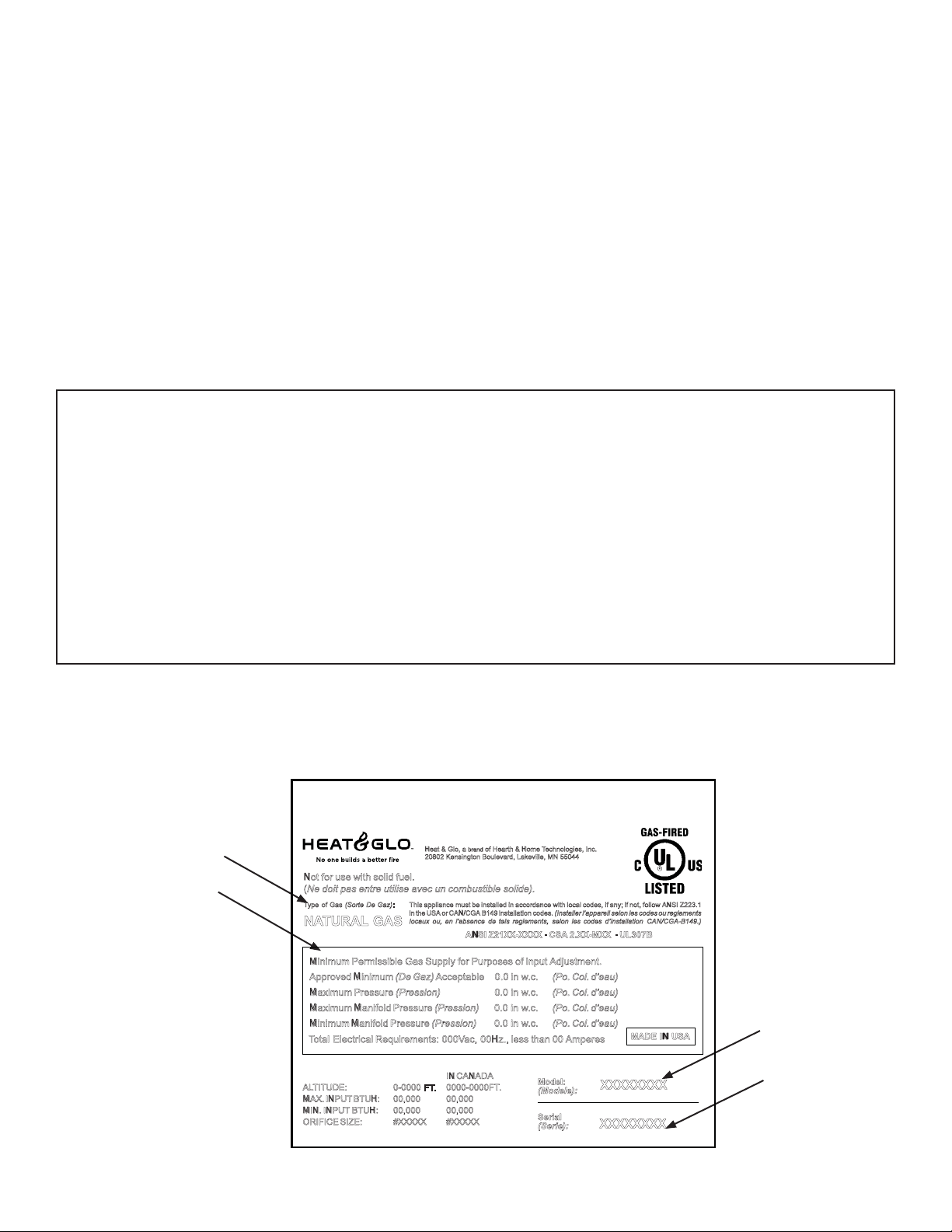
Type of Gas
Gas Information
Not for use with solid fuel .
(Ne doit pas entre utilise avec un combustible solide).
Ty pe of Gas (Sorte De Gaz) :
NATURA L GAS
Minimum Permissible Gas Supply for Purpos es of Input Adjustment .
Approved Minimum (De Gaz) Acceptabl e 0. 0 in w. c. (Po. Col. d’eau)
Maximum Pressure (Pression) 0. 0 in w. c. (Po. Col. d’eau)
Maximum Manifold Pressure (Pression) 0. 0 in w. c. (Po. Col. d’eau)
Minimum Manifold Pressure (Pression) 0. 0 in w. c. (Po. Col. d’eau)
T o tal Electrical Requirements: 000V ac, 00Hz., less than 00 Ampere s
AL TI TUDE : 0-0000 FT . 0000-0000FT .
MAX. INPU T BTUH: 00,000 00,000
MIN. INPU T BTUH: 00,000 00,000
ORIFICE SIZE: #XXXXX #XXXXX
The model information regarding your specifi c appliance can be found on
the rating plate usually located in the control area of the appliance.
He at & Gl o, a of Hearth & Ho me Te chnologies, Inc.
bran d
20802 Kensington Boulevard, Lakeville, MN 5504 4
This appliance must be installed in accordance with local codes, if any; if not, follow ANSI Z223.1
in the USA or CAN/CG A B149 installation codes. (Installer l’ appa re il selon lescodes ou regl emen ts
lo caux ou , en l’absence de tels reglements, selon les codes d’in stallation CAN/CGA-B149.)
ANSI Z21X X-XXXX · CS A 2.XX-MXX · UL307B
IN CANADA
Mode l:
(Modele):
Serial
(Serie):
XXXXXXXX
XXXXXXXX
MADE IN US A
Model Number
Serial Number
2
Heat & Glo • CFL-18/24/30-C, CFL-24-IPI, ST-CFL-24-B • 526-910 Rev. E • 10/08
Page 3

Table of Contents
1 Introduction
A. Appliance Certifi cation . . . . . . . . . . . . . . . . . . . . . . . . . . . . 4
B. High Altitude Installation . . . . . . . . . . . . . . . . . . . . . . . . . . . 4
2 Getting Started
A. Installation . . . . . . . . . . . . . . . . . . . . . . . . . . . . . . . . . . . . . 6
3 Operating Guidelines and Maintenance Instructions
A. Before Lighting Appliance. . . . . . . . . . . . . . . . . . . . . . . . . . 9
B. Maintenance . . . . . . . . . . . . . . . . . . . . . . . . . . . . . . . . . . . . 9
4 Troubleshooting
A. Standing Pilot Ignition System . . . . . . . . . . . . . . . . . . . . . 12
B. Intellifi re Ignition System . . . . . . . . . . . . . . . . . . . . . . . . . 14
5 Reference Materials
A. Service Parts . . . . . . . . . . . . . . . . . . . . . . . . . . . . . . . . . . 16
B. Limited Lifetime Warranty . . . . . . . . . . . . . . . . . . . . . . . . . 26
C. Contact Information . . . . . . . . . . . . . . . . . . . . . . . . . . . . . 28
= Contains updated information.
Heat & Glo • CFL-18/24/30-C, CFL-24-IPI, ST-CFL-24-B • 526-910 Rev. E • 10/08
3
Page 4
1
1
Introduction
A. Appliance Certifi cation
The information in this manual pertains to Models CFL-18
NG/LP-C, CFL-24 NG/LP-C, CFL-30 NG/LP-C. CFL-24
NG/LP-IPI and ST-CFL-24NG/LP-B.
These gas log sets have been tested and listed in the U.S.
in accordance with ANSI Z21.60b-2004. They have been
listed by Underwriters Laboratories Inc. for installation and
operation in the United States and Canada as described in
these Installation and Operation Instructions. All components are UL, AGA, CGA or CSA safety certifi ed.
Check with your local building code agency prior to installing this appliance to ensure compliance with local codes,
including the need for permits and follow-up inspections. In
the absence of local codes, comply with the National Fuel
Gas Code, ANSI Z223.1-Latest Edition in the U.S. If any
assistance is required during installation, please contact
your local dealer.
WARNING
Fire Risk
Asphyxiation Risk
• This log set must NOT be installed in an unvented
appliance.
• Open the chimney damper to its fully open position when
burning this gas log set.
• Logs must never be burned without the fl ue damper in the
full open position. Failure to do so is dangerous to your
health and voids all warranties.
• All gas appliances produce some carbon monoxide when
operated. Carbon monoxide is a colorless, odorless,
poisonous gas. Adequate provisions must be made to
provide combustion air for this gas log set. If outside air
is not included in the fi replace, it may be necessary that
an additional combustion air source be provided.
opening provided by the fi replace chimney damper to vent
the fl ue products must not be less than 51 square inches
(328 cm
ner to maintain the minimum permanent vent opening. This
may be accomplished by fastening the damper stop clamp
provided to the edge of the damper to prevent its closing.
The installation, including provisions for combustion and
ventilation air, must conform with the National Fuel Gas
Code ANSI Z223.1 (in the United States), the CAN/CGA
B-149 Installation Code (in Canada) and applicable local
building codes.
These models can be installed in a bedroom (in the United
States) which has a total volume of unconfi ned space ap-
propriate to the particular installation. Refer to the National
Fuel Gas Code ANSI Z223.1/NFPA 54-(current edition).
The Uniform Mechanical Code (current edition), and Local
Building Offi cials for the options allowed in obtaining an
effective bedroom volume of unconfi ned space.
Always keep the appliance area clear and free from combustible materials, gasoline, and other fl ammable vapors
and liquids.
Do not use this appliance if any part has been under water.
Immediately call a qualifi ed service technician to inspect
the unit and to replace any part of the control system and
any gas control which has been under water.
2
). The chimney damper MUST be fi xed in a man-
WARNING
Fire Risk
• THIS UNIT IS NOT FOR USE WITH SOLID
FUEL. Solid fuels shall not be burned in a
fireplace where a decorative appliance is
installed. Failure to follow these instructions
will result in a fi re.
CAUTION
Check the construction of the fi replace before installing the
gas log set. The area of the fl ue should not be less than 1/11
the area of the fi replace opening. Non-airtight glass doors
should be installed on the fi replace if the area of the fl ue
is less than 1/11 the area of the fi replace opening. Airtight
doors must never be used with this gas log set.
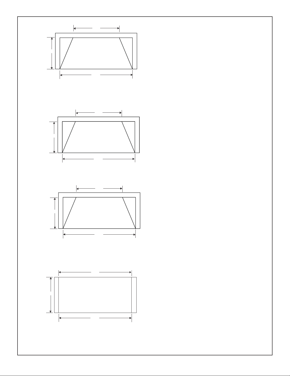
Gas Log Sets are Decorative Gas Appliances for Installation in a Solid-fuel Burning Fireplace. Minimum fi replace
sizes for these models is shown in Figure 1.
This log set is to be installed only in a solid-fuel burning fi replace with a working fl ue and one constructed of
noncombustible material. The minimum permanent vent
4
Heat & Glo • CFL-18/24/30-C, CFL-24-IPI, ST-CFL-24-B • 526-910 Rev. E • 10/08
B. High Altitude Installation
U.L. Listed gas appliances are tested and approved
without requiring changes for elevations from 0 to 2,000
feet in the U. S. A. and in Canada.
When installing this appliance at an elevation above
2,000 feet, it may be necessary to decrease the input
rating by changing the existing burner orifi ce to a smaller
size. Input rate should be reduced by 4% for each 1000
feet above a 2000 foot elevation in the U.S.A. or 10% for
elevations between 2000 and 4500 feet in Canada. If the
heating value of the gas has been reduced, these rules
do not apply . To identify the proper orifi ce size, check with
the local gas utility.
If installing this appliance at an elevation above 4,500 feet
(in Canada), check with local authorities.
Page 5
13 1/2
15 1/2
19 1/2
TOP VIEW
23 1/2
22
TOP VIEW
27 1/2
MODEL CFL-18-C
MINIMUM FIREPLACE SIZE
FRONT WIDTH : 23 1/2” (750mm)
REAR WIDTH : 19
1/2” (521mm)
DEPTH : 13 1/2” (331mm)
HEIGHT : 22” (508mm)
MINIMUM FIREPLACE SIZE
FRONT WIDTH : 27 1/2” (750mm)
REAR WIDTH : 22” (521mm)
DEPTH : 15 1/2” (331mm)
HEIGHT : 22” (508mm)
15 1/2
17
24
TOP VIEW
30
24
TOP VIEW
MODEL CFL-24-C
MODEL CFL-30-C
MINIMUM FIREPLACE SIZE
REAR WIDTH : 24” (521mm)
DEPTH : 17” (331mm)
HEIGHT : 20” (508mm)
MINIMUM FIREPLACE SIZE
FRONT WIDTH : 30” (750mm)
REAR WIDTH : 24” (521mm)
DEPTH : 15 1/2” (331mm)
HEIGHT : 22” (508mm)
FRONT WIDTH : 24” (521mm)
24
MODEL ST-CFL-24-B
Figure 1. Minimum Fireplace Sizes for CFL-18/24/30-C and ST-CFL-24-B
Heat & Glo • CFL-18/24/30-C, CFL-24-IPI, ST-CFL-24-B • 526-910 Rev. E • 10/08
5
Page 6
2
2
Getting Started
CAUTION
When installing this log set in a factory built fi replace, be
certain to consult the fi replace installation manual. ALL
knockouts in the fi replace through which the gas supply line
is run MUST be resealed with insulation after the gas line
is in place.
These models contain complete gas-burner, grate(s), and
log components needed. Use caution when handling logs
to avoid damage. Position the gas-burner assembly to the
rear of the fi replace. The ST-CFL-24 log set should be
positioned in the center of the unit. Once fully assembled,
the front log will extend forward of the burner assembly.
CAUTION
T o minimize the possibility of spillage and to maximize proper
draft, position the log set as close to the back of the fi replace
as possible. The ST-CFL-24 log set should be positioned in
the center of the unit.
A. Installation
1. Run proper size gas line into fi replace. A 1/2 inch
(13mm) gas line, with a 3/8 inch (10mm) reduction for
hook-up, is usually suffi cient for the Gas Log set; how-
ever, if the run is unusually long, a larger line may be required. Contact your local gas company or Department
of Building and Safety if there are any questions.
2. Minimum inlet gas supply pressure for purposes of input adjustment, shall be 7.0 inches w.c. (1.75kPa) for
natural gas and 1 1.0 inches w .c. (2.75kPa) for propane
(LP gas). Maximum inlet gas supply pressure shall be
14.0 in. w.c. (3.5kPa) for both natural gas and propane
(LP gas). Manifold (outlet) pressure should be 3.5
inches w.c. (.87kPa) for natural gas and 10.0 inches
w.c. (2.5kPa) for LP gas.
3. The appliance and its individual shut off valve must be
disconnected from the gas supply piping system during
any pressure testing of the system at test pressures in
excess of 1/2 psig (3.5kPa).
4. This appliance must be isolated from the gas supply
piping system by closing its individual manual shut off
valve during any pressure testing of the gas supply
piping system at test pressures equal to or less than
1/2 psig (3.5kPa).
Note: The gas supply line should be purged of any trapped
air prior to the fi rst fi ring of the unit.
CAUTION
Standing Pilot units only: During the initial purging and
subsequent lightings, NEVER allow the gas control valve knob
to remain depressed in the "PILOT" position without pushing
the ignitor button at least once every second.
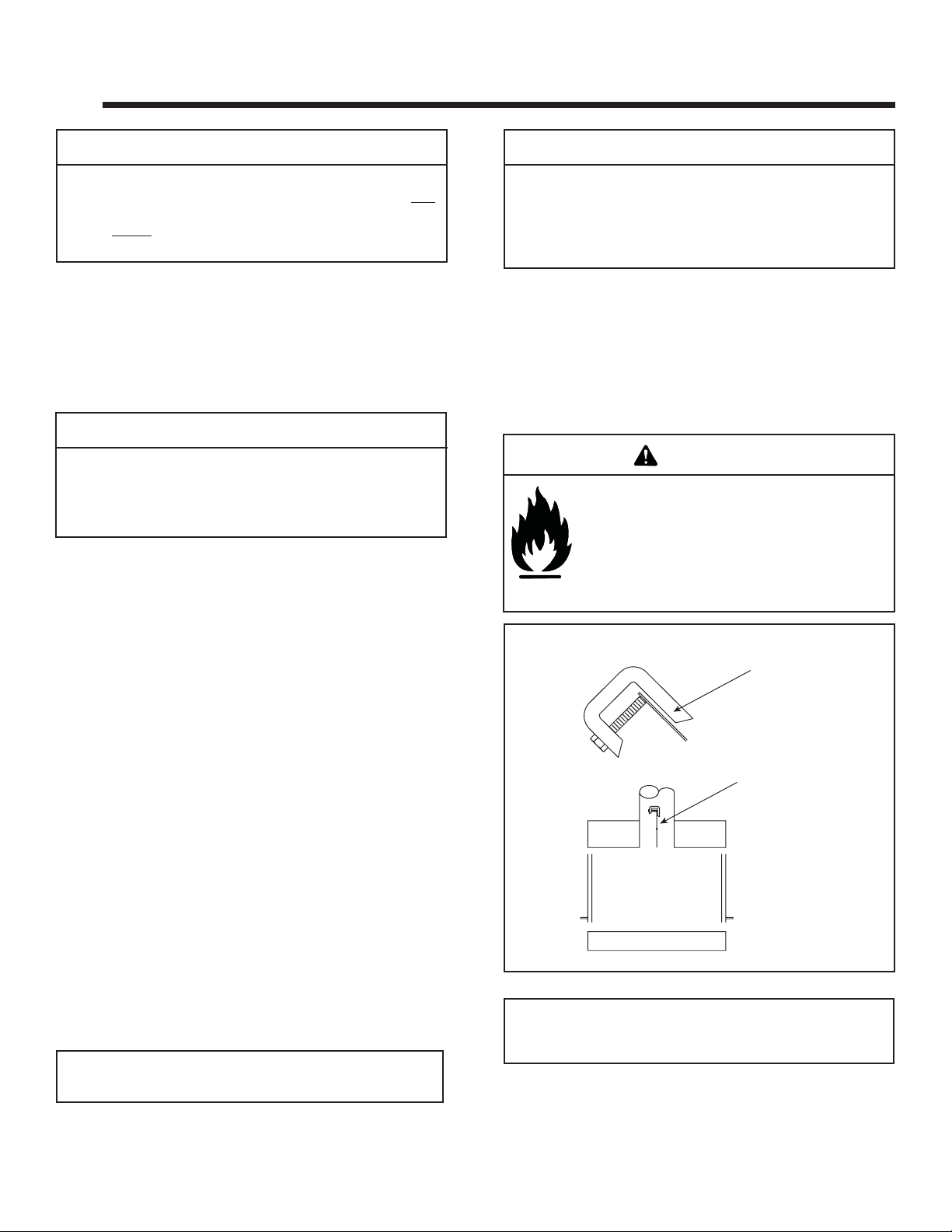
5. A damper stop clamp with set screw is provided to
prevent full closure of the fi replace damper blade. Attach
the clamp to the edge of the damper blade with pliers or
wrenches. If the damper stop supplied does not fi t the
application, use a permanent means that will keep the
damper open to a MINIMUM of 51 square inches (328cm2).
See Figure 2.
WARNING
Fire Risk
• Open the chimney damper to its FULLY
OPEN position when burning this gas log set.
• Logs must NEVER be burned without the fl ue
damper in the FULL OPEN position. Failure
to do so is dangerous to your health and
voids all warranties.
DAMPER CLAMP
OPEN DAMPER
Figure 2.
Note: The Commonwealth of Massachusetts requires that
the chimney fl ue damper, when used with gas logs, shall be
welded open or completely removed.
6
Heat & Glo • CFL-18/24/30-C, CFL-24-IPI, ST-CFL-24-B • 526-910 Rev. E • 10/08
Page 7
7. Test fi re the unit after referring to the SAFETY INFOR-
MATION and LIGHTING INSTRUCTIONS found in
Section 3 in this manual, or on the label plate assembly
found on the gas-burner.
8. After the gas line installation is complete, all connections
must be tightened and checked for leaks with a commercially-available, non-corrosive leak check solution.
Be sure to rinse off all leak check solution following
testing. Refer to Section 3, OPERA TING GUIDELINES
and MAINTENANCE INSTRUCTIONS.
9. Once the gas-burner is test fi red and gas supply lines
are purged, assemble the grate(s) and logs. Be certain
to follow the Log Placement Instructions shipped with
the unit. Remember to keep the Log Instructions along
with this manual for future use.
• This appliance may be used with a wall switch and/or
remote control.
• Use low resistance thermostat wire for wiring from ignition system to the wall switch.
• Keep wire lengths as short as possible by removing any
excess wire length.
• Low voltage and 110 VAC voltage cannot be shared
within the same wall box.
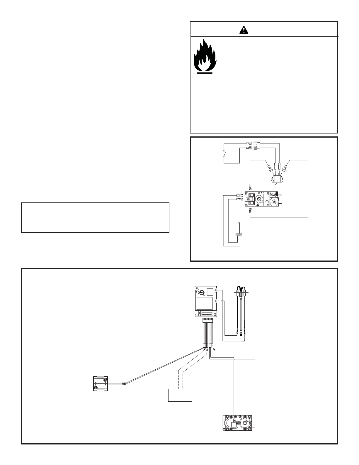
WARNING
Hearth & Home Technologies disclaims any
responsibility for, and the warranty will be voided
by, the following actions:
• Installation and use of any damaged appliance
or vent system component.
• Modifi cation of the appliance.
• Installation other than as instructed by Hearth &
Home Technologies.
• Improper positionsing of the gas logs.
• Installation and/or use of any component part
not approved by Hearth & Home Technologies.
Any such action may cause a fi re hazard.
BLACK BLACK
REMOTE
OR WALL
SWITCH
ON/OFF
SWITCH
Note: This appliance must be electrically wired and grounded
in accordance with local codes or, in the absence of local
codes, with National Electric Code ANSI/NFPA 70-latest
edition or the Canadian Electric Code, CSA C221.1.
BATTERY PACK
(BATTERIES REQUIRED)
RED
THERMOPILE
WHITE
Figure 4.
IGNITION MODULE 3 VAC INTERMITTENT PILOT IGNITOR
I
S
WHITE
ORANGE
GROUND TO
FIREPLACE
CHASSIS
RED
BLACK
WIRES
(TO BROWN)
Figure 3. IPI Wiring Diagram-CFL-24NG-IPI and CFL-24LP-IPI
Heat & Glo • CFL-18/24/30-C, CFL-24-IPI, ST-CFL-24-B • 526-910 Rev. E • 10/08
REMOTE OR
WALL SWITCH
ORANGE
VALVE
GREEN
7
Page 8
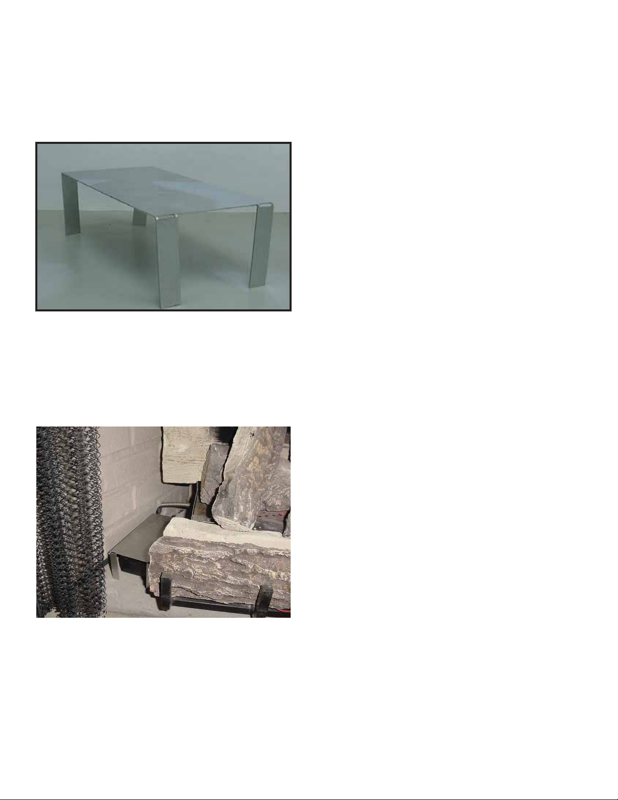
• If a remote control is used, the receiver cannot
be placed under the burner. If possible, place the
receiver outside the combustion chamber.
• If the receiver must be placed in the combustion
chamber, the protective heat shield MUST be used.
See Figure 5.
Figure 5. Protective Heat Shield
• Position receiver on left side of gas log set (opposite
the pilot). Place protective heat shield over receiver.
See Figure 5.
Figure 6. Receiver Location-Left Side of Log Set
8
Heat & Glo • CFL-18/24/30-C, CFL-24-IPI, ST-CFL-24-B • 526-910 Rev. E • 10/08
Page 9

3
3
Operating Guidelines and Maintenance Instructions
A. Before Lighting Appliance
Before lighting this appliance determine if it has a Standing
Pilot or Intellifi re ignition system by viewing the wiring
system and gas valve. If this appliance has a red or black
ignitor button (see Figure 3 and Figure 4) this appliance
has a Standing Pilot ignition system. If there is no red or
black ignitor button, this appliance has an Intellifi re ignition
system.
WARNING
Fire Risk
Be sure fi replace screen or glass doors are in
place when burning fi replace logs. Unless other
provisions for combustion air are provided, the
screen or doors shall have an opening for introduction of combustion air. THIS GAS LOG SET
IS NOT DESIGNED TO OPERATE WITH AIR
TIGHT GLASS DOORS. Adequate combustion
and cooling air must be provided or the unit will
not function properly.
WARNING
Fire Risk
Explosion Risk
WARNING: To avoid possible injury, fi re and
explosion, please read and follow these precautions and all instructions on this appliance
before lighting the pilot. This appliance uses
L.P . (Propane) gas which is heavier than air and
will remain at fl oor level if there is a leak. Before
lighting, smell at fl oor level and/or use other
means (such as using a commercially-available,
non-corrosive leak check solution on all piping
and connections, using a gas detector, etc.) to
check for gas leaks. NOTE: L.P . (Propane) gas
can become odorless and CANNOT always be
detected by smell.
WARNING
HOT SURFACES!
Glass and other surfaces are hot during
operation AND cool down.
Hot glass will cause burns.
• Do not touch glass until it is cooled
• NEVER allow children to touch glass
• Keep children away
• CAREFULLY SUPERVISE children in same room as
fi replace.
• Alert children and adults to hazards of high temperatures.
High temperatures may ignite clothing or other
fl ammable materials.
• Keep clothing, furniture, draperies and other fl ammable
materials away.
This appliance has been supplied with an integral barrier
to prevent direct contact with the fi xed glass panel. Do
NOT operate the appliance with the barrier removed.
Contact your dealer or Hearth & Home Technologies if the
barrier is not present or help is needed to properly install one.
WARNING
Improper installation, adjustment, alteration, service or
maintenance can cause injury or property damage. Refer to
the owner’s information manual provided with this appliance.
For assistance or additional information consult a qualifi ed
installer, service agency or the gas supplier.
WARNING
Do NOT use this appliance if any part has been under water.
Immediately call a qualifi ed service technician to inspect the
appliance and to replace any part of the control system and
any gas control which has been under water.
Before operating this appliance have a qualifi ed tech-
nician:
• Remove all shipping materials.
• Review proper placement of logs, rockwool, lava rock,
and vermiculite.
• Check the wiring.
• Ensure that there are no gas leaks.
Upon completing the gas line connection, a small amount
of air will be in the lines. When fi rst lighting the pilot light,
it will take a few minutes for the lines to purge themselves
of this air. Once the purging is complete, the pilot and
burner will light and operate as indicated in the instruction manual. Subsequent lighting of the appliance will not
require such purging.
Heat & Glo • CFL-18/24/30-C, CFL-24-IPI, ST-CFL-24-B • 526-910 Rev. E • 10/08
B. Maintenance
Periodically remove the logs and examine the burner. If
dirty , clean with a soft brush. Also examine the area around
the burner air shutter and the pilot. Any dirt or lint in this
area should be removed. This will ensure long life and
trouble-free operation.
The appliance and venting system should be inspected
before initial use and inspected and cleaned at least annually by a qualifi ed fi eld service person.
9
Page 10

Lighting Instructions (IPI)
The IPI system must be operated with two D-cell batteries.
FOR YOUR SAFETY
READ BEFORE LIGHTING
WARNING: If you do not follow these instructions exactly, a fi re or explosion
may result causing property damage, personal injury or loss of life.
A. This appliance is equipped with an
intermittent pilot ignition (IPI) device
which automatically lights the burner. DO NOT try to light the burner by
hand.
B. BEFORE LIGHTING, smell all around
the appliance area for gas. Be sure to
smell next to the fl oor because some
gas is heavier than air and will settle
on the fl oor.
WHA T TO DO IF YOU SMELL GAS
• DO NOT try to light any appliance.
• DO NOT touch any electric switch; do
not use any phone in your building.
WARNING:
DO NOT CONNECT 110 VAC TO
THE CONTROL VALVE.
Improper installation, adjustment, alteration, service or maintenance can
cause injury or property damage. Refer to the owner’s information manual
provided with this appliance.
This appliance needs fresh air for
safe operation and must be installed
so there are provisions for adequate
combustion and ventilation air.
If not installed, operated, and maintained in accordance with the manufacturer’s instructions, this product
could expose you to substances in fuel
or fuel combustion which are known to
the State of California to cause cancer, birth defects, or other reproductive
harm.
Keep burner and control compartment
clean. See installation and operating
instructions accompanying appliance.
• Immediately call your gas supplier
from a neighbor’s phone. Follow the
gas supplier’s instructions.
• If you cannot reach your gas supplier, call the fi re department.
C. DO NOT use this appliance if any
part has been under water. Immediately call a qualifi ed service tech-
nician to inspect the appliance and
to replace any part of the control
system and any gas control which
has been under water.
CAUTION:
Hot while in operation. DO NOT touch.
Keep children, clothing, furniture, gasoline and other liquids having fl ammable
vapors away.
DO NOT operate the appliance with
fi xed glass assembly removed, cracked
or broken. Replacement of the fi xed
glass assembly should be done by a
licensed or qualifi ed service person.
NOT FOR USE
WITH SOLID FUEL
For use with natural gas and propane.
A conversion kit, as supplied by the
manufacturer, shall be used to convert
this appliance to the alternate fuel.
Also Certifi ed for Installation in a
Bedroom or a Bedsitting Room.
For assistance or additional information, consult a qualifi ed installer, ser-
vice agency or the gas supplier.
LIGHTING
INSTRUCTIONS
(IPI)
1. Turn off all electric power to the appliance.
2. This appliance is equipped with an ignition
device which automatically lights the burner.
DO NOT try to light the burner by hand.
GAS
VALVE
3. Wait fi ve (5) minutes to clear out any gas.
Then smell for gas, including near the fl oor. If
you smell gas, STOP! Follow “B” in the Safety
Information located on the left side of this label. If you do not smell gas, go to next step.
4. Turn on all electric power to the appliance.
5. To light the burner, fl ip the ON/OFF switch to
the “ON” position. (The ON/OFF switch may
include a wall switch if so equipped).
6. If the appliance will not operate, follow the instructions “To Turn Off Gas to Appliance” and
call your service technician or gas supplier.
TO TURN OFF
GAS TO APPLIANCE
1. Turn wall control or ON/OFF switch to “OFF”.
2. Turn off all electric power to the appliance if
service is to be performed.
593-913F
Hearth & Home Technologies fi replace, please refer to www.fi replaces.com.
For additional information on operating your
Final inspection by
Figure 7. IPI Lighting Instructions
10
Heat & Glo • CFL-18/24/30-C, CFL-24-IPI, ST-CFL-24-B • 526-910 Rev. E • 10/08
Page 11

Lighting Instructions (Standing Pilot)
FOR YOUR SAFETY
READ BEFORE LIGHTING
WARNING: If you do not follow these instructions
exact ly, a fi re or explosion may result causing proper ty
damage, personal injury or loss of life.
A. This appliance has a pilot which
must be lighted by hand. When
lighting the pilot, follow these instructions exactly.
B. BEFORE LIGHTING, smell all
around the appliance area for gas.
Be sure to smell next to the fl oor
because some gas is heavier than
air and will settle on the fl oor.
WHAT TO DO IF YOU SMELL GAS
• Do not try to light any appliance.
• Do not touch any electric switch; do
not use any phone in your building.
• Immediately call your gas supplier
from a neighbor’s phone. Follow the
gas supplier’s instructions.
WARNING:
• If you cannot reach your gas supplier, call the fi re department.
C. Use only your hand to push in or
turn the gas control knob. Never
use tools. If the knob will not push
in or turn by hand, don’t try to repair it, call a qualifi ed service tech-
nician. Force or attempted repair
may result in a fi re or explosion.
D. Do not use this appliance if any
part has been under water. Immediately call a qualifi ed service tech-
nician to inspect the appliance and
to replace any part of the control
system and any gas control which
has been under water.
CAUTION:
LIGHTING
INSTRUCTIONS
1. Turn off all electric power to the appliance.
2. Push in gas control knob
slightly and turn clockwise
to “OFF”.
NOTE: Knob cannot be turned from “PILOT” to “OFF”
unless knob is pushed in slightly. Do not force.
3. Wait fi ve (5) minutes to clear out any gas.
Then smell for gas, including near the fl oor. If
you smell gas, STOP! Follow “B” in the Safety
Information located on the left side of this label. If
you don’t smell gas, go to next step.
4. Find the pilot. The pilot is inside
combustion chamber next to the
main burner.
5. Turn knob on gas control counter clockwise
to “PILOT”.
6. Push in control knob all the way and hold in. Immediately depress red or black piezo button. It may
require several depressions of the red or black
piezo button until PILOT lights. If PILOT light does
not light after 10 seconds, return to step 3. Continue to
hold the control knob in for about one minute after the
pilot is lit. Release knob and it will pop back out. Pilot
should remain lit. If it goes out, repeat steps 3 through 6.
DO NOT CONNECT 110 VAC TO
THE CONTROL VALVE.
Improper installation, adjustment, alteration, service or maintenance can
cause injury or property damage. Refer to the owner’s information manual
provided with this appliance.
This appliance needs fresh air for
safe operation and must be installed
so there are provisions for adequate
combustion and ventilation air.
If not installed, operated, and maintained in accordance with the manufacturer’s instructions, this product
could expose you to substances in fuel
or fuel combustion which are known to
the State of California to cause cancer, birth defects, or other reproductive harm.
Keep burner and control compartment
clean. See installation and operating
instructions accompanying appliance.
For additional information on operating your
Hearth & Home Technologies fi replace, please refer to www.fi replaces.com.
Hot while in operation. Do not touch.
Keep children, clothing, furniture, gasoline and other liquids having fl ammable
vapors away.
Do not operate the appliance with
panel(s) removed, cracked or broken.
Replacement of the panel(s) should be
done by a licensed or qualifi ed service
person.
NOT FOR USE
WITH SOLID FUEL
For use with natural gas and propane.
A conversion kit, as supplied by the
manufacturer, shall be used to convert
this appliance to the alternate fuel.
Also Certifi ed for Installation in a
Bedroom or a Bedsitting Room.
For assistance or additional information, consult a qualifi ed installer, ser-
vice agency or the gas supplier.
• If knob does not pop up when released, stop and immediately call your service technician or gas supplier.
• If the pilot will not stay lit after several tries, turn
the gas control knob to “OFF” and call your service
technician or gas supplier.
7. Turn gas control knob counterclockwise to
“ON”.
8. To light Burner, fl ip the on/off switch to the “ON”
position, and close access grille.
9. Turn on all electric power to the appliance.
TO TURN OFF
GAS TO APPLIANCE
1. Turn off all electric power to the appliance if
service is to be performed.
2. Open control access panel.
3. Move switch to “OFF” position.
4. Push in gas control knob slightly and turn clock-
wise to OFF”. Do not force.
5. Close control access panel.
Final inspection by
Figure 8. Lighting Instructions
Heat & Glo • CFL-18/24/30-C, CFL-24-IPI, ST-CFL-24-B • 526-910 Rev. E • 10/08
11
Page 12

4
4
Troubleshooting
With proper installation, operation, and maintenance your gas appliance will provide years of trouble-free service. If you do
experience a problem, this troubleshooting guide will assist a qualifi ed service technician in the diagnosis of a problem and
the corrective action to be taken. This troubleshooting guide can only be used by a qualifi ed service technician. Contact
your dealer to arrange a service call by a qualifi ed service technician.
A. Standing Pilot Ignition System
Symptom Possible Causes Corrective Action
1. After repeated triggering
of the red or black piezo
ignitor button, the spark
ignitor will not light the
pilot.
2. The pilot will not stay lit
after carefully following
the lighting instructions.
3. The pilot is burning,
there is no burner
fl ame, the valve knob is
in the ON position, and
the ON/OFF switch is in
the ON position.
A. No gas or low gas pressure. Check the remote shut-off valves from the appliance. Usually, there
is a valve near the gas main. There can be more than one valve
between the appliance and the main.
B. No lp in tank. Check the LP (propane) tank. You may be out of fuel.
C. Ignitor. Check the spark at the electrode and pilot. If no spark and electrode
wire is properly connected, replace the ignitor. Verify that there is no
short in electrode wire.
D. Pilot or misaligned electrode
(spark at electrode).
A. Thermocouple. Check that the pilot fl ame impinges on the thermocouple. Adjust the
B. Improper gas inlet pressure. Natural gas should be 5-14 in. w.c. LP should be 10-14 in. w.c.
C. Valve. If the thermocouple is producing 8-16 millivolts, replace control valve.
A. On/off switch or wires. Check the ON/OFF switch and wires for proper connections. Place
B. Thermopile may not be gen-
erating suffi cient millivoltage.
Using match, light the pilot. If the pilot lights, turn off the pilot and
trigger the piezo ignitor button again. If the pilot lights, an improper
gas/air mixture caused the bad lighting and a longer purge period is
recommended. If the pilot will not light, ensure the gap at the elec-
trode and pilot is one-eighth in. to have a strong spark. If the gap is
OK, replace the pilot.
pilot for proper fl ame impingement.
Ensure that the thermocouple connection at the gas valve is fully
inserted and tight (hand tighten plus 1/4 turn).
Verify proper voltage output from the thermocouple to the valve.
Place one millivolt meter lead wire on the thermocouple copper lead.
Place the second lead wire on the solder button on the back of the
valve (blue wire). Start the pilot and hold the valve knob in. The
millivolt reading should read 8-16 millivolts. If millivolt reading is
less than 8 millivolts, replace thermocouple.
Verify pressure with manometer.
the jumper wires across the terminals at the switch. If the burner
comes on, replace the switch. If the switch is OK, place the jumper
wires across the switch wires at the gas valve. If the burner comes
on, the wires are faulty or connections are bad.
Check that the pilot fl ame impinges thermopile properly.
Be sure the wire connections from the thermopile at the gas valve
terminals are tight and that the thermopile is fully inserted into the
pilot bracket.
Check the thermopile with a millivolt meter. Take the reading at
TH-TP&TP terminals of the gas valve. The meter should read 350
millivolts minimum, while holding the valve knob depressed in the
pilot position, with the pilot lit, and the ON/OFF switch in the OFF
position. Replace the thermopile if the reading is below the specifi ed
minimum.
With the pilot in the ON position, disconnect the thermopile leads
from the valve. Take a reading at the thermopile leads. The read-
ing should be 350 millivolts minimum. Replace the thermopile if the
reading is below the minimum.
12
Heat & Glo • CFL-18/24/30-C, CFL-24-IPI, ST-CFL-24-B • 526-910 Rev. E • 10/08
Page 13

Troubleshooting (continued)
Symptom Possible Cause Corrective Action
3. (Continued) c. Valve. Turn the valve knob to the ON position. Place the
ON/OFF switch in the ON position. Check the millivolt
meter a the thermopile terminals. The millivolt meter
should read greater than 125mV. If the reading is acceptable, and if the burner does not come on, replace
the gas valve.
d. Plugged burner orifi ce. Check the burner orifi ce for stoppage. Remove stop-
page.
e. Wall switch or wires. Follow the corrective action in Symptom and Possible
Cause 1.a above. Check the switch and wiring.
4. Frequent pilot outage
problem.
5. The pilot and main
burner extinguish
while in operation.
6. Glass soots. a. Flame impingement. Adjust the log set so that the fl ame does not exces-
a. Pilot fl ame may be too high or too low, or blow-
ing out (high pressure), causing pilot safety to
drop out.
a. No LP in tank. Check the LP (propane) tank. Refi ll the fuel tank.
b. Improper gas inlet pressure. Verify with manometer. NG should read 5-14 in. w.c.
c. Inner vent pipe leaking exhaust gases back into
the system.
d. Glass installed improperly. Check to ensure glass is installed properly. Replace
e. Thermopile or thermocouple. Replace pilot if necessary.
f. Improper vent cap installation. Check for proper installation and freedom from debris
b. Improper air shutter setting. Refer to manual for shutter set points. Ensure that
c. Debris around air shutter. Inspect the opening at the base of the burner. NO MA-
Clean thermocouple and adjust the pilot fl ame for
proper fl ame impingement. Follow lighting instructions
carefully.
LP should read 10-14 in. w.c.
Check venting system for damage. Replace/repair
improperly assembled pipe sections.
glass panel assembly.
or blockage.
sively impinge on it. Refer to log instructions.
set point is correct for appliance/gas type. If unit has
adjustable shutter, it may be necessary to increase
shutter opening.
TERIAL SHOULD BE PLACED IN THIS OPENING.
7. Flame burns blue
and lifts off burner.
a. Insuffi cient oxygen being supplied. Ensure that the vent cap is installed properly and free
of debris. Ensure that the vent system joints are tight
and have no leaks.
Ensure that no debris has been placed at the base of,
or in the area of the air holes in the center of the base
pan beneath the burner.
Ensure that the glass is tightened properly on the unit,
particularly on top corners.
Heat & Glo • CFL-18/24/30-C, CFL-24-IPI, ST-CFL-24-B • 526-910 Rev. E • 10/08
13
Page 14

B. Intellifi re Ignition System
Symptom Possible Cause Corrective Action
1. Pilot won’t light.
The ignitor/module
makes noise, but no
spark.
2. Pilot won’t light,
there is no noise or
spark.
a. Incorrect wiring. Verify “S” wire (white) for sensor and “I” wire (orange) for ignitor
are connected to correct terminals on module and pilot assembly.
b. Loose connections or electrical
shorts in the wiring.
c. Ignitor gap is too large. Verify gap of igniter to right side of pilot hood. The gap should be
d. Module. Turn ON/OFF rocker switch or wall switch to OFF position. Remove
a. No power. Check batteries.
b. A shorted or loose connection in
wiring confi guration or wiring har-
ness.
Verify no loose connections or electrical shorts in wiring from
module to pilot assembly. Verify connections underneath pilot assembly are tight; also verify connections are not grounding out to
metal chassis, pilot burner, pilot enclosure, mesh screen if present,
or any other metal object.
approximately .17 in. or 1/8 in. (3 mm).
ignitor wire “I” from module. Place a grounded wire about 3/16 in. (5
mm) away from “I” terminal on module. Place ON/OFF rocker switch
or wall switch in ON position. If there is no spark at “I” terminal
module must be replaced. If there is a spark at “I” terminal, module
is fi ne. Inspect pilot assembly for shorted sparker wire or cracked
insulator around electrode. Replace pilot if necessary .
Remove and reinstall the wiring harness that plugs into module.
Verify there is a tight fi t. Verify pilot assembly wiring to module. Re-
move and verify continuity of each wire in wiring harness. Replace
any damaged components.
3. Pilot sparks, but
Pilot will not light.
c. Improper wall switch wiring. Check wiring connections.
d. Module not grounded. Verify black ground wire from module wire harness is grounded to
metal chassis of appliance.
e. Module. Turn ON/OFF rocker switch or wall switch to OFF position. Re-
move ignitor wire “I” from module. Place ON/OFF rocker switch
or wall switch in ON position. If there is no spark at “I” terminal
module must be replaced. If there is a spark at “I” terminal, module
is fi ne. Inspect pilot assembly for shorted sparker wire or cracked
insulator around electrode.
a. Gas supply. Verify that incoming gas line ball valve is “open”. Verify that inlet
pressure reading is within acceptable limits, inlet pressure must
not exceed 14 in. W.C.
b. Ignitor gap is incorrect. Verify that spark gap from ignitor to pilot hood is .17 in. or 1/8 in (3 mm).
c. Module is not grounded. Verify module is securely grounded to metal chassis of appliance.
d. Module voltage output / Valve/Pilot
solenoid ohms readings.
Verify battery voltage is at least 2.7 volts. Replace batteries if volt-
age is below 2.7.
14
Heat & Glo • CFL-18/24/30-C, CFL-24-IPI, ST-CFL-24-B • 526-910 Rev. E • 10/08
Page 15

Intellifi re Ignition System - (continued)
Symptom Possible Cause Corrective Action
4. Pilot lights but continues to spark, and main
burner will not ignite.
(If the pilot continues
to spark after the
pilot fl ame has been lit,
fl ame rectifi cation has
not occurred.)
a. A shorted or loose connection in fl ame
sensing rod.
b. Poor fl ame rectifi cation or contaminated
fl ame sensing rod.
c. Module is not grounded. Verify module is securely grounded to metal chassis of
d. Damaged pilot assembly or contami-
nated fl ame sensing rod.
e. Module. Turn ON/OFF rocker switch or wall switch to OFF position.
Verify all connections to wiring diagram in manual. Verify
connections underneath pilot assembly are tight. Verify
connections are not grounding out to metal chassis, pilot
burner, pilot enclosure or screen if present, or any other
metal object.
With fi xed glass assembly in place, verify that fl ame is en-
gulfi ng fl ame sensing rod on left side of pilot hood. Flame
sensing rod
rect pilot orifi ce is installed and gas inlet is set to pressure
specifi cations. Clean fl ame sensing rod with emery cloth to
remove any contaminants that may have accumulated on
fl ame sensing rod.
appliance. Verify that wire harness is fi rmly connected to
the module.
Verify that ceramic insulator around the fl ame sensing
rod is not cracked, damaged, or loose. Verify connection
from fl ame sensing rod to white sensor wire. Clean fl ame
sensing rod with emery cloth to remove any contaminants
that may have accumulated on fl ame sensing rod. Verify
continuity with a multimeter with ohms set at lowest range.
Replace pilot if any damage is detected.
Remove ignitor wire “I” from module. Place ON/OFF rocker
switch or wall switch in ON position. If there is no spark at
“I” terminal module must be replaced. If there is a spark at
“I” terminal, module is fi ne.
should glow shortly after ignition. Verify cor-
Heat & Glo • CFL-18/24/30-C, CFL-24-IPI, ST-CFL-24-B • 526-910 Rev. E • 10/08
15
Page 16

5
5
Reference Materials
13
12
A. Service Parts
Service Parts Diagram
11
CFL-18NG-C, CFL-18LP-C
Beginning Manufacturing Date: Nov. 2007
Ending Manufacturing Date: ______
14
15
Log Set Assembly
10
8
6
1
3
17
16
5
9
7
2
4
Part number list on following page.
16
Heat & Glo • CFL-18/24/30-C, CFL-24-IPI, ST-CFL-24-B • 526-910 Rev. E • 10/08
Page 17

Service Parts List
IMPORTANT: THIS IS DATED INFORMATION. When requesting service or replacement
parts for your appliance please provide model number and serial number. All parts listed
in this manual may be ordered from an authorized dealer.
ITEM DESCRIPTION COMMENTS PART NUMBER
1 Log 1
2 Log 2
3 Log 3
4 Log 4
5 Log 5
6
Log 6
7 Log 7
8
Log 8
9 Log 9
10
1 1 Burner Assembly
12 Flexible Gas Connector
13 Grate Assembly
14
15 ON/Off Switch 060-521A
16 Flex Ball Valve Assembly
17
Log 10
Valve NG 418-500
Valve LP 418-501
Pilot Assembly NG 2103-010
Pilot Assembly LP 2103-011
Thermocouple 2103-511
Thermopile 2103-512
Pilot Orifi ce NG 2103-1 16
Pilot Orifi ce LP 2103-1 17
CFL-18NG-C, CFL-18LP-C
SRV481-766
SRV481-755
SRV481-701
SRV481-705
SRV446-702
SRV481-703
SRV402-701
SRV446-706
526-010A
477-301A
526-360
302-320A
Stocked
at Depot
Y
Y
Y
Y
Y
Y
Y
Y
Y
Y
Y
Y
Mineral Wool
Orifi ce NG (1.55) 526-801
Orifi ce LP (2.30 mm)
Piezo Ignitor
Remote Heat Shield
Vermiculite
Wire Assembly 24 in 089-550A
Heat & Glo • CFL-18/24/30-C, CFL-24-IPI, ST-CFL-24-B • 526-910 Rev. E • 10/08
050-721
526-800 Y
291-513
526-199
060-720
Y
Y
Y
17
Page 18

Service Parts
CFL-24NG-IPI, CFL-24LP-IPI
13
12
Service Parts Diagram
11
Beginning Manufacturing Date: June 2008
Ending Manufacturing Date: ______
14
15
16
Log Set Assembly
10
8
6
18
17
5
9
7
Part number list on following page.
18
Heat & Glo • CFL-18/24/30-C, CFL-24-IPI, ST-CFL-24-B • 526-910 Rev. E • 10/08
1
2
3
4
Page 19

Service Parts List
IMPORTANT: THIS IS DATED INFORMATION. When requesting service or replacement
parts for your appliance please provide model number and serial number. All parts listed
in this manual may be ordered from an authorized dealer.
ITEM DESCRIPTION COMMENTS PART NUMBER
1 Log 1
2 Log 2
3 Log 3
4 Log 4
5 Log 5
6
Log 6
7 Log 7
8
Log 8
9 Log 9
10
1 1 Burner Assembly
12 Flexible Gas Connector
13 Grate Assembly
14
15 Control Module 593-592 Y
16 ON/Off Switch 060-521A Y
17 Flex Ball Valve Assembly
18
Log 10
Valve NG 593-500 Y
Valve LP 593-501 Y
Pilot Assembly NG 2090-012 Y
Pilot Assembly LP 2090-013 Y
Pilot Orifi ce NG 593-528 Y
Pilot Orifi ce LP 593-527 Y
CFL-24NG-IPI, CFL-24LP-IPI
SRV481-766
SRV481-755
SRV526-701
SRV481-705
SRV446-702
SRV481-703
SRV402-701
SRV446-706
526-010A Y
477-301A Y
526-360
302-320A Y
Stocked
at Depot
Battery Pack 593-594A Y
Mineral Wool
Module Heat Shield
Orifi ce NG (1.55) 526-801 Y
Orifi ce LP (2.30 mm)
Remote Heat Shield
Vermiculite
Wire Assembly
Heat & Glo • CFL-18/24/30-C, CFL-24-IPI, ST-CFL-24-B • 526-910 Rev. E • 10/08
050-721
526-198
526-800
526-199
060-720
593-590A Y
Y
19
Page 20

Service Parts
CFL-24NG-C, CFL-24LP-C
13
12
Service Parts Diagram
11
Beginning Manufacturing Date: Nov. 2007
Ending Manufacturing Date: ______
14
15
Log Set Assembly
10
8
6
1
2
3
4
17
16
5
9
7
Part number list on following page.
20
Heat & Glo • CFL-18/24/30-C, CFL-24-IPI, ST-CFL-24-B • 526-910 Rev. E • 10/08
Page 21

Service Parts List
IMPORTANT: THIS IS DATED INFORMATION. When requesting service or replacement
parts for your appliance please provide model number and serial number. All parts listed
in this manual may be ordered from an authorized dealer.
ITEM DESCRIPTION COMMENTS PART NUMBER
1 Log 1
2 Log 2
3 Log 3
4 Log 4
5 Log 5
6
Log 6
7 Log 7
8
Log 8
9 Log 9
10
1 1 Burner Assembly
12 Flexible Gas Connector
13 Grate Assembly
14
15 ON/Off Switch 060-521A Y
16 Flex Ball Valve Assembly
17
Log 10
Valve NG 418-500 Y
Valve LP 418-501 Y
Pilot Assembly NG 2103-010 Y
Pilot Assembly LP 2103-011 Y
Thermocouple 2103-511 Y
Thermopile 2103-512 Y
Pilot Orifi ce NG 2103-1 16 Y
Pilot Orifi ce LP 2103-1 17 Y
CFL-24NG-C, CFL-24LP-C
SRV481-766
SRV481-755
SRV526-701
SRV481-705
SRV446-702
SRV481-703
SRV402-701
SRV446-706
526-010A Y
477-301A Y
526-360
302-320A Y
Stocked
at Depot
Mineral Wool
Orifi ce NG (1.55) 526-801 Y
Orifi ce LP (2.30 mm)
Piezo Ignitor
Remote Heat Shield
Vermiculite
Wire Assembly 24 in 089-550A Y
Heat & Glo • CFL-18/24/30-C, CFL-24-IPI, ST-CFL-24-B • 526-910 Rev. E • 10/08
050-721
526-800
291-513 Y
526-199
060-720
Y
21
Page 22

Service Parts
CFL-30NG-C, CFL-30LP-C
13
12
Service Parts Diagram
11
Beginning Manufacturing Date: Nov. 2007
Ending Manufacturing Date: ______
14
15
Log Set Assembly
10
8
6
1
3
17
16
5
9
11
7
2
4
Part number list on following page.
22
Heat & Glo • CFL-18/24/30-C, CFL-24-IPI, ST-CFL-24-B • 526-910 Rev. E • 10/08
Page 23

Service Parts List
IMPORTANT: THIS IS DATED INFORMATION. When requesting service or replacement
parts for your appliance please provide model number and serial number. All parts listed
in this manual may be ordered from an authorized dealer.
ITEM DESCRIPTION COMMENTS PART NUMBER
1 Log 1
2 Log 2
3 Log 3
4 Log 4
5 Log 5
6
Log 6
7 Log 7
8
Log 8
9 Log 9
10
11 Log 11
12
13 Flexible Gas Connector
14
15
16 ON/Off Switch 060-521A Y
17 Flex Ball Valve Assembly
18
Log 10
Burner Assembly
Grate Assembly
Valve NG 418-500 Y
Valve LP 418-501 Y
Pilot Assembly NG 2103-010 Y
Pilot Assembly LP 2103-011 Y
Thermocouple 2103-511 Y
Thermopile 2103-512 Y
Pilot Orifi ce NG 2103-1 16 Y
Pilot Orifi ce LP 2103-1 17 Y
CFL-30NG-C, CFL-30LP-C
SRV526-766
SRV526-755
SRV526-701
SRV481-705
SRV446-702
SRV481-704
SRV446-705
SRV446-706
SRV530-703
526-010A Y
477-301A Y
526-360
302-320A Y
Stocked
at Depot
Mineral Wool
Orifi ce NG (1.55) 526-801 Y
Orifi ce LP (2.30 mm)
Piezo Ignitor
Remote Heat Shield
Vermiculite
Wire Assembly 24 in 089-550A Y
Heat & Glo • CFL-18/24/30-C, CFL-24-IPI, ST-CFL-24-B • 526-910 Rev. E • 10/08
050-721
526-800
291-513 Y
526-199
060-720
Y
23
Page 24

Service Parts
ST -CFL-24NG-B, ST -CFL-24LP-B
15
Service Parts Diagram
14
Beginning Manufacturing Date: Nov. 2007
Ending Manufacturing Date: ______
16
17
20
18
19
Log Set Assembly
1
10
7
8
9
6
11
12
13
Part number list on following page.
24
Heat & Glo • CFL-18/24/30-C, CFL-24-IPI, ST-CFL-24-B • 526-910 Rev. E • 10/08
2
4
3
5
Page 25

Service Parts List
IMPORTANT: THIS IS DATED INFORMATION. When requesting service or replacement
parts for your appliance please provide model number and serial number. All parts listed
in this manual may be ordered from an authorized dealer.
ITEM DESCRIPTION COMMENTS PART NUMBER
Log 1 SRV569-710
1
Log 2
2
Log 3
3
Log 4
4
Log 5
5
6 Log 6 SRV569-708
Log 7 SRV569-709
7
8 Log 8 SRV569-704
Log 9 SRV569-706
9
10 Log 10 SRV569-707
11
12 Log 12 SRV569-703
13
14 Burner Assembly 526-01 1A Y
15
16 Grate Assembly 526-360
17
18 ON/Off Switch 060-521A Y
19
20
Log 11 SRV569-702
Log 13 SRV569-705
Flexible Gas Connector 477-301A Y
Valve NG 418-500 Y
Valve LP 418-501 Y
Flex Ball Valve Assembly 302-320A Y
Pilot Assembly NG 2103-010 Y
Pilot Assembly LP 2103-011 Y
Thermocouple 2103-511 Y
Thermopile 2103-512 Y
Pilot Orifi ce NG 2103-1 16 Y
Pilot Orifi ce LP 2103-1 17 Y
ST -CFL-24NG-B, ST -CFL-24LP-B
SRV569-711
SRV482-755
Stocked
at Depot
Mineral Wool 050-721
Orifi ce NG (1.55) 526-801 Y
Orifi ce LP (2.30 mm)
Piezo Ignitor 291-513 Y
Remote Heat Shield 526-199
Vermiculite 060-720
Wire Assembly 24 in 089-550A Y
Heat & Glo • CFL-18/24/30-C, CFL-24-IPI, ST-CFL-24-B • 526-910 Rev. E • 10/08
526-800
Y
25
Page 26

B. Limited Lifetime Warranty
Hearth & Home Technologies LIMITED WARRANTY
Hearth & Home Technologies (“HHT”) and its respective brands extends the following warranty for HHT gas, wood, pellet
and electric appliances purchased from an authorized HHT dealer and installed in the United States of America or Canada.
Warranty starts with date of purchase by the original owner (End User) except as noted for replacement parts.
Warranty Period HHT Manufactured Appliances and Venting
Parts Labor Gas Wood Pellet
1 Year XXXXXX
EPA
Wood
Electric Venting
Components Covered
All Parts and Material Except as
covered by Conditions, Exclusion,
and Limitations listed
XX
2 years
3 years X Firepots
5 years 3 years X X Castings & Baffl es
7 years 3 years X X X
10 years 1 year X Burners, Logs & Refractory
Limited
Lifetime
1 year X Firebox & Heat Exchanger
90 Days XXXXXX All Replacement Parts
XXXX Blowers
X Molded Refractory Panels
Igniters, Electronic Components,
and Glass
Firebox, HHT Chimney,
Termination & Heat
Exchanger
See Conditions, Exclusions, and limitations. 9-01-08
CONDITIONS, EXCLUSIONS & LIMITATION OF LIABILITY
• This warranty applies to the original owner and is transferable up to two years from date of purchase to the new homeowner,
provided the purchase was made through an authorized dealer or distributor of HHT, and the appliance remains in its
original place of installation.
• The maximum amount recoverable under this warranty is limited to the purchase price of the product.
• In no event shall HHT be liable for any incidental or consequential damages caused by defects in the product.
• Adjustments, regular maintenance, cleaning and temporary repairs, or the failure to duplicate the problem in the home is
not covered under this warranty.
Page 1 of 2 4021-645A 09-01-08
26
Heat & Glo • CFL-18/24/30-C, CFL-24-IPI, ST-CFL-24-B • 526-910 Rev. E • 10/08
Page 27

B. Limited Lifetime Warranty (continued)
• This limited warranty does not extend to or include surface fi nish on the appliance or terminations, door gasketing, glass
gasketing, glass discoloration, fi rebrick, pellet logs, kaowool or other ceramic insulating materials. Rust and/or corrosion
on any of the metal surfaces, cast iron components, baffl es, fi repots, doors, or fi rebox area are not covered by this
warranty.
• Noise resulting from minor expansion, contraction, or movement of certain parts is normal and complaints related to this
noise are not covered by this warranty.
• HHT’s obligation under this warranty does not extend to damages resulting from: (1) installation, operation or maintenance
of the appliance not in accordance with the installation instructions; operating instructions and the listing agent identifi cation
label furnished with the appliance; (2) installation which does not comply with local building codes; (3) shipping, improper
handling, improper operation, abuse, misuse, accident or unworkmanlike repairs; (4) environmental conditions, inadequate
ventilation or drafting caused by tight sealing construction of the structure or handling devices such as exhaust fans or forced
air furnaces or other such causes; (5) use of fuels other than those specifi ed in the operating instructions; (6) installation
or use of components not supplied with the appliance or any other components not expressly authorized and approved
by HHT; and/or (7) modifi cation of the appliance not expressly authorized and approved by HHT in writing.
• This warranty does not apply to non-HHT venting components, hearth components or other accessories used in conjunction
with the installation of this product.
• This warranty is void if the appliance has been over-fi red or operated in atmospheres contaminated by chlorine, fl uorine,
or other damaging chemicals the appliance is subject to prolonged periods of dampness or condensation, or there is any
damage to the appliance or other components due to water or weather damage which is the result of, but not limited to,
improper chimney or venting installation.
• HHT’s liability under this warranty is limited to the replacement and repair of defective components or workmanship during
the applicable period. HHT may fully discharge all of its obligations under such warranties by repairing the defective
component(s) at HHT’s discretion. Shipping costs are not covered under this warranty.
• Some states do not allow exclusions or limitation of incidental or consequential damages, so those limitations may not
apply to you. This warranty gives you specifi c rights; you may also have other rights, which vary from state to state.
• EXCEPT TO THE EXTENT PROVIDED BY LAW, HHT MAKES NO EXPRESS WARRANTIES OTHER THAN THE
WARRANTY SPECIFIED HEREIN. THE DURATION OF ANY IMPLIED WARRANTY IS LIMITED TO DURATION OF
THE WARRANTY SPECIFIED ABOVE.
This Limited Warranty is effective on all HHT appliances sold after September 01, 2008 and supersedes any and all
warranties currently in existence.
If warranty service is needed, you should contact your installing dealer. If the installing dealer is unable to provide necessary
parts or components, contact the nearest authorized HHT dealer or supplier.
Page 2 of 2 4021-645A 09-01-08
Heat & Glo • CFL-18/24/30-C, CFL-24-IPI, ST-CFL-24-B • 526-910 Rev. E • 10/08
27
Page 28

C. Contact Information
Heat & Glo, a brand of Hearth & Home Technologies Inc.
20802 Kensington Boulevard, Lakeville, MN 55044
www.heatnglo.com
Please contact your Heat & Glo dealer with any questions or concerns.
For the location of your nearest Heat & Glo dealer,
please visit www.heatnglo.com.
- NOTES -
________________________________________________________________________________
________________________________________________________________________________
________________________________________________________________________________
________________________________________________________________________________
________________________________________________________________________________
________________________________________________________________________________
________________________________________________________________________________
________________________________________________________________________________
________________________________________________________________________________
CAUTION
DO NOT DISCARD THIS MANUAL
• Important operating
and maintenance
instructions included.
• Read, understand and follow
these instructions for safe
installation and operation.
• Leave this manual with
party responsible for use
and operation.
This product may be covered by one or more of the following patents: (United States) 4593510, 4686807, 4766876, 4793322, 4811534, 5000162, 5016609, 5076254, 51 13843, 5191877, 5218953, 5263471,
5328356, 5341794, 5347983, 5429495, 5452708, 5542407, 5601073, 5613487, 5647340, 5688568, 5762062, 5775408, 5890485, 5931661, 5941237, 5947112, 5996575, 6006743, 6019099, 6048195,
6053165, 6145502, 6170481, 6237588, 6296474, 6374822, 6413079, 6439226, 6484712, 6543698, 6550687, 6601579, 6672860, 6688302B2, 6715724B2, 6729551, 6736133, 6748940, 6748942, 6769426,
6774802, 6796302, 6840261, 6848441, 6863064, 6866205, 6869278, 6875012, 6880275, 6908039, 6919884, D320652, D445174, D462436; (Canada) 1297749, 2195264, 2225408, 2313972; (Australia)
780250, 780403, 1418504 or other U.S. and foreign patents pending.
28
Heat & Glo • CFL-18/24/30-C, CFL-24-IPI, ST-CFL-24-B • 526-910 Rev. E • 10/08
Printed in U.S.A. - Copyright 2008
 Loading...