

Page 1
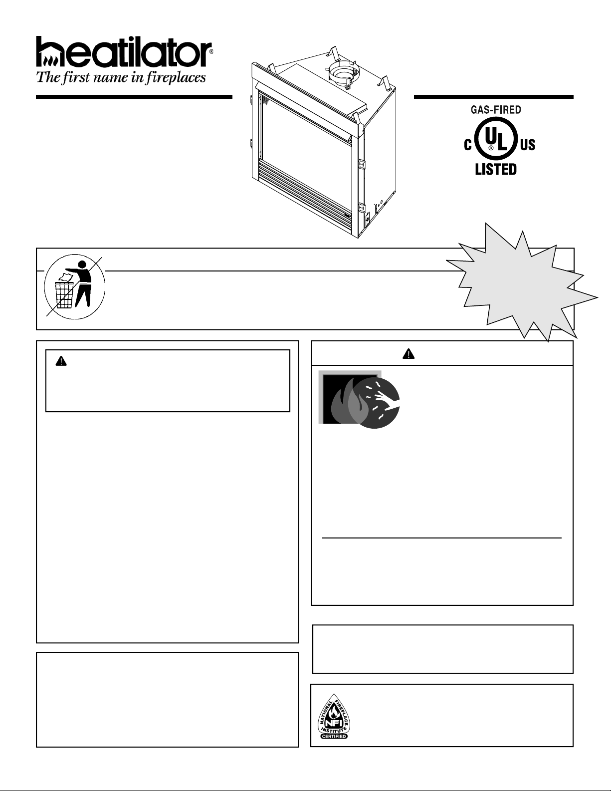
Model(s):
DO NOT
DISCARD
CB4236IR
CB4842IR
B-Vent Gas Appliance
Owner’s Manual
Installation and Operation
NOTICE
DO NOT DISCARD THIS MANUAL
• Important operating
and maintenance
instructions included.
WARNING: If the information in these
instructions is not followed exactly, a fi re
or explosion may result causing property
damage, personal injury, or death.
• DO NOT store or use gasoline or other fl am-
mable vapors and liquids in the vicinity of this
or any other appliance.
• What to do if you smell gas
- DO NOT try to light any appliance.
- DO NOT touch any electrical switch. DO
NOT use any phone in your building.
- Immediately call your gas supplier from a
neighbor’s phone. Follow the gas supplier’s instructions.
- If you cannot reach your gas supplier, call
the fi re department.
• Installation and service must be performed
by a qualifi ed installer, service agency, or the
gas supplier.
This appliance may be installed as an OEM installation
in manufactured home (USA only) or mobile home and
must be installed in accordance with the manufacturer’s
instructions and the manufactured home construction and
safety standard, Title 24 CFR, Part 3280 or Standard for
Installation in Mobile Homes, CAN/CSA Z240MH.
This appliance is only for use with the type(s) of gas
indicated on the rating plate.
• Read, understand and follow
these instructions for safe
installation and operation.
DO NOT
DISCARD
• Leave this manual with
party responsible for use
and operation.
WARNING
HOT SURFACES!
Glass and other surfaces are hot during
operation AND cool down.
Hot glass will cause burns.
• DO NOT touch glass until it is cooled
• NEVER allow children to touch glass
• Keep children away
• CAREFULLY SUPERVISE children in same room as
fi replace.
• Alert children and adults to hazards of high temperatures.
High temperatures may ignite clothing or other fl ammable
materials.
• Keep clothing, furniture, draperies and other fl ammable
materials away.
This appliance has been supplied with an integral barrier
to prevent direct contact with the fi xed glass panel. DO
NOT operate the appliance with the barrier removed.
Contact your dealer or Hearth & Home Technologies if the
barrier is not present or help is needed to properly install one.
In the Commonwealth of Massachusetts installation must be
performed by a licensed plumber or gas fi tter.
A CO detector shall be installed in the room where the appliance
in installed.
Installation and service of this appliance should be
performed by qualifi ed personnel. Hearth & Home
Technologies suggests NFI certifi ed or factory trained
professionals, or technicians supervised by an NFI
certifi ed professional.
Heatilator • Caliber BV Series • 4040-262 Rev J • 10/08 1
Page 2
Read this manual before installing or operating this appliance.
Please retain this owner’s manual for future reference.
A. Congratulations
Congratulations on selecting a Heatilator gas fi replace,
an elegant and clean alternative to wood burning fi re-
places. The Heatilator gas fi replace you have selected is
designed to provide the utmost in safety, reliability, and
effi ciency.
As the owner of a new fi replace, you’ll want to read and
carefully follow all of the instructions contained in this
owner’s manual. Pay special attention to all cautions and
warnings.
This owner’s manual should be retained for future reference.
We suggest that you keep it with your other important
documents and product manuals.
The information contained in this owner’s manual, unless
noted otherwise, applies to all models and gas control
systems.
Your new Heatilator gas fi replace will give you years of
durable use and trouble-free enjoyment. Welcome to the
Heatilator family of fi replace products!
Homeowner Reference Information
We recommend that you record the following pertinent
information about your fi replace.
Model Name: ___________________________________________ Date purchased/installed: __________________
Serial Number: __________________________________________ Location on fi replace: _____________________
Dealership purchased from: _______________________________ Dealer Phone: __________________________
Notes: _______________________________________________________________________________________
_____________________________________________________________________________________________
Listing Label Information/Location
The model information regarding your specifi c fi replace can be found on
the rating plate usually located in the control area of the fi replace.
Serial #
XXXXXXXXX
Model #
Hearth & Home Technologies Inc
1915 W. Saunders Street
Mt. Pleasant, IA 52641
ANSI Standard
Gas Type
SERIAL
NO. DE SÉRIE
MODEL MFG. DATE
MODÈLE DATE DE FAB.
GAS TYPE/TYPE DE GAZ NATURAL/NATUREL PROPANE
ALTITUDE 0-2000 2000-4000 FT/PI 0-2000 2000-4000 FT/PI
MAX INPUT/DÉBIT XX,XXX XX,XXX BTUH XX,XXX XX,XXX BTUH
MIN INPUT/DÉBIT XX,XXX XX,XXX BTUH XX,XXX XX,XXX BTUH
MANIFOLD PRESSURE/PRESSION TUBULAIRE
MAX. XX IN. W.C./C. D'EAU XX IN. W.C./C. D'EAU
MIN. XX IN. W.C./C. D'EAU XX IN. W.C./C. D'EAU
MIN. INLET PRESS. XX IN. W.C./C. D'EAU 1XX IN. W.C./C. D'EAU
FOR THE PURPOSE OF INPUT ADJUSTMENT
PRESS. MIN. D'ALIMENTATION
ORIFICE SIZE
DIAM. DE L'INJECTEUR XX/XX DIA. in./mm XX/XX DIA. in./mm
LESS THAN/MOINS DE 3 AMPÈRES., 115V., 60 Hz
DO NOT REMOVE OR COVER THIS LABEL.
VENTED GAS FIREPLACE - NOT FOR USE WITH SOLID FUEL.
FOYER À GAZ À ÉVACUATION - NE DOIT PAS ÊTRE UTILISÉ
AVEC UN COMBUSTIBLE SOLIDE.
XXXXXX
Heatilator • Caliber BV Series • 4040-262 Rev J • 10/082
XXXX
CERTIFIED
FOR CANADA
CERTIFIÉ POUR LE
CANADA
Orifice
Size
Page 3

Safety Alert Key:
• DANGER! Indicates a hazardous situation which, if not avoided will result in death or serious injury.
• WARNING! Indicates a hazardous situation which, if not avoided could result in death or serious injury.
• CAUTION! Indicates a hazardous situation which, if not avoided, could result in minor or moderate injury.
• NOTICE: Used to address practices not related to personal injury.
Table of Contents
A. Congratulations 2
B. Warranty 5
1 Listing and Code Approvals
A. Appliance Certifi cation 7
B. Tempered Glass Specifi cations 7
C. BTU Specifi cations 7
D. High Altitude Installations 7
E. Non-Combustible Materials Specifi cation 7
F. Combustible Materials Specifi cation 7
G. Electrical Codes 7
User Guide
2 Operating Instructions
A. Gas Fireplace Safety 8
B. Your Fireplace 8
C. Fan Kit (optional) 9
D. Clear Space 9
E. Decorative Doors and Fronts 9
F. Fixed Glass Assembly 9
G. Remote Controls, Wall Controls and Wall Switches 9
H. Outside Air (optional) 9
I. Before Lighting Fireplace 9
J. Lighting Instructions (IPI) 10
K. After Fireplace is Lit 11
L. Frequently Asked Questions 11
3 Maintenance and Service
A. Maintenance Tasks-Homeowner 12
B. Maintenance Tasks-Qualifi ed Service Technician 13
Installer Guide
4 Getting Started
A. Typical Appliance System 14
B. Design and Installation Considerations 15
C. Tools and Supplies Needed 15
D. Inspect Appliance and Components 15
E. Negative Pressure 16
5 Framing and Clearances
A. Selecting Appliance Location 17
B. Constructing the Appliance Chase 17
C. Clearances 18
D. Mantel and Wall Projections 19
6 Termination Locations
A. Vent Termination Minimum Clearances 20
7 Vent Information and Diagrams
A. Vent Guidelines 21
B. Vent System Confi guration 21
8 Vent Clearances and Framing
A. Pipe Clearances to Combustibles 22
B. Wall and Ceiling Penetration Framing 22
C. Vertical Penetration Framing 22
9 Appliance Preparation
A. Install Outside Air Kit Damper Assembly 23
B. Gas and Electrical Connections 23
C. Secure and Level the Appliance 23
10 Installing Vent Pipe
A. Assembly of Vent Sections 24
B. Attach Vent to Firebox 24
C. Secure Vent Sections 24
D. Install Attic Insulation Shield 24
11 Gas Information
A. Fuel Conversion 25
B. Gas Pressure 25
C. Gas Connection 25
D. High Altitude Installations 25
12 Electrical Information
A. Wiring Requirements 26
B. Intellifi re Ignition System Wiring 26
C. Optional Accessories Requirements 26
D. Electrical Service and Repair 26
E. Junction Box Installation 27
F. Wall Switch Installation for Fan (Optional) 27
13 Finishing
A. Mantel and Wall Projections 28
B. Facing Material 28
Heatilator • Caliber BV Series • 4040-262 Rev J • 10/08 3
Page 4

14 Appliance Setup
A. Remove Glass Assembly 29
B. Remove the Shipping Materials 29
C. Clean the Appliance 29
D. Accessories 29
E. Install the Refractory 29
F. Place the Lava Rock & Vermiculite 29
G. Place the Rockwool 29
H. Install the Log Assembly 30
I. Firescreen 30
J. Glass Assembly 30
K. Install Louvers and Trim 31
L. Hood 31
M. Air Shutter Setting 31
15 Troubleshooting
A. Intellifi re Ignition System 32
16 Reference Materials
A. Appliance Dimension Diagram 34
B. Service Parts List 35
C. Optional Components 38
D. Contact Information 40
= Contains updated information.
Heatilator • Caliber BV Series • 4040-262 Rev J • 10/084
Page 5
B. Warranty
Hearth & Home Technologies LIMITED WARRANTY
Hearth & Home Technologies (“HHT”) and its respective brands extends the following warranty for HHT gas, wood,
pellet and electric appliances purchased from an authorized HHT dealer and installed in the United States of America or
Canada. Warranty starts with date of purchase by the original owner (End User) except as noted for replacement parts.
Warranty Period HHT Manufactured Appliances and Venting
Parts Labor Gas Wood Pellet
1 Year XXXXXX
EPA
Wood
Electric Venting
Components Covered
All Parts and Material Except
as covered by Conditions,
Exclusion, and Limitations listed
XX
2 years
3 years X Firepots
5 years 3 years X X Castings & Baffl es
7 years 3 years X X X
10
years
Limited
Lifetime
1 year X Burners, Logs & Refractory
1 year X Firebox & Heat Exchanger
90 Days XXXXXX All Replacement Parts
XXXX Blowers
X Molded Refractory Panels
Igniters, Electronic
Components, and Glass
Firebox, HHT Chimney,
Termination & Heat
Exchanger
See Conditions, Exclusions, and limitations. 9-01-08
CONDITIONS, EXCLUSIONS & LIMITATION OF LIABILITY
This warranty applies to the original owner and is transferable up to two years from date of purchase to the new
homeowner, provided the purchase was made through an authorized dealer or distributor of HHT, and the appliance
remains in its original place of installation.
The maximum amount recoverable under this warranty is limited to the purchase price of the product.
In no event shall HHT be liable for any incidental or consequential damages caused by defects in the product.
Adjustments, regular maintenance, cleaning and temporary repairs, or the failure to duplicate the problem in the home
is not covered under this warranty.
4021-645A 09-01-08 Page 1 of 2
Heatilator • Caliber BV Series • 4040-262 Rev J • 10/08 5
Page 6

B. Warranty (continued)
This limited warranty does not extend to or include surface fi nish on the appliance or terminations, door gasketing, glass
gasketing, glass discoloration, fi rebrick, pellet logs, kaowool or other ceramic insulating materials. Rust and/or corrosion
on any of the metal surfaces, cast iron components, baffl es, fi repots, doors, or fi rebox area are not covered by this
warranty.
Noise resulting from minor expansion, contraction, or movement of certain parts is normal and complaints related to
this noise are not covered by this warranty.
HHT’s obligation under this warranty does not extend to damages resulting from: (1) installation, operation or
maintenance of the appliance not in accordance with the installation instructions; operating instructions and the
listing agent identifi cation label furnished with the appliance; (2) installation which does not comply with local building
codes; (3) shipping, improper handling, improper operation, abuse, misuse, accident or unworkmanlike repairs; (4)
environmental conditions, inadequate ventilation or drafting caused by tight sealing construction of the structure
or handling devices such as exhaust fans or forced air furnaces or other such causes; (5) use of fuels other than
those specifi ed in the operating instructions; (6) installation or use of components not supplied with the appliance or
any other components not expressly authorized and approved by HHT; and/or (7) modifi cation of the appliance not
expressly authorized and approved by HHT in writing.
This warranty does not apply to non-HHT venting components, hearth components or other accessories used in
conjunction with the installation of this product.
This warranty is void if the appliance has been over-fi red or operated in atmospheres contaminated by chlorine,
fl uorine, or other damaging chemicals the appliance is subject to prolonged periods of dampness or condensation, or
there is any damage to the appliance or other components due to water or weather damage which is the result of, but
not limited to, improper chimney or venting installation.
HHT’s liability under this warranty is limited to the replacement and repair of defective components or workmanship
during the applicable period. HHT may fully discharge all of its obligations under such warranties by repairing the
defective component(s) at HHT’s discretion. Shipping costs are not covered under this warranty.
Some states do not allow exclusions or limitation of incidental or consequential damages, so those limitations may not
apply to you. This warranty gives you specifi c rights; you may also have other rights, which vary from state to state.
EXCEPT TO THE EXTENT PROVIDED BY LAW, HHT MAKES NO EXPRESS WARRANTIES OTHER THAN THE
WARRANTY SPECIFIED HEREIN. THE DURATION OF ANY IMPLIED WARRANTY IS LIMITED TO DURATION OF
THE WARRANTY SPECIFIED ABOVE.
This Limited Warranty is effective on all HHT appliances sold after September 01, 2008 and supersedes any and all
warranties currently in existence.
If warranty service is needed, you should contact your installing dealer. If the installing dealer is unable to provide
necessary parts or components, contact the nearest authorized HHT dealer or supplier.
4021-645A 09-01-08 Page 2 of 2
Heatilator • Caliber BV Series • 4040-262 Rev J • 10/086
Page 7
1
1
Listing and Code Approvals
A. Appliance Certifi cation
MODELS: CB4236IR, CB4842IR
LABORATORY: Underwriters Laboratories, Inc. (UL)
TYPE: B-Vent Gas Appliance Heater
STANDARD: ANSI Z21.88-2005/CSA 2.33-2005
This product is listed to ANSI standards for “Vented Gas
Fireplace Heaters” and “Gas Fired Appliances for Use at
High Altitudes”.
This model may be installed in a sleeping room when the
provisions for combustion, ventilation and dilution air are
met per the requirements of ANSI 223.1/NFPA 54 Na-
tional Fuel Gas Code. In Canada, installation in a sleeping room requires installation with a thermostat certifi ed
for use with this product. Consult your local authorities
having jurisdiction.
NOTICE: This installation must conform with local codes.
In the absence of local codes you must comply with the
National Fuel Gas Code, ANSI Z223.1-latest edition in
the U.S.A. and the CAN/CGA B149 Installation Codes in
Canada.
C. BTU Specifi cations
Caliber BV Series CB4236 CB4842
IPI
Max/Min Input Rate (NG) 30,000/20,000 33,000/22,000
Orifi ce Size (NG) .101 in./2.56 mm .104 in./2.64 mm
Max/Min Input Rate (LP) 29,500/19,500 32,500/20,000
Orifi ce Size (LP) .0635 in./1.61 mm .065 in./1.65 mm
D. High Altitude Installations
NOTICE: If the heating value of the gas has been reduced,
these rules do not apply. Check with your local gas utility or
authorities having jurisdiction.
When installing above 2000 feet elevation:
• In the USA: Reduce input rate 4% for each 1000 feet
above 2000 feet.
• In CANADA: Reduce input rate 10% for elevations
between 2000 feet and 4500 feet. Above 4500 feet,
consult local gas utility.
Check with your local gas utility to determine proper
orifi ce size.
NOT INTENDED FOR USE AS A PRIMARY HEAT SOURCE.
This appliance is tested and approved as either supplemental
room heat or as a decorative appliance. It should not be factored as primary heat in residential heating calculations.
B. Tempered Glass Specifi cations
Hearth & Home Technologies appliances manufactured
with tempered glass may be installed in hazardous
locations such as bathtub enclosures as defi ned by the
Consumer Product Safety Commission (CPSC). The
tempered glass has been tested and certifi ed to the
requirements of ANSI Z97.1 and CPSC 16 CFR 1202
(Safety Glazing Certifi cation Council SGCC# 1595 and
1597. Architectural Testing, Inc. Reports 02-31919.01 and
02-31917.01).
This statement is in compliance with CPSC 16 CFR
Section 1201.5 “Certifi cation and labeling requirements”
which refers to 15 U.S. Code (USC) 2063 stating “…Such
certifi cate shall accompany the product or shall otherwise
be furnished to any distributor or retailer to whom the
product is delivered.”
Some local building codes require the use of tempered
glass with permanent marking in such locations. Glass
meeting this requirement is available from the factory.
Please contact your dealer or distributor to order.
E. Non-Combustible Materials Specifi cation
Material which will not ignite and burn. Such materials are
those consisting entirely of steel, iron, brick, tile, concrete,
slate, glass or plasters, or any combination thereof.
Materials that are reported as passing ASTM E 136, Standard Test Method for Behavior of Materials in a Vertical
Tube Furnace at 750 ºC and UL763 shall be considered
non-combustible materials.
F. Combustible Materials Specifi cation
Materials made of or surfaced with wood, compressed
paper, plant fi bers, plastics, or other material that can ig-
nite and burn, whether fl ame proofed or not, or plastered
or unplastered shall be considered combustible materials.
G. Electrical Codes
NOTICE: This appliance must be electrically wired
and grounded in accordance with local codes or, in the
absence of local codes, with National Electric Code
ANSI/NFPA 70-latest edition or the Canadian Electric
Code CSA C22.1.
• A 110-120 VAC circuit for this product must be protected
with ground-fault circuit-interrupter protection, in
compliance with the applicable electrical codes, when
it is installed in locations such as in bathrooms or near
sinks.
Heatilator • Caliber BV Series • 4040-262 Rev J • 10/08 7
Page 8
2
User Guide
2
A. Gas Fireplace Safety
Operating Instructions
WARNING
HOT SURFACES!
Glass and other surfaces are hot during
operation AND cool down.
Hot glass will cause burns.
• DO NOT touch glass until it is cooled
• NEVER allow children to touch glass
• Keep children away
• CAREFULLY SUPERVISE children in same room as
fi replace.
• Alert children and adults to hazards of high temperatures.
High temperatures may ignite clothing or other fl ammable
materials.
• Keep clothing, furniture, draperies and other fl ammable
materials away.
This appliance has been supplied with an integral barrier
to prevent direct contact with the fi xed glass panel. DO
NOT operate the appliance with the barrier removed.
Contact your dealer or Hearth & Home Technologies if the barrier
is not present or help is needed to properly install one.
• Never leave children alone near a hot fi replace, whether
operating or cooling down.
• Teach children to NEVER touch the fi replace.
• Consider not using the fi replace when children will be
present.
Contact your dealer for more information, or visit: www.
hpba.org/staysafe.
To prevent unintended operation when not using your
fi replace for an extended period of time (summer months,
vacation, trips, etc):
• Remove batteries from remote controls.
• Turn off wall controls.
• Unplug 3 volt adapter plug and remove batteries on IPI
models.
• Turn off gas controls valve on standing pilot models.
When lighting the pilot light on fi replaces with a standing
pilot, remove the fi xed glass assembly so you can detect
presence of residual gas build-up. See Standing Pilot
Lighting instructions and Maintenance Tasks.
B. Your Fireplace
If you expect that small children or vulnerable adults may
come into contact with this fi replace, the following precau-
tions are recommended:
• Install a physical barrier such as:
- A decorative fi rescreen.
- Adjustable safety gate.
• Install a switch lock or a wall/remote control with child
protection lockout feature.
• Keep remote controls out of reach of children.
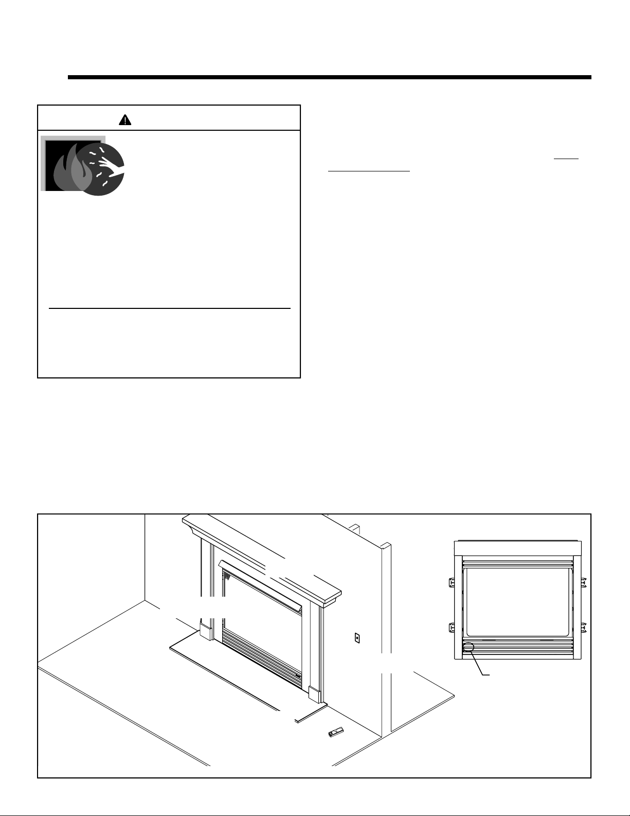
Mantel
Section 5.D.
Fixed Glass Assembly
Section14.J.
Grate
(not shown)
Section 14.H.
Clear Space
Section 2.D.
Hearth
(not required)
WARNING! DO NOT operate fi replace before reading
and understanding operating instructions. Failure
to operate fi replace according to operating instructions
could cause fi re or injury.
Wall Switch for Fan
Section 12.F.
Outside Air Kit
(behind panel)
Section 9.A.
Figure 2.1 Fireplace Components
Remote Control
Heatilator • Caliber BV Series • 4040-262 Rev J • 10/088
Page 9
C. Fan Kit (optional)
• Refer to Figure 2.1 for location of control.
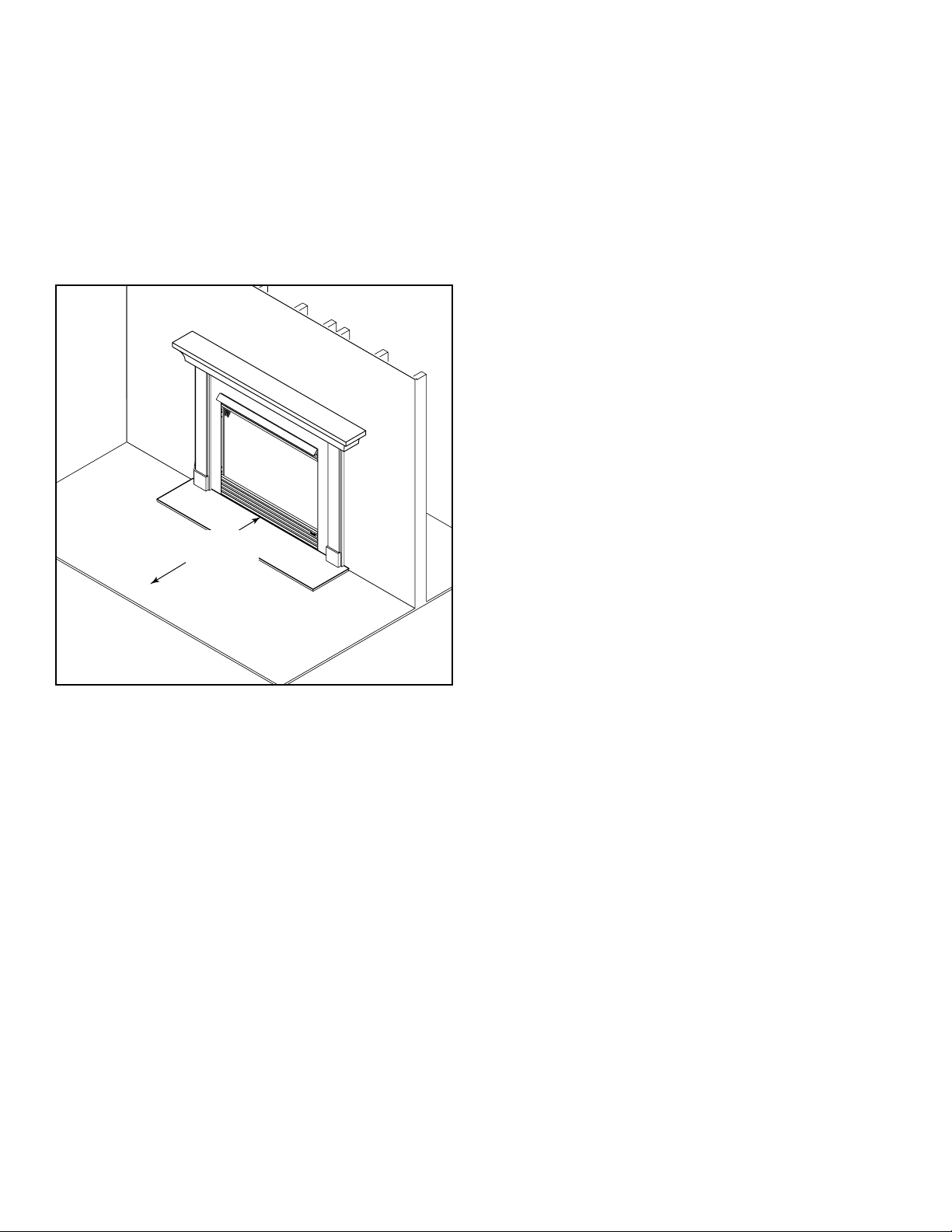
D. Clear Space
WARNING! DO NOT place combustible objects in
front of the fi replace or block louvers. High tempera-
tures may start a fi re. See Figure 2.2.
Avoid placing candles and other heat-sensitive objects on
mantel or hearth. Heat may damage these objects.
G. Remote Controls, Wall Controls and Wall
Switches
Follow the instructions supplied with the control installed
to operate your fi replace:
For safety:
• Install a switch lock or a wall/remote control with child
protection lockout feature.
• Keep remote controls out of reach of children.
See your dealer if you have questions.
H. Outside Air (optional)
The outside air kit supplies some fresh combustion air for
your fi replace. It may help reduce the effects of negative
air pressure. (See Section 9.A.)
• Refer to Figure 2.1 for location of control.
• Close the inlet to prevent cold drafts when the fi replace
is not being used.
CAUTION! Risk of Burns! The outside air control handle
is HOT when fi replace is in operation. Adjust BEFORE
lighting fi re.
Clear Space
3 ft (0.91 m)
in front of
appliance
Figure 2.2 Clear Space
E. Decorative Doors and Fronts
WARNING! Risk of Fire! Install ONLY doors or fronts
approved by Hearth & Home Technologies. Unapproved
doors or fronts may cause fi replace to overheat.
This fi replace has been supplied with an integral barrier
to prevent direct contact with the fi xed glass panel. DO
NOT operate the fi replace with the barrier removed.
Contact your dealer or Hearth & Home Technologies if the
barrier is not present or help is needed to properly install
one.
For more information refer to the instructions supplied
with your decorative door or front.
I. Before Lighting Fireplace
Before operating this fi replace for the fi rst time, have a
qualifi ed service technician:
• Verify all shipping materials have been removed from
inside and/or underneath the fi rebox.
• Review proper placement of logs, ember material and/or
other decorative materials.
• Check the wiring.
• Check the air shutter adjustment.
• Ensure that there are no gas leaks.
• Ensure that the glass is sealed and in the proper position
and that the integral barrier is in place.
WARNING! RISK OF Fire/Asphyxiation! DO NOT operate
fi replace with fi xed glass assembly removed.
F. Fixed Glass Assembly
See Section 14.J.
Heatilator • Caliber BV Series • 4040-262 Rev J • 10/08 9
Page 10
J. Lighting Instructions (IPI)
• For normal use, activate/deactivate your fi replace with the wall switch or remote control.
• The IPI system may be operated with two D-cell batteries. When using batteries, unplug the transformer. To prolong
battery life, remove them when using the transformer.
• If your fi replace must be deactivated for serviced or an extended period of time, follow the instructions below.
This appliance needs fresh air for safe operation
FOR YOUR SAFETY READ BEFORE LIGHTING
WARNING: If you do not follow these instructions exactly, a fire
or explosion may result causing property damage,
personal injury or loss of life.
A. This appliance is equipped with an ignition device which
automatically lights the pilot. Do not try to light the pilot by
hand.
B. BEFORE LIGHTING smell all around the appliance area for
gas. Be sure to smell next to the floor because some gas is
heavier than air and will settle on the floor.
WHAT TO DO IF YOU SMELL GAS
• Do not try to light any appliance.
• Do not touch any electric switch; do not use any phone in
your building.
• Immediately call your gas supplier from a neighbor's
phone. Follow the gas supplier's instructions.
• If you cannot reach your gas supplier, call the fire
department.
C. Use only your hand to push in and move the gas control
valve or turn the gas control knob. Never use tools. If the
lever or knob will not move by hand, don't try to repair it, call
a qualified service technician. Force or attempted repair may
result in a fire or explosion.
D. Do not use this appliance if any part has been under water.
Immediately call a qualified service technician to inspect the
appliance and to replace any part of the control system and
any gas control which has been under water.
LIGHTING INSTRUCTIONS
1. STOP! Read the safety information above on this label.
2. Turn wall switch to the "OFF" position or thermostat to the
lowest setting.
3. Turn off all electric power to the appliance.
4. This appliance is equipped with an ignition device which
automatically lights the pilot. Do NOT try to light the pilot by
hand.
5. Wait five minutes to clear out any gas. If you then smell gas, STOP!
Follow "B" in the safety information above on this label. If you don't
smell gas, go to the next step.
6. To turn on the burner, turn on all electric power to this appliance and
turn on the wall switch or set the thermostat to the desired setting.
7. If the appliance will not operate, follow the instructions "TO TURN OFF
GAS TO APPLIANCE" and call your service technician or gas supplier.
and must be installed so there are provisions for
adequate combustion and ventilation air.
This appliance must be installed in accordance with
local codes, if any; if not, follow ANSI Z223.1 or, in
Canada, current CAN/CGA-B149.
This appliance must be properly connected to a
venting system in accordance with the
manufacturer's installation instructions.
WARNING:
adjustment, alteration, service or maintenance can
cause injury or property damage. Refer to the
owner's information manual provided with the
appliance. For assistance or additional information
consult a qualified installer, service agency or the
gas supplier.
CAUTION:
not touch. Keep children, clothing, furniture,
gasoline and other liquids having flammable vapors
away.
Improper installation,
Hot while in operation. Do
WARNING RISK OF FIRE
This appliance is intended to burn a specified gas
fuel only. Do not attempt to use with solid wood fuel
or another type of fuel. Do not attempt to modify or
use any other type of gas burner system.
TO TURN OFF GAS TO APPLIANCE
1. Turn off wall switch or set thermostat to lowest setting.
2. Turn off all electric power to the appliance if service is to be
performed.
Due to high surface temperatures, keep children, clothing and furniture away.
Keep burner and control compartment clean. See installation and operating instructions accompanying the appliance.
3. Push the gas control lever in and move to the "OFF" position
or push the gas control lever to the "OFF" position. Do not
force.
4. Replace the control access panel.
WARNING: Disconnect the electric power
before servicing. If for any reason the original wire
supplied with the appliance must be replaced, it must
be replaced with 105° C or its equivalent.
For use with natural gas or propane. A conversion kit
as supplied by the manufacturer shall be used to
convert this appliance to the alternative fuel.
* Also certified for installation in a bedroom or a
bed-sitting room.
* For U.S. only!
NATURAL GAS
33631D
Heatilator • Caliber BV Series • 4040-262 Rev J • 10/0810
Page 11
K. After Fireplace is Lit
Initial Break-in Procedure
• The fireplace should be run three to four hours
continuously on high.
• Turn the fi replace off and allow it to completely cool.
• Remove fi xed glass assembly. See Section 14.J.
• Clean fi xed glass assembly. See Section 3.
• Replace the fi xed glass assembly and run continuously
on high an additional 12 hours.
This cures the materials used to manufacture the fi re-
place.
NOTICE! Open windows for air circulation during fi replace
break-in.
• Some people may be sensitive to smoke and
odors.
• Smoke detectors may activate.
L. Frequently Asked Questions
ISSUE SOLUTIONS
Condensation on the glass
Blue fl ames
Odor from fi replace
Film on the glass
Metallic noise
This is a result of gas combustion and temperature variations. As the fi replace warms, this
condensation will disappear.
This is a result of normal operation and the fl ames will begin to yellow as the fi replace is al-
lowed to burn for 20 to 40 minutes.
When fi rst operated, this fi replace may release an odor for the fi rst several hours. This is
caused by the curing of materials from manufacturing. Odor may also be released from
fi nishing materials and adhesives used near the fi replace. These circumstances may require
additional curing related to the installation environment.
This is a normal result of the curing process of the paint and logs. Glass should be cleaned
within 3 to 4 hours of initial burning. A non-abrasive cleaner such as gas appliance glass
cleaner may be necessary. See your dealer.
Noise is caused by metal expanding and contracting as it heats up and cools down, similar to
the sound produced by a furnace or heating duct. This noise does not affect the operation or
longevity of the fi replace.
Heatilator • Caliber BV Series • 4040-262 Rev J • 10/08 11
Page 12

3
3
Maintenance and Service
Any safety screen or guard removed for servicing must be
replaced prior to operating the fi replace.
When properly maintained, your fi replace will give you
many years of trouble-free service. We recommend annual service by a qualifi ed service technician.
A. Maintenance Tasks-Homeowner
Installation and repair should be done by a qualifi ed service
technician only. The fi replace should be inspected before use
and at least annually by a professional service person.
The following tasks may be performed annually by the
homeowner. If you are uncomfortable performing any of
the listed tasks, please call your dealer for a service appointment.
More frequent cleaning may be required due to lint from
carpeting or other factors. Control compartment, burner
and circulating air passageway of the fi replace must be
kept clean.
CAUTION! Risk of Burns! The fi replace should be
turned off and cooled before servicing.
Glass Cleaning
Frequency: Seasonally
By: Homeowner
Tools Needed: Protective gloves, glass cleaner, drop cloth
and a stable work surface.
CAUTION! Handle fi xed glass assembly with care.
Glass is breakable.
Doors, Surrounds, Fronts
Frequency: Annually
By: Homeowner
Tools needed: Protective gloves, stable work surface
• Assess condition of screen and replace as necessary.
• Inspect for scratches, dents or other damage and repair
as necessary.
• Check that louvers are not blocked.
• Vacuum and dust surfaces.
Remote Control
Frequency: Seasonally
By: Homeowner
Tools needed: Replacement batteries and remote control in-
structions.
• Locate remote control transmitter and receiver.
• Verify operation of remote. Refer to remote control
operation instructions for proper calibration and setup
procedure.
• Place batteries as needed in remote transmitters and
battery-powered receivers.
• Place remote control out of reach of children.
If not using your fi replace for an extended period of time
(summer months, vacations/trips, etc), to prevent unintended operation:
• Remove batteries from remote controls.
• Unplug 3 volt adapter plug on IPI models.
• Avoid striking, scratching or slamming glass
• Avoid abrasive cleaners
• DO NOT clean glass while it is hot
• Prepare a work area large enough to accommodate fi xed
glass assembly and door frame by placing a drop cloth
on a fl at, stable surface.
Note: Fixed glass assembly and gasketing may have residue that
can stain carpeting or fl oor surfaces.
• Remove door or decorative front from fi replace and set
aside on work surface.
• See Section 14.J. for instructions to remove fi xed glass
assembly.
• Clean glass with a non-abrasive commercially available
cleaner.
- Light deposits: Use a soft cloth with soap and
water
- Heavy deposits: Use commercial fi replace glass
cleaner (consult with your dealer)
• Carefully set fi xed glass assembly in place on fi replace.
Hold glass in place with one hand and secure glass
latches with the other hand.
• Reinstall door or decorative front.
Heatilator • Caliber BV Series • 4040-262 Rev J • 10/0812
Venting
Frequency: Seasonally
By: Homeowner
Tools needed: Protective gloves and safety glasses.
• Inspect venting and termination cap for blockage or
obstruction such plants, bird nests, leaves, snow, debris,
etc.
• Verify termination cap clearance to subsequent
construction (building additions, decks, fences, or
sheds). See Section 6.
• Inspect for corrosion or separation.
• Verify weather stripping, sealing and fl ashing remains
intact.
• Inspect draft shield to verify it is not damaged or missing.
Page 13

B. Maintenance Tasks-Qualifi ed Service
Technician
The following tasks must be performed by a qualifi ed
service technician.
Gasket Seal and Glass Assembly Inspection
Frequency: Annually
By: Qualifi ed Service Technician
Tools needed: Protective gloves, drop cloth and a stable work
surface.
• Inspect gasket seal and its condition.
• Inspect fi xed glass assembly for scratches and nicks
that can lead to breakage when exposed to heat.
• Confi rm there is no damage to glass or glass frame.
Replace as necessary.
• Verify that fi xed glass assembly is properly retained and
attachment components are intact and not damaged.
Replace as necessary.
Logs
Frequency: Annually
By: Qualifi ed Service Technician
Tools needed: Protective gloves.
• Inspect for damaged or missing logs. Replace as
necessary. Refer to Section 14.H. for log placement
instructions.
• Verify correct log placement and no fl ame impingement
causing sooting. Correct as necessary.
Firebox
Frequency: Annually
By: Qualifi ed Service Technician
Tools needed: Protective gloves, sandpaper, steel wool,
cloths, mineral spirits, primer and touch-up paint.
• Inspect for paint condition, warped surfaces, corrosion
or perforation. Sand and repaint as necessary.
• Replace fi replace if fi rebox has been perforated.
Burner Ignition and Operation
Frequency: Annually
By: Qualifi ed Service Technician
Tools needed: Protective gloves, vacuum cleaner, whisk
broom, fl ashlight, voltmeter, indexed drill bit set, and a manom-
eter.
• Verify burner is properly secured and aligned with pilot
or igniter.
• Clean off burner top, inspect for plugged ports, corrosion
or deterioration. Replace burner if necessary.
• Replace ember materials with new dime-size pieces.
DO NOT block ports or obstruct lighting paths. Refer to
Section 14.H. for proper ember placement.
• Verify batteries have been removed from battery backup IPI systems to prevent premature battery failure or
leaking.
• Check for smooth lighting and ignition carryover to all
ports. Verify that there is no ignition delay.
• Inspect for lifting or other fl ame problems.
• Verify air shutter setting is correct. See Section 14 for
required air shutter setting. Verify air shutter is clear of
dust and debris.
• Inspect orifi ce for soot, dirt and corrosion. Verify orifi ce
size is correct. See Service Parts List for proper orifi ce
sizing.
• Verify manifold and inlet pressures. Adjust regulator as
required.
• Inspect pilot fl ame pattern and strength. See Figure 3.1
for proper pilot fl ame pattern. Clean or replace orifi ce
spud as necessary.
• Inspect thermocouple/thermopile or IPI fl ame sensing
rod for soot, corrosion and deterioration. Clean with
emery cloth or replace as required.
• Verify that there is not a short in fl ame sense circuit by
checking continuity between pilot hood and fl ame sense
rod. Replace pilot as necessary.
Control Compartment and Firebox Top
Frequency: Annually
By: Qualifi ed Service Technician
Tools needed: Protective gloves, vacuum cleaner, dust cloths
• Vacuum and wipe out dust, cobwebs, debris or pet hair.
Use caution when cleaning these areas. Screw tips that
have penetrated the sheet metal are sharp and should
be avoided.
• Remove all foreign objects.
• Verify unobstructed air circulation.
Heatilator • Caliber BV Series • 4040-262 Rev J • 10/08 13
Figure 3.1 IPI Pilot Flame Patterns
Page 14

4
4
A. Typical Appliance System
NOTICE: Illustrations and photos refl ect typical installations and are for design purposes only. Illustrations/diagrams are not
drawn to scale. Actual product may vary from pictures in manual
Getting Started
Vertical Termination Cap
Noncombustible roof
flashing maintains minimum
clearance around pipe
Storm Collar
Vent pipe penetrates roof,
preferably without affecting
roof rafters
Installer Guide
Listed B-Vent Pipe
Ceiling Firestop
on floor of attic
Framing/Header
(SECTION 5)
Attic insulation shield (not shown) must be used here to
keep insulation away from vent pipe if attic is insulated.
Framing Headed off
in Ceiling Joists
(SECTION 8)
Optional
Wall Switch
Mantel & Mantel Leg
(SECTION 13)
Surround
Hearth Extension
(not required)
Gas Line
(SECTION 11)
Figure 4.1 Typical System
Heatilator • Caliber BV Series • 4040-262 Rev J • 10/0814
Page 15

B. Design and Installation Considerations
Heatilator B-type vent gas appliances are designed to
operate with all exhaust gases expelled to the outside of
the building, and combustion air pulled from the room.
Installation MUST comply with local, regional, state and
national codes and regulations. Consult insurance carrier,
local building inspector, fi re offi cials or authorities having
jurisdiction over restrictions, installation inspection and
permits.
Before installing, determine the following:
• Where the appliance is to be installed.
• The vent system confi guration to be used.
• Gas supply piping.
• Electrical wiring requirements.
• Framing and fi nishing details.
• Whether optional accessories—devices such as a fan,
wall switch, or remote control—are desired.
Improper installation, adjustment, alteration, service or
maintenance can cause injury or property damage. For
assistance or additional information, consult a qualifi ed
service technician, service agency or your dealer.
C. Tools and Supplies Needed
Before beginning the installation be sure that the following tools and building supplies are available.
Gloves Safety glasses
Tape measure Framing material
Pliers Flat blade screwdriver
Hammer Phillips screwdriver
Voltmeter Electric drill and bits (1/4 in.)
Plumb line Framing square
Level Reciprocating saw
Manometer
1/2 - 3/4 in. length, #6 or #8 Self-drilling screws
High temperature caulking material
Noncorrosive leak check solution
D. Inspect Appliance and Components
The following B-vent components are needed for installation.
• Fireplace Box
• Pipe Components
• Firestops
• Attic Insulation Shield
• Elbows
• Strapping
• Roof Flashing or Chase Top
• Termination Cap
• Storm Collar
• Carefully remove the appliance and components from
the packaging.
• The vent system components and decorative doors and
fronts may be shipped in separate packages.
• If packaged separately, the log set and appliance grate
must be installed.
• Report to your dealer any parts damaged in shipment,
particularly the condition of the glass.
• Read all of the instructions before starting the installation.
Follow these instructions carefully during the installation
to ensure maximum safety and benefi t.
WARNING! Risk of Fire or Explosion! Damaged parts
could impair safe operation. DO NOT install damaged,
incomplete or substitute components. Keep appliance dry.
Hearth & Home Technologies disclaims any responsibility for,
and the warranty will be voided by, the following actions:
• Installation and use of any damaged appliance or vent system
component.
• Modifi cation of the appliance or vent system.
• Installation other than as instructed by Hearth & Home
Technologies.
• Improper positioning of the gas logs or the glass door.
• Installation and/or use of any component part not approved
by Hearth & Home Technologies.
Any such action may cause a fi re hazard.
WARNING! Risk of Fire, Explosion or Electric Shock!
DO NOT use this appliance if any part has been under wa-
ter. Call a qualifi ed service technician to inspect the appli-
ance and to replace any part of the control system and/or
gas control which has been under water.
Heatilator • Caliber BV Series • 4040-262 Rev J • 10/08 15
Page 16

E. Negative Pressure
WARNING! Asphyxiation Risk! Negative pressure can
cause spillage of combustion fumes and soot. Fireplace
needs to draft properly for safety.
Draft is the pressure difference needed to vent fi replaces
successfully. Considerations for successful draft include:
• Preventing negative pressure
• Location of fi replace and chimney
Negative pressure results from the imbalance of air
available for the fi replace to operate properly. Causes for
this imbalance include:
• Exhaust fans (kitchen, bath, etc.)
• Range hoods
• Combustion air requirements for furnaces, water heaters
and other combustion appliances
• Clothes dryers
• Location of return-air to furnace or air conditioning
• Imbalances of the HVAC air handling system
• Upper level air leaks (recessed lighting, attic hatch
opening, duct leaks)
To minimize the effects of negative air pressure, the following must be considered:
• Install the fresh air kit. Install the intake on the side of
the house towards prevailing winds during the heating
season.
• Ensure adequate outdoor air is supplied for combustion
appliances and exhaust equipment.
• Ensure furnace and air conditioning return vents are not
located in the immediate vicinity of the fi replace.
• Avoid installing the fi replace near doors, walkways or
small isolated spaces.
• Recessed lighting should be of “sealed can” design; attic
hatches weather stripped or sealed; and attic mounted
ductwork and air handler joints and seams taped or
sealed.
• Basement installations should be avoided due to stack
effect. Stack effect creates negative pressure in lower
levels. Hearth & Home Technologies recommends the
use of direct vent fi replaces in basements.
Location of the fi replace and chimney will affect perfor-
mance. As shown in Figure 4.2, the chimney should:
• Be installed through the warm space enclosed by the
building envelope. This helps to produce more draft,
especially during lighting and die-down of the fi re.
• Penetrate the highest part of the roof. This minimizes
the effects of wind turbulence.
• Be located away from trees, adjacent structures, uneven
roof lines and other obstructions.
Offsets can restrict draft so their use should be minimized. Consider the fi replace location relative to fl oor
and ceiling and attic joists.
Figure 4.2
Windward
Location
Not
Recommended
Marginal
Location
Recommended
Location
Multi-level Roofs
Recommended
Location
Location
Not
Recommended
Leeward
Heatilator • Caliber BV Series • 4040-262 Rev J • 10/0816
Page 17

5
5
Framing and Clearances
A. Selecting Appliance Location
When selecting a location for the appliance it is important to consider the required clearances to walls, Figures 5.1 and
5.2.
WARNING! Risk of Fire or Burns! Provide adequate
clearance around air openings and for service access. Due
to high temperatures, the appliance should be located out
of traffi c and away from furniture and draperies.
1/2 in.
(13 mm)
B
B
E
A
NOTICE: Illustrations refl ect typical installations and are
FOR DESIGN PURPOSES ONLY. Illustrations/diagrams
are not drawn to scale. Actual installation may vary due to
individual design preference.
C
Drywall
A
A
D
C
48 in.
(1219 mm)
max.
Model # ABCDE
CB4236IR in. 42 50-5/8 23-1/2 44 71-5/8
mm 1, 067 1286 597 1118 1819
CB4842IR in. 48 55-1/4 2 3 -1/2 50 7 8 -1/4
mm 1,219 1403 597 1270 1988
Figure 5.1 Appliance Locations
B. Constructing the Appliance Chase
A chase is a vertical box-like structure built to enclose the
gas appliance and/or its vent system. In cooler climates
the vent should enclosed inside the chase.
NOTICE: Treatment of ceiling fi restops and wall shield
fi restops and construction of the chase may vary with the
type of building. These instructions are not substitutes for the
requirements of local building codes. Therefore, you MUST
check local building codes to determine the requirements
to these steps.
Chases should be constructed in the manner of all outside walls of the home to prevent cold air drafting problems. The chase should not break the outside building
envelope in any manner.
Walls, ceiling, base plate and cantilever fl oor of the chase
should be insulated. Vapor and air infi ltration barriers
should be installed in the chase as per regional codes for
the rest of the home. Additionally, in regions where cold
air infi ltration may be an issue, the inside surfaces may
be sheetrocked and taped for maximum air tightness. To
further prevent drafts, the wall shield and ceiling fi re-
stops should be caulked with high temperature caulk to
seal gaps. Gas line holes and other openings should
be caulked with high temp caulk or stuffed with unfaced
insulation. If the appliance is being installed on a cement
slab, a layer of plywood may be placed underneath to
prevent conducting cold up into the room.
Heatilator • Caliber BV Series • 4040-262 Rev J • 10/08 17
Page 18

C. Clearances
WARNING! Risk of Fire! Maintain specifi ed air space
clearances to appliance and vent pipe:
• Insulation and other materials must be secured to
prevent accidental contact.
• The chase must be properly blocked to prevent blown
insulation or other combustibles from entering and
making contact with fi replace or chimney.
• Failure to maintain airspace may cause overheating and
a fi re.
Note: The appliance must be raised 1 1/4 in. (32 mm) off fl oor so
the Harbor System can be used. Adjust framing and vent locations
accordingly.
1/2 in. (13 mm)
1/2 in.
(13 mm)
Drywall
NOTICE: Install appliance on hard metal or wood surfaces
extending full width and depth. DO NOT install directly on
carpeting, vinyl, tile or any combustible material other than
wood.
Note: If the inside of the framed cavity is to be fi nished,
the framing dimensions must include the fi nished surface.
Example: If drywall is to be attached to the rear wall, the
depth must be measured from the drywall surface.
Note: All pipe clearance
specifications are per vent
manufacturer's installation
instructions.
Per Vent
Manufacturer’s
Specifications
Combustible flooring may be installed
next to the front of the appliance.
30 in.
(762 mm)
clearance to ceiling
36 in.
(914 mm)
0 in.
Combustible Object
0 in.
0 (Clearance to
Standoffs)
B
C
A
A
Rough Opening
Model
CB4236I in. 42 38-3/4 23-1/2
mm 1,067 984 597
CB4842I in. 48 38-3/4 23-1/2
mm 1,219 984 597
(Width)
Rough Opening
B
(Height)
C
Rough Opening
(Depth)
Figure 5.2 Clearances to Combustibles
Heatilator • Caliber BV Series • 4040-262 Rev J • 10/0818
Page 19

D. Mantel and Wall Projections
WARNING! Risk of Fire! Comply with all minimum clearances as specifi ed. Framing or fi nishing material closer
than the minimums listed must be constructed entirely
of noncombustible materials (i.e., steel studs, concrete
board, etc).
Mantels
8
7
6
5
4
3
6-1/4
5-1/2
5
8-1/2
7-3/4
7
9
9-1/4
10
10
11
10-3/4
12
11-1/2
13
12-1/4
14
13
15
13-3/4
30 in. minimum
to ceiling
17
16
15-1/4
14-1/2
18
16
Measured from top of hood (in inches)
Figure 5.3 Minimum Vertical and Maximum Horizontal Dimensions of Combustibles
Mantel Legs or Wall Projections
Top of
Appliance
A
B
Perpendicular Wall
1 in. (25 mm) min.
A
to perpendicular wall
3-1/2 in. (89 mm) min.
B
from fireplace opening
to perpendicular wall
Mantel Leg or
Drywall
Figure 5.4 Combustible Mantel Leg or Wall Projections
(Acceptable on both sides of opening)
Heatilator • Caliber BV Series • 4040-262 Rev J • 10/08 19
Page 20

6
6
Termination Locations
A. Vent Termination Minimum Clearances
WARNING
Fire Risk.
Maintain vent clearance to combustibles as
specifi ed.
• DO NOT pack air space with insulation or other
materials.
Failure to keep insulation or other materials away
from vent pipe may cause overheating and fi re.
8 ft
(2.44 m)
Lowest
Discharge
Termination
Cap
Storm Collar
Roof
Flashing
Roof Pitch H (Min.) Ft. Roof Pitch H (Min.) Ft.
Flat to 6/12 1.0* Over 11/12 to 12/12 4.0
Over 6/12 to 7/12 1.25* Over 12/12 to 14/12 5.0
Over 7/12 to 8/12 1.5* Over 14/12 to 16/12 6.0
Over 8/12 to 9/12 2.0* Over 16/12 to 18/12 7.0
Over 9/12 to 10/12 2.5 Over 18/12 to 20/12 7.5
Over 10/12 to 11/12 3.25 Over 20/12 to 21/12 8.0
* 3 ft. minimum in snow regions
Opening
12
H (min.) - Minimum height
from roof to lowest
discharge opening.
Vertical
wall
X
Roof Pitch
is X / 12
B-Vent Gas, Wood or Fuel
Oil Termination
8 ft
A
18 in.
(457 mm)
B
(2.44 m)
(minimum) to
Perpendicular
Wall
(BV only)
Gas
Termination
Termination Caps Staggered Height
A Gas Termination Wood or Fuel Oil Termination
B 6 in.
Wood, Gas or
Fuel Oil
Termination
(152 mm) min. 20 in. (508 mm) min.
B-Vent Gas, Wood or Fuel
Oil Termination
8 ft
(2.44 m)
(minimum) to
20 in. min. *
(508 mm)
Perpendicular
Wall
(BV only)
Figure 6.1 Minimum Height From Roof To Lowest Discharge
Opening
Heatilator • Caliber BV Series • 4040-262 Rev J • 10/0820
Termination Caps Same Height
* If using decorative cap cover(s), this distance may
need to be increased. Refer to the installation instruc tions supplied with the decorative cap cover.
Figure 6.2 Termination Cap Clearances
Page 21

7
7
Vent Information and Diagrams
A. Vent Guidelines
WARNING! Fire Risk/Asphyxiation! This appliance requires the specifi ed pipe for operation. Incorrect pipe may
cause spillage, condensation and overheating.
These models require the 5 in. (127 mm) B-vent double
wall vent pipe.
• This system MUST terminate vertically.
• Follow pipe manufacturer’s installation guidelines when
installing the appliance.
WARNING! Fire Risk/Explosion/Asphyxiation! DO NOT
connect this gas appliance to a chimney fl ue serving a
separate solid-fuel or gas burning appliance.
• Vent this appliance directly outside.
• Use separate vent system for this appliance.
May impair safe operation of this appliance or other
appliances connected to the fl ue.
B. Vent System Confi guration
CAUTION! Risk of Fire! ALL vent confi guration specifi -
cations MUST be followed. This product is tested and listed
to these specifi cations. Appliance performance will suffer if
specifi cations are not followed.
clearances are
manufacturer's
specifications
12 ft (3.66 m) min.
60 ft (18.29 m) max.
Figure 7.1 Vertical Termination Clearances
Vent supports
are per vent
manufacturer’s
specifications.
plumber's strap
Vent supports are per
vent manufacturer's
specifications
Metal
Plumbers'
Strap
Minimum
per vent
Metal
secured to
framing
Rise to Run Ratio = 2:1
Maximum Total Horizontal Run = 30 Feet
Minimum Total Vertical Rise = 12 Feet
Maximum Total Vertical Rise = 60 Feet
Maximum Number of Elbows: Four 90º or Eight 45º
WARNING! Risk of Fire or Explosion! Insulation and
other combustibles must not infringe on clearances.
• ALWAYS maintain specifi ed clearances around venting
and fi restop systems.
• Install fi restops as specifi ed.
Failure to keep insulation or other material away from vent
pipe may cause fi re.
Maximum horizontal run is 50% of
vertical. Horizontal run cannot be
more than 30 ft. (9.14 m).
Figure 7.2 Maximum Horizontal Run
Maximum
horizontal
30 ft (9.14 m)
45°
Elbow
90°
Elbow
Offsets exceeding
45° adapt horizontal
Note: Maximum horizontal
distance is 50% of vertical
vent height.
limitations
Figure 7.3 Maximum Horizontal Run
Heatilator • Caliber BV Series • 4040-262 Rev J • 10/08 21
Page 22

8
8
Vent Clearances and Framing
A. Pipe Clearances to Combustibles
Vent clearances are per vent manufacturer’s specifi ca-
tions. The vent MUST be Listed B-Vent pipe.
WARNING! Risk of Fire! MAINTAIN AIR space clearance
to vent. DO NOT pack insulation or other combustibles:
• Between ceiling fi restops
• Between wall shield fi restops
• Around vent system
Failure to keep insulation or other material away from vent
pipe may cause over heating and fi re.
B. Wall and Ceiling Penetration Framing
For a wall or ceiling penetration consult B-vent pipe
manufacturer’s instructions to provide adequate clearances. Use same size framing materials as those used in
the wall or ceiling construction. Firestop spacers must
be used in wall and ceiling penetrations per the B-Vent
pipe manufacturer’s specifi cations and national, regional
and local codes.
Note: MUST terminate vertically.
C. Vertical Penetration Framing
WARNING! Fire Risk. DO NOT allow loose materials or
insulation to touch vent. Hearth & Home Technologies Inc.
requires the use of an attic shield.
The National Fuel Gas Code ANSI Z223.1 and NFPA 54
requires an attic shield constructed of 26 gauge minimum
metal that extends at least 2 in. (51 mm) above insulation.
Attic shields must meet specifi ed clearance and be se-
cured in place.
Use B-vent manufacturer’s fi restops to provide adequate
clearances.
Heatilator • Caliber BV Series • 4040-262 Rev J • 10/0822
Page 23

9
9
Appliance Preparation
A. Install Outside Air Kit Damper Assembly
CAUTION! Risk of Cuts/Abrasions/Flying Debris.
Wear protective gloves and safety glasses during installation. Sheet metal edges are sharp.
WARNING! Risk of Fire/Asphyxiation. DO NOT draw out-
side combustion air from:
• Wall, fl oor or ceiling cavity.
• Enclosed space such as an attic or garage.
• Close proximity to exhaust vents or chimneys.
Fumes or odor may result.
• The outside air kit can only be installed on the left side
of the appliance.
• Refer to the installation instructions provided with the
kit.
Flexible Duct
(not supplied)
Outside Air
Outside Air
Hood
2 Wire Ties
Plate
Assembly
C. Secure and Level the Appliance
WARNING! Risk of Fire! Prevent contact with:
• Sagging or loose insulation
• Insulation backing or plastic
• Framing and other combustible materials
Block openings into the chase to prevent entry of blown-in
insulation. Make sure insulation and other materials are
secured.
DO NOT notch the framing around the appliance
standoffs.
Failure to maintain air space clearance may cause
overheating and fi re.
The diagram shows how to properly position, level, and
secure the appliance (see Figure 9.2). Nailing tabs are
provided to secure the appliance to the framing members.
• Bend out nailing tabs on each side.
• Place the appliance into position.
• Keep nailing tabs fl ush with the framing.
• Level the appliance from side to side and front to
back.
• Shim the appliance as necessary. It is acceptable to use
wood shims underneath the appliance.
• Secure the appliance to the framing by using nails or
screws through the nailing tabs.
• Secure the appliance to the fl oor by inserting two screws
through the bottom front of the appliance.
• Hearth & Home Technologies Inc recommends using
UL181 Class 0 or Class I rigid or flexible ducting.
• Secure flex duct with metal tape, screws or wire ties.
Figure 9.1 Outside Air Kit Installation
B. Gas and Electrical Connections
If applicable, ensure that gas and electrical connections
are installed at this time.
mation) and 12 (Electrical Information).
Refer to Sections 11 (Gas Infor-
Heatilator • Caliber BV Series • 4040-262 Rev J • 10/08 23
Nailing Tabs
(both sides)
Figure 9.2 Proper Positioning and Securing of Appliance
Page 24

10
10
Installing Vent Pipe
A. Assembly of Vent Sections
This B-Vent appliance requires 5 in. B-vent double-wall
pipe. Follow the pipe manufacturer’s installation guidelines when installing the unit. This will ensure proper
operation and prevent safety hazards.
WARNING! Risk of Fire/Exhaust Fumes! Assemble
pipe sections per B-vent manufacturer’s instructions. Use
support tabs for screws. Pipe may separate if not properly joined.
B. Attach Vent to Firebox
Three tabs extend from appliance collar shield. Attach
tabs to fi rst section of B-vent pipe using self-tapping 1/4 in.
screws supplied with appliance. See Figure 10.1.
Tabs
C. Secure Vent Sections
Secure vent sections with vent supports following B-vent
manufacturer’s instructions.
WARNING! Risk of Fire or Explosion! Use vent run
supports per vent manufacturer’s installation instructions.
• Connect vent sections per vent manufacturer’s
installation instructions.
• Maintain all clearances to combustibles. Maintain
specifi ed slope (if required).
• Improper support may allow vent to sag or separate.
D. Install Attic Insulation Shield
WARNING! Fire Risk. DO NOT allow loose materials or
insulation to touch vent. Hearth & Home Technologies Inc.
requires the use of an attic shield.
The National Fuel Gas Code ANSI Z223.1 and NFPA 54
requires an attic shield constructed of 26 gauge minimum
metal that extends at least 2 in. (51 mm) above insulation.
Attic shields must meet vent manufacturer’s specifi ed
clearance and be secured in place per vent manufacturer’s instructions.
Figure 10.1 Attach Vent to Firebox
Heatilator • Caliber BV Series • 4040-262 Rev J • 10/0824
Page 25

11
11
Gas Information
A. Fuel Conversion
• Make sure the appliance is compatible with available
gas types.
• Conversions must be made by a qualified service
technician using Hearth & Home Technologies specifi ed
and approved parts.
B. Gas Pressure
• Optimum appliance performance requires proper input
pressures.
• Gas line sizing requirements will be determined in ANSI
Z221.3 National Fuel Gas Code in the USA and CAN/
CGA B149 in Canada.
• Pressure requirements are:
Gas Pressure Natural Gas Propane
Minimum inlet pressure 5.0 in. w.c. 11.0 in. w.c.
Maximum inlet pressure 7.0 in. w.c. 14.0 in. w.c.
Manifold pressure 3.5 in. w.c. 10.0 in. w.c.
WARNING! Risk of Fire or Explosion! High pressure
will damage valve. Low pressure may cause explosion.
• Verify inlet pressures. Verify minimum pressures when
other household gas appliances are operating.
• Install regulator upstream of valve if line pressure is
greater than 1/2 psig.
C. Gas Connection
• Refer to Reference Section 16.A. for location of gas line
access in appliance.
• Gas line may be run through knockout(s) provided on
either side or the bottom of the appliance.
• The gap between supply piping and gas access hole
may be caulked with high temperature caulk or stuffed
with non-combustible, unfaced insulation to prevent cold
air infi ltration.
• Ensure that gas line does not come in contact with outer
wrap of the appliance. Follow local codes.
• Pipe incoming gas line into valve compartment.
• Connect incoming gas line to the 1/2 in. (13 mm)
connection on manual shutoff valve.
WARNING! Risk of Fire or Explosion! Support control
when attaching pipe to prevent bending gas line.
• A small amount of air will be in the gas supply lines.
WARNING! Risk of Fire or Explosion! Gas build-up during line purge could ignite.
• Purge should be performed by qualified service
technician.
• Ensure adequate ventilation.
• Ensure there are no ignition sources such as sparks or
open fl ames.
Light the appliance. It will take a short time for air to purge
from lines. When purging is complete the appliance will
light and operate normally.
WARNING
Fire Risk.
Explosion Hazard.
High pressure will damage valve.
• Disconnect gas supply piping BEFORE
pressure testing gas line at test pressures
above 1/2 psig.
• Close the manual shutoff valve BEFORE
pressure testing gas line at test pressures
equal to or less than 1/2 psig.
Note: Have the gas supply line installed in accordance with local
codes, if an y. If n ot, fo llow A NSI 223.1. Ins tallat ion sho uld be done
by a qualifi ed installer approved and/or licensed as required by
the locality. (In the Commonwealth of Massachusetts installation
must be performed by a licensed plumber or gas fi tter).
Note: A listed (and Commonwealth of Massachusetts approved)
1/2 in. (13 mm) T-handle manual shut-off valve and fl exible gas
connector are connected to the 1/2 in. (13 mm) control valve
inlet.
• If substituting for these components, please consult
local codes for compliance.
WARNING! Risk of Fire, Explosion or Asphyxiation!
Check all fi ttings and connections with a non-corrosive
commercially available leak-check solution. DO NOT use
open fl ame. Fittings and connections could have loos-
ened during shipping and handling.
WARNING! Risk of Fire! DO NOT change valve settings.
This valve has been preset at the factory.
D. High Altitude Installations
NOTICE: If the heating value of the gas has been reduced,
these rules do not apply. Check with your local gas utility or
authorities having jurisdiction.
When installing above 2000 feet elevation:
• In the USA: Reduce burner orifi ce 4% for each 1000 feet
above 2000 feet.
• In CANADA: Reduce burner orifi ce 10% for elevations
between 2000 feet and 4500 feet. Above 4500 feet,
consult local gas utility.
Heatilator • Caliber BV Series • 4040-262 Rev J • 10/08 25
Page 26

12
12
Electrical Information
A. Wiring Requirements
NOTICE: This appliance must be electrically wired
and grounded in accordance with local codes or, in the
absence of local codes, with National Electric Code
ANSI/NFPA 70-latest edition or the Canadian Electric
Code CSA C22.1.
• Wire the appliance junction box to 110-120 VAC. This is
required for use of optional accessories (standing pilot
ignition) or proper operation of the appliance (Intellifi re
ignition).
• A 110-120 VAC circuit for this product must be protected
with ground-fault circuit-interrupter protection, in
compliance with the applicable electrical codes, when
it is installed in locations such as in bathrooms or near
sinks.
• Low voltage and 110 VAC voltage cannot be shared
within the same wall box.
WARNING! Risk of Shock or Explosion! DO NOT wire
110V to the valve or to the appliance wall switch. Incorrect
wiring will damage controls.
B. Intellifi re Ignition System Wiring
• Wire the appliance junction box to 110 VAC for proper
operation of the appliance.
WARNING! Risk of Shock or Explosion! DO NOT
wire IPI controlled appliance junction box to a switched
circuit. Incorrect wiring will override IPI safety lockout.
• Refer to Figure 12.1. Intellifi re Pilot Ignition (IPI) Wiring
Diagram.
• This appliance is equipped with an Intellifi re control valve
which operates on a 3 volt system.
• Plug the 3-volt AC transformer into the appliance junction
box to supply power to the unit OR install two D cell
batteries (not included) into the battery pack before
use.
NOTICE: Batteries should not be placed in the battery
pack while using the transformer. Remove batteries before
using the transformer, and unplug the transformer before
installing the batteries. Battery polarity must be correct or
module damage will occur.
C. Optional Accessories Requirements
• This appliance may be used with a wall switch, wall
mounted thermostat and/or a remote control.
• Wiring for optional Hearth & Home Technologies
approved accessories should be done now to avoid
reconstruction. Follow instructions that come with those
accessories.
D. Electrical Service and Repair
WARNING! Risk of Shock! Label all wires prior to
disconnection when servicing controls. Wiring errors can
cause improper and dangerous operation. Verify proper
operation after servicing.
WARNING! Risk of Shock! Replace damaged wire with
type 105° C rated wire. Wire must have high temperature
insulation.
Optional SPST
Wall Switch
OR
Optional Remote
Limit
Switch
GRN*
BLU
WHT
*
GRN wire only used with
optional wall switch
WSK-MLT-HTL
Figure 12.1 Intellifi re Pilot Ignition (IPI) Wiring Diagram
Heatilator • Caliber BV Series • 4040-262 Rev J • 10/0826
BLK
RED
Battery
Pack
+
-
-
+
Adaptor
3V
BLK
RED
To
Junction
Box
BRN
Valve
Control
Box
BLK
ORG
GRN
Ignitor
ORG
Flame
Sensor
Pilot Assembly
WHT
Page 27

E. Junction Box Installation
If the box is being wired from the OUTSIDE of the appliance:
• Remove the cover plate located on the outer shell - right
side (see Figure 12.2).
• Install the supplied Romex™ connector in the cover
plate.
• Make all necessary wire connections and reattach the
cover plate to the outer shell.
Romex
Connector
14/2WG
Cover Plate
outside firebox
If the box is being wired from the INSIDE of the appliance:
• Remove the screw attaching the junction box/receptacle
to the outer shell, rotate the junction box inward to
disengage it from the outer shell.
• Pull the electrical wires from outside the appliance through
this opening into the valve compartment.
• Make all necessary wire connections to the junction box/
receptacle and reassemble the junction box/receptacle
to the outer shell.
F. Wall Switch Installation for Fan (Optional)
If the box is being wired to a wall mounted switch for use
with a fan, see Figure 12.3:
• The power supply for the appliance must be brought into
a switch box.
• The power can then be supplied from the switch box
to the appliance using a minimum of 14-3 with ground
wire.
• At the switch box connect the black (hot) wire and red
(switch leg) wire to the wall switch as shown.
• At the appliance connect the black (hot), white (neutral)
and green (ground) wires to the junction box as
shown.
• Add a 1/4 in. insulated female connector to the red
(switch leg) wire, route it through the knockout in the face
of the junction box, and connect to the top fan switch
connector (1/4 in. male) as shown.
WHT
BLK
WHT
BLK
GRN wire
inside box
Copper
ground attached
to GRN screw with
GRN wire
NOTICE: DO NOT wire
110 VAC to wall switch.
Figure 12.2 Junction Box Detail
Minimum 14-3 AWG
with Ground
Junction Box
Red
Figure 12.3 Junction Box Wired to Wall Switch or BC10
Red
Black
White
Red
Black
Green
White
Green
Knockout
Switch Box
Black
White
Green
Switch
Power
Supply
Wires
Heatilator • Caliber BV Series • 4040-262 Rev J • 10/08 27
Page 28

13
13
Finishing
A. Mantel and Wall Projections
WARNING! Risk of Fire! Comply with all minimum clearances as specifi ed. Framing closer than the minimums
listed must be constructed entirely of noncombustible
materials (i.e., steel studs, concrete board, etc.) Failure to
comply could cause fi re.
Mantels
30 in. minimum
to ceiling
18
17
16
14-1/2
15-1/4
16
15
14
13
12-1/4
13-3/4
13
12
11
10
9
8
7
6
5
4
5-1/2
6-1/4
7
3
5
Figure 13.1 Minimum Vertical and Maximum Horizontal Dimensions
9-1/4
8-1/2
7-3/4
Measured from top of hood (in inches)
11- 1/2
10-3/4
10
B. Facing Material
• Metal front faces may be covered with non-combustible
materials only.
• Facing and/or fi nishing materials must not interfere with
air fl ow through louvers, operation of louvers or doors,
or access for service.
• Facing and/or fi nishing materials must never overhang
into the glass opening.
• Observe all clearances when applying combustible
materials.
• Seal joints between the fi nished wall and appliance top
and sides using a 300 °F minimum sealant. Refer to
Figure 13.3.
WARNING! Risk of Fire! DO NOT apply combustible materials beyond the minimum clearances. Comply with all
minimum clearances to combustibles as specifi ed in this
manual. Overlapping materials could ignite and will interfere with proper operation of doors and louvers.
These surfaces
may be covered
with non-combustible
material.
Non-combustible
sealant.
Mantel Legs or Wall Projections
Top of
Appliance
A
B
Mantel Leg or
Perpendicular Wall
1 in. (25 mm) min.
A
to perpendicular wall
3-1/2 in. (89 mm) min.
B
from fireplace opening
to perpendicular wall
Figure 13.2 Mantel Leg or Wall Projections (Acceptable on both
sides of opening)
Drywall
Heatilator • Caliber BV Series • 4040-262 Rev J • 10/0828
Figure 13.3 Noncombustible Facing Diagram
Page 29

14
14
Appliance Setup
A. Remove Glass Assembly
See Section J.
B. Remove the Shipping Materials
Remove shipping materials from inside or underneath the
fi rebox.
C. Clean the Appliance
Clean/vacuum any sawdust that may have accumulated
inside the fi rebox or underneath in the control cavity.
D. Accessories
Install approved accessories per instructions included
with accessories. Contact your dealer for a list of ap-
proved accessories.
WARNING! Risk of Fire and Electric Shock! Use ONLY
Hearth & Home Technologies-approved optional accessories with this appliance. Using non-listed accessories
could result in a safety hazard and will void the warranty.
E. Install the Refractory
An optional weathered brick refractory is available for this
appliance. Follow the installation instructions supplied
with the refractory.
G. Place the Rockwool
WARNING! Risk of Explosion! Follow rockwool placement
instructions. DO NOT place rockwool directly over burner
ports. Replace rockwool material annually. Improperly
placed rockwool interferes with proper burner operation.
• Rockwool is shipped with this gas appliance.
• Place a small amount of 1/2 in. diameter pieces
(dime-size) of rockwool on the burner pan so that rock
wool touches but does not cover the holes in the burner
pan.
• It is not necessary to use the entire bag. Save the
remaining amount for future use.
F. Place the Lava Rock & Vermiculite
• See Figures 14.1. 14.2. and 14.4.
• It is not necessary to use the entire bag of either product.
Save the remaining amount for future use.
Figure 14.1 Placement of Lava Rock
Figure 14.3 Placement of Rock Wool
Vermiculite and
lava rock
placement on
sides and front
of hearth pan.
Figure 14.4 Placement of Lava Rock, Vermiculite & Rock Wool
Rock wool
placement
(shaded areas)
Vermiculite and
lava rock
placement on
sides and front
of hearth pan.
Figure 14.2 Placement of Vermiculite
Heatilator • Caliber BV Series • 4040-262 Rev J • 10/08 29
Page 30

H. Install the Log Assembly
• Base logs have been permanently mounted on the grate
assembly and should not be moved. See Figure 14.5.
I. Firescreen
The fi rescreen is a protective barrier and must be at-
tached.
Removing Firescreen
• Open lower access panel and pull base of screen
towards you.
• The top of the screen will slide out of the screen retainers
at the top of the fi rebox opening.
Replacing Firescreen
• Remove top grille assembly by lifting upwards and pulling
towards you.
• Slide top of screen panel into top screen brackets and
rotate bottom of screen to lower door latches.
• Close lower access panel and reinstall top grille.
Figure 14.5 Base Logs
• Install “Y” log on left hand side of grate using locating
pins to position. See Figure 14.6.
Figure 14.6 Placing Left Top Log
• Install right top log as shown in Figure 14.7 using locating
pins to position log properly.
J. Glass Assembly
WARNING! Risk of Asphyxiation! Handle fi xed glass
assembly with care. Inspect the gasket to ensure it is
undamaged and inspect the glass for cracks, chips or
scratches.
• DO NOT strike, slam or scratch glass.
• DO NOT operate fi replace with glass removed, cracked,
broken or scratched.
• Replace as a complete assembly.
Removing Glass Assembly
• Remove fi rescreen.
• Pull the four (CB4236I) or six (CB4842I) glass assembly
latches out of the groove on the glass frame.
• Remove the glass panel from the appliance.
Replacing Glass Assembly
• Set the glass panel on the lower two or three glass
assembly latches, ensuring the glass panel is centered
in the opening.
• Pull out and latch the four/six glass assembly latches
into the groove on the glass frame.
• Replace fi rescreen.
Figure 14.7 Placing Right Top Log
Latches
(both bottom
and top)
Glass
Assembly
Figure 14.8 Fixed Glass Assembly
Heatilator • Caliber BV Series • 4040-262 Rev J • 10/0830
Page 31

K. Install Louvers and Trim
• Install optional trim kits and/or surrounds using the
instructions included with the accessory.
• Use non-combustible materials to cover the gap between
the sheet rock and the appliance (if desired).
• Do not obstruct or modify the air inlet/outlet grilles.
• Leave space to lower the bottom grille and remove the
trim door.
L. Hood
• Align back edge of hood with attachment clips and press
fi rmly in place.
M. Air Shutter Setting
Air shutter settings should be adjusted by a qualifi ed
installer at the time of installation. The air shutter is set at
the factory for minimum vertical vent run. Adjust air shutter for longer vertical runs.
• It takes 16 full turns of the shutter adjustment handle to
move the air shutter from fully open to fully closed.
• When the air shutter adjustment handle is all the way
down, the air shutter is in the closed position.
NOTICE: If sooting occurs, provide more air by opening
the air shutter.
Closed
Figure 14.9 Air Shutter
Heatilator • Caliber BV Series • 4040-262 Rev J • 10/08 31
Page 32

15
15
Troubleshooting
With proper installation, operation, and maintenance your gas appliance will provide years of trouble-free service. If you
do experience a problem, this troubleshooting guide will assist a qualifi ed service technician in the diagnosis of a problem
and the corrective action to be taken. This troubleshooting guide can only be used by a qualifi ed service technician. Con-
tact your dealer to arrange a service call by a qualifi ed service technician.
A. Intellifi re Ignition System
Symptom Possible Cause Corrective Action
1. Pilot won’t light. The ignitor/module makes noise,
but no spark.
A. Incorrect wiring. Verify “S” wire (white) for sensor and “I” wire (orange) for ignitor are
connected to correct terminals on module and pilot assembly.
B. Loose connections or electrical
shorts in the wiring.
C. Ignitor gap is too large. Verify gap of igniter to right side of pilot hood. The gap should be ap-
D. Module. Turn ON/OFF rocker switch or wall switch to OFF position. Remove
Verify no loose connections or electrical shorts in wiring from module
to pilot assembly. Verify connections underneath pilot assembly are
tight; also verify connections are not grounding out to metal chassis, pilot burner, pilot enclosure, mesh screen if present, or any other
metal object.
proximately .17 inch or 1/8 in. (3 mm).
ignitor wire “I” from module. Place a grounded wire about 3/16 in. (5
mm) away from “I” terminal on module. Place ON/OFF rocker switch
or wall switch in ON position. If there is no spark at “I” terminal module must be replaced. If there is a spark at “I” terminal, module is fi ne.
Inspect pilot assembly for shorted sparker wire or cracked insulator
around electrode. Replace pilot if necessary.
2. Pilot won’t light, there is no
noise or spark.
3. Pilot sparks, but Pilot will
not light.
A. No power or transformer in-
stalled incorrectly.
B. A shorted or loose connection
in wiring confi guration or wiring
harness.
C. Improper wall switch wiring. Verify that 110/VAC power is “ON” to junction box.
D. Module not grounded. Verify black ground wire from module wire harness is grounded to
E. Module. Turn ON/OFF rocker switch or wall switch to OFF position. Remove
A. Gas supply. Verify that incoming gas line ball valve is “open”. Verify that inlet
B. Ignitor gap is incorrect. Verify that spark gap from ignitor to pilot hood is .17 in. or 1/8 in (3
C. Module is not grounded. Verify module is securely grounded to metal chassis of appliance.
Verify that transformer is installed and plugged into module. Check
voltage of transformer under load at spade connection on module
with ON/OFF switch in ON position. Acceptable readings of a good
transformer are between 3.2 and 2.8 volts AC.
Remove and reinstall the wiring harness that plugs into module. Verify there is a tight fi t. Verify pilot assembly wiring to module. Remove
and verify continuity of each wire in wiring harness. Replace any
damaged components.
metal chassis of appliance.
ignitor wire “I” from module. Place ON/OFF rocker switch or wall
switch in ON position. If there is no spark at “I” terminal module must
be replaced. If there is a spark at “I” terminal, module is fi ne. Inspect
pilot assembly for shorted sparker wire or cracked insulator around
electrode.
pressure reading is within acceptable limits, inlet pressure must not
exceed 14 in. W.C.
mm).
D. Module voltage output / Valve/
Pilot solenoid ohms readings.
Heatilator • Caliber BV Series • 4040-262 Rev J • 10/0832
Verify battery voltage is at least 2.7 volts. Replace batteries if voltage
is below 2.7.
Page 33

A. Intellifi re Ignition System (continued)
4. Pilot lights but continues
to spark, and main burner
will not ignite. (If the pilot
continues to spark after
the pilot fl ame has been lit,
fl ame rectifi cation has not
occurred.)
A. A shorted or loose connection
in fl ame sensing rod.
B. Poor fl ame rectifi cation or con-
taminated fl ame sensing rod.
C. Module is not grounded. Verify module is securely grounded to metal chassis of appliance.
D. Damaged pilot assembly or
contaminated fl ame sensing
rod.
E. Module. Turn ON/OFF rocker switch or wall switch to OFF position. Remove
Verify all connections to wiring diagram in manual. Verify connections underneath pilot assembly are tight. Verify connections are not
grounding out to metal chassis, pilot burner, pilot enclosure or screen
if present, or any other metal object.
With fi xed glass assembly in place, verify that fl ame is engulfi ng
fl ame sensing rod on left side of pilot hood. Flame sensing rod
should glow shortly after ignition. Verify correct pilot orifi ce is in-
stalled and gas inlet is set to pressure specifi cations. Clean fl ame
sensing rod with emery cloth to remove any contaminants that may
have accumulated on fl ame sensing rod.
Verify that wire harness is fi rmly connected to the module.
Verify that ceramic insulator around the fl ame sensing rod is not
cracked, damaged, or loose. Verify connection from fl ame sensing
rod to white sensor wire. Clean fl ame sensing rod with emery cloth to
remove any contaminants that may have accumulated on fl ame sens-
ing rod. Verify continuity with a multimeter with ohms set at lowest
range. Replace pilot if any damage is detected.
ignitor wire “I” from module. Place ON/OFF rocker switch or wall
switch in ON position. If there is no spark at “I” terminal module must
be replaced. If there is a spark at “I” terminal, module is fi ne.
5. The pilot and main burner
extinguish while in operation.
A. No LP in tank. Check the LP (propane) tank. Refi ll the fuel tank.
B. Improper gas inlet pressure. Verify with manometer. NG should read 5-14 inches w.c. LP should
read 10-14 inches w.c.
C. Inner vent pipe leaking exhaust
gases back into the system.
D. Glass installed improperly. Check to ensure glass is installed properly. Replace glass panel as-
E. Improper vent cap installation. Check for proper installation and freedom from debris or blockage.
F. High limit switch has been au-
tomatically activated.
Check venting system for damage. Replace/repair improperly assembled pipe sections.
sembly.
This appliance is equipped with an auto reset high limit switch which
will shut down the appliance if it spills under fl ue blockage or exces-
sive negative pressure conditions. Shut off the appliance and the gas
supply. Do not attempt to operate the appliance until it has been examined by a qualifi ed service technician.
Heatilator • Caliber BV Series • 4040-262 Rev J • 10/08 33
Page 34

16
16
Reference Materials
A. Appliance Dimension Diagram
Dimensions are actual appliance dimensions. Use for reference only. For framing dimensions and clearances refer to Section 5.
C
23 in.
(584 mm)
15-1/4 in.
(387 mm)
A
Gas Line
Access
3 in.
(76 mm)
6-1/2 in.
(165 mm)
Figure 16.1 Appliance Dimensions
38-1/4 in.
(972 mm)
33-1/2 in.
(851 mm)
B
Model A B C
CB4236IR inches 41-1/4 36 24-1/4
mm 1,048 914 616
CB4842IR inches 47-1/4 42 30-1/4
mm 1,200 1067 768
1-1/2 in.
(38 mm)
2-3/8 in.
(60 mm)
Electrical
Access
14-1/8 in.
(359 mm)
Gas Line
Access
5-7/8 in.
(149 mm)
38-1/2 in.
(978 mm)
2 in.
(51 mm)
Heatilator • Caliber BV Series • 4040-262 Rev J • 10/0834
Page 35

B. Service Parts List
Stocked
at Depot
CB4236IR
Ending Manufacturing Date: Active
Beginning Manufacturing Date: Jan 2005
Service Parts List
Service Parts
Caliber Gas Fireplace
Pre GA1647700 4040-206
Post GA1647700 4000-316
Pre GA1563745 4040-059
Post GA1563745 4040-063
08/08
Log/Grate Assembly 4040-051 X
1 Front Y Log 4040-200
ITEM DESCRIPTION COMMENTS PART NUMBER
IMPORTANT: THIS IS DATED INFORMATION. When requesting service or replacement
parts for your appliance please provide model number and serial number. All parts listed
in this manual may be ordered from an authorized dealer.
CB4236IR
Ending Manufacturing Date: Active
Beginning Manufacturing Date: Jan 2005
7
Service Parts
Caliber Gas Fireplace
Service Parts Diagram
Top Log Assembly 4040-038
2 Front Log 4040-201
3 Top Y Log 4040-202
4 Top Log 4040-203
8
5 Middle Log
6 Back Log Assembly 4040-207
9
Lava Rock (3lb. Bag) 4021-297
Mineral Wool 14333B
Vermiculite (small) 28746
Battery Pack 593-594A X
Gas Access Panel 31636
Glass Kit w/Screen 4040-033
Installation Instructions Caliber II 4040-225
Lava Rock Bag Assembly 4040-094
7 Glass Clip Support Assembly Qty. 4 req. 33858 X
8 Burner Pan Assembly 4040-093 X
9 Handle Bracket 34636
11 Hearth Pan 4040-255
10 Grate Retainer 4040-272
12 Burner Support 4040-259
13 Glass Heat Shield 4040-153
14 Glass/Frame Assembly 4040-087 X
15 Hood 29575
16 Grille Assembly - Upper 4031-082
17 Screen Assembly 4040-031 X
18 Grille Assembly - Lower 25016
19 Valve Assembly
20 Junction Box Cover Plate 4031-222
21 Junction Box (Plastic) 4021-013 X
22 Junction Box Radiation Shield 4031-193
22
21
20
19
Limit Switch 4021-642 X
Nailing Flange Qty. 4 req. 31190
Refractory Back 4040-298
Screen Bracket Qty. 2 req. 28159
Additional service part numbers appear on following page.
08/08
2
4
5
6
3
1
12
11
10
13
14
Log Set Assembly
17
15
16
18
Part number list on following page.
Heatilator • Caliber BV Series • 4040-262 Rev J • 10/08 35
Page 36

B. Service Parts List (continued)
Stocked
at Depot
CB4842IR
Ending Manufacturing Date: Active
Beginning Manufacturing Date: Jan 2005
Pre GA1647700 4040-206
Post GA1647700 4000-316
Service Parts List
Service Parts
Caliber Gas Fireplace
Pre GA1563745 4040-059
Post GA1563745 4040-063
08/08
Log/Grate Assembly 4040-052 X
1 Front Y Log 4040-200
ITEM DESCRIPTION COMMENTS PART NUMBER
IMPORTANT: THIS IS DATED INFORMATION. When requesting service or replacement
parts for your appliance please provide model number and serial number. All parts listed
in this manual may be ordered from an authorized dealer.
CB4842IR
Ending Manufacturing Date: Active
Beginning Manufacturing Date: Jan 2005
7
Service Parts
Caliber Gas Fireplace
Service Parts Diagram
Top Log Assembly 4040-038
2 Front Log 4040-201
3 Top Y Log 4040-202
4 Top Log 4040-203
8
5 Middle Log
6 Back Log Assembly 4040-208
9
Lava Rock (3lb. Bag) 4021-297
Mineral Wool 14333B
Vermiculite (small) 28746
Battery Pack 593-594A X
Installation Instructions Caliber II 4040-225
Gas Access Panel 31636
Glass Kit w/Screen 4040-034
Lava Rock Bag Assembly 4040-094
7 Glass Clip Support Assembly Qty. 6 req. 33858 X
8 Burner Pan Assembly 4040-093 X
9 Handle Bracket 34636
11 Hearth Pan 4040-256
10 Grate Retainer 4040-272
12 Burner Support 4040-259
13 Glass Heat Shield 4040-154
14 Glass/Frame Assembly 4040-088 X
15 Hood 29576
16 Grille Assembly - Upper 4031-083
17 Screen Assembly 4040-032 X
18 Grille Assembly - Lower 25144
19 Valve Assembly
20 Junction Box Cover Plate 4031-222
21 Junction Box (Plastic) 4021-013 X
22 Junction Box Radiation Shield 4031-193
22
21
20
19
Limit Switch 4021-642 X
Nailing Flange Qty. 4 req. 31190
Refractory Back 4040-299
Screen Bracket Qty. 2 req. 28159
Additional service part numbers appear on following page.
08/08
2
4
5
6
3
1
Log Set Assembly
12
11
10
13
14
17
15
16
18
Part number list on following page.
Heatilator • Caliber BV Series • 4040-262 Rev J • 10/0836
Page 37

B. Service Parts List (continued)
CB4842IR
Ending Manufacturing Date: Active
Beginning Manufacturing Date: Jan 2005
2
1
3
Valve Assembly Parts List
Service Parts
Caliber Gas Fireplace
4
13
11
10
12
6
5
7
08/08
Stocked
at Depot
14
4047-126
15
Pre GA1563745 4040-059
Post GA1563745 4040-063
Pre GA1563745 4040-273
Post GA1563745
Thru June 2008
Post June 2008 4047-144
Pre GA1563745 4021-005 X
9
8
Post GA1563745 4021-324 X
IPI Valve Assembly
CB4236IR
Ending Manufacturing Date: Active
Beginning Manufacturing Date: Jan 2005
2
1
3
Valve Assembly Parts List
Service Parts
Caliber Gas Fireplace
4
Valve Assembly
1 Shutter Box Top 4040-190
2 Shutter Box Bottom 4040-189
3 Pilot Bracket
ITEM DESCRIPTION COMMENTS PART NUMBER
IMPORTANT: THIS IS DATED INFORMATION. When requesting service or replacement
parts for your appliance please provide model number and serial number. All parts listed
in this manual may be ordered from an authorized dealer.
4 Pilot Assembly
5 Valve Bracket - Upper 4040-193
6 Valve Bracket - Lower 31824
Threaded Orifi ce (.104) NG 4031-158 X
7 Flex Ball Valve Assembly 302-320A X
8 Valve - NG 750-500 X
9 3/8 Flare x 3/8 NPT Elbow 4021-045
11
10 Bulkhead 4031-192 X
12 Bulkhead Insulation 4021-043
Wall Switch Wire Assembly M/M 4018-018 X
13 Wire Assembly 593-590A X
14 3V Adapter Plug 593-593A X
15 Control Module 593-592 X
08/08
Stocked
at Depot
14
13
15
11
10
12
5
9
8
6
7
Pre GA1563745 4040-059
Post GA1563745 4040-063
4047-126
Pre GA1563745 4040-273
Post GA1563745
Thru June 2008
Post June 2008 4047-144
Pre GA1563745 4021-005 X
Post GA1563745 4021-324 X
IPI Valve Assembly
Valve Assembly
1 Shutter Box Top 4040-190
2 Shutter Box Bottom 4040-189
3 Pilot Bracket
ITEM DESCRIPTION COMMENTS PART NUMBER
IMPORTANT: THIS IS DATED INFORMATION. When requesting service or replacement
parts for your appliance please provide model number and serial number. All parts listed
in this manual may be ordered from an authorized dealer.
4 Pilot Assembly
5 Valve Bracket - Upper 4040-193
6 Valve Bracket - Lower 31824
7 Flex Ball Valve Assembly 302-320A X
8 Valve - NG 750-500 X
9 3/8 Flare x 3/8 NPT Elbow 4021-045
10 Bulkhead 4031-192 X
Threaded Orifi ce (.101) NG 4021-200 X
11
12 Bulkhead Insulation 4021-043
Wall Switch Wire Assembly M/M 4018-018 X
13 Wire Assembly 593-590A X
14 3V Adapter Plug 593-593A X
15 Control Module 593-592 X
Heatilator • Caliber BV Series • 4040-262 Rev J • 10/08 37
Page 38

C. Optional Components
Arts & Crafts Faux Front
FFCAC
Refractory Kit
WTBC36DB - For 36 in. BV
WTBC42DB - For 42 in. BV
Modernist Faux Front
FFCM
Jamestown Faux Front
FFCJ
Contact your dealer for a complete listing of optional components.
Heatilator • Caliber BV Series • 4040-262 Rev J • 10/0838
Page 39

C. Optional Components (continued)
Model # Description
FFCM36-B Modernist-style black decorative faux front
FFCM36PT Modernist-style pewter decorative faux front
FFCM36BN Modernist-style brushed nickel decorative faux front
FFCAC36-B Arts & Crafts-style black decorative faux front
FFCAC36PT Arts & Crafts-style pewter decorative faux front
FFCAC36BN Arts & Crafts-style brushed nickel decorative faux
front
FFCJ36 Jamestown-style black decorative faux front
FFCJ36PT Jamestown-style pewter decorative faux front
AK14 Outside air kit
ID4 4 in. I.D. Insulated fl ex-duct, for use with outside air
kits, two 42 in. sections.
UD4 4 in. I.D. Uninsulated fl ex-duct, for use with outside
air kits, two 42 in. sections.
GFK4B Transaxial fan kit
GFK4MB Multi-pack of 12 GFK4B transaxial fan kits
GFK160B 160 CFM transaxial fan kit
GFK160MB Multi-pack of 12 GFK160B 160 CFM transaxial fan
kits
WTBC36DB 36 in. weathered refractory
WSK-MLT-HTL Multi-function wall switch
RCT-MLT-HTL Multi-functional remote: ON/OFF, high/low fl ame,
room temp, fan speed
SMART-STAT-HTL Multi-functional remote: ON/OFF, room temp,
thermostat temp, timer
SMART-BATT-HTL Multi-functional remote: ON/OFF, thermostat temp,
timer
CKVP LP gas conversion kit for standing pilot ignition
system
CKVN Natural gas conversion kit for standing pilot ignition
system
DCKVP LP gas conversion kit for Intellifi re ignition system
DCKVN Natural gas conversion kit for Intellifi re ignition
system
SCKVP-B LP gas conversion kit
SCKVN-B NG gas conversion kit
TK302B Polished brass front trim kit (5 bars, 1 hood, 1 upper
trim)
TK302S Stainless steel front trim kit (5 bars, 1 hood, 1 upper
trim)
TKN65B Polished brass accent trim kit (2 pieces)
TKN65S Stainless steel accept trim kit (2 pieces)
TKN65PT Pewter accent trim kit (2 pieces)
TKN65BN Brushed nickel accent trim kit (2 pieces)
TK6B Polished brass louver trim kit (4 bars)
TK6S Stainless steel louver trim kit (4 bars)
TK6PT Pewter louver trim kit (4 bars)
TK6BN Brushed nickel louver trim kit (4 bars)
Model # Description
FFCM42-B Modernist-style black decorative faux front
FFCM42PT Modernist-style pewter decorative faux front
FFCM42BN-B Modernist-style brushed nickel decorative faux front
FFCAC42 Arts & Crafts-style black decorative faux front
FFCAC42PT Arts & Crafts-style pewter decorative faux front
FFCAC42BN Arts & Crafts-style brushed nickel decorative faux
front
FFCJ42 Jamestown-style black decorative faux front
FFCJ42PT Jamestown-style pewter decorative faux front
AK14 Outside air kit
ID4 4 in. I.D. Insulated fl ex-duct, for use with outside air
kits, two 42 in. sections.
UD4 4 in. I.D. Uninsulated fl ex-duct, for use with outside
air kits, two 42 in. sections.
GFK4B Transaxial fan kit
GFK4MB Multi-pack of 12 GFK4B transaxial fan kits
GFK160B 160 CFM transaxial fan kit
GFK160MB Multi-pack of 12 GFK160B 160 CFM transaxial fan
kits
WTBC42DB 42 in. weathered refractory
WSK-MLT-HTL Multi-function wall switch
RCT-MLT-HTL Multi-functional remote: ON/OFF, high/low fl ame,
room temp, fan speed
SMART-STAT-HTL Multi-functional remote: ON/OFF, room temp,
thermostat temp, timer
SMART-BATT-HTL Multi-functional remote: ON/OFF, thermostat temp,
timer
CKVP LP gas conversion kit for standing pilot ignition
system
CKVN Natural gas conversion kit for standing pilot ignition
system
DCKVP LP gas conversion kit for Intellifi re ignition system
DCKVN Natural gas conversion kit for Intellifi re ignition
system
SCKVP-B LP gas conversion kit
SCKVN-B NG gas conversion kit
TK402B Polished brass front trim kit (5 bars, 1 hood, 1 upper
trim)
TK402S Stainless steel front trim kit (5 bars, 1 hood, 1 upper
trim)
TKN25B Polished brass accent trim kit (2 pieces)
TKN25S Stainless steel accept trim kit (2 pieces)
TKN25PT Pewter accent trim kit (2 pieces)
TKN25BN Brushed nickel accent trim kit (2 pieces)
TK7B Polished brass louver trim kit (4 bars)
TK7S Stainless steel louver trim kit (4 bars)
TK7PT Pewter louver trim kit (4 bars)
TK7BN Brushed nickel louver trim kit (4 bars)
Heatilator • Caliber BV Series • 4040-262 Rev J • 10/08 39
Page 40

D. Contact Information
Please contact your Heatilator dealer with any questions or concerns.
For the location of your nearest Heatilator dealer,
please visit www.heatilator.com.
- NOTES -
________________________________________________________________________________
________________________________________________________________________________
________________________________________________________________________________
________________________________________________________________________________
________________________________________________________________________________
________________________________________________________________________________
________________________________________________________________________________
________________________________________________________________________________
________________________________________________________________________________
NOTICE
DO NOT DISCARD THIS MANUAL
• Important operating
and maintenance
instructions included.
• Read, understand and follow
these instructions for safe
installation and operation.
• Leave this manual with
party responsible for use
and operation.
This product may be covered by one or more of the following patents: (United States) 4593510, 4686807, 4766876, 4793322, 4811534, 5000162,
5016609, 5076254, 5113843, 5191877, 5218953, 5263471, 5328356, 5341794, 5347983, 5429495, 5452708, 5542407, 5601073, 5613487, 5647340,
5688568, 5762062, 5775408, 5890485, 5931661, 5941237, 5947112, 5996575, 6006743, 6019099, 6048195, 6053165, 6145502, 6170481, 6237588,
6296474, 6374822, 6413079, 6439226, 6484712, 6543698, 6550687, 6601579, 6672860, 6688302B2, 6715724B2, 6729551, 6736133, 6748940,
6748942, 6769426, 6774802, 6796302, 6840261, 6848441, 6863064, 6866205, 6869278, 6875012, 6880275, 6908039, 6919884, D320652, D445174,
D462436; (Canada) 1297749, 2195264, 2225408, 2313972; (Australia) 780250, 780403, 1418504 or other U.S. and foreign patents pending.
Printed in U.S.A. - Copyright 2008
Heatilator • Caliber BV Series • 4040-262 Rev J • 10/0840
 Loading...