

Page 1
O-T L
Tested and
Listed by
Beaverton
Oregon USA
OMNI-Test Laboratories, Inc.
C
Hearth & Home Technologies
20802 Kensington Blvd.
Lakeville, MN 55044
Division, HON INDUSTRIES
www.heatnglo.com
NORTH STAR
EPA CERTIFIED
WOODBURNING FIREPLACE
INSTALLATION & OPERATING INSTRUCTIONS
SAVE THESE INSTRUCTIONS
Improper installation, adjustment, alteration, service or maintenance can cause injury or property
damage, bodily injury or even death. Please read entire manual before you install and use
your replace.
4-03 1 480-1081
WARNING!
Page 2

North Star
EPA Certied Fireplace
TABLE OF CONTENTS
.......Installation and Draft Considerations ...................4
A. Listings and Code Approvals............................... 3
B. Description of the Fireplace System ................... 3
C. Fireplace Dimesions, Clearances & Outside Air . 5
D. Chimney Components......................................... 6
E. Pre-Installation Preparation................................. 9
F. Chimney Requirements..................................... 10
G. Installation of Fireplace ..................................... 13
H. Constructing a Chase........................................ 19
I. Operating Instructions ....................................... 21
J. Maintenance Instructions .................................. 27
Exploded View................................................... 32
Replacement Parts............................................ 33
Index ................................................................. 34
Warranty............................................................ 35
SAFETY PRECAUTIONS
1. Please read these installation instructions completely before
beginning installation procedures. Failure to follow them could
cause a replace malfunction resulting in serious injury and/or
property damage.
2. Contact local building or re ofcials or authorized authority
about restrictions, installation inspection and permit requirements in your area. The replace installation must comply with
all local, regional, state and national codes and regulations.
3. An adequate supply of replacement combustion air from
outside the house must be available to the re for the replace
to operate properly.
In the event of negative pressure in the home when running
several appliances simultaneously caused by an unusually
tightly sealed home, the combustion air kit supplied with
your replace may not provide all the air required to support
combustion. Hearth & Home Technologies is not responsible
for any smoking or related problems that may result from the
lack of adequate combustion air. It is the responsibility of the
builder/contractor to ensure that adequate combustion air has
been provided for the replace.
4. This fireplace must be installed with the HTI SL Series
Chimney System.
The chimney system must always terminate outside the
building. Be sure to follow all chimney specications given in
these installation instructions.
5. NEVER leave children unattended when there is a re burning
in the replace.
6. This woodburning replace is built for solid wood fuel only.
NEVER use gasoline, gasoline type lantern fuel, kerosene,
charcoal lighter uid, or similar liquids in this replace. Keep
any flammable liquids a safe distance from the fireplace
while it is in use.
7.
DO NOT use chimney cleaners or ame colorants in your replace.
8. While servicing this replace, always shut off any electricity
to the fireplace. This will prevent possible electric shock.
Also, make sure the replace is completely cooled before
servicing.
9. To ensure a safe replace system and to prevent the build
up of soot and creosote, inspect and clean the replace and
chimney prior to use and periodically during the burning
season. See page 27 for cleaning instructions.
10. DO NOT BURN GARBAGE OR FLAMMABLE FUIDS SUCH
AS GASOLINE, NAPHTHA OR ENGINE OIL. Do not burn
treated wood, or wood with salt (driftwood, etc.) Burning
materials other than wood (including charcoal) under adverse
conditions may generate carbon monoxide in the home,
resulting inillness or possible death.
11. Do not connect this unit to a chimney ue already serving
another appliance.
12. Comply with all minimum clearances to combustibles as
shown in this manual for this appliance.
13. Build re on brick rebox oor. Do not use grates, andirons or
other methods to support fuel.
14. For fur ther information refer to NFPA 211 (US) or
CAN/CSA-B365 (Canada).
WARNING!
HOT WHILE IN OPERATION AND WHEN COOLING
DOWN, DO NOT TOUCH. SEVERE BURNS MAY
RESULT. KEEP CHILDREN AWAY. KEEP COMBUSTIBLE MATERIALS AND LIQUIDS HAVING FLAMMABLE
VAPORS AWAY. A SAFETY BARRIER SHOULD BE
INSTALLED IF CHILDREN ARE PRESENT.
WARNING!
D
o not operate without fully assembling all components.
WARNING!
Do not store wood within fireplace installation
clearances or within the space required for re-fueling
and ash removal.
WARNING!
Burning wet unseasoned wood can cause excessive
creosote accumulation. When ignited it can cause
a chimney re that may result in a serious house
re.
CAUTION:
Do not expose the replace to the elements (i.e. rain, etc.)
and keep the replace dry at all times. Wet insulation will
produce an odor when the replace is used.
480-1081 2 4-03
Page 3
North Star
EPA Certied Fireplace
A. LISTINGS AND CODE APPROVALS
Th is fireplace system has been tested and listed in
accordance with UL127 and ULC-S610-M87 standards,
and has been listed by OMNI Test Laboratories, Inc., for
installation and operation in the United States and Canada
as described in this manual. The North Star Fireplace is
approved for mobile home installations when not installed in
a sleeping room and when an outside combustion air inlet
is provided. The structural integrity of the mobile home oor,
ceiling, and walls must be maintained. The replace must be
properly grounded to the frame of the mobile home. Outside
Air must be installed in a mobile home installation.
This replace has been tested and listed for use with the
SL-300 Series chimney and replace components listed
on page 7.
Check with your local building code agency before you begin
your installation to ensure compliance with local codes,
including the need for permits and follow-up inspections. Be
sure local building codes do not supersede UL specications
and always obtain a building permit so that insurance
protection benets cannot be unexpectedly cancelled.
If you need assistance during installation, please contact
your local dealer. For the number of your nearest Heat-N-Glo
dealer, please call 1-888-427-3973.
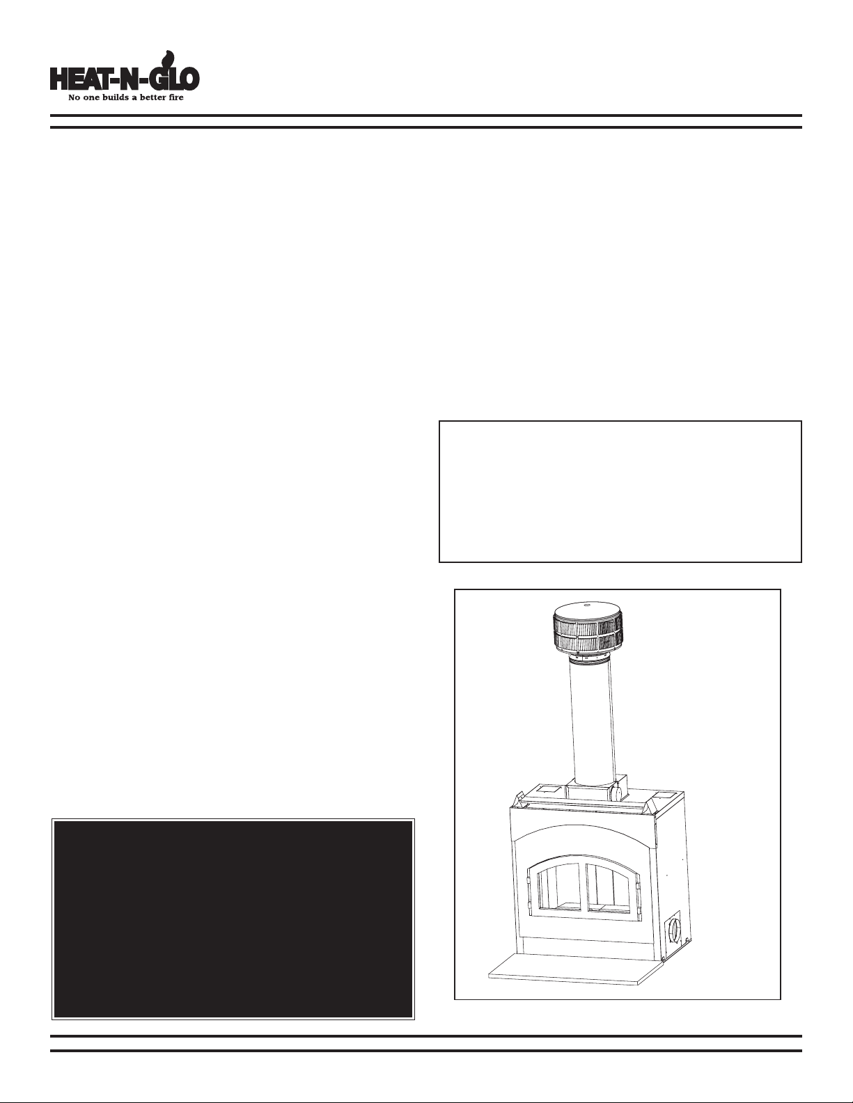
B. DESCRIPTION OF THE FIREPLACE
SYSTEM
1. The replace system consists of the following:
a. Fireplace
b. Firebrick
c. Chimney Termination Cap
d. Chimney System
e. Hearth Extension
f. Outside Air
2. Required Components Include:
a. Chimney Air Kit
3. Optional Components Include:
a. Fire Screen
b. Lintel Bar
c. Heat Zone Kit
NOTE: Illustrations used throughout these instructions
reect “typical installations” and are for design purposes
only. Actual installation may vary slightly due to individual
design preferences. However, minimum clearances must
be maintained at all times.
The illustrations and diagrams used throughout these
installation instructions are not drawn to scale.
Heat-N-Glo® is a registered trademark of Hearth & Home
Technologies, Division of HON INDUSTRIES.
WARNING!
This replace and its components are designed to be
installed and operated as a system. Any alteration to
or substitution for items in this system, unless allowed
by these installation instructions, will void the OMNI
Test Laboratories, Inc., listing and may void the product
warranty. It may also create a hazardous installation. Read
through these instructions thoroughly before starting
your installation and follow them carefully throughout
your project.
Figure 3A - Typical Fireplace System
4-03 3 480-1081
Page 4
North Star
Recommended
Location
Marginal
Location
Location
Not
Recommended
Recommended
Location
Location NOT
Recommended
Cathedral Ceiling Construction
2nd Floor
Balcony
1st Floor
Multi-level Roofs
EPA Certied Fireplace
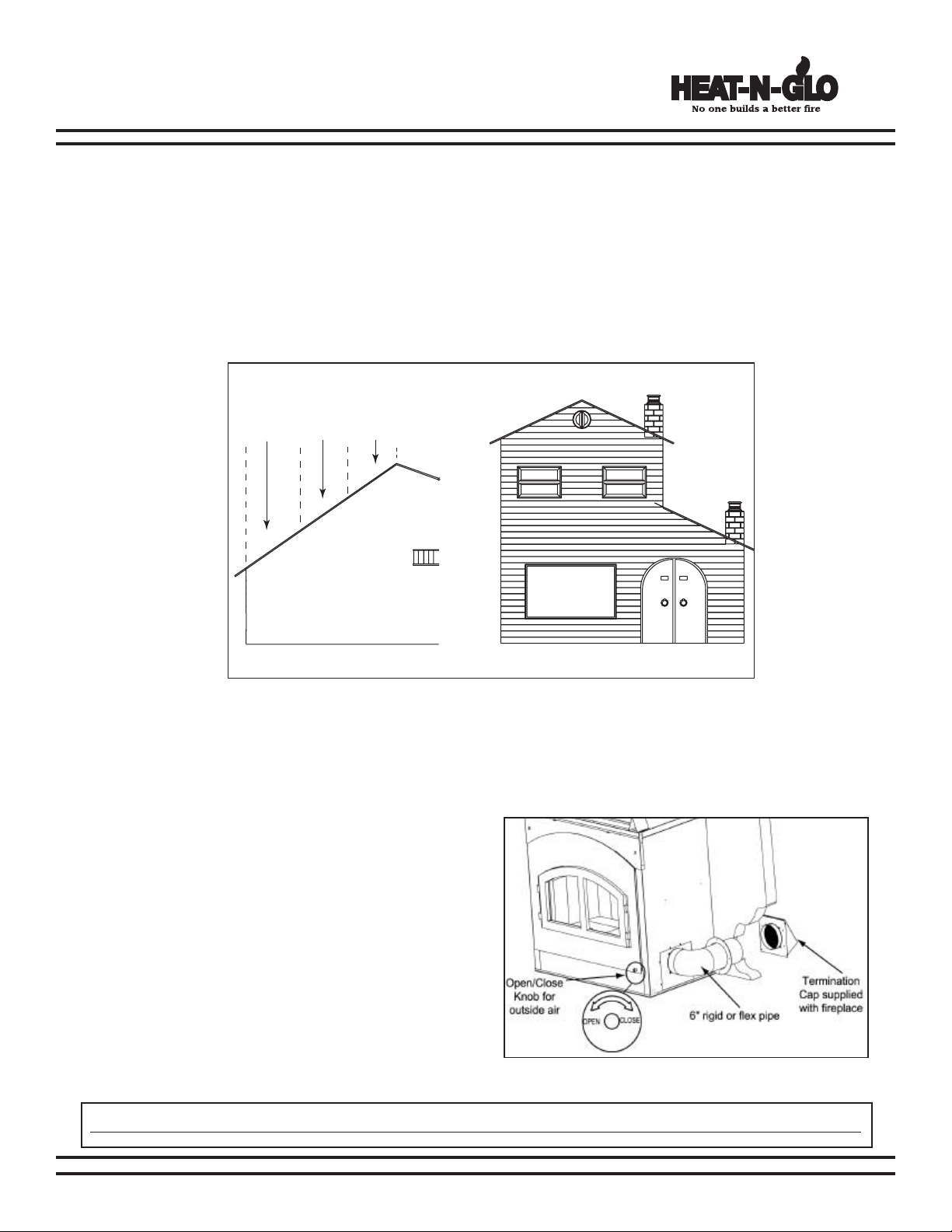
INSTALLATION AND DRAFT CONSIDERATIONS
The North Star Fireplace requires a minimum ue draft of -0.10 inches of water column on High, and -0.04 inches
of water column on Low, as measured with a draft meter. Most dealers have draft meters available to measure your
ue draft if you suspect a problem.
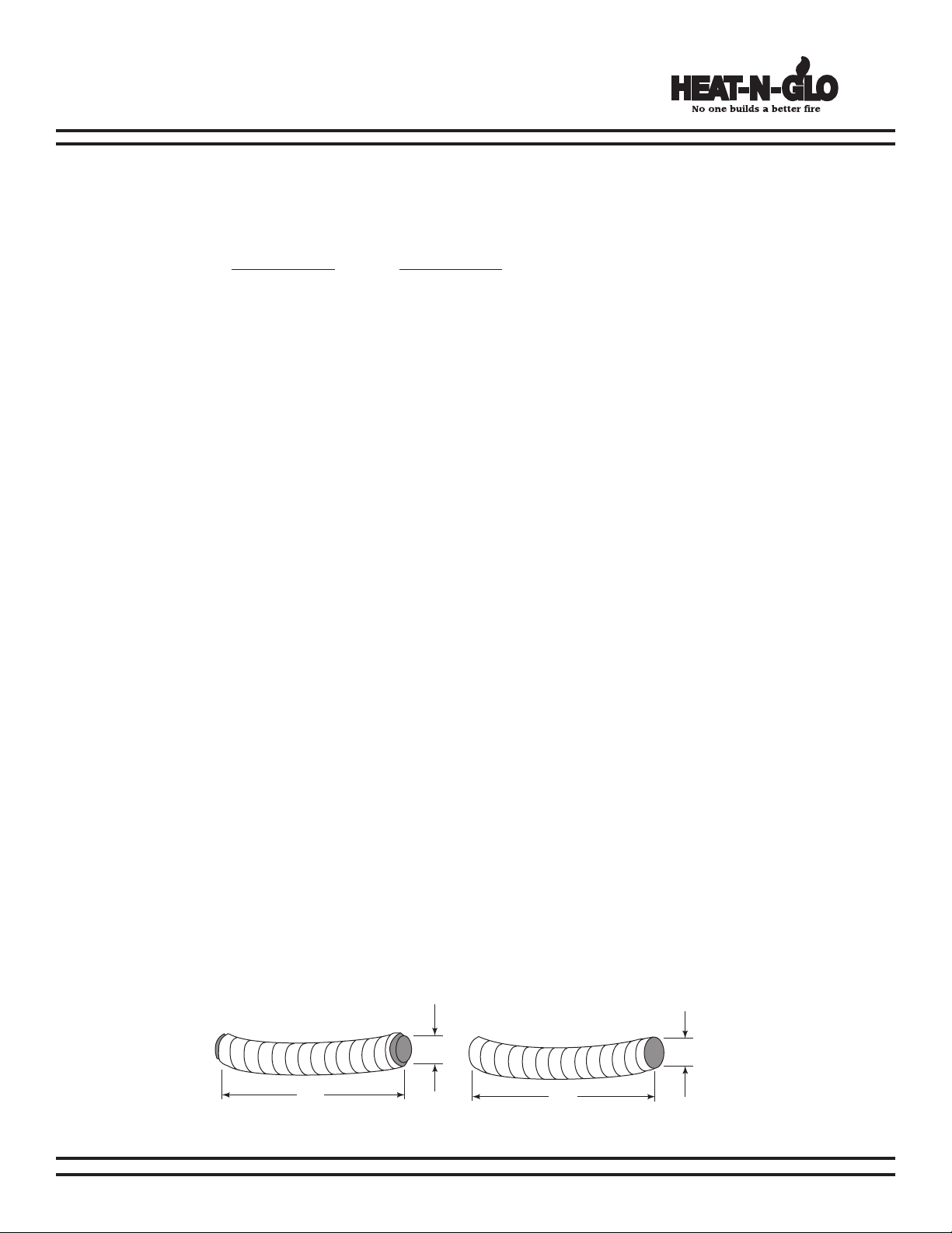
If the re is difcult to start, and smoke spills out of the door, or you nd it hard to establish and maintain a moderately high
burn rate, then the ue draft is too low and corrective measures must be taken.
OUTSIDE AIR KIT INSTALLATION
The outside air kit is installed on the right hand side of the replace.
1.
Cut a 6” hole in outside wall to accommodate outside air
piping.
2. Use 6” metal ex or rigid piping (not supplied) to directly
connect outside air to fireplace intake. Secure with hose
clamp.
3. Use the supplied termination cap with a rodent screen.
4. Seal between the wall and the pipe with silicone to prevent
moisture penetration.
NOTE: A control knob allows you control of the outside air inlet.
Use of outside air for combustion is required to conserve heated
air within the structure and to provide make up air to keep the
replace venting properly.
IMPORTANT!! OUTSIDE AIR MUST BE IN OPEN POSITION TO OPERATE FIREPLACE PROPERLY
480-1081 4 4-03
Page 5
North Star
23-1/8"
11-1/8"
9-11/16"
6-1/2"
5-7/8"
1"
Fan Electrical Access,
(right side of fireplace)
See Page 10
NONCOMBUSTIBLE
DECORATIVE MATERIAL
(2) HX4 MICORE FACTORY
BUILT HEARTH EXTENSION
(Each HX4 = 1/2" (13mm) thick)
HEARTH METAL STRIPS
GAP (SEAL WITH NONCOMBUSTIBLE SEALANT)
UP TO BOTTOM OF FASCIA
6" (152mm)
1" (51mm)
40-5/16"
31-1/8
"
37"
3-1/2"
40"
43-13/16"
EPA Certied Fireplace
FRONT VIEW
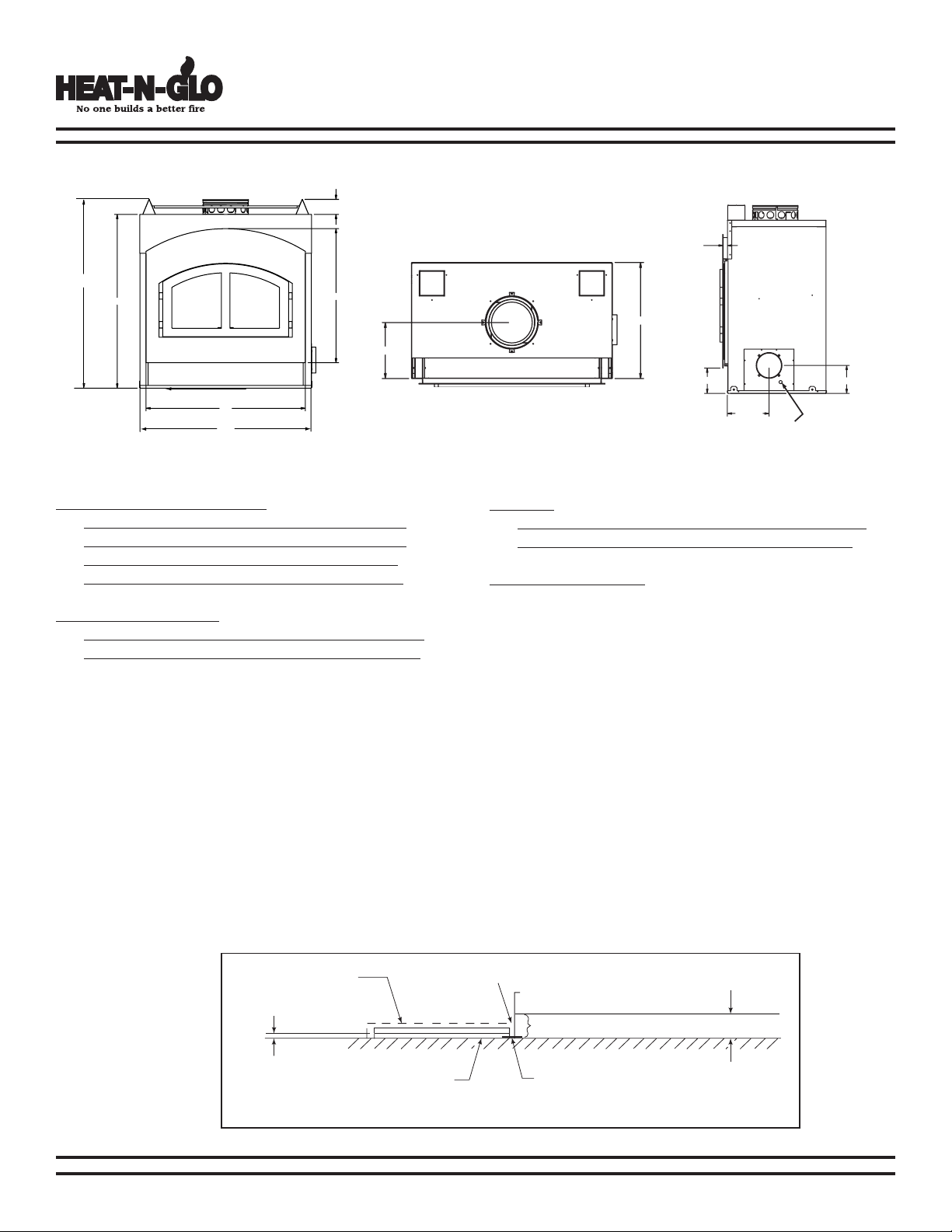
C. FIREPLACE DIMENSIONS
MINIMUM CLEARANCES TO COMBUSTIBLES
WITHIN ENCLOSURE AREA:
Appliance to backwall 1” (25mm)
Appliance to sidewall 1” (25mm)
Duct boots to framing 0” (0mm)
Top standoffs to header 0” (0mm”)
EXPOSED SURFACES
Faceplate to sidewall 16” (406mm)
Heat Zone air grills to ceiling 12”(305mm)
SIDE VIEW
TOP VIEW
MANTEL
Mantel from base of replace 60” (1524mm)
Maximum mantel width 12” (305mm
CHIMNEY SECTIONS
Chimney sections at any level require a 2” (51mm) minimum
air space clearance between the framing and chimney
section.
1. Fireplace and Hearth Extension are ush on the oor:
Combustible ooring 20” (508mm) in front of and 8” (203mm) to either side of the fuel opening; must be insulated with
non-combustible oor protection with a minimum thickness of 1” (25mm) and (“k” value = 0.43).
2. Fireplace is ush on the oor and Hearth Extension is raised to the bottom of the fascia:
Raised hearth must be constructed of non-combustible materials such as cement block or equivalent material Decorative
combustible ooring on the raised hearth must be 20” (508mm) in front of and 8” (203mm) to either side of the fuel
opening must be insulated with non-combustible floor protection with a minimum thickness of 1-1/2” (38mm) and
(“k” value = 0.43).
3. Fireplace is recessed in the oor to the bottom of the fascia:
Combustible ooring 30” (762mm) in front of and 8” (203mm) to either side of the fuel opening ;must be insulated with
non-combustible oor protection with a minimum thickness of 1” (25mm) and (“k” value = 0.43).
HEARTH EXTENSION / FLOOR PROTECTION
4-03 5 480-1081
Figure 5A - Factory Built Hearth Extension
Page 6
North Star
4"
42"
ID4
INSULATED DUCT
4
"
42"
UD4
UNINSULATED DUCT
EPA Certied Fireplace
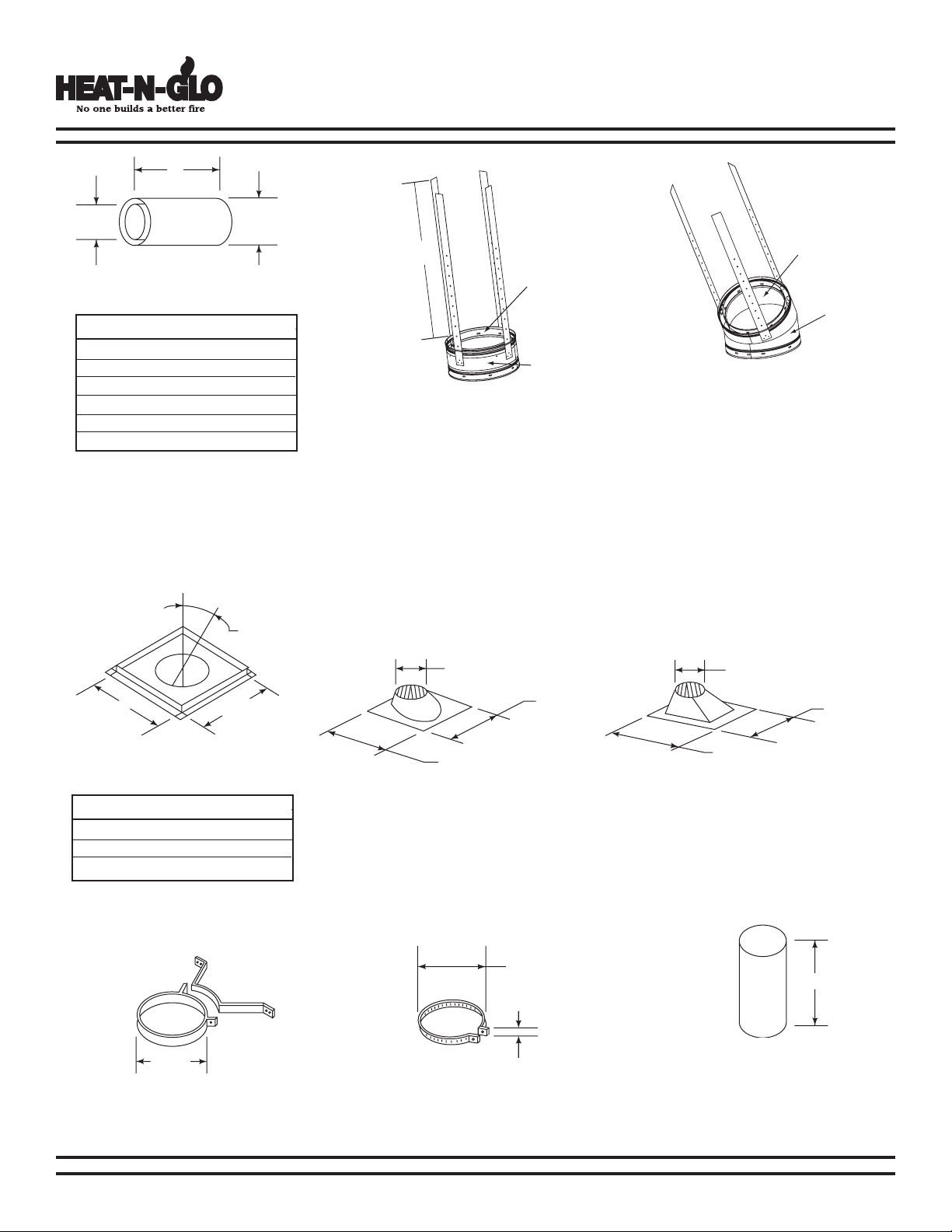
D. CHIMNEY COMPONENTS
The following pictures show the SL-300 Series chimney and replace components which may
be safely used with this replace.
Catalog No. Description
CAK4A Chimney Air Kit
ID4 Insulated Duct/Outside Air
UD4 Uninsulated Duct/Outside Air
SL306 Chimney Section - 6” long
SL312 Chimney Section - 12” long
SL318 Chimney Section - 18” long
SL324 Chimney Section - 24” long
SL336 Chimney Seciton - 36” long
SL348 Chimney Section - 48” long
SL3 Chimney Stabilizer
SL315 Chimney Offset/Return - 15°
SL330 Chimney Offset/Return - 30°
FS338 Firestop - Straight
FS339 Firestop - 15°
FS340 Firestop - 30°
AS8 Straight Attic Insulation Shield
JB877 Chimney Joint Band
CB876 Chimney Bracket
RF370 Roof Flashing - Flat to 6/12 Pitch
RF371 Roof Flashing - 6/12 to 12/12 Pitch
TR344 Round Termination Cap
TR342 Round Telescoping Termination Cap
ST375 Square Termination Cap
TS345 Square Termination Cap
CT35 Chase Top
MH842 Mobile Home Thimble
MH841 Mobile Home Thimble Extension, 20”
HX4 MICORE Hearth Extension, 20” wide
Mesh-HHT Fire Screen
HHT-Template Metal Face Template
HeatZone-Wood Heat Zone Kit
LintelBar-HHT Lintel Bar
480-1081 6 4-03
Page 7
Chimney Sections
24"
A
8" 101/2"
Inside
Diameter
8"
Outside
Diameter
10"
A
B
14-1/2"
10-1/2"
2"
10-1/2"
12"
24-5/8"
27-3/8"
12"
31"
24-5/8"
Inside
Diameter
8"
Outside
Diameter
10"
20-3/4"
Catalog No. A B
SL306 6” 4-3/4”
SL312 12” 10-3/4”
SL318 18” 16-3/4”
SL324 24” 22-3/4”
SL336 36” 34-3/4”
SL348 48” 46-3/4”
A = Actual Length
B = Effective length (length of
chimney part after it has been
snapped to another)
SL3 - Chimney Stabilizer
North Star
EPA Certied Fireplace
SL315-330 - Offset/Return
Firestop Spacer
Catalog No. A B
FS338 0° 14-1/2”
FS339 15° 18-3/8”
FS340 30° 16-3/4”
4-03 7 480-1081
Chimney Bracket
CB876
RF370 - Roof Flashing
Flat to 6/12 Pitch
JB877
Joint Band
RF371 - Roof Flashing
6/12 to 12/12 Pitch
AS8
Straight Attic
Insulation Shield
Page 8
North Star
10-1/2"
12"
12"
5-1/4"
4"
TR342
TERMINATION CAP
TOP OF
UPPERMOST
CHIMNEY
SECTION
14-1/2"
MAX.
DISTANCE
CHASE TOP
23"
14-3/4"
17-3/4"
(8" Flue)
(10-1/2" Outer)
16-1/2"
13-1/4"
22-1/4"
23-1/2"
72" 36"
2"
10-7/8"
24-5/8"
16-5/8"
16-5/8"29"
EPA Certied Fireplace
TS345/TS345P
Square Termination Cap
ST375
Square Termination Cap
MH841
Mobile Home Thimble
Extension 20”
MH842
Mobile Home Thimble
TR344
Round Termination Cap
TR342
Round Telescoping
Termination Cap
Chase Top
480-1081 8 4-03
CT35
CAK4A
Chimney Air Kit
Page 9
North Star
88-7/8"
44-7/16"
23-5/8"
62-13/16"
42"
51"
23-1/2"
10"
As a room
divider
A
long a wall
In an exterior chase or
projecting into a garage
Across a corner
EPA Certied Fireplace
E. PRE-INSTALLATION PREPARATION
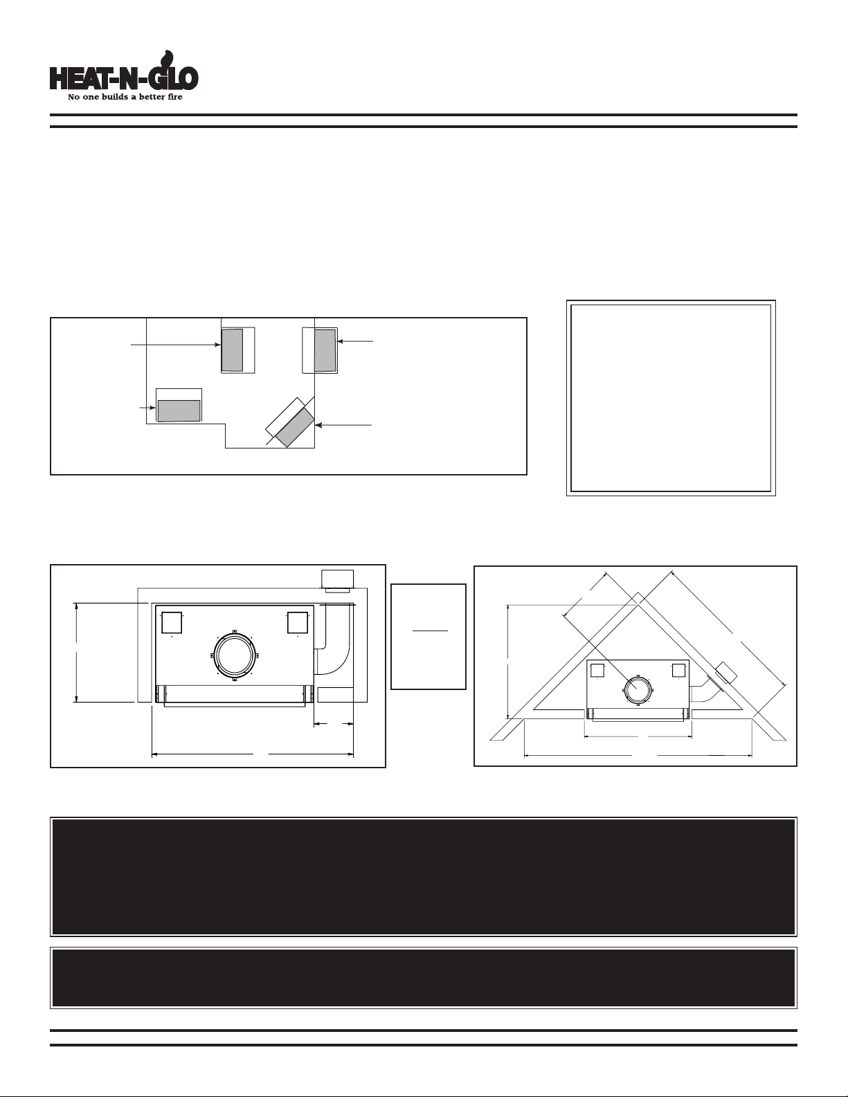
1. Fireplace Locations and Space Requirements
Several options are available to you when choosing a location for your replace. This replace may be used as a room divider,
installed along a wall, across a corner or used in an exterior chase. See Figure 9A.
Locating the replace in a basement, near frequently opened doors, central heat outlets or returns, or other locations of considerable
air movement can affect the performance and cause intermittent smoke spillage from the front of the replace when no outside
air is used. Outside air is required for combustion. (see page 21). The North Star Fireplace comes equipped with an outside
air inlet to feed combustion air from outside the home, along with an outside air termination cap. Consideration should be given
to these factors before deciding on a location.
CLEARANCES!
A minimum 1” air clearance must
be maintained at the back and
sides of the replace assembly.
Chimney sections at any level
require a 2” minimum air space
clearance between the framing
and chimney section.
Figure 9A - Fireplace Locations
Figures 9B and 9C show two typical installations for the outside air kit. Allowances must be made for 90° bends. Less
space is required when ducting goes directly outside without forming elbows.
These are
rough
framing
dimensions
only.
Figure 9B
Installation Along a Wall or an Exterior Chase
Figure 9C
Corner Installation
WARNING! Do not draw outside air from garage spaces. Exhaust products of gasoline engines are hazardous.
Do not install outside air ducts such that the air may be drawn from attic spaces, basements or above the roong where
other heating appliances or fans and chimneys exhaust or utilize air. These precautions will reduce the possibility of
replace smoking or air ow reversal. The outside air inlet must remain clear of leaves, debris ice and/or snow. It must be
unrestricted while unit is in use to prevent room air starvation which can cause smoke spillage and an inability to maintain
a re. Smoke spillage can also set off smoke alarms.
WARNING! To prevent contact with sagging or loose insulation, the replace must not be installed against vapor barriers
or exposed insulation. Localized overheating could occur and a re could result.
4-03 9 480-1081
Page 10
North Star
43-7/8"
42"
2"
24"
14-2 w/ground
Standard wall mount with
Junction Box
14-3 w/ground
WIRE NUT
WHITE
GREEN
BLACK
BLACK
RED
WHITE
Match colors to wire
harness (red to red,
white to white, etc) and
secure with a wire nut
EPA Certied Fireplace
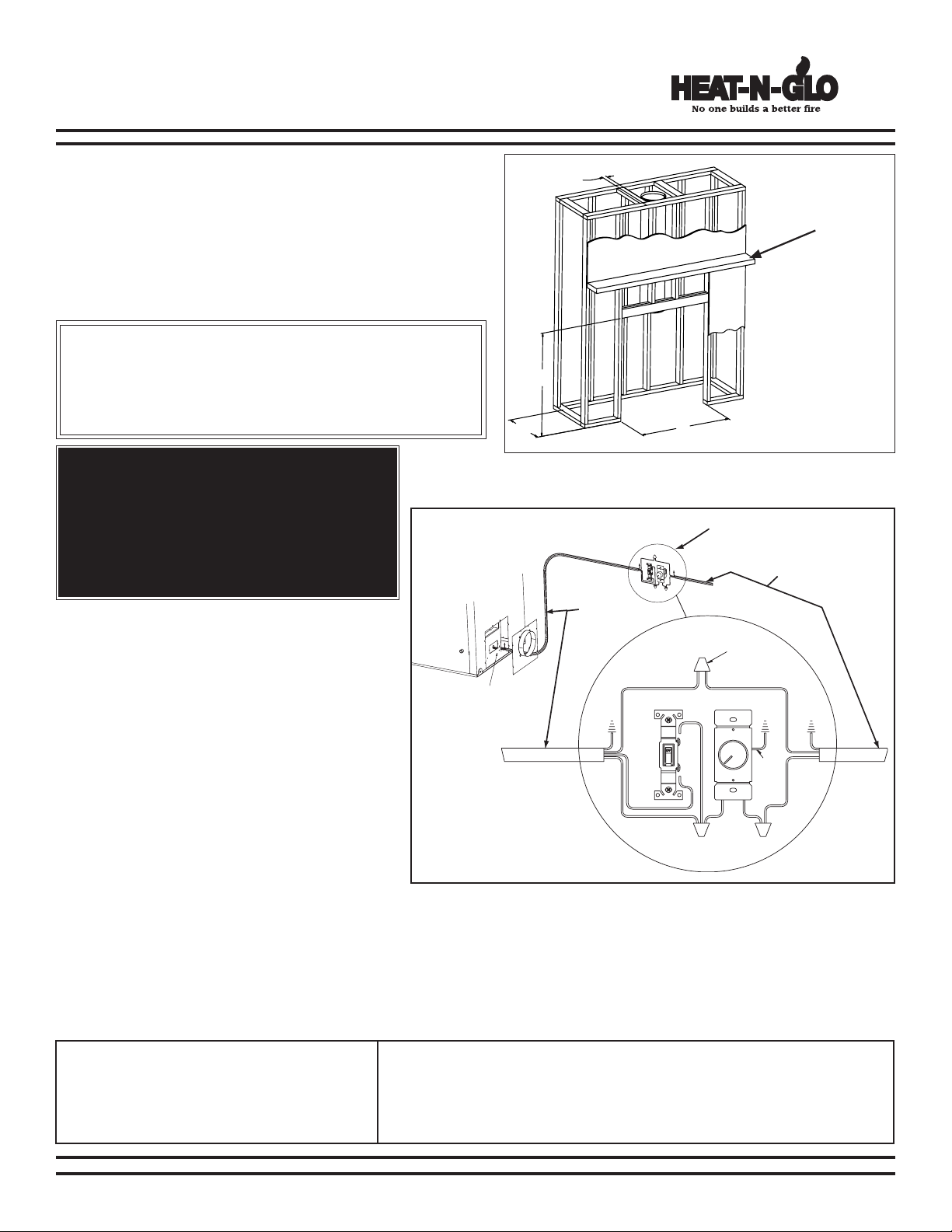
2. Framing the Fireplace
The North Star Fireplace will t the framed opening width of
43-7/8” tall. The nished cavity depth must be no less than 24”.
Framing must extend straight up all the way to the ceiling.
Figure 10A shows a typical framing (using 2 x 4 lumber) of the
replace, assuming combustible materials are used. All required
clearances to combustibles around the replace must be adhered
to. Any framing across the top of the replace must be above
the level of the top standoffs.
CLEARANCES!
A minimum 1” air clearance must be maintained at the back and sides
of the replace assembly.
Chimney sections at any level requ ire a 2” minimum air spac e
clearance between the framing and chimney section.
WARNING!
Do not apply combustible nishing materials over
any part of the front of this replace or a structure
re may result. The metal replace face may only
be covered with noncombustible materials such
as ceramic tile, brick, or stone. Do not cover or
block any cooling air slots.
Position mantel
60” from base of
the replace
Figure 10A- Framing the Fireplace
3. Electrical Access and Wiring Diagram
NOTE: The manual override switch, rheostat speed
control and cover plate are supplied. You will need to
supply: 14-3 wire with ground; 14-2 wire with ground;
standard wall mount junction box; wire nuts.
1. Remove outside air cover plate on the bottom
2. Thread the 14-3 with ground wire through the
3. Match colors to wire harness, (red to red, white
NOTE: Wiring for blowers must be done before
framed enclosure is completed. If using a
Heat Zone kit, it also must be installed before
enclosure is complete.
When planning your fireplace location, the chimney construction and necessary clearances must be considered. The fireplace
system and chimney components have been tested to provide exibility in construction. The following gures are the minimum
distances from the base of the replace.
1. Min overall straight height 13 ft.
2. Min height with offset/return 14.5 ft.
3. Max height 50 ft.
4. Max chimney length between
480-1081 10 4-03
right side of the replace.
opening with the strain relief on the cover plate.
to white, etc) and secure with wire nuts.
an offset and return
F. CHIMNEY REQUIREMENTS
12 ft.
Figure 10B- Fan Wiring Diagram
5. Maximum distance between chimney stabilizers 35 ft.
6. Double offset/return minimum height 20 ft.
7.
Maximum unsupported chimney length between the offset and return
8.
Maximum straight unsupported chimney height above the replace
6 ft.
35 ft.
Page 11
North Star
A
B
1-1/4" OVERLAP
EPA Certied Fireplace
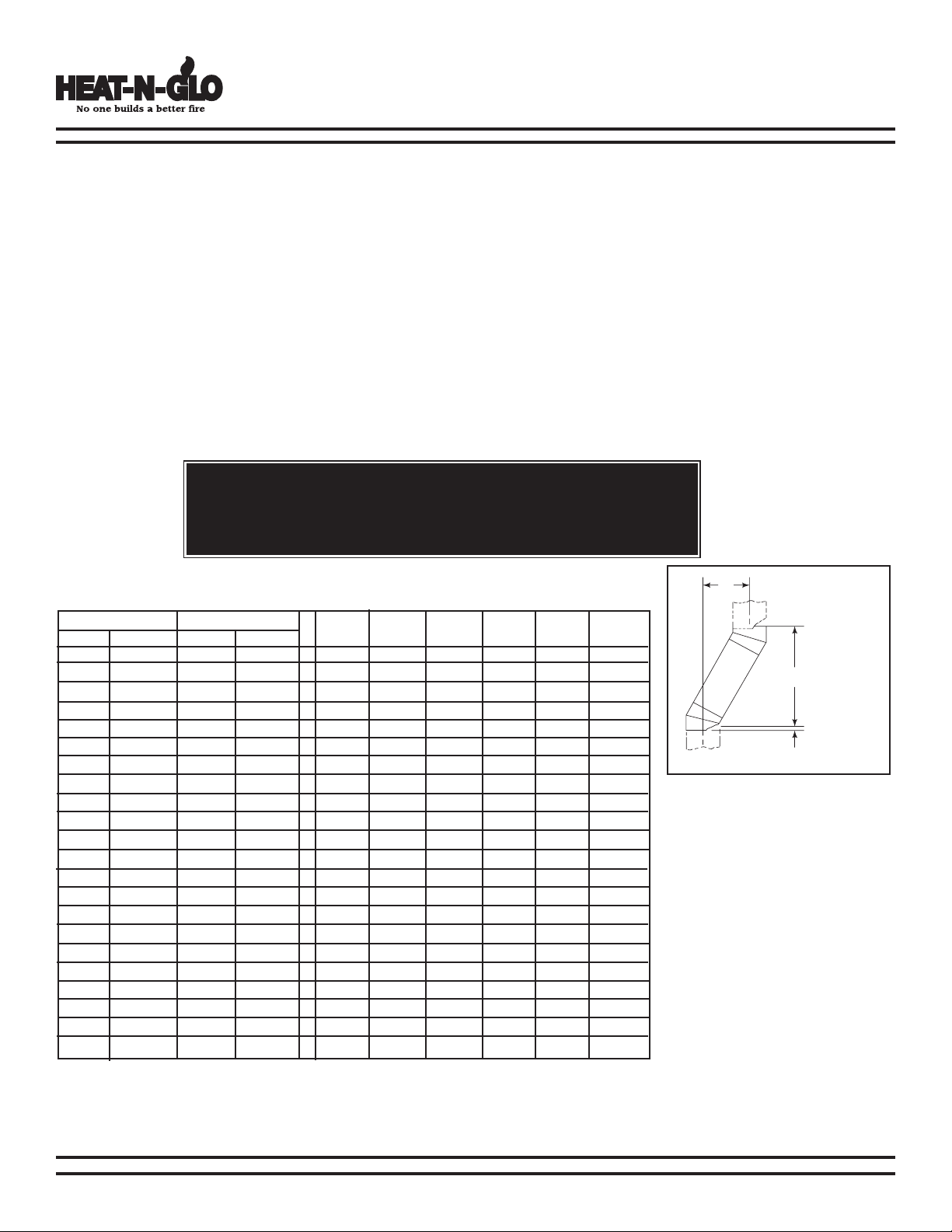
1. Using Offsets and Returns
a. To bypass any overhead obstructions, the chimney may be offset using a 15° or a 30° offset/return. Perform the following steps
to determine the correct chimney component combination for your particular installation.
b. An offset and return may be attached together or a chimney section(s) may be used between an offset and return.
1) Measure how far the chimney needs to be shifted to enable it to avoid the overhead obstacle. See Figure 11A, dimension
“A” to determine chimney sections required to achieve the needed shift.
2) After determining the offset dimension, refer to Table 1 and nd the “A” dimension closest to but not less than the
distance of shift needed for your installation.
3) The “B” dimension that coincides with the “A” dimension represents the required vertical clearance that is needed
to complete the offset and return.
4) Read across the chart and nd the number of chimney sections required and the model number of those particular
chimney parts.
5) Whenever the chimney penetrates a oor/ceiling, a restop spacer must be installed.
6) The effective height of the replace assembly is measured from the base of replace to top of starter collar.
WARNING!
Do not combine offsets to create an offset greater than 30° from vertical. This
may create a re hazard since the natural draft may be restricted.
Table 1 Offset Chart*
15° 30°
A B A B
1-5/8” 13-3/8” 3-7/8” 14-1/2” - - - - - --
2-7/8” 17-3/4” 6-1/4” 18-5/8” 1 - - - - --
- - 8-5/8” 22-3/4” 2 - - - - --
4-1/2” 23-5/8” 9-1/4” 23-3/4” - 1 - - - --
- - 11-5/8” 27-7/8” 1 1 - - - --
6” 29-3/8” 12-1/4” 29” - - 1 - - --
7-1/4” 34” 14-5/8” 33” - 2 - - - --
- - 15-1/4” 34-1/8” - - 2 1 - --
- - 17-5/8” 38-1/4” 1 - - 1 - -
- - 20-5/8” 43-1/2” - - - - - --
10-5/8” 46-3/4” 21-1/4” 44-5/8” - - - - 1 -
11-7/8” 51-3/8” 23-5/8” 48-3/8” 1 - - - 1 -
- - 26-5/8” 53-7/8” - - - 2 - -
13-3/4” 58-3/8” 27-1/4” 55-3/4” - - - - - -
15” 63” 29-5/8” 59” 1 - - - - 1
16-1/2” 68-3/4” 32-5/8” 64-1/4” - 1 - - - 1
18” 74-5/8” 35-5/8” 69-1/2” - - 1 - - 1
- - 38-5/8” 74-5/8” - - - 1 - 1
- - 41” 78-3/4” 1 - - 1 - 1
22-3/4” 91-7/8” 44-5/8” 85” - - - - 1 1
24” 96-1/2” 47” 89-1/8” 1 - - - 1 1
25” 103-1/2” 50-5/8” 95-1/2” - - - - - 2
SL306 SL312 SL318 SL324 SL336 SL348
Figure 11A - Chimney Offset/
Return
Example: Your “A” dimension
from Figure 11A is 14-1/2”.
Using Table 1 the dimension
closest to, but not less than
14-1/2” is 14-5//8” using a 30°
offset/return. It is then determined from the table that you
would need 33” (Dimension
“B”) between the offset and
return. The c himney compone nts that bes t fit your
application are two SL312s.
*Proper assembly of air cooled chimney parts result in an overlap at
chimney joints of 1-1/4”. Effective length is built into this chart.
4-03 11 480-1081
Page 12

North Star
THEN
BUT
MUST BE AT
LEAST 2 FEET
NEVER LESS
THAN 3 FEET
I
F 10
FEET OR
LESS
EPA Certied Fireplace
2. Chimney Height Requirements (above roof
line)
a. Major building codes specify a minimum chimney
height above the roof top. These specications are
summarized in what is known as the Ten Foot Rule.
This rule states:
If the horizontal distance from the side of the
chimney to the peak of the roof is 10 feet or less, the
top of the chimney must be at least 2 feet above
the peak of the roof, but never less than 3 feet
in overall height above the highest point where it
passes through the roof.
If the horizontal distance from the side of the
chimney to the peak of the roof is more than 10 feet,
a chimney height reference point is established on
the surface of the roof a distance of 10 feet from the
side of the chimney in a horizontal plane. The top
of the chimney must be at least 2 feet above this
reference point, but never less than 3 feet in height
above the highest point where it passes through the
roof. See Figure 12A.
b. These chimney heights are necessary in the interest
of safety but do not ensure smoke-free operation.
Trees, buildings, adjoining roof lines, adverse wind
conditions, etc. may create a need for a taller
chimney should smoking occur.
Figure 12A- Chimney Height
3. Number of Sections Required
To determine the chimney components needed to
complete your particular installation, follow the steps
below:
a. Determine the total vertical height of the replace
installation. This dimension is measured from the
base of the replace assembly to the point where
the smoke exits the termination cap.
b. Subtract the effective height of the replace assembly
from the overall height of the replace installation
(measured from the base of the replace to the
bottom of the termination cap).
c. Refer to Table 2 to determine what components must
be selected to complete the replace installation.
d. Determine the number of restop spacers, stabiliz-
ers, roof ashing, etc. required to complete the
replace installation.
Table 2
HEIGHT OF CHIMNEY COMPONENTS
Chimney Stabilizer
SL3 4-3/4”
Firestop Spacers
FS338 0”
FS339 0”
FS340 0”
Offsets/Returns
SL315 13-3/8”
SL330 14-1/2”
Roof Flashing
RF370 0
RF371 0
Chimney Sections*
SL306 4-3/4”
SL312 10-3/4”
SL318 16-3/4”
SL324 22-3/4”
SL336 34-3/4”
SL348 46-3/4”
*Dimensions reect effective height.
480-1081 12 4-03
Page 13

North Star
1" OVERLAP
Metal strips 2" under edge of
Fireplace and Hearth Extension and
2" on both side of fireplace opening
EPA Certied Fireplace
G. INSTALLATION OF FIREPLACE
WARNING!
Before starting, do the following:
1. Wear gloves and safety glasses for protection.
2. Keep hand tools in good condition. Sharpen cutting edges and make sure tool handles are secure.
3. Always maintain the minimum air space required to the enclosure to prevent re.
1. Positioning the Fireplace
This fireplace may be placed on either a combustible or
noncombustible continuous at surface, depending on the type
of installation. Follow the instructions for framing on pages
9-10 and Hearth Extension/Floor Protection Requirements
under Minimum Clearances to Combustibles on page 5.
Slide the fireplace into position. Be sure to provide the
minimum 1” air clearance at the sides and back of the
replace assembly.
2. Placing the Protective Metal Hearth Strips
Included with your replace you will nd two metal hearth
strips measuring approximately 23” x 4”. These strips are
used to provide added protection where the replace and the
hearth extension meet.
Slide each metal strip 2” under the front edge of the replace.
The individual pieces must overlap each other by 1” minimum
in the middle of the replace to provide continuous coverage
of the oor. See Figure 13A. These metal strips should extend
from the front and sides of the replace opening by 2”.
3. Leveling the Fireplace
L
evel the replace side-to-side and front-to-back. Shim with
noncombustible material, such as sheet metal, as necessary.
Secure the replace (using the pallet mounting brackets located
on either side of the replace) to the oor.
Figure 13A - Positioning the Metal Strips
4. Assembling Chimney Sections
Attach either a straight chimney section or an offset to the top
of the replace (depending on your installation requirement).
Chimney sections are locked together by pushing downward
until the top section meets the stop bead on the lower
section.
The inner ue is placed to the inside of the ue section below
it. The outer casing is placed outside the outer casing of the
chimney section below it. See Figure 13B.
NOTE: Chimney Air Kit, Part CAK4A is required.
Follow instructions supplied with the kit.
WARNING!
Carefully follow the instructions for assembly of the
pipe and other parts needed to install this fireplace
system. Failure to do so may result in a re, especially
if combustibles are too close to the replace or chimney
and air spaces are blocked, preventing the free movement
of cooling air.
4-03 13 480-1081
Figure 13B-Assembling Chimney Sections
CAUTION:
Inner ue and outer liner sections cannot be disassembled
once locked together. Plan ahead to ensure the proper
installation height is achieved with the selected chimney
components.
Page 14

North Star
ROOM ABOVE
A
TTIC ABOVE
24"
AS8 ATTIC
INSULATION
SHIELD
FS338
FIRESTOP
SPACER
CHIMNEY
IN
SULATION
10-1/2"
14-1/2"
EPA Certied Fireplace
5. Installing Firestop Spacers
Mark and cut out an opening in the ceiling for the restop
spacer being utilized (14-1/2” x 14-1/2” for an FS338, 14-1/2”
x 18-3/8” for an FS339 and 14-1/2” x 23” for an FS340).
Frame the opening with the same dimension lumber used
in the ceiling joists.
Install the restop spacer.
These restop spacers are designed to provide the minimum
2” air space required around the chimney. In all situations, the
restop spacers are to be nailed to the ceiling joists from the
bottom or replace side, EXCEPT when the space above is
an insulated ceiling or attic space. In this situation, the restop
spacer must be nailed from the top side to prevent loose
insulation from falling into the required 2” air space around the
chimney. See Figure 14A.
6. Attic Insulation Shield
An insulation shield should be installed when there is a
possibility of insulation coming into contact with the factory
built chimney system. The insulation shield is installed by
positioning it over the vertical chimney section where it
penetrates a restop spacer. The restop spacer will support
the insulation shield. See Figure 14B.
7. Double-checking the Chimney Assembly
Continue assembling the chimney sections up through the
restop spacers as needed. While doing so, be aware of the
height and unsupported chimney length limitations that are
given on page 10 under “Chimney Requirements”.
Check each section by pulling up slightly from the top to
ensure proper engagement before installing the succeeding
sections. If they have been connected correctly, they will not
disengage when tested.
CAUTION:
Firestop spacers must be used whenever the
chimney penetrates a ceiling/oor area.
Figure 14A
Installing the Firestop Spacer
Figure 14B
Installing an Attic Insulation Shield
480-1081 14 4-03
NOTE: Wiring for blowers must be done before
framed enclosure is completed. If using a Heat
Zone kit, it also must be installed before enclosure
is complete.
Page 15

North Star
CHIMNEY
FLASHING
PLATE
JOISTS
NAIL
THIMBLE
FLASHING
FLASHING
CHIMNEY
FLASHING
PLATE
NAIL
THIMBLE
SCREW
THIMBLE
EXTENSION
EPA Certied Fireplace
8. Mobile home installation
You must use the outside air termnination cap supplied
with your North Star Fireplace for installation in a
mobile home. If you use an alternative material it must
be designed to prevent material from dropping into the
area beneath the mobile home, and to prevent rodents
from enterting from the outside.
1. An outside air inlet must be provided for combustion and must
remain clear of leaves, debris, ice and/or snow. It must be
unrestricted while unit is in use to prevent room air starvation
which can cause smoke spillage and an inability to maintain a
re. Smoke spillage can also set off smoke alarms.
2. The replace is to be secured to the mobile home structure.
Use same holes that attached the replace to the pallet to
secure it to the oor use 1/4” x 2” lag bolts or equivalent.
3. Unit must be grounded with #8 solid copper grounding wire or
equivalent and terminated at each end with N.E.C. approved
grounding device.
4.
Refer to Minimum Clearances to Combustibles on page 5 and
chimney components on pages 6-8.
5. Floor protections requirements on page 17 must be followed
precisely.
6. Use silicone to create an effective vapor barrier at the location
where the chimney or other component penetrates to the
exterior of the structure.
7.
Follow the chimney and chimney connector manufacturer’s
instructions when installing the ue system for use in a mobile
home.
9. SL-300 Series MH842 Celing/Roof Thimble
1. Locate the point where the chimney will exit the roof by
plumbing down to the center of the chimney. Lay out, cut and
frame a 14-1/2” square opening (measured on the horizontal)
through the ceiling and roof structure. See Chapter 25 of the
Uniform Building Code for Framing Details.
2. The thimble must extend completely through the roof structure
shielding combustible materials. Five location holes have been
provided to allow for a variety of ceiling/roof thicknesses. The
MH841 Thimble Extension is required when the ceiling/roof
thickness exceeds 12-1/2”. The extension should overlap
the thimble one inch.
3. To attach the extension to the thimble, drill 1/8” holes through
the outer shield of the thimble using the predrilled holes in the
extension as guides. Attach the extension to the thimble using
the screws provided with the extension.
4. Install the thimble assembly and nail it securely to the framing
members.
5. Center the ashing over the chimney and nail it to the roof
using the Stormguard nails provided. Keep gaps between the
ashing plate and the roof to a minimum.
6. Caulk the flashing plate and roof junction as well as the
vertical seam on the ashing. All nail heads must be caulked
with a roong sealant.
7. Finish assembling the chimney storm collar and termination
cap following the installation instructions provided with
them.
NOTE: Top sections of chimney must be removable to allow
maximum clearance of 13.5’ (411cm) from ground level for
transportation purposes.
8. Burn wood only. Other types of fuels may generate poisonous
gases (e.g., carbon monoxide).
WARNING!
NEVER DRAW COMBUSTION AIR FROM A WALL,
FLOOR OR CEILING CAVITY OR FROM ANY
ENCLOSED SPACE SUCH AS AN ATTIC OR GARAGE.
WARNING!
DO NOT INSTALL IN SLEEPING ROOM.
CAUTION:
The structural integrity of the mobile home oor, wall and
ceiling/roof must be maintaned. (i.e., Do not cut through
oor joist, wall stud, ceiling truss, etc.)
Figure 15A - Installing an MH842, Conguration 1
Figure 15A - Installing an MH842, Conguration 2
4-03 15 480-1081
Page 16

North Star
FIRESTOP
JOINT BAND
(OPTIONAL)
STRAPS
OPTIONAL
ADDITIONAL
SUPPORT
NAIL
FLASHING
PLATE
CHIMNEY
THIMBLE
EXTENSION
SCREW
FLASHING
THIMBLE
A
DJUSTABLE
EXTENSION
HOLES
EPA Certied Fireplace
9. SL-300 MH842 Celing/Roof Thimble (Cont’d)
Figure 16A - Installing an MH842 Conguration 3
10 Securing the Chimney System
When offsets and returns are joined to straight pipe sections,
they must be locked into position with the screws provided
(outer only), using the predrilled holes. To prevent gravity
from pulling the chimney sections apart, the returns and the
chimney stabilizers have straps for securing these parts to
joists or rafters. See Figure 16B.
11.Marking the Exit Point of the Roof
Locate the point where the chimney will exit the roof by
plumbing down to the center of the chimney. Drive a nail up
through the roof to mark the center. See Figure 16C.
12.Cutting out the Hole in the Roof
Measur e to either side of the nail 7-1/4” a nd mark the
14-1/2” x 14-1/2” opening required. This is measured on the
horizontal; actual length may be larger depending on the pitch
of the roof. Cut out and frame the opening. See Chapter 25 of
the Uniform Building Code for Roof Framing Details.
Be sure to maintain a 2” minimum air space between the
chimney section and the roof.
13.Assembling the Chimney Sections
Through the Roof
Continue to add chimney sections through the roof opening,
maintaining at least a 2” air space.
NOTE: You must provide support for the pipe during construction
and check to be sure inadvertent loading has not dislodged the
chimney section from the replace or at any chimney joint.
Figure 16B - Offset/Return with Stabilizer
Maintain a minimum of 2” air clearance to all parts of the
chimney system at all times! Failure to maintain this 2” air
clearance will cause a structure re.
WARNING!
Figure 16C - Ceiling/Attic Construction
WARNING!
When chimney sections exceeding six feet in length
are installed between an offset and return, structural
support must be provided to reduce off-center loading
and prevent chimney sections from separating at the
chimney joints.
480-1081 16 4-03
Page 17

North Star
NONCOMBUSTIBLE
DECORATIVE MATERIAL
(2) HX4 MICORE FACTORY
BUILT HEARTH EXTENSION
(Each HX4 = 1/2" (13mm) thick)
HEARTH METAL STRIPS
GAP (SEAL WITH NONCOMBUSTIBLE SEALANT)
UP TO BOTTOM OF FASCIA
6" (152mm)
1" (51mm)
20"
8" from each side of
fuel loading door
41"
EPA Certied Fireplace
14.Installing the Roof Flashing
If a roof ashing is to be used, install the roof ashing
appropriate to the roof pitch and install a round termination
A minimum 1” air clearance must be maintained at
the back and sides of the replace assembly.
CLEARANCES!
cap following the instructions shipped with the cap.
For chase installations you can use a round termination
cap (TR344), a round telescoping termination cap (TR342)
or a square termination cap (ST375). A chase installation
Chimney sections at any level require a 2” minimum
air space clearance between the framing and
chimney section.
must use a chase top. Chase tops are available from your
dealer. See page 19 for building a chase.
NOTE: Use only a noncombustible material to nish the
face of the replace below the level of the front standoffs.
15.Completion of the Enclosure
Complete the fireplace enclosure, allowing space for
outside air ducts. Electrical wiring should not come in
A noncombustible material such as USG MICORE CV230
Mineral Fiber Board, or USG DUROCK Cement Board is
recommended for this purpose.
contact with the replace. A minimum clearance of 1”
must be maintained between the replace sides and
back and the enclosure. See pages 9-10 for framing
details.
16.Hearth Extension
A hearth extension must be installed with all replaces to
protect the combustible oor in front of the replace from
both radiant heat and sparks.
The construction of, and materials used for a hearth
extension are shown in Figures 17A and 17B. A hearth
extension of this construction may be covered with any
noncombustible decorative material and may have a
maximum thickness as per the illustration. Seal gaps
between the hearth extension and the front of the replace
with a bead of noncombustible sealant.
Figure 17A-Field Construction Hearth Extensions
1. Hearth Extension & Floor Protection ush on the oor.
Combustible ooring 20” in front of and 8” to either side of the fuel opening; must be insulated with non-combustible oor
protection with a minimum thickness of 1” (“k” value = 0.43). Use Alternate Material Worksheet on page 18 to determine
the “k” value of the alternative material..
2. Fireplace is ush on the oor and Hearth Extension is raised to the bottom of the fascia:
Raised hearth must be constructed of non-combustible materials such as cement block or equivalent material Decorative
combustible ooring on the raised hearth must be 20” (508mm) in front of and 8” (203mm) to either side of the fuel opening must be
insulated with non-combustible oor protection with a minimum thickness of 1-1/2” (38mm) and (“k” value = 0.43).
3. Fireplace is recessed in the oor to the bottom of the fascia:
Combustible ooring 30” (762mm) in front of and 8” (203mm) to either side of the fuel opening; must be insulated with
non-combustible oor protection with a minimum thickness of 1” (25mm) and (“k” value = 0.43).
4-03 17 480-1081
Figure 17B - Factory Built Hearth Extension
Page 18

North Star
Seal with noncombustible sealant
=
1
.84
R =
x T
1
k
x 0.75 = 0.893
R
brick
= 0.2 x 4 = 0.431
4" brick of r = 0.2, therefore:
1/8" mineral board of k = 0.29, therefore:
R
mineral board
=
1
0.29
x 0.125 = 0.431
R
total
= R
brick
+ R
mineral board
= 0.8 + 0.431 = 1.231
1
k
Btu(in)
ft2(hr)(oF)
= K x 12
(ft2)(hr)(oF)
Btu
k =
K =
r =
(ft2)(hr)(oF)
(Btu)(in)
=
Btu(ft)
ft2(hr)(oF)
R =
x T
1
k
R =
x T
1
K x 12
EPA Certied Fireplace
17. Alternate materials worksheet
How to determine if alternate oor protection materials are acceptable:
All oor protection must be non-combustible (i.e., metals, brick, stone, mineral ber boards, etc.). Any organic materials (i.e., plastics, wood paper
products, etc.) are combustible and must not be used. The oor protection specied includes some form of thermal designation such as R-value
(thermal resistance) or k-factor (thermal conductivity).
PROCEDURE:
1. Convert specication to R-value:
R-value given - no conversion needed.
k-factor is given with a required thickness (T) in inches:
2. Determine the R-value of the proposed alternate oor protector.
i. Use the formula in step (1) to convert values not expressed as “R”.
ii. For multiple layers, add R-values of each layer to determine overall R-value.
3. If the overall R-value of the system is greater than the R-value of the specied oor protector, the alternate is acceptable.
EXAMPLE: The specied oor protector should be 3/4 inch thick material with a k-factor of 0.84. The proposed alternate is 4” brick with an r-factor
Step (a): Use formula above to convert specication to R-value.
Step (b): Calculate R of proposed system.
Step (c): Compare proposed system R
is acceptable.
DEFINITIONS
of 0.2 over 1/8” mineral board with a k-factor of 0.29.
of 1.231 to specified R of 0.893. Since proposed system R
total
K-factor is given with a required thickness (T) in inches:
r-factor is given with a required thickness (T) in inches: R = r x T
is greater than required, the system
total
18. Position the Hearth Extension
Position and secure the hearth extension over the
protective metal strips that have been placed partially
under the fireplace front. These stri ps should be
protruding approximately 2” from under the replace
front and 2” on both sides of the replace opening.
See Figure 13A on page 13. Seal the crack between
the hearth extension and replace with a bead of
noncombustible sealant. See Figure 18A. Apply a
noncombustible nishing material of your choice to the
hearth extension.
NOTE:
BUSTILES, HEARTH EXTENSIONS / FLOOR PROTECTION” FOR CLEARANCES REQUIRED FOR DIFFERENT HEARTH EXTENSION INSTALLATIONS. THE
CLEARANCES MUST BE STRICTLY ADHERED TO.
SEE PAGE 5 “CL EARA NCES TO COM-
Hearth extensions are to be installed only as illustrated to
prevent high temperatures from occurring on concealed
combustible materials. Hearth sealing strips prevent
burning or hot particles from inadvertently falling directly
on combustible surfaces in the event the building should
settle and disturb the original construction.
480-1081 18 4-03
WARNING!
Figure 18A - Position the Hearth Extension
Page 19

North Star
1 2 3
EPA Certied Fireplace
19. Finishing Material
Do not install combustible materials over the front
of the replace! This poses a safety hazard and may
start a re. You may only use noncombustible material
over the front of the replace.
a. Combustible Material
Material which is made of or surfaced with wood,
compressed paper, plant bers, plastics, or any
material capable of igniting and burning, whether
ame proofed or not, plastered or unplastered.
b. Noncombustible Material
Material whic h wil l not ignite and burn . Such
materials are those consisting entirely of steel, iron,
brick, tile, concrete, slate, glass or plasters, or any
combination thereof.
c. Noncombustible Sealant Material
Sealants which will not ignite and burn; General
Electric RTV103 Black (or equivalent), Rutland, Inc.
Fireplace Mortar #63 (or equivalent).
After completing the framing and applying the facing
material (dry wall) over the framing, a 1/2” wide
(maximum) bead of noncombustible sealant must
be used to close off any gaps at the top and sides
between the replace and facing to prevent cold
air leaks.
Only noncombustible materials may be used to
cover the metal replace front.
d. Cardboard OR Metal Template
A cardboard template of the front is printed on the
outside of the shipping box. It measures 1/8” bigger
all the way around than the actual front. Cut out the
template for use in your installation.
A metal template is also available for more durable
co nti nue d use remaining accurat e over tim e.
The part number for this metal template is HHTTemplate.
21. Mantel
A combustible mantel may be positioned no lower than
60” from base of the replace. The combustible mantel
may have a maximum depth of 12”. Combustible trim
pieces that project no more than 1-1/2” from the face of
the replace can be placed no closer than 6” from the
side of the replace decorative front. Combustible trim
must not cover the metal surfaces of the replace. This
mantel clearance is in accordance with Section 7-3.3.3
of ANSI/NFPA211.
H. CONSTRUCTING A CHASE
A chase is a vertical boxlike enclosure built around the
chimney and replace. A chase may be constructed for the
replace and chimney or for the chimney only. It is most
commonly constructed on an outside wall.
In cold climates, it is recommended that the chase oor
be insulated using batt type insulation between the oor
joists.
Three examples of chase applications are shown in Figure
19A.
1. Fireplace and chimney enclosed in an exterior
chase.
2. Chimney offset through exterior wall and enclosed
in chase.
3. Chase constructed on roof.
Figure 19A - Chase Constructions
1. Materials
a. The chase is constructed using framing materials
much the same as the walls in your home. A variety
of siding materials may be used including brick,
stone, veneer brick, or standard siding materials.
b. In constructing the chase, several factors must
be considered:
1) Maintain a 2” air space around the chimney.
2) The chase top must be constructed of noncom-
bustible material.
3) In cold climates, a restop spacer should be
installed in an insulated false ceiling at the 8’
level above the replace assembly. This reduces
heat loss through the chase.
4) In cold climates, the walls of the chase should
be insulated to the level of the false ceiling
as shown in Figure 20A on page 20. This will
help reduce heat loss from the home around
the replace.
4-03 19 480-1081
Page 20

North Star
Storm Collar
Chase Flashing
6" min
2" min
2" min
Storm Collar
Chase Flashing
2" min
14-1/2" max
Top of uppermost
chimney section
Cap
standoff
Top of pipe
2" min from
chase top to
top of chase
flashing
4-1/2"
max
Chase
flashing
Chase
flashing
Top of pipe
2" min from chase top to
top of chase flashing
3" max
FIRESTOP
SPACER
METAL CHASE TOP
ROUND TERMINATION CAP
(TR342/TR344)
FALSE
CEILING
EPA Certied Fireplace
2. Chase Top
Construct a chase of desired materials maintaining a minimum 2” air space around the
chimney.
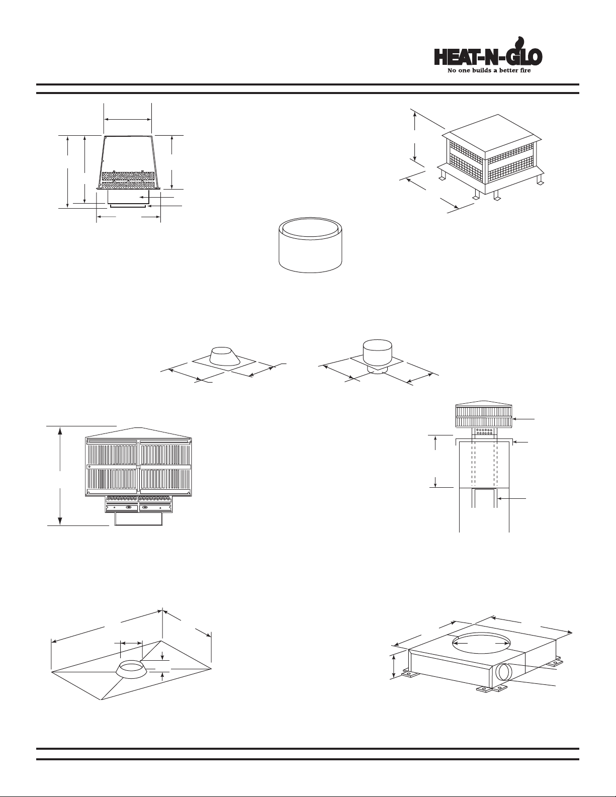
3. Termination Cap
a. Install the chimney sections up through
the chase enclosure. When using a TR344
round termination cap, the uppermost top
section of pipe must extend 6” above the
top of the chase collar to allow installation
of the storm collar and termination cap.
See Figure 20B.
b. For installations utilizing a TR342 telescop-
ing round termination cap, the uppermost
chimney section must be below the top of
the chase top, but not more than 14-1/2”
below the top of the chase top flashing
collar. See Figure 20C.
c. For installations utilizing an ST375 square
termination cap the last chimney section
must not be more than 4-1/2” below the
chase top. See Figure 20D.
d. For installation utilizing a TS345/TS345P
Square Termination Cap, the uppermost
chimney section must not be more than 3”
below the chase top. See Figure 20E.
e. Attach the chase top (CT35) to the top of
the chase.
f. Install the termination cap, following the
instructions provided with it.
NEED NEW DRAWING
Figure 20B - Installing a
TR344 Round Termination
Cap
Figure 20D - Installing an
ST375 Square Termination
Cap
Figure 20C - Installing a
TR342 Round Telescoping
Termination Cap
Figure 20E - Installing
a TS345/TS345P Square
Termination Cap
480-1081 20 4-03
Figure 20A - Chase Assembly
WARNING!
Never install a single wall slip section or smokepipe in a chase structure. The higher temperature of
this single wall pipe may radiate sufcient heat to
combustible chase materials to cause a re.
WARNING!
Detailed instructions for installation of the chase top, storm
collar and termination cap are packaged with these parts.
To avoid danger of re, all instructions must be strictly
followed, including the provision of air space clearance
between chimney system and enclosure. To protect against
the effects of corrosion on those parts exposed to the
weather, we recommend that the chase top be painted with
a rust-resistant paint.
Page 21

North Star
EPA Certied Fireplace
I. OPERATING INSTRUCTIONS
IMPORTANT! PLEASE READ BEFORE USING FIREPLACE
NOTE: Save and pass this instruction manual to subsequent home owners. The information provided is intended
to notify and warn them about making unsafe future modifications such as the addition of shelves or the use of
unauthorized parts and repairs.
1. General Information
In recent years there has been an increasing concern
about air quality. Much of the blame for poor air quality
has been placed on the burning of wood for home
heating. These replaces, like any other appliances,
must be properly operated in order to ensure that they
perform the way they are designed to perform.
Fireplaces, as well as other woodburning appliances,
have been used safely for many years. It has been our
experience that most problems are caused by improper
installation and operation of the replace. Make certain
that installation and operation of the replace system is
in accordance with these instructions.
It is reco mmended that an annual insp ection be
performed on the replace system to determine if the
ue system needs to be cleaned, or as in the case of
any appliance, if minor repairs are required to maintain
the system in top operating condition before the heating
season begins.
This factory-built replace is intended for use with solid
fuel (rewood).
2. Outside Air
A source of air (oxygen) is required in order for combustion to take place. Whatever air is consumed by the re
must be replaced through cracks around windows, under
doors, etc. Most newly constructed houses or existing
homes tted with tightly sealed doors and windows are
relatively air tight. The Nor th Star Fireplace comes
equipped with an outside air intake to feed combustion
air from outside the home, along with an outside air
termination cap. The 6” solid/ex pipe is not supplied.
Outside air is required to minimize the effects of negative
pressure within the structure. It is recommended to
utilize the shortest duct run to optimize the performance
of the Outside Air Kit. The outside air inlet thimble should
be positioned above the ground level, and must remain
clear of leaves, debris, ice and/or snow. If you live in an
area that experiences deep snow levels, this must be
taken into consideration when determining the height
placement above ground level. It must be unrestricted
while unit is in use to prevent room air starvation which
can cause smoke spillage and an inability to maintain a
re. Smoke spillage can also set off smoke alarms.
This replace will operate correctly only if adequate
WARNING!
THIS FIREPLACE HAS NOT BEEN TESTED WITH ANY
VENTED OR UNVENTED GAS LOT SET. TO REDUCE RISK
OF FIRE OR INJURY, DO NOT INSTALL A VENTED OR
UNVENTED GAS LOG SET INTO FIREPLACE.
WARNING!
ALWAYS OPERATE THIS APPLIANCE WITH THE DOOR
CLOSED AND LATCHED EXCEPT DURING START-UP AND
RE-FUELING OR WHEN USING THE FIRESCREEN.
ventilation is provided to allow proper draft to the
replace system. Hearth & Home Technologies assumes
no responsibility for the improper performance of the
replace system caused by inadequate draft due to
environmental conditions, down drafts, tight sealing
construction of the structure, or mechanical exhausting
devices which create a negative air pressure within the
structure where the replace is located.
IMPORTANT!
WARNING!
DO NOT LEAVE THE FIRE UNATTENDED WHEN THE DOOR
IS UNLATCHED OR WHEN USING THE FIRESCREEN.
UNSTABLE FIREWOOD COULD FALL OUT OF THE FIREBOX CREATING A FIRE HAZARD TO YOUR HOME.
4-03 21 480-1081
OUTSIDE AIR MUST BE IN OPEN
POSITION TO OPERATE FIREPLACE
PROPERLY.
Page 22

North Star
Slide Air Control
Left-Close Right-Open
CLOSE
OPEN
Outside Air Knob
Low
Position
Meet
Resistance
ACC Fully
Engaged
EPA Certied Fireplace
3. Burning Process
Fire requires three things to burn: fuel, air and heat. So,
if heat is robbed from the replace during the drying
stage, the new load of wood has reduced the chances
for a good clean burn. For this reason, it is always
best to burn dry, seasoned rewood. We do not advise
bur ning unseasoned wood, however if it happens,
you must open the Slide Air Control and burn the
fireplace at a high burn setting for a longer time to
start it burning.
Kindling or 1st stage:
It helps to know a little about the actual process of
burning in order to understand what goes on inside a
replace. The rst stage of burning is called the kindling
stage. In this stage, the wood is heated to a temperature
high enough to evaporate the moisture which is present
in all wood. The wood will reach the boiling point of
water (212°F) and will not get any hotter until the water
is evaporated. This process takes heat from the coals
and tends to cool the replace.
2nd stage:
The next stage of burning, the secondary stage, is the
period when the wood gives off ammable gases which
burn above the fuel with bright flames. During this
stage of burning it is very important that the ames be
maintained and not allowed to go out. This will ensure
the cleanest possible re. If you are adjusting your
replace for a low burn rate, you should close down the
air to the point where you can still maintain some ame.
If the ames tend to go out, the replace is set too low
for your burning conditions.
CAUTION:
Fireplace operation does require air. Do not take air
from other fuel burning appliances which can result in
improper venting (smoking) or air dilution. Always provide
adequate makeup air.
4. Air Control
The air enters at the upper front of the rebox, near
the top of the glass door. This preheated air supplies
the necessary fresh oxygen to mix with the unburned
gases. This air is regulated by the Slide Air Control.
For more air - slide the control to the right, for less air
- slide the control to the left.
5. Automatic Combustion Control
Typically, when you build a fire, you need to open
the controls to give the re more air so the wood will
get going. You then have to go back to the unit and
shut it down so it doesn’t overre and burn up your
wood too quickly.
With the Automatic Combustion Control system, you
can set the replace to high (all the way to the right),
start your re, and then move the Slide Air Control to
their desired burn level. The replace will automatically
go to that level after the re is fully established. This
allows for less interaction with the re by the homeowner
and more efcient use of fuel while maintaining the
desired heat output.
IMPORTANT! As you move the control rod to the
right, about three-four ths of the way you will feel
some resistance. You must move past that resistance
approximately 3/4” to fully engage the Autom atic
Combustion Control (ACC) sytstem
Final stage:
The nal stage of burning is the charcoal stage. This
occurs when the ammable gases have been mostly
burned and only charcoal remains. This is a naturally
clean por tion of the burn. The coals burn with hot
blue ames.
It is very important to reload your replace while enough
lively hot coals remain in order to provide the amount
of heat needed to dry and rekindle the next load of
wood. It is best to open the air control for a short while
before reloading. This livens up the coalbed. Open
door slowly so that ash or smoke does not exit replace
through opening. You should also break up any large
chunks and distribute the coals so that the new wood is
laid evenly on hot coals.
480-1081 22 4-03
Page 23

North Star
EPA Certied Fireplace
6. Burning Guidelines
For maximum operating efciency with the lowest
emissions, follow these operating procedures:
1. Regardless of desired heat output, when loading
the replace, burn your replace with the Slide Air
Control wide open (fully to the right) for a minimum
of 5 to 15 minutes.
2. Regulate burn rate (heat output) by using the Slide
Air Control. See page 22.
3. Heat output settings: Following 5 to 15 minutes
of burning with the control wide open (see #1
above):
BTU / Hr
Below 10,000
10,000 - 15,000
15,000 - 30,000
Maximum Heat
*These are approximate settings, and will vary with
type of wood or chimney draft.
NOTE: BURN DRY, WELL-SEASONED WOOD.
*Slide Control
Slide LEFT to Stop
Stop to 1/8” -1/2” open
1/2” - 1-1/2” open
Fully open
7. Fan Operating Instructions
Instructions with override switch in manual position.
8. Heat Zone Operating Instructions
The Heat-Zone accessory kit conveys warm air from
the replace through air duct(s) to remote locations in
the same room or other rooms of the building. One or
two Heat-Zone kits can be installed on the replace.
Follow the instructions that is supplied with the kit.
Installation of this kit MUST be performed by a qualied
service technician. If any parts are missing or damaged,
contact your local Dealer before starting installation.
DO NOT install a damaged kit.
The Heat-Zone kit is carefully engineered and must be
installed only as specied. If you modify it or any of
its components, you will void the warranty and you
may possibly cause a re hazard. Installation must be
done according to applicable local, state, provincial,
and/or national codes.
9. Operation of Fireplace with Optional Fire
Screen Instructions
CAUTION:
THE FIRESCREEN MAY BECOME EXTREMELY HOT WHILE
IN USE. ALWAYS WEAR GLOVES TO PREVENT INJURY.
1. Initial (cold) startup: Leave fan off until your replace is hot and a good coal bed is established,
approximately 30 minutes after fuel is lit.
2. High Burn Setting: The fan may be left on through-
out the burn.
3. Medium or Medium High Burn Setting: The fan
should be left off until a good burn is established,
then turned on a medium or high rate.
4. Low Burn Setting: The fan tends to cool the re-
place. Leave fan off until the burn is well established; then, if you wish, turn the fan on at a low
rate.
NOTE: The Fan is equipped with a snap disc that will
turn the blower on and off depending on the temperature of the replace. If the fan is not coming on at
the desired time, ip the override switch to manual and
operate the fan as described above.
The override switch and the fan speed control are hard
wired at time of installation and installed in a standard
wall mount with junction box on the wall.
Alway wear gloves when installing or removing the
screen as the screen may become extremely hot while
in use. Use both hands to stablize the screen. Ensure
that the screen is fully attached. Be careful not to stack
wood close to the front or too high that logs could roll out
the front. Start with a small re and adjust your heat to
desired setting. If smoke spillage occurs, put on gloves
and then remove the screen and close the doors. Refer
to Flue Draft Troubleshooting on page 4.
CAUTION:
NEVER LEAVE THE FIRE UNATTENDED WHILE USING THE
FIRESCREEN. NEVER LEAVE CHILDREN UNATTENDED
WHEN THERE IS A FIRE BURNING IN THE FIREPLACE.
CAUTION:
ALL wiring should be done by a qualied electrician and
shall be in compliance with local codes and with the
National Electric Code ANSI/NF No. 70-current (in the
United States), or with the current CSC22.1 Canadian
Electric Code (inCanada).
4-03 23 480-1081
Page 24

North Star
EPA Certied Fireplace
10. Starting A Fire
Before lighting your first fire in the fireplace, make
certain that the bafe and ceramic blanket are correctly
positioned. It should be resting against the rear
channel. Also refer to care and cleaning of gold
plated surfaces on page 28 before lighting your
rst re.
There are many ways to build a re. The basic principle
is to light easily-ignitable tinder or paper, which ignites the
fast burning kindling, which in turn ignites the slow-burning
rewood. Here is one method that works well:
1. Place several wads of crushed paper on the rebox
floor. Hea ting the flue with slightl y crumpl ed
newspaper before adding kindling keeps smoke
to a minimum.
2. Lay small dry sticks of kindling on top of the paper.
3. Fully open the Slide Air Control by moving it
completely to the right.
4. Make sure that no matches or other combustibles
are in the immediate area of the fireplace. Be
sure the room is adequately ventilated and the
ue unobstructed.
5. Light the paper in the replace. NEVER light or
rekindle replace with kerosene, gasoline, or
charcoal lighter uid; the results can be fatal.
6. Once the kindling is burning quickly, add several
full-length logs 3” or 4” in diameter. Be careful not to
smother the re. Stack the pieces of wood carefully:
near enough to keep each other hot, but far enough
away from each other to allow adequate air ow
between them.
7. When ready to reload the replace, add more logs.
Large logs burn slowly, holding a re longer. Small
logs burn fast and hot, giving quick heat.
8. Adjust the Slide Air Control; the more you close
down the Control, (sliding left) the lower and slower
the re will burn. The more you open the Air Control,
(sliding right) the more heat will be produced and
teh faster the wood will burn..
As long as there are hot coals, repeating steps 7 and 8
will maintain a continuous re throughout the season.
NOTE: The special high temperature paint that your
replace is nished with will cure as your replace heats.
You will notice an odor and perhaps see some vapor rise
from the replace surface; this is normal. We recommend
that you open a window until the odor dissipates and
paint is cured.
NOTE: Fireplace should be run full open for a minimum of
15 minutes a day to keep air passages clean.
11. Burn Rates
HIGH: Open (slide right) Slide Air Control fully. It
is important to do this when reloading the replace.
Failure to do this could result in excessive emissions
(smoke).
MEDIUM HIGH BURN RATE: After a wood load has
been burning on high for 5 to 15 minutes, close the
Slide Air Control to 1/2” - 1-1/2” distance open. (Move
the handle to left to stop and then to right for the
proper setting).
MEDIUM: After a wood load has been burning on high
for 5 to 15 minutes (longer for very large pieces or wet
wood), slide Slide Air Control left to 1/8”- 1/2” distance
open. (Move the handle to left to stop and then to right
for the proper setting).
LOW: After a wood load has been burning on high
for 5 to 15 minutes (longer for very large pieces or
wet wood), gradually slide the Air Control left to close
down the air, making sure to maintain ames in the
replace. It is very important to maintain ames in your
replace during the rst few hours of a low burn, to
avoid excessive air pollution.
12. Opacity
T
his is the measure of how cleanly your fireplace is
burning. Opacity is measured in percent; 100% opacity is
when an object is totally obscured by the smoke column
from a chimney, and 0% opacity means that no smoke
column can be seen. As you become familiar with your
replace, you should periodically check the opacity. This
will allow you to know how to burn your replace as nearly
smoke-free as possible (goal of 0% opacity).
CAUTION:
Never use gasoline, gasoline-type lantern fuel, kerosene,
charcoal lighter uid, or similar liquids to start or “freshen
up” a re in this replace. Keep all such liquids well away
from the replace.
WARNING!
Do not store fuel within the clearances to combustibles, or
in the space required for refueling and ash removal. See
maintenance instructions, “Clear Space Near the Fireplace”.
WARNING!
Burning wet, unseasoned wood can cause excessive
creosote accumulation. When ignited it can cause a
chimney re that may result in a serious house re.
480-1081 24 4-03
Page 25

North Star
EPA Certied Fireplace
13. Wood Fuel
Hardwood vs. Softwood
Your replace’s performance depends a great deal on
the quality of the rewood you use. Contrary to popular
belief, one species of wood varies very little to the
other in terms of energy content. All seasoned wood,
regardless of species, contains about 8,000 BTU’s per
pound. The important factor is that hardwoods have
a greater density than softwoods. therefore, a piece
of hardwood will contain about 60% more BTU’s than
an equal size piece of so ftwood. Since firewood
is commonly sold by the cord (128 cu. ft) a volume
measurement, a cord of seasoned oak (hardwood)
would contain about 60% more potential energy than a
cord of seasoned pine (softwood).
There are many denitions of hardwood and softwood.
Although not true in every case, one of the most reliable
is to classify them as coniferous or deciduous. Softwoods
are considered coniferous. These are trees with needlelike leaves that stay green all year and carry their seeds
exposed in a cone. Examples of softwood trees are
Douglas r, pine, spruce and cedar. Softwoods, being
more porous, require less time to dry, burn faster and
are easier to ignite than hardwoods. Deciduous trees
are broadleaf trees that lose their leaves in the fall.
Their seeds are usually found within a protective pod
or enclosure. Hardwoods fall into this category. Some
examples of deciduous trees are oak, maple, apple,
and birch. However, it should be noted that there are
some deciduous trees that are denitely not considered
hardwoods such as poplar, aspen and alder. Hardwoods
require more time to season, burn slower and are usually
harder to ignite than softwoods. Obviously, you will use
the type of wood that is most readily available in your
area. However, if at all possible the best arrangement is
to have a mix of softwood and hardwood. This way
you can use the softwood for star ting the re giving
off quick heat to bring the appliance up to operating
temperature. Then add the hardwood for slow, even heat
and longer burn time.
Fill it with a gallon of water, put it in the rebox and try
to burn it. This sounds ridiculous but that is exactly what
you are doing if you burn unseasoned wood. Dead
wood lying on the forest oor should be considered wet,
and requires full seasoning time. Standing dead wood
can be considered to be about two-thirds seasoned.
The problems with burning wet, unseasoned wood are
two fold. First, you will receive less heat output from wet
wood because it requires energy in the form of heat
to evaporate the water trapped inside. This is wasted
energy that should be used for heating your home.
Secondly, this moisture evaporates in the form of steam
which has a cooling effect in your rebox and chimney
system. When combined with tar and other organic
vapors from burning wood it will form creosote which
condenses in the relatively cool rebox and chimney.
See the maintenance section of this manual for more
information regarding creosote formation and need
for removal.
Even dry wood contains at least 15% moisture by
weight, and should be burned hot enough to keep the
chimney hot for as long as it takes to dry the wood out
- about one hour. To tell if wood is dry enough to burn,
check the ends of the logs. If there are cracks radiating
in all directions from the center, it is dry. If your wood
sizzles in the re, even though the surface is dry, it
may not be fully cured.
Seasoning
Seasoned rewood is nothing more than wood that is
cut to size, split and air dried to a moisture content of
around 20%. The time it takes to season wood varies
from around nine months for soft woods to as long as
eighteen months for hardwoods. The key to seasoning
wood is to be sure it has been split, exposing the wet
interior and increasing the surface area of each piece.
A tree that was cut down a year ago and not split is
likely to have almost as high a moisture content now
as it did when it was cut.
Moisture content
Regardless of which species of wood you burn, the
single most important factor that affects the way your
fireplace operates is the amount of moisture in the
wood. The majority of the problems replace owners
experience are caused by trying to burn wet, unseasoned
wood. Freshly cut wood can be as much water as it
is wood, having a moisture content of around 50%.
Imagine a wooden bucket that weighs about 8 pounds.
4-03 25 480-1081
Page 26

North Star
EPA Certied Fireplace
Storing Wood
Splitting wood before it is stored reduces drying time.
The following guideline will ensure properly seasoned
wood:
a. Stack the wood to allow air to circulate freely around
and through the woodpile.
b. Elevate the woodpile off the ground to allow air
circulation underneath.
c. The smaller th e pie ces, the faster the dr y ing
process. Any piece over six inches in diameter
should be split.
c. Wood should be stacked so that both ends of each
piece are exposed to air, since more drying occurs
through the cut ends than the sides. This is true
even with wood that has been split.
d. Store wood under cover, such as in a shed, or
covered with a tarp, plastic, tar paper, sheets of
scrap plywood, etc., as uncovered wood can absorb
water from rain or snow, delaying the seasoning
pr oce ss. Avoid cover ing the sides and ends
completely. Doing so may trap moisture from the
ground and impede air circulation.
14. Draft Problems
NOTE: When rst lighting your replace, it may be
necessary to pre-warm the ue to establish a draft.
This is done by holding a rolled up piece of burning
newspaper under the ue for a few moments. This
will help reduce smoke spillage during start-up.
This replace will operate correctly only if adequate
ventilation is provided to allow proper draft to the
replace system. Hearth & Home Technologies assumes
no responsibility for the improper performance of the
replace system caused by inadequate draft due to
environmental conditions, windy conditions, down drafts,
tight sealing construction of the structure, or mechanical
exhausting devices which will create a negative air
pressure within the structure where the fireplace is
located.
Flue draft is measured as negative pressure in the
chimney. The amount of negative pressure determines
how strong the draft is. The draft is important because
it draws the combustion air into the replace and pulls
the smoke out of the chimney.
There are three basic criteria essential in establishing
and maintaining ue draft:
• Availability of combustion air.
• Heat generated from the re.
• Diameter and height of the ue system.
These three factors work together as a system to create
the ue draft. Increasing or decreasing any one of them
will affect the other two and thus change the amount of
draft in the entire system.
If the re is hard to start and smoke spills out of the
replace, or you nd it difcult to establish and maintain
a moderately high burn rate, then the ue draft is too
low and corrective measures must be taken.
Be sure you have air available for combustion and that
your firewood is dry and well seasoned. Build your
res properly and according to the instructions given in
operating instructions, “Starting a Fire”. Be sure your
ue system is installed correctly and that it is the proper
diameter and height. Check for the following:
• All chimney sections are properly installed.
• The chimney is clean and free of creosote or soot
buildup.
• Make sure overhanging trees and branches are cut
back within ten feet of the top of the chimney.
• Ensure the chimney cap is clean and free of any
buildup of soot or creosote.
If you still suspect you have a low draft problem it may
be necessary to increase the volume of air in your
ue system. Since the diameter of your ue system
is matched with the size of the ue collar and should
not be changed, then the height of the system must
be increased. Add chimney sections a little at a time
until the draft improves.
In some cases, regardless of what you do, it can still
be difcult to establish the proper ue draft. This is
especially evident when using an exterior factory-built
chimney or exterior masonry chimney. Try placing
several sheets of crumpled paper on top of your kindling
as close to the ue outlet of the replace as possible.
Light this paper rst then the paper under the kindling.
The heat generated from the rapidly burning paper on
top of the kindling should help get the draft established.
Still other factors can affect how well your ue system
performs. Neighboring structures, high winds, tall trees,
even hillsides can affect air currents around the chimney.
Well designed chimney caps are available that can help.
Your replace dealer is the local expert in your area.
He can usually make suggestions or discover problems
that can be easily corrected allowing your replace to
operate correctly as it has been designed, providing
safe and economical heat for your home.
480-1081 26 4-03
Page 27

J. MAINTENANCE INSTRUCTIONS
SCREW
REMOVE (4) SCREWS
AND LIFT TOP
PAN OFF.
CAP
SLIP
SECTION
TR342, TR344
ROUND TERMINATION CAPS
ST375
SQUARE
TERMINATION CAP
LIFT UP TO
REMOVE.
SCREW
CHASE
CAP
1. REMOVE THE 4 SCREWS.
2. REMOVE SCREEN.
3. REMOVE BAFFLE.
TS345
SQUARE
TERMINATION CAP
North Star
EPA Certied Fireplace
1. Creosote and Soot
a. Formation and need for removal: When wood
is burned slowly, it produces tar and other organic
vapors which combine with expelled moisture to
form creosote. The creosote vapors condense in
the relatively cool chimney ue of a newly-started
or a slow-burning re. As a result, creosote residue
accumulates on the ue lining. When ignited, this
creosote creates an extremely hot re which may
damage the chimney or even destroy the home.
The chimney connector and chimney should be
inspected once every two months during the heating
season to determine if a creosote or soot buildup
has occurred. If creosote or soot has accumulated,
it should be removed to reduce the risk of a chimney
re.
b. Inspection: Inspect the system at the replace
connection and at the chimney top. Cooler surfaces
tend to build creosote deposits quicker, so it is
important to check the chimney from the top as well
as from the bottom.
c. Removal: The creosote or soot should be removed
with a brush specically designed for the type of
chimney in use. A chimney sweep can perform this
service. It is also recommended that before each
heating season the entire system be professionally
inspected, and cleaned and repaired if necessary.
3. Disposal of Ashes
Ashes should be placed in a metal container with a
tight-tting lid. The closed container of ashes should
be placed on a noncombustible oor or on the ground,
well away from all combustible materials, pending
nal disposal. If the ashes are disposed of by burial
in soil or otherwise locally dispersed, they should be
retained in the closed container until all embers have
thoroughly cooled.
4. Clear Space Near the Fireplace
Combustible materials must not be stored on the hearth
extension. Room furnishings such as drapes, curtains,
chairs, or other combustibles must be at least four feet
from the open front of the replace.
5. Overring:
Do not overre. Using ammable liquids or too much
wood, burning trash in the stove, or allowing too much
air into the replace, may result in overring. If the
replace glows red or even worse, white, the replace
is overred. This condition may ignite creosote in the
chimney, which can be dangerous, possibly causing a
house re. If you overre, immediately close the air
controls and door, if open, to reduce the air supply to the
re. Overring will void the replace warranty.
2. Chimney Cleaning
If you do detect a buildup of creosote, contact a qualied
chimney sweep or clean it yourself. To do this, perform
the following steps:
a. Remove the rst manifold tube and bafe. If you
do not remove the bafe, residue can pile up on
top of the bafe, and the replace will not work
properly.
b. Keep doors shut to prevent dirt and soot from
entering the room.
c. Remove the termination cap or housing top.
d. Clean with a stiff nylon brush attached to a pole OR
tie a small burlap bag lled with straw and several
small stones or sand. Work up and down the ue
until the ue is clean.
e. Replace the termination cap or housing top.
f. Reinstall bafe and manifold tube after cleaning.
4-03 27 480-1081
Figure 27A
Chimney & Termination Cap Cleaning
WARNING!
A chimney re can permanently damage your chimney
system. This damage can only be repaired by replacing the
damaged component parts. Chimney res are not covered
by the Limited Lifetime Warranty.
Page 28

North Star
EPA Certied Fireplace
6. Care and Cleaning of Glass
Your replace is equipped with ceramic super heatresistant glass, which can only be broken by impact or
misuse. Do not slam doors or impact the glass. When
closing doors, make sure that logs do not protrude
against the glass. Clean glass with a nonabrasive
glass cleaner, such as Windex. Abrasive cleaners
may scratch and cause glass to crack. Inspect glass
regularly. If you nd a crack or break, immediately
put the re out and return the door to your dealer for
replacement of glass before further use.
IMPORTANT!
REMOVE ALL LABELS FROM GLASS BEFORE
LIGHTING THE FIRST FIRE IN YOUR FIREPLACE.
IMPORTANT!
Replace with 5mm ceramic glass only
8. Glass Replacement
1. Ensure that the re is out and the appliance is
cool to the touch.
2. Protect a table or counter top with padding or
towels.
3. Remove door with broken glass from the appliance
by lifting door up and off of the hinges.
4. Lay door face down on a table or counter making
sure handle and handle attachment knob hang
over the edge of the table top so door lays at,
on a soft surface.
5. Remove the screws from each glass tab (5 on
each door) using a #2 Phillips Head screwdriver.
HINT: Soak screws in penetrating oil for easy
removal.
6. Remove the glass.
7. Use only 5mm ceramic Glass, Part GLA-480.
7. Care and Cleaning of Plated Surfaces
Clean 24 karat gold-plated surfaces with vinegar or a
glass cleaner before lighting your rst re.
CAUTION:
Do not use polishes with abrasives as it will scratch
the surface.
WARNING!
When the appliance is equipped with a 24 karat gold-plated
door, you must clean all the ngerprints and oils from the
gold surface before ring the appliance for the rst time.
Use a glass cleaner or vinegar and towel to remove the
oils. If not cleaned properly before lighting your first
re, the oils can cause permanent markings on the gold
plating. After the gold plating iis cured, the oils will not
affect the nish and little maintenance is required: just
wipe clean as needed.
8. Position the glass with edges evenly overlapping
the opening in the front door.
9. Replace the glass tabs. Be careful not to cross
thread the screws.
10. Tighten each tab just a few turns until each is
secured. Then continue to tighten each tab
alternately, a few turns at a time, until the glass
panel is tightened snugly, but not over tightened.
11. Replace the door on the appliance.
12. After the rst burn, recheck the tighness of the
screws.
480-1081 28 4-03
Page 29

9. Firebrick Replacement
3
2
3
3
3
3
3
3
3
2
1
4
1
1 1
1
4
3
3
3
3
3
3
1
1
1
1
1
3
3
4 4
2
2
The rebox of your replace is lined with high quality
rebrick, which has exceptional insulating properties.
There is no need to use a grate; simply build a re on
the rebox oor. Do not operate the replace without
rebrick.
IMPORTANT: The bricks are very similar in size. Be
certain you have the proper brick in the correct location.
Measue the brick size for accuracy.
After the coals are completely cooled, remove all old
brick and ash from unit and vacuum out rebox.
1. Remove new brick set from box and lay out to
diagram as shown in Figure 29B.
2. Lay bottom bricks in unit.
3. Install rear bricks on the top of the bottom bricks.
Slide top of bricks under clip on back of rebox
wall and push bottom of brick back.
4. Install side bricks. Slide top of brick under clips
on side of rebox and push the bottom of the brick
until it is ush with the side of the unit.
North Star
EPA Certied Fireplace
Figure 29A-Brick Pattern
Use Part SRV28111 when ordering individual brick. Provide
brick dimension or copy this page, mark the desired brick and
take it to your authroized dealer.
4-03 29 480-1081
Figure 29B-Brick Pattern
Nbr
Brick Size
1 13-1/2” x 4-1/2” x 1-1/4” 5
2 13-1/2” x 4-1/2” x 1-1/4” w/ 1-1/2” chamfer 2
3 12 x 4-1/2” x 1-1/4” 8
4 12-1/2” x 4-1/2” x 1-1/4” 2
Qty in Set
Page 30

North Star
Screwdrive
r
Slot
S
c
r
e
w
s
Rem
o
v
e
2 sc
re
w
s
a
n
d
p
ull
p
a
n
e
l
fo
rw
ar
d
(B
e
fore
fire
p
la
c
e
in
s
ta
l
la
ti
o
n)
After
fireplace
installation
Unplug wire harness before
removing fan
EPA Certied Fireplace
10. Fan Replacement
Fan Cord Location
The North Star Fireplace comes standard
equipped with two fans, installed at the
factory with electric access on the right side
of replace (as you face it).
Fan Replacement Instructions
Power must be OFF prior to servicing!
The fan assembly may be accessed before
or after the replace has been installed.
Before Fireplace Installation:
1. Remove the 2 screws located at the
outside edge of the bottom panel as
show in Figure 30A.
2. Pull panel forward and remove from
replace.
After Fireplace Installation:
1. Remove the rebrick from the bottom of
the replace.
2. Remove the 2 screws from the access
panel in the rebox oor.
3. Pry up the access panel using the
screwdrive slot and completely remove
the panel.
Removing the Fan Assembly
1. Unplug the wire harness.
2. Lift fan off of studs and remove. Repeat for
second fan if necessary. See Figure 30B.
3. Inspect the gasket and ensure it is in good
condition.
4. Replace with new fan.
5. Reinstall bottom panel or rebox access
panel in reverse order as descibed above.
Figure 30-A Accessing Fan Motor
480-1081 30 4-03
Figure 30B-Fan Motor
Page 31

North Star
Locknut
Door Cross Section
(example)
Latch Cam
Spacing Washers
Square Key
Handle
Teflon Washer
DO NOT REMOVE
EPA Certied Fireplace
11. Bafe Removal & Installation
NOTE: The bafe in the North Star Fireplace is 2700° Fiber Board. Removing hardware exposed to combustion processes
can be frustrating. If your reason for removing the bafe is simply to clean the chimney, you have alternatives which will save
time and effort. Call a qualied chimney sweep or an authorized Heat-n-Glo dealer for details.
1. Remove all ash from rebox, and extinguish all hot embers before disposal into a metal container.
2. Remove ceramic blanket from above the bafe.
3. With a 3/16” Allen wrench, remove the front manifold tube retainer bolt on the air channel under the end of the
front tube. NOTE: Soak the bolt with penetrating oil for at least 15 minutes before trying to remove it. See
Figure 31A below.
4. To remove manifold tube, slide the tube to one side until one end is out of its hole. Then, while lifting that end of
the ber board bafe, pull tube up over the air channel and out of hole at the other end. It is necessary to remove
the rst tube in order to remove the bafe.
5. Slide ber board bafe forward to front of replace and straight out through door. See Figure 31B below.
6. To install the ber board bafe, repeat steps 2 through 4 in reverse. Be sure the ber board bafe and ceramic blanket
are pushed back fully and blanket is down and at.
Figure 31A-Removing Manifold Tube
Figure 31B-Removing Bafe
shown without ceramic blanket
12. Door & Door Gasket
Periodically check the door gasket for proper seal.
As the gasket compresses or “seats” during use, it
may become necessary to adjust or tighten the door
latch.
To Adjust or Tighten Door Latch
Remove spacing washers shown in Figure 31C. At
least one spacing washer must be left in place.
OR
Replace the gasket material. Wear or damage to the
gasket material can cause air leakage into the rebox
resulting in overring and loss of efciency.
A replacement gasket, Part 834-1460 is available
from your dealer.
4-03 31 480-1081
Figure 31C-Door Handle Assembly
Page 32

1.0"
27-1/2"
27-3/8"
24"
2.0"
Ceramic Blanket
Service Parts
EXPLODED VIEW
North Star
EPA Certied Fireplace
Beginning Manufacturing Date: 02-17-03
Ending Manufacturing Date: __________
Door Assembly
Fascia Assembly
Part number list on following page.
480-1081 32 4-03
Page 33

Service Parts List
North Star
EPA Certied Fireplace
IMPORTANT: THIS IS DATED INFORMATION. The most current information is located on your dealers
VIP site. When ordering, supply serial and model numbers to ensure correct service parts.
ITEM DESCRIPTION SERIAL # PART NUMBER
Brick, Individual SRV28111
Gasketing , Glass 834-1460
Gasketing, Door (door requires 8 feet) 834-4170
Manual-Bag Assembly, (includes Owner’s Manual,
(2) Spring Handles-1/2”, (1) Spring Handle-1/4”, SRV480-1140
Paint, Fan Switches & Cover Plate, Warranty Card)
Snap Disc, F300-40 SRV480-0980
Speed Control SRV480-1250
Spring Handle, 1/4” 832-0630
Washers, 1/4” FW SAE (one under each door hinge pin) 28758
1 8” Starter Section SL1
2 Bafe, Fiberboard SRV480-0510
3 Brick, Set BRICK-480
4 Ceramic Blanket, 1”, cut to t (see drawing on page 32) 832-3400
Door Handle Assembly, (includes 2 door handles,
5
securing bracket, lock nut, latch cam key and cam latch)
6 Fan Replacement 812-4900
7 Fascia FASCIA-NS
8 Glass Assembly for Doors, 2 piece, w/gasketing GLA-480
9 Knob, Black,Outside Air 844-2640
10 Louver, Bottom, Cast, Black SRV480-7090
10 Louver, Bottom, Cast, Gold SRV480-7070
11 Louver, Top, Cast, Black SRV480-7100
11 Louver, Top, Cast, Gold SRV480-7080
12 Manifold Tube, Set of 3 TUBES-480
13 Spring Handle, 1/2” for Doors 832-0620
14 Timer SRV480-0790
15 Wiring Harness SRV480-0990
HANDLES-480
4-03 33 480-1081
Page 34

North Star
EPA Certied Fireplace
A
Accessories 6
Air Clearance 10, 17
Air Kit Knob Location 5
Ashes, Disposal of 27
Attic Insulation Shield 14
Air Controls 22-23
Automatic Combustion Control 23
B
Bafe 24, 31
Building Codes 2, 3
Burning
Guidelines 23
Process 22
Rates 24
C
Ceramic Blanket 24, 32
Chase 19
Chase Top 8, 20
Chimney
Assembling Sections Through the
Roof 16
Checking the Assembly 14
Cleaning 27
Creosote 27
Exit Point Through the Roof 16
Height Requirements 12
Inspection 2
Requirements 12
Securing the System 16
Chimney Air Kit 8
Chimney Bracket 7
Chimney Components 6-8
Chimney Requirements 10
Chimney Sections
Clearances 5
Assembling 13
Number Required 12
Chimney Stabilizer 6, 16
Clearances
Combustible Material 5
Combustion Air 2, 21
Construction 13-17
Creosote 13, 27
D
Description of the Fireplace System 3
Dimensions 5
Door & Door Gasket 31
Draft 4, 26
Index
E
Exploded Views
Door Assembly 33
E
Fascia 33
Fireplace 32
Exhaust Products 9
F
Fan Replacement 30
Fan Wiring Diagram 10
Firebrick 29
Fireplace
Enclosure 16-17
Locations 9
Firestop Spacer 7
Installation 14
Firewood 25, 26
Floor Protection 5
Flue 26
Framing 9, 10
Fuel 2, 25, 26
G
General Information 21
Glass Cleaning 28
Glass Replacement 28
Gold Plated Surfaces 28
H
Hearth Extension 17
Positioning 19
Heat Zone Kit 14, 23
I
Installation
Fireplace 13
Installation Along a Wall 9
Installation, Corner 9
Insulation Shield 7, 14
J
Joint Band 7
L
Leveling the Fireplace 13
Locations 9
M
Maintenance 27
Mantel 5, 10
Material, Sealant 19
Metal Hearth Strips 13
Mobile Home Installation 15
Moisture Content of Wood 25, 26
N
Negative Air Pressure 27
Noncombustible Material 16-18
Noncombustible SealantMaterial 18
O
Offsets/Returns 6, 11, 16
Outside Air 5, 22
Opacity 24
Overhead Obstructions 12
P
Positioning 13
Pre-Installation Preparation 9
R
Replacement Parts 33
Roof Flashing 7, 14
S
Safety 2, 13
Seasoning the Wood 25
Sidewalls/Surrounds 9
Slide Air Controls 22
Smoke 24
Soot 27
Space Requirements 9
Starting a Fire 24
T
Ten Foot Rule 12
Termination Cap 8, 20
Typical Fireplace System 3
U
UL 127 Standards 3
Uniform Building Code for Roof
Framing Details 16
V
Ventilation 4
W
Wet Insulation 2
Wiring Diagram for Fans 10
Wood
Moisture of 25
Seasoning of 25
Storing of 26
Wood Fuel 25, 26
480-1081 34 4-03
Page 35

LIMITED LIFETIME WARRANTY
The Hearth & Home Technologies limited Lifetime Warranty guarantees that the following components will work as designed
for the lifetime of the stove or Hearth & Home Technologies will repair or replace them. These items include but are not
limited to steel and cast iron components, all gas burners, gas logs, combustion chambers, heat exchanger systems,
stainless steel firebox components, plating, doors, glass damaged by thermal breakage, steel baffle supports, steel and
ceramic baffles and manifold tubes. Labor is for the first five years.
THREE YEAR WARRANTY
Our EZ Clean firepots are covered under Hearth & Home Technologies three-year warranty program. Labor is for 3 years.
TWO YEAR WARRANTY
A
ll electrical components such as but not limited to blowers, wiring, vacuum switches, speed controls, control boxes,
thermodisc switches, pilot assembly, gas valves, thermostats and remotes are covered under Hearth & Home Technologies
two-year warranty program.
ONE YEAR WARRANTY
Porcelain finishes are warranted against manufacturer defects for one year. Labor to repair or replace these parts is
covered for one year, reimbursed per our warranty service fee schedule.
CONDITIONS
This warranty is non-transferable and is made to the original retail purchaser only provided that the purchase was made
through an authorized dealer of Hearth & Home Technologies It must be installed and operated at all times in accordance
with the Installation and Operating Instructions furnished with this product, as well as any applicable local and national
codes. Any alteration, willful abuse, accident, or misuse of the product shall nullify this warranty.
Labor to repair or replace items covered under the limited Lifetime Warranty will be covered for the first five years per our
warranty service fee reimbursement schedule. Parts covered under the limited Lifetime Warranty will be covered for the
lifetime of the appliance up to a maximum of ten (10) years after Hearth & Home Technologies discontinues the model and
two (2) years for optional accessories. Adjustments, regular maintenance, cleaning and temporary repairs do not qualify for
a service call fee and will not be covered. The replacement of consumer replaceable items and installation of upgraded
component parts do not quality for a service call fee, and will not be covered.
This limited Lifetime Warranty does not extend to or include surface finish on the appliance, door gasketing, glass gasketing,
firebrick, kaowool or other ceramic insulating materials. It does not cover installation or operational-related problems such
as overfiring, use of corrosive driftwood, downdrafts or spillage caused by environmental conditions, nearby trees, buildings,
hilltops, mountains, inadequate venting or ventilation, excessive offsets, or negative air pressures caused by mechanical
systems such as furnaces, fans, clothes dryers, etc.
A
ny installation, construction, transportation, or other related costs or expenses arising from defective part(s), repair,
replacement, etc., will not be covered by this warranty, nor will Hearth & Home Technologies assume responsibility for them.
Further, Hearth & Home Technologies will not be responsible for any incidental, indirect, or consequential damages, except
as results in damage to the interior or exterior of the building in which this appliance is installed. This limited Lifetime
Warranty does not apply to the venting components, hearth components or other accessories used in conjunction with the
installation of this product not manufactured by Hearth & Home Technologies
This warranty is void if the stove has been overfired or operated in atmospheres contaminated by chlorine, fluorine, or other
damaging chemicals, the stove is subjected to prolonged periods of dampness or condensation, or there is any damage to
the stove or other components due to water or weather damage which is the result of, but not limited to, improper chimney
or venting installation. Hearth & Home Technologies may, at its discretion, fully discharge all obligations with respect to this
warranty by either repairing or replacing the unit, or refunding the wholesale price of the defective part(s).
This limited Lifetime Warranty is effective on all appliances sold after May 1, 2002 and supersedes any and all warranties
currently in existence.
Policy 250-8620 Rev C
Lifetime Warranty
4-03 35 480-1081
Page 36

ATTENTION INSTALLER:
PLEASE RETURN
THESE INSTRUCTIONS
TO THE HOME OWNER
WHEN INSTALLATION
IS COMPLETE.
4-03 36 480-1081
 Loading...