

Page 1
Models:
Aztec
Bravo
Owner’s Manual
Installation and Operation
CAUTION
DO NOT DISCARD THIS MANUAL
Important operating
•
and maintenance
instructions included.
Read, understand and follow
•
these instructions for safe
installation and operation.
WARNING
If the information in these instruc-
tions is not followed exactly, a fi re
or explosion may result causing property
damage, personal injury, or death.
• Do not store or use gasoline or other fl am-
mable vapors and liquids in the vicinity of
this or any other appliance.
• What to do if you smell gas
- Do not try to light any appliance
- Do not touch any electrical switch. Do not
use any phone in your building.
- Immediately call your gas supplier from a
neighbor’s phone. Follow the gas supplier’s instructions.
- If you cannot reach your gas supplier, call
the fi re department.
• Installation and service must be performed
by a qualifi ed installer, service agency , or the
gas supplier.
This appliance may be installed as an OEM installation in manufactured home (USA only) or mobile home and must be installed
in accordance with the manufacturer’s instructions and the manufactured home construction and safety standard, Title 24 CFR,
Part 3280 or Standard for Installation in Mobile Homes, CAN/
CSA Z240MH.
This appliance is only for use with the type(s) of gas indicated
on the rating plate.
Leave this manual with
•
party responsible for
use and operation.
DO NOT
DISCARD
WARNING
HOT! DO NOT TOUCH.
SEVERE BURNS MAY RESULT.
CLOTHING IGNITION MAY RESULT.
Glass and other surfaces are hot during
operation and cool down.
• CAREFULLY SUPERVISE children in same room as
appliance.
• Alert children and adults to hazards of high temperatures.
• Do NOT operate with protective barriers open or
removed.
• Keep clothing, furniture, draperies and other
combustibles away.
This appliance has been supplied with an integral barrier
to prevent direct contact with the fi xed glass panel. Do
NOT operate the appliance with the barrier removed.
Contact your dealer or Hearth & Home Technologies if the
barrier is not present or help is needed to properly install one.
In the Commonwealth of Massachusetts:
• installation must be performed by a licensed plumber
or gas fi tter;
• a CO detector shall be installed in the room where the
appliance is installed.
• Keep children away.
Installation and service of this appliance should be
performed by qualifi ed personnel. Hearth & Home
Technologies suggests NFI certifi ed or factory-trained
professionals, or technicians supervised by an NFI certifi ed professional.
Hearth & Home Technologies, Inc. • Bravo, Aztec • InD • 703-900 Rev. N • 8/06 1
Page 2
Read this manual before installing or operating this appliance.
Please retain this owner’s manual for future reference.
Congratulations
Congratulations on selecting a Hearth & Home
Technologies gas appliance —an elegant and clean
alternative to wood burning appliances. The Hearth &
Home Technologies gas appliance you have selected is
designed to provide the utmost in safety, reliability, and
effi ciency.
As the owner of a new appliance, you’ll want to read and
carefully follow all of the instructions contained in this
Owner’s Manual. Pay special attention to all Cautions
and Warnings.
Homeowner Reference Information
Model Name: ___________________________________________ Date purchased/installed: __________________
Serial Number: __________________________________________ Location on appliance: ____________________
Dealership purchased from: _______________________________ Dealer Phone: __________________________
Notes: _______________________________________________________________________________________
_____________________________________________________________________________________________
This Owner’s Manual should be retained for future
reference. We suggest that you keep it with your other
important documents and product manuals.
The information contained in this Owner’s Manual, unless
noted otherwise, applies to all models and gas control
systems.
Your new Hearth & Home Technologies gas appliance will
give you years of durable use and trouble-free enjoyment.
Welcome to the Hearth & Home Technologies family of
appliance products!
We recommend that you record the following
pertinent information about your appliance.
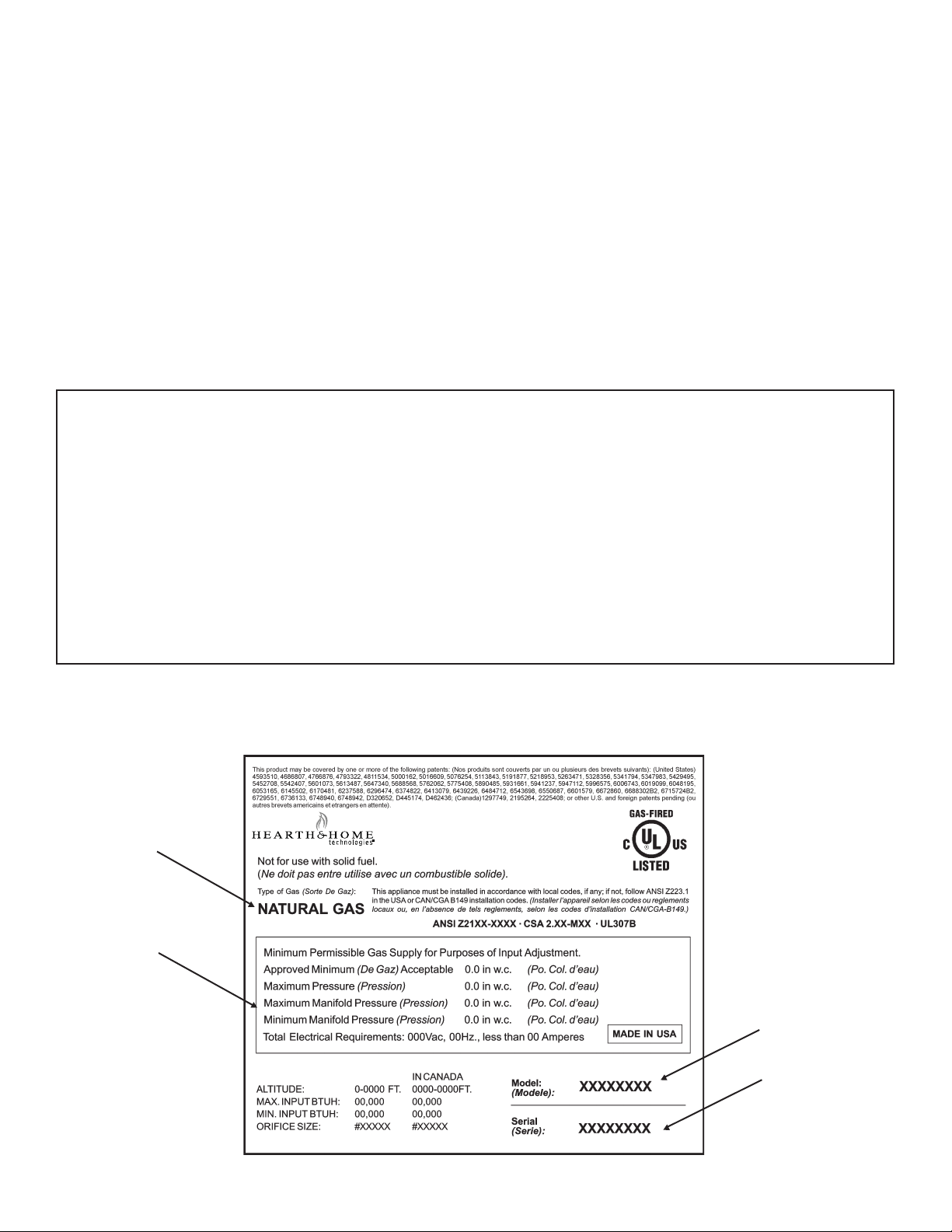
Listing Label Information/Location
Type of Gas
Gas and Electric
Information
The model information regarding your specifi c appliance can be found on
the rating plate usually located in the control area of the appliance.
Hearth & Home Technologies, Inc.
20802 Kensington Blvd. Lakeville, Mn 55044
Model Number
Serial Number
2
Hearth & Home Technologies • Bravo, Aztec • InD • 703-900 Rev. N • 8/06
Page 3

- Table of Contents -
Section 1: Listing and Code Approvals
A. Appliance Certifi cation ................................... 4
B. Glass Specifi cations ......................................4
C. BTU Specifi cations ........................................4
D. High Altitude Installations .............................. 4
E. Non-Combustible Materials Specifi cations ....4
F. Combustible Materials Specifi cations ............4
Section 2: Getting Started
A. Design and Installation Considerations .........5
B. Tools and Supplies Needed ........................... 5
C. Inspect Appliance and Components .............. 5
Section 3: Framing and Clearances
A. Selecting Appliance Location......................... 6
B. Constructing the Appliance Chase ................7
C. Clearances .................................................... 7
Î
D. Mantel Projections ......................................... 8
Section 4: Termination Locations
A. Vent Termination Minimum Clearances ......... 9
Section 5: Vent Information and Diagrams
A. Vent Table Key ..............................................11
B. Use of Elbows...............................................11
C. Measuring Standards ...................................11
Î
Section 6: Vent Clearances and Framing
A. Pipe Clearances to Combustibles ...............17
C. Vertical Penetration Framing ....................... 18
Section 7: Appliance Preparation
A. Securing and Leveling the Appliance .......... 19
Section 8: Installing Vent Pipe
A. Assembly of Vent Sections .......................... 20
B. Disassembly of Vent Sections ..................... 22
C. Installing Heat Shield & Termination Cap ...23
D. Installing Roof Flashing and Vertical
Termination Cap ..........................................24
D. Vent Diagrams ............................................. 12
B. Wall Penetration Framing ............................ 17
Section 9: Gas Information
A. Fuel Conversions ...................................... 26
B. Gas Pressures .......................................... 26
C. Gas Connection ........................................ 26
Section 10: Electrical Information
A. Recommendation for Wire ........................ 28
B. Connecting to the Appliance .....................28
C. Intellifi re Ignition System Wiring ................ 28
D. Wall Switch (Required) ............................. 28
E. Junction Box ............................................. 30
F. Wall Switch Installation for Fan ................. 30
Section 11: Finishing
A. Mantel Projections .................................... 31
B. Facing Material ......................................... 31
C. Finishing Styles .........................................32
Section 12: Appliance Setup
A. Remove Shipping Materials ......................35
B. Clean the Appliance .................................. 35
C. Accessories .............................................. 35
D. Lava Rock, Ember Placement .................. 35
E. Positioning the Logs ................................. 36
F. Glass Assembly ........................................42
G. Air Shutter Setting ..................................... 42
Section 13: Operating Instructions
A. Before Lighting Appliance .........................43
B. Lighting Appliance .....................................44
C. After Appliance is Lit ................................. 45
D. Frequently Asked Questions ..................... 45
Section 14: Troubleshooting
A. Intellifi re Ignition System ........................... 46
Section 15: Maintaining and Servicing Appliance. .......... 48
Section 16: Reference Materials
A. Appliance Dimension Diagram ................. 50
B. Vent Components Diagrams ..................... 51
C. Service Parts ............................................ 54
D. Bravo Warranty ......................................... 59
Aztec Warranty ......................................... 60
E. Contact Information ..................................61
Í
Í
Í
Í
Í
Í
Î = Contains updated information.
Hearth & Home Technologies, Inc. • Bravo, Aztec • InD • 703-900 Rev. N • 8/06 3
Page 4
1
Listing and Code Approvals
A. Appliance Certifi cation
MODELS: Aztec, Bravo
LABORATORY: Underwriters Laboratories, Inc. (UL)
TYPE: Direct Vent Gas Appliance Heater
STANDARD: ANSI Z21.88-2000•CSA2.33-M2000•UL307B
This product is listed to ANSI standards for “Vented Gas
Appliance Heaters” and applicable sections of “Gas Burning Heating Appliances for Manufactured Homes and
Recreational Vehicles”, and “Gas Fired Appliances for Use
at High Altitudes”.
NOT INTENDED FOR USE AS A PRIMARY HEAT SOURCE.
This appliance is tested and approved as either supplemental
room heat or as a decorative appliance. It should not be factored as primary heat in residential heating calculations.
These models may be installed in a bedroom or bed-sitting
room in the USA and Canada.
B. Glass Specifi cations
Hearth & Home T echnologies appliances manufactured with
tempered glass may be installed in hazardous locations
such as bathtub enclosures as defi ned by the Consumer
Product Safety Commission (CPSC). The tempered glass
has been tested and certifi ed to the requirements of ANSI
Z97.1 and CPSC 16 CFR 1202 (Safety Glazing Certifi cation
Council SGCC# 1595 and 1597. Architectural T esting, Inc.
Reports 02-31919.01 and 02-31917.01).
This statement is in compliance with CPSC 16 CFR
Section 1201.5 “Certifi cation and labeling requirements”
which refers to 15 U.S. Code (USC) 2063 stating “…Such
certifi cate shall accompany the product or shall otherwise
be furnished to any distributor or retailer to whom the
product is delivered.”
Some local building codes require the use of tempered
glass with permanent marking in such locations. Glass
meeting this requirement is available from the factory.
Please contact your dealer or distributor to order.
NOTE: This installation must conform with local codes. In the
absence of local codes you must comply with the National
Fuel Gas Code, ANSI Z223.1-latest edition in the U.S.A.
and the CAN/CGA B149 Installation Codes in Canada.
C. BTU Specifi cations
Models
(U.S. or Canada)
Aztec, Bravo (NG)
Aztec, Bravo (LP)
US
(0-2000 FT)
CANADA
(2000-4500 FT)
US
(0-2000 FT)
CANADA
(2000-4500 FT)
Maximum
Input BTUH
23,000 42
20,700 43
23,000 53
20,700 54
Orifi ce
Size
(DMS)
D. High Altitude Installations
U.L. Listed gas appliances are tested and approved without
requiring changes for elevations from 0 to 2000 feet in the
U.S.A. and Canada.
When installing this appliance at an elevation above 2000
feet, it may be necessary to decrease the input rating by
changing the existing burner orifi ce to a smaller size. Input
rate should be reduced by 4% for each 1000 feet above
a 2000 foot elevation in the U.S.A., or 10% for elevations
between 2000 and 4500 feet in Canada. If the heating
value of the gas has been reduced, these rules do not
apply. To identify the proper orifi ce size, check with the
local gas utility.
If installing this appliance at an elevation above 4500 feet
(in Canada), check with local authorities.
WARNING
Do NOT use this appliance if any part has been under water.
Immediately call a qualifi ed service technician to inspect
the appliance and to replace any part of the control system
and any gas control which has been under water.
E. Non-Combustible Materials Specifi cation
Material which will not ignite and burn. Such materials are
those consisting entirely of steel, iron, brick, tile, concrete,
slate, glass or plasters, or any combination thereof.
Materials that are reported as passing ASTM E 136,
Standard Test Method for Behavior of Materials in a
Vertical Tube Furnace at 750oC, shall be considered
non-combustible materials.
F. Combustible Materials Specifi cation
Materials made of or surfaced with wood, compressed
paper, plant fi bers, plastics, or other material that can
ignite and burn, whether fl ame proofed or not, or whether
plastered or unplastered shall be considered combustible
materials.
4
Hearth & Home Technologies • Bravo, Aztec • InD • 703-900 Rev. N • 8/06
Page 5
2
Getting Started
A. Design and Installation Considerations
Hearth & Home Technologies direct vent gas appliances
are designed to operate with all combustion air siphoned
from outside of the building and all exhaust gases expelled to the outside. No additional outside air source is
required.
CAUTION
Check building codes prior to installation.
• Installation MUST comply with local, regional, state
and national codes and regulations.
• Consult local building, fi re offi cials or authorities
having jurisdiction about restrictions, installation
inspection, and permits.
When planning an appliance installation, it’s necessary to
determine the following information before installing:
• Where the appliance is to be installed.
• The vent system confi guration to be used.
• Gas supply piping.
• Electrical wiring.
• Framing and fi nishing details.
• Whether optional accessories—devices such as a fan,
wall switch, or remote control—are desired.
C. Inspect Appliance and Components
WARNING
Inspect appliance and components for
damage. Damaged parts may impair safe
operation.
• Do NOT install damaged components.
• Do NOT install incomplete components.
• Do NOT install substitute components.
Report damaged parts to dealer.
• Carefully remove the appliance and components from
the packaging.
• The vent system components and trim doors are shipped
in separate packages.
• The gas logs may be packaged separately and must
be fi eld installed.
• Report to your dealer any parts damaged in shipment,
particularly the condition of the glass.
• Read all of the instructions before starting the installation. Follow these instructions carefully during the installation to ensure maximum safety and
benefi t.
WARNING
Keep appliance dry.
• Mold or rust may cause odors.
• Water may damage controls.
B. Tools and Supplies Needed
Before beginning the installation be sure that the following
tools and building supplies are available.
Reciprocating saw Framing material
Pliers Hi temp caulking material
Hammer Gloves
Phillips screwdriver Framing square
Flat blade screwdriver Electric drill and bits (1/4 in.)
Plumb line Safety glasses
Level 1/2 - 3/4 inch length, #6 or #8 Self-drilling screws
Manometer Voltmeter
Tape measure Noncorrosive leak check solution
One 1/4 inch female connection (for optional fan).
• Modifi cation of the appliance or vent system.
• Installation other than as instructed by Hearth & Home
Technologies.
• Improper positioning of the gas logs or the glass door.
• Installation and/or use of any component part not
approved by Hearth & Home Technologies.
Any such action may cause a fi re hazard.
WARNING
Hearth & Home Technologies disclaims any
responsibility for, and the warranty will be
voided by, the following actions:
• Installation and use of any damaged
appliance or vent system component.
Hearth & Home Technologies, Inc. • Bravo, Aztec • InD • 703-900 Rev. N • 8/06 5
Page 6
3
Framing and Clearances
NOTE:
• Illustrations refl ect typical installations and are FOR
DESIGN PURPOSES ONLY.
• Illustrations/diagrams are not drawn to scale.
• Actual installation may vary due to individual design
preference.
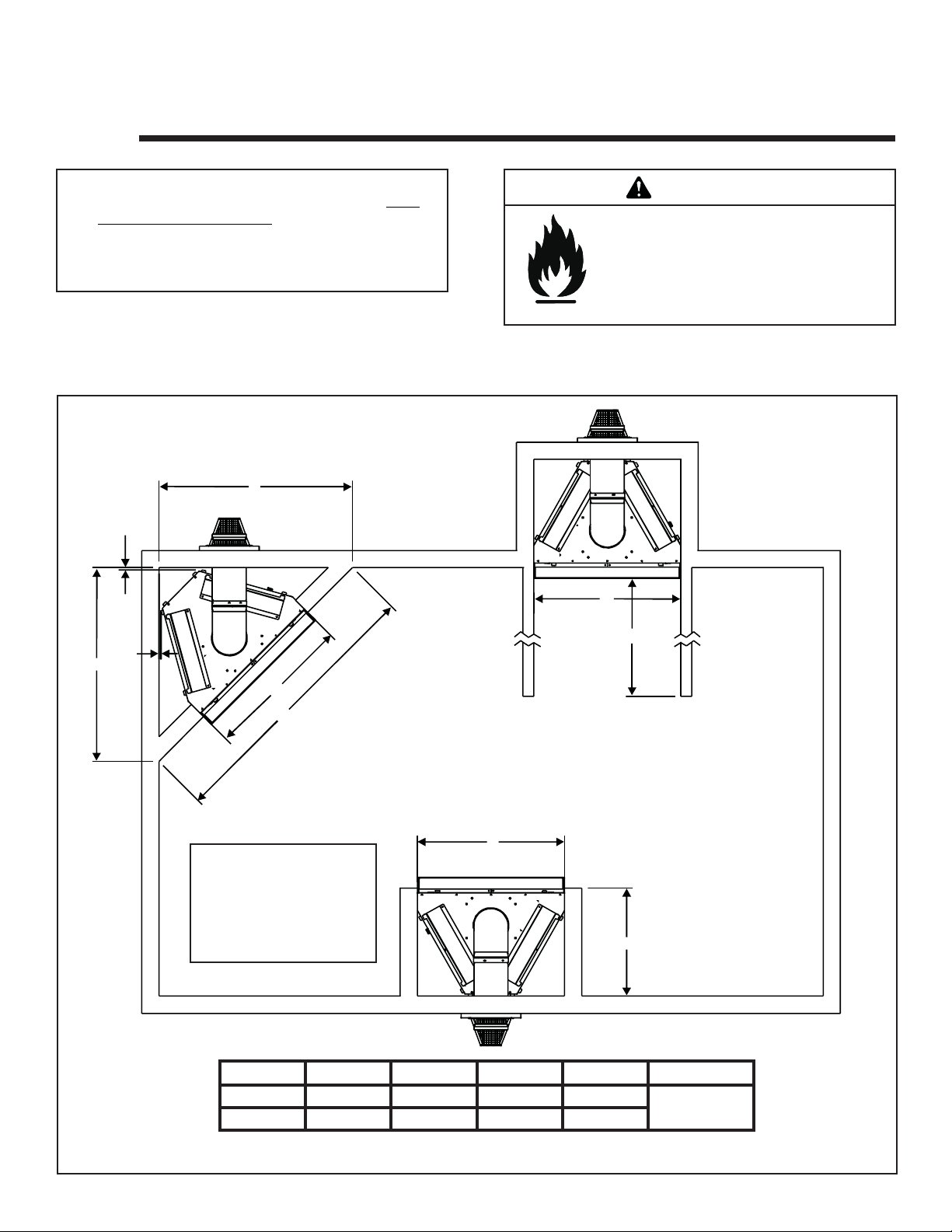
A. Selecting Appliance Location
When selecting a location for your appliance it is important to
consider the required clearances to walls (see Figure 3.1).
A
½
WARNING
Fire Risk
Provide adequate clearance:
• Around air openings
• To combustibles
• For service access
Locate appliance away from traffi c areas.
NOTE: For actual appliance dimensions refer to Section 16.
B
E
½
A
B
C
In addition to these framing dimensions, also reference the following sections:
• Clearances and Mantel Projections (Section 3.C and 3.D)
• Vent Clearances and Framing (Section 6).
B
NOTE:These dimensions
are for fl ush wall fi nishing
method. For a recessed
arch fi nishing method refer
to Option B in Finishing
(Section 11).
ABCD E
Inches 45-1/8 34-3/8 63-7/8 25-1/4
Millimeters 1146 873 1622 641
D
No maximum
Figure 3.1 Appliance Locations
6
Hearth & Home Technologies • Bravo, Aztec • InD • 703-900 Rev. N • 8/06
Page 7
B. Constructing the Appliance Chase
A chase is a vertical boxlike structure built to enclose the
gas appliance and/or its vent system. Vertical vents that run
on the outside of a building may be, but are not required to
be, installed inside a chase.
Construction of the chase may vary with the type of building.
These instructions are not substitutes for the requirements
of local building codes. Local building codes MUST be
checked.
Chases should be constructed in the manner of all outside
walls of the home to prevent cold air drafting problems.
The chase should not break the outside building envelope
in any manner.
Walls, ceiling, base plate and cantilever fl oor of the chase
should be insulated. V apor and air infi ltration barriers should
be installed in the chase as per regional codes for the rest of
the home. Additionally, in regions where cold air infi ltration
may be an issue, the inside surfaces may be sheetrocked
and taped for maximum air tightness.
T o further prevent drafts, the wall shield and ceiling fi restops
should be caulked with high temperature caulk to seal gaps.
Gas line holes and other openings should be caulked with
high temp caulk or stuffed with unfaced insulation. If the
appliance is being installed on a cement slab, a layer of
plywood may be placed underneath to prevent conducting
cold up into the room.
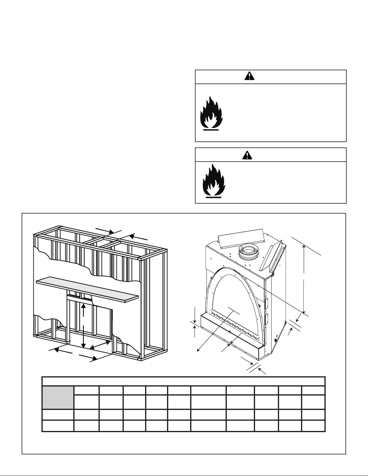
C. Clearances
WARNING
Fire Risk.
Odor Risk.
• Install appliance on hard metal or wood
surfaces extending full width and depth of
appliance.
• Do NOT install appliance directly on
carpeting, vinyl, tile or any combustible
material other than wood.
WARNING
Fire Risk.
• Construct chase to all clearance
specifi cations in manual.
• Locate and install appliance to all
clearance specifi cations in manual
A
FROM
TOP OF
FINISHING
STRIP TO
E
CEILING
F
B
C
*
D
J
G
I
H
Clearance to Combustibles
A B C* D E F G H IJ
Rough
Opening
(Vent Pipe)
Inches 10 44 25-1/4 35-3/8 34-7/8 0 0 1/2 1/2 36
Rough
Opening
(Height)
Rough
Opening
(Depth)
Rough
Opening
(Width)
Clearance
to Ceiling
Non-Combustible
Floor
Combustible
Flooring
Behind
Appliance
Sides of
Appliance
Front of
Appliance
Millimeters 25 1118 641 699 886 0 0 13 13 914
*For additional framing options and dimensions, see Section 11, Finishing.
Figure 3.2 Clearances to Combustibles
Hearth & Home Technologies, Inc. • Bravo, Aztec • InD • 703-900 Rev. N • 8/06 7
Page 8
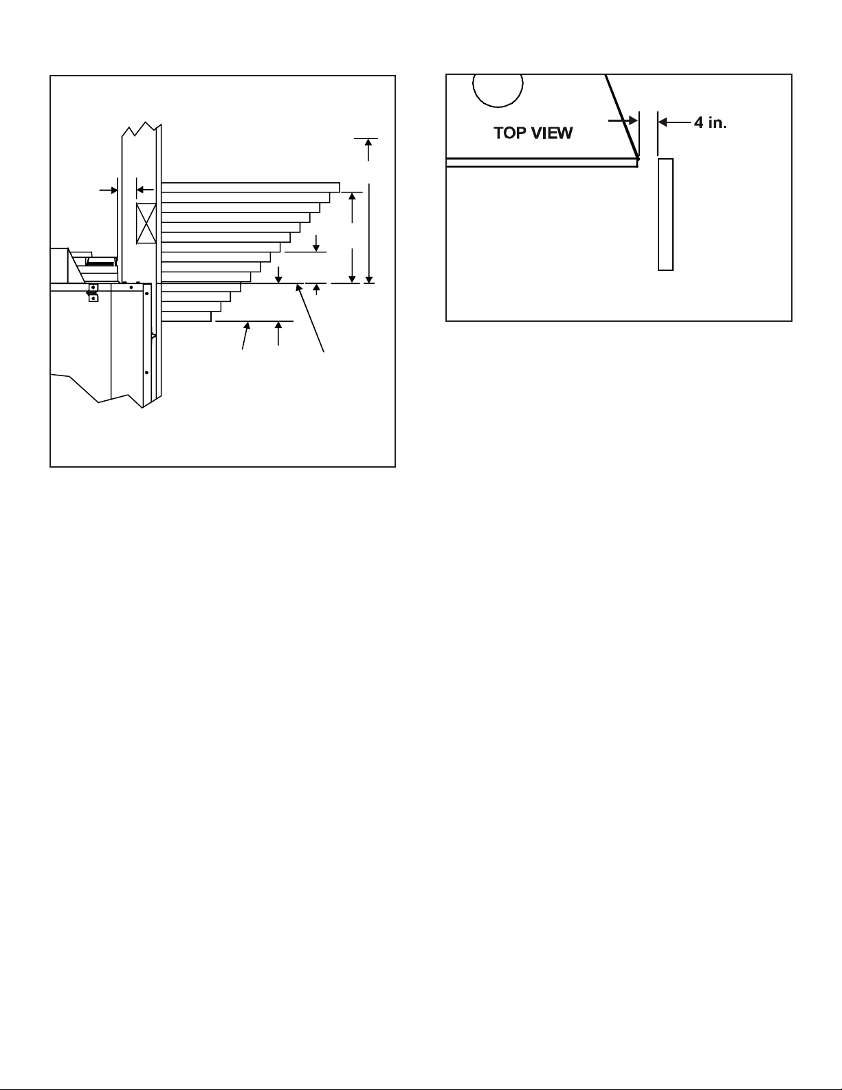
D. Mantel Projections
Note: All
measurements
in inches.
1 INCH
MINIMUM
TO
VENT PIPE
14
13
12
11
10
9
8
7
6
5
FINISHING STRIP
37/8
TOP OF
Figure 3.3 Clearances to Mantels or other
Combustibles above Appliance
15
16
31/8
18
17
TOP OF
UNIT
CEILING
91/8
MIN.
31
Figure 3.4 Clearances to Mantel Legs or Wall Projections
(Acceptable on both sides of opening.)
8
Hearth & Home Technologies • Bravo, Aztec • InD • 703-900 Rev. N • 8/06
Page 9
4
Termination Locations
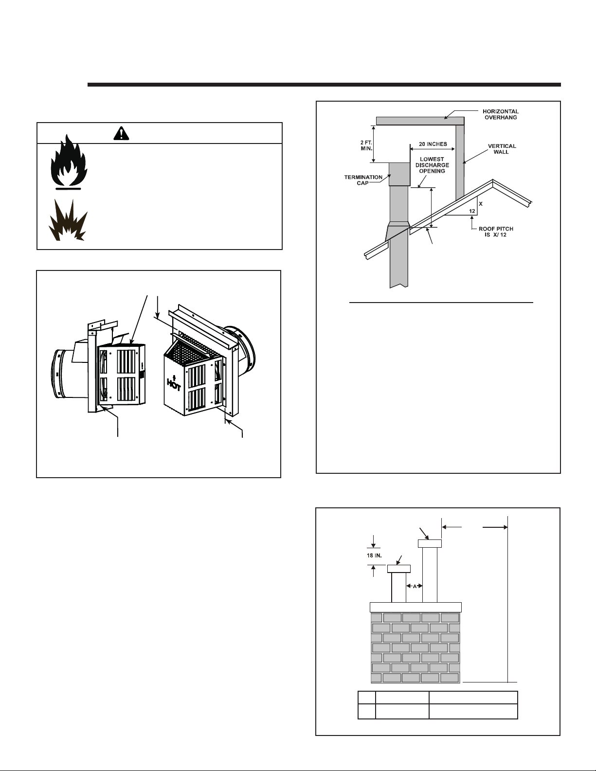
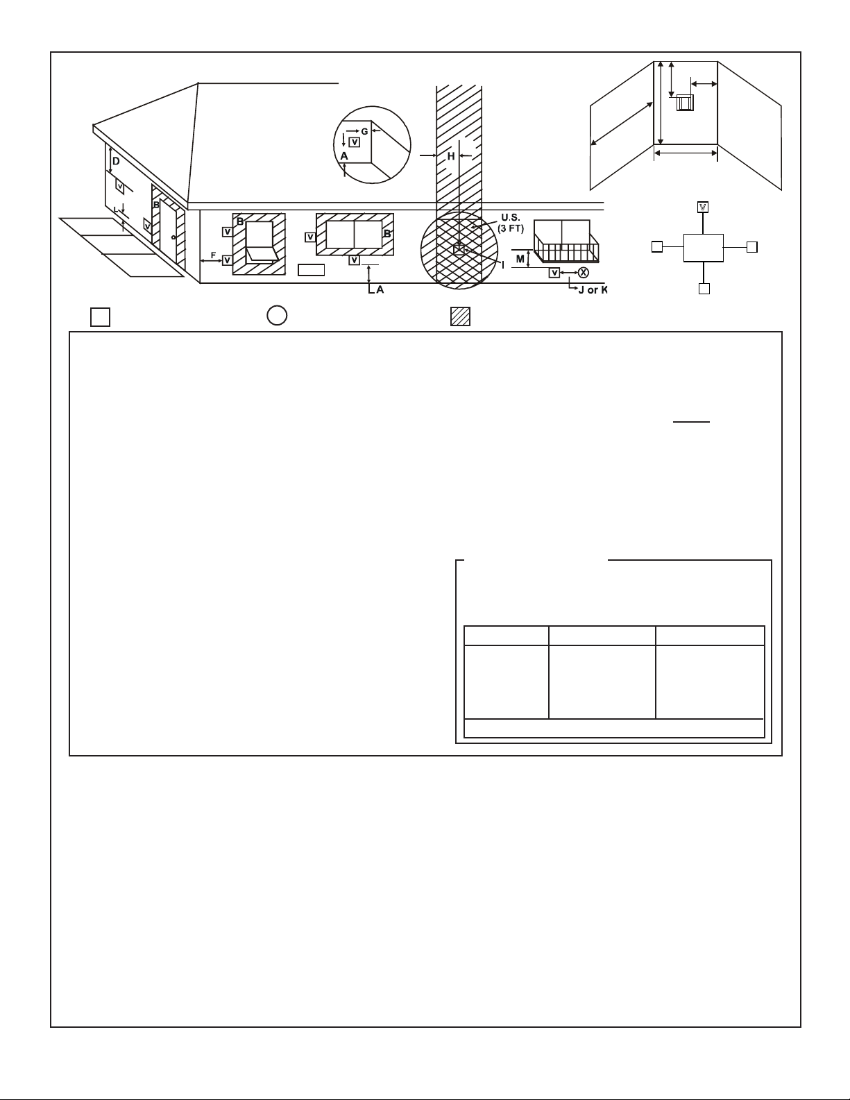
A. Vent Termination Minimum Clearances
WARNING
Fire Risk.
Explosion Risk.
Maintain vent clearance to combustibles as
specifi ed.
• Do not pack air space with insulation or
other materials.
Failure to keep insulation or other materials
away from vent pipe may cause fi re.
Measure vertical clearances from this surface.
Measure horizontal clearances from this surface.
(See Figure 4.4 for specifi c clearances)
Figure 4.1
H (MIN.) - MINIMUM HEIGHT FROM ROOF
TO LOWEST DISCHARGE OPENING
Roof Pitch H (Min.) Ft.
Flat to 6/12...........................................................1.0*
Over 6/12 to 7/12 .................................................1.25*
Over 7/12 to 8/12 .................................................1.5*
Over 8/12 to 9/12 .................................................2.0*
Over 9/12 to 10/12 ...............................................2.5
Over 10/12 to 11/12 .............................................3.25
Over 11/12 to 12/12 .............................................4.0
Over 12/12 to 14/12 .............................................5.0
Over 14/12 to 16/12 .............................................6.0
Over 16/12 to 18/12 .............................................7.0
Over 18/12 to 20/12 .............................................7.5
Over 20/12 to 21/12 .............................................8.0
* 3 foot minimum in snow regions
Figure 4.2 Minimum Height from Roof to
Lowest Discharge Opening
Figure 4.2 specifi es minimum vent heights for various
pitched roofs.
GAS, WOOD OR FUEL
OIL TERMINATION
GAS
TERMINATION
Gas Termination Wood & Fuel Oil Termination
A
Figure 4.3 Multiple Vertical Termination
Hearth & Home Technologies, Inc. • Bravo, Aztec • InD • 703-900 Rev. N • 8/06 9
6 in. 20 in.
20 IN.
(MINIMUM) TO
PERPENDICULAR
WALL
(GAS ONLY)
Page 10
R
(See Note 2)
M
N
P
Q
V
T
Electrical
Service
D*
V
S
V
S
V
= VENT TERMINAL
V
A = 12 inches ...............clearances above grade, veranda,
(See Note 1)
X
= AIR SUPPLY INLET
porch, deck or balcony
B = 12 inches ...............clearances to window or door
that may be opened, or to permanently closed window. (Glass)
D* = 18 inches ...............vertical clearance to unventilated
soffi t or to ventilated soffi t located
above the terminal
*30 inches ..............for vinyl clad soffi ts and below
electrical service
F = 9 inches ................clearance to outside corner
G = 6 inches .................clearance to inside corner
H = 3 ft. (Canada) ........not to be installed above a gas
meter/regulator assembly within 3
feet (90cm) horizontally from the
center-line of the regulator
I = 3 ft. (U.S.A.)
6 ft. (Canada) .........clearance to gas service regulator
vent outlet
J = 9 inches (U.S.A.)
12 inches (Canada) clearance to non-mechanical
air supply inlet to building or the
combustion air inlet to any other
appliance
= AREA WHERE TERMINAL IS NOT PERMITTED
K = 3 ft. (U.S.A.)
6 ft. (Canada) ...........clearance to a mechanical
(powered) air supply inlet
L** = 7 ft. ..........................clearance above paved
(See Note 1)
sidewalk or a paved driveway
located on public property
M*** = 18 inches.................clearance under veranda, porch,
deck, balcony or overhang
42 inches ................vinyl
S = 6 inches ...................clearance from sides of elec-
(See Note 5)
trical service
T = 12 inches ..................clearance above electrical
(See Note 5)
service
Alcove Applications
N = 6 inches ..................non-vinyl sidewalls
12 inches ................vinyl sidewalls
P = 8 ft.
Q
MIN
1 cap 3 feet 2 x Q
2 caps 6 feet 1 x Q
3 caps 9 feet 2/3 x Q
4 caps 12 feet 1/2 x Q
Q
= # termination caps x 3 R
MIN
= (2 / # termination caps) x Q
MAX
R
MAX
ACTUAL
ACTUAL
ACTUAL
ACTUAL
ACTUAL
** a vent shall not terminate directly above a sidewalk or paved driveway
which is located between two single family dwellings and serves both
dwellings.
*** only permitted if veranda, porch, deck or balcony is fully open on a
minimum of 2 sides beneath the fl oor, or meets Note 2.
NOTE 1: On private property where termination is less than 7 feet above
a sidewalk, driveway, deck, porch, veranda or balcony, use of a listed cap
shield is suggested. (See vents components page)
NOTE 2: Termination in an alcove space (spaces open only on one side
and with an overhang) are permitted with the dimensions specifi ed for
vinyl or non-vinyl siding and soffi ts. 1. There must be 3 feet minimum
between termination caps. 2. All mechanical air intakes within 10 feet
of a termination cap must be a minimum of 3 feet below the termination
cap. 3. All gravity air intakes within 3 feet of a termination cap must be a
minimum of 1 foot below the termination cap.
Figure 4.4 Minimum Clearances for Termination
NOTE 3: Local codes or regulations may require different
clearances.
NOTE 4: Termination caps may be hot. Consider their proximity to
doors or other traffi c areas.
NOTE 5: Location of the vent termination must not interfere with
access to the electrical service.
WARNING: In the U.S: V ent system termination is NOT permitted in
screened porches. Y ou must follow side wall, overhang and ground
clearances as stated in the instructions.
In Canada: Vent system termination is NOT permitted in screened
porches. Vent system termination is permitted in porch areas with
two or more sides open. You must follow all side walls, overhang
and ground clearances as stated in the instructions.
Hearth & Home Technologies assumes no responsibility for the
improper performance of the appliance when the venting system
does not meet these requirements.
CAUTION: IF EXTERIOR WALLS ARE FINISHED WITH VINYL SIDING, IT IS SUGGESTED THAT A VINYL PROTECTOR KIT BE INSTALLED.
10
Hearth & Home Technologies • Bravo, Aztec • InD • 703-900 Rev. N • 8/06
Page 11
Vent Information and Diagrams
V
5
A. Vent Table Key
The abbreviations listed in this vent table key are used in
the vent diagrams.
Symbol Description
V
V
H
H
First section (closest to appliance of vertical length
1
Second section of vertical length
2
First section (closest to appliance) of horizontal length
1
Second section of horizontal length
2
WARNING
Fire Hazard.
Explosion Risk.
Asphyxiation Risk.
Do NOT connect this gas appliance to a
chimney fl ue serving a separate solid-fuel or
gas burning appliance.
• Vent this appliance directly outside.
• Use separate vent system for this appliance.
May impair safe operation of this appliance or
other appliances connected to the fl ue.
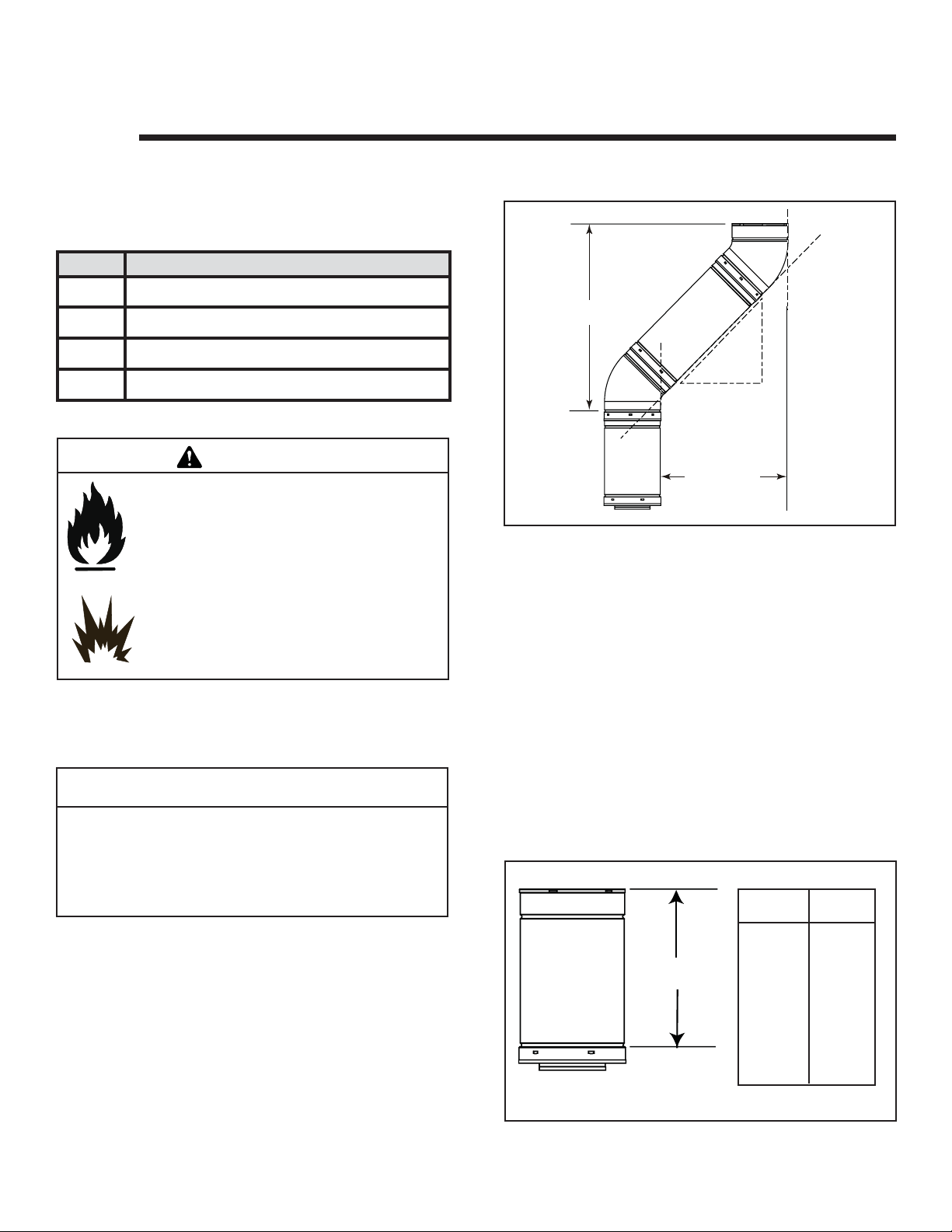
B. Use of Elbows
ertical
12 in.
8-1/2 in.
Horizontal
Figure 5.1
8-1/2 in.
C. Measuring Standards
Vertical and horizontal measurements listed in the vent
diagrams were made using the following standards.
1. Pipe measurements are shown using the effective length
of pipe (see Figure 5.2).
2. Measurements are made from the appliance outer wrap,
not from the standoffs.
3. Horizontal terminations are measured to the outside
mounting surface (fl ange of termination cap) (see Figure
4.1).
CAUTION
ALL vent confi guration specifi cations MUST be followed.
• This product is tested and listed to these
specifi cations.
• Appliance performance will suffer if specifi cations are
not followed.
Diagonal runs have both vertical and horizontal vent aspects when calculating the effects. Use the rise for the
vertical aspect and the run for the horizontal aspect (see
Figure 5.1).
Two 450 elbows may be used in place of one 900 elbow. On
450 runs, one foot of diagonal is equal to 8.5 inches horizontal run and 8.5 inches vertical run. A length of straight
pipe is allowed between two 450 elbows (see Figure 5.1).
Hearth & Home Technologies, Inc. • Bravo, Aztec • InD • 703-900 Rev. N • 8/06 11
4. Vertical terminations are measured to bottom of termination cap.
5. Horizontal pipe installed level with no rise.
Length/
Inches
Effective
Height/Length
Figure 5.2 DVP Pipe Effective Length
Pipe
DVP4 4
DVP6 6
DVP12 12
DVP24 24
DVP36 36
DVP48 48
DVP6A 3 to 6
DVP12A 3 to 12
DVP12MI 3 to 12
DVP24MI 3 to 24
Page 12
D. Vent Diagrams
Fire Risk. Explosion Risk.
Do NOT pack insulation or other combustibles between ceiling fi restops.
• ALWAYS maintain specifi ed clearances around venting and fi restop systems.
• Install wall shield and ceiling fi restops as specifi ed.
Failure to keep insulation or other material away from vent pipe may cause fi re.
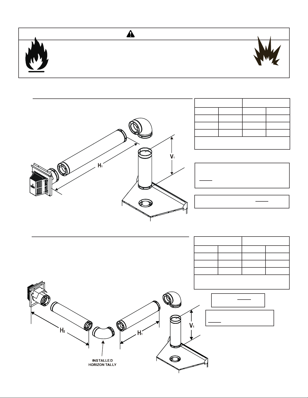
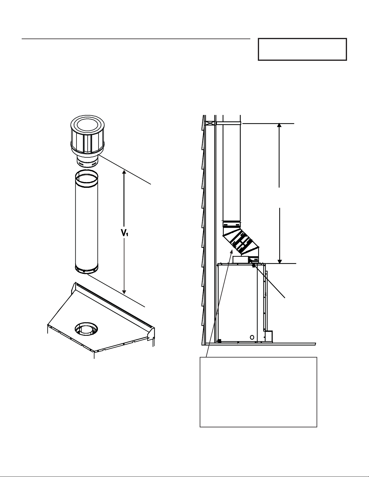
1. Top Vent - Horizontal Termination
WARNING
One Elbow
Figure 5.3
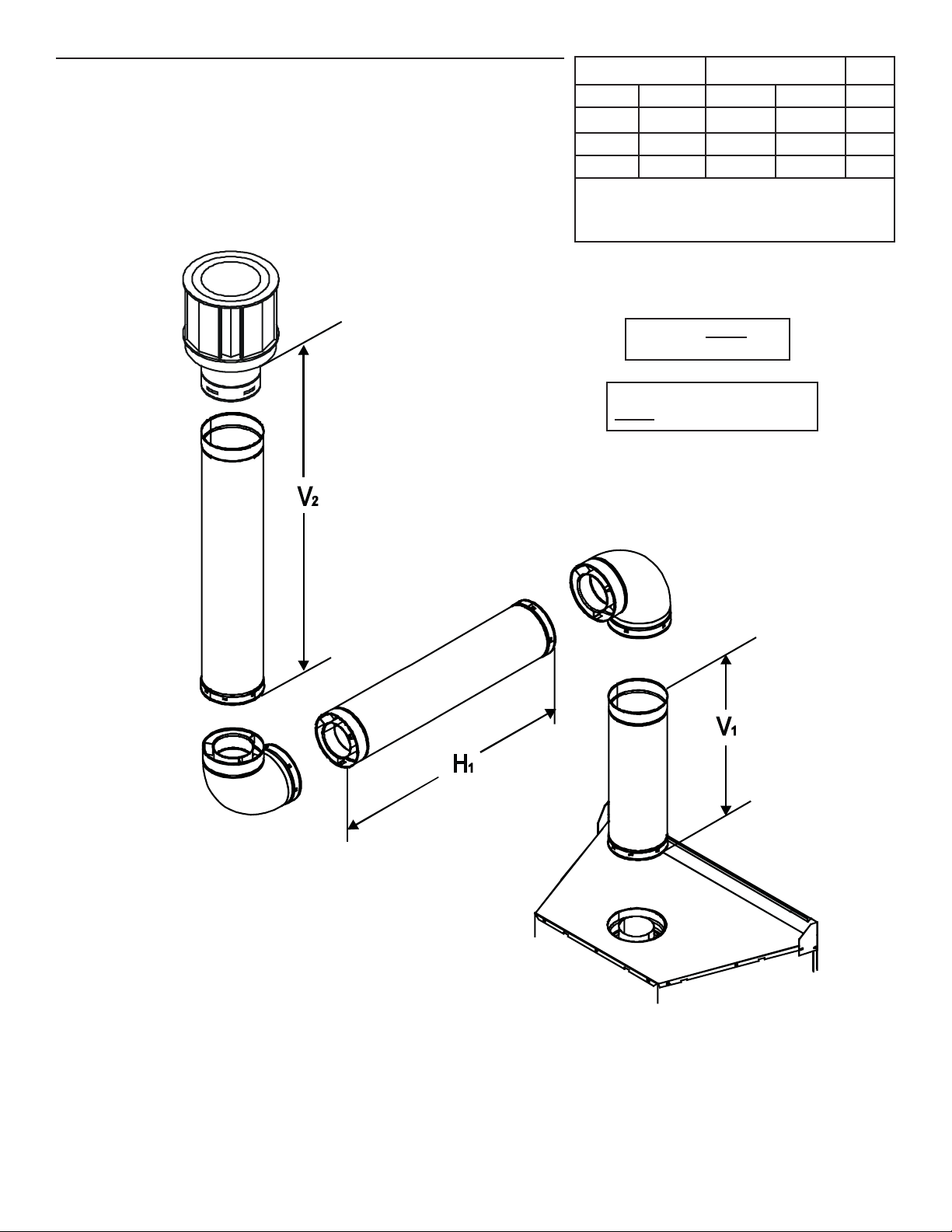
Two Elbows
V1 Minimum H1 Maximum
3 ft. 0.9 m 2 ft. 0.6 m
4 ft. 1.2 m 4 ft. 1.2 m
5 ft. 1.5 m 6 ft. 1.8 m
12 ft. 3.7m 20 ft. 6.1 m
+ H1 = 40 ft. (12.2 m) Maximum
V
1
H1 = 20 ft. (6.1 m) Maximum
NOTE: When venting with one elbow, a
straight section of venting (3 ft. minimum)
MUST be attached directly to starting collars on unit.
NOTE: The fi rst elbow used MUST always
be DVP90ST.
V1 Minimum H1 + H2 Maximum
3 ft. 0.9 m 2 ft. 0.6 m
4 ft. 1.2 m 4 ft. 1.2 m
5 ft. 1.5 m 6 ft. 1.8 m
12 ft. 3.7 m 20 ft. 6.1 m
V1 + H1 + H2 = 40 ft. (12.2 m) Maximum
H1 + H2 = 20 ft. (6.1 m) Maximum
Í
Í
12
Figure 5.4
NOTE:
minimum of 3 feet.
NOTE: The first elbow used
MUST always be DVP90ST.
Hearth & Home Technologies • Bravo, Aztec • InD • 703-900 Rev. N • 8/06
V
MUST be a
1
Page 13
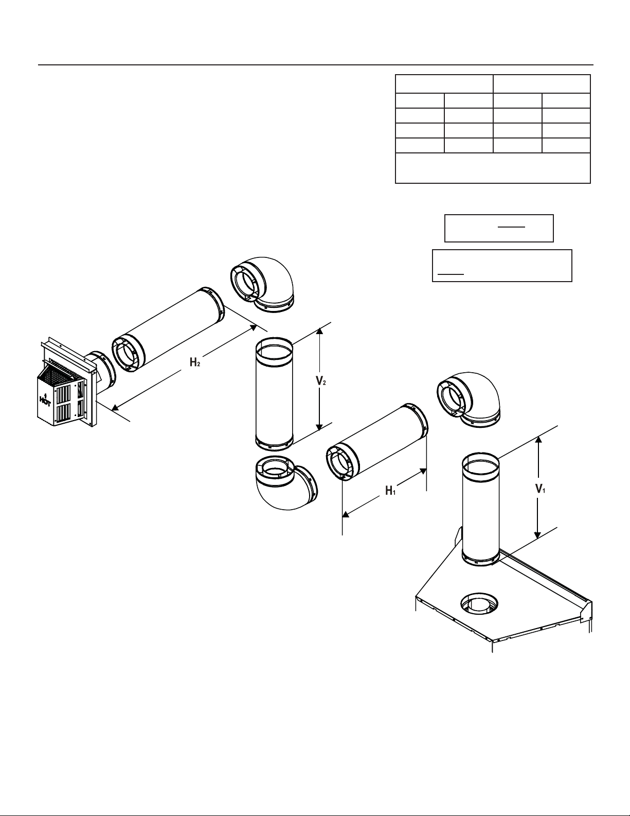
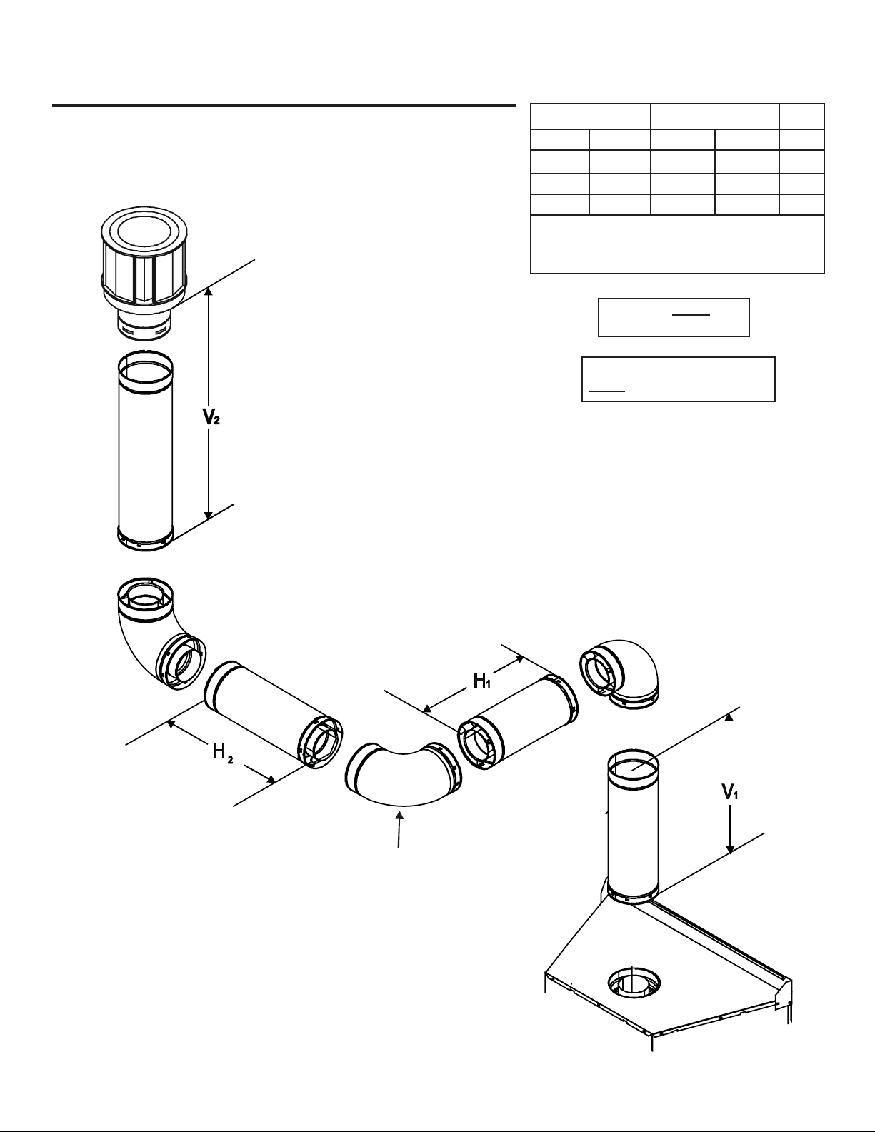
1. Top Vent - Horizontal Termination - (continued)
Three Elbows
V1 + V
V1 + V2 + H1 + H2 = 40 ft. (12.2 m) Maximum
Minimum H1 + H2 Maximum
2
3 ft. 0.9 m 2 ft. 0.6 m
4 ft. 1.2 m 4 ft. 1.2 m
5 ft. 1.5 m 6 ft. 1.8 m
12 ft. 3.7 m 20 ft. 6.1 m
H1 + H2 = 20 ft. (6.1 m) Maximum
NOTE: V1 MUST be a
minimum of 3 feet.
NOTE: The first elbow used
MUST always be DVP90ST.
Í
Figure 5.5
Hearth & Home Technologies, Inc. • Bravo, Aztec • InD • 703-900 Rev. N • 8/06 13
Page 14
2. Top Vent - Vertical Termination
No Elbow
V1 = 46 ft. Max. (14.0 m)
8 FT.
(2.4mm)
Figure 5.6
14
FLUE
OUTLET
Note: A 45O elbow may be attached
directly to starting collars on unit only
if used in conjunction with a return 45O
elbow AND terminating vertical with V =
8 feet MINIMUM.
A straight section of pipe can be used
between the two 450 elbows.
Hearth & Home Technologies • Bravo, Aztec • InD • 703-900 Rev. N • 8/06
Page 15
Two Elbows
V1 Minimum H1 Maximum V
3 ft. 0.9 m 2 ft. 0.6 m *
4 ft. 1.2 m 4 ft. 1.2 m *
5 ft. 1.5 m 6 ft. 1.8 m *
12 ft. 3.7 m 20 ft. 6.1 m *
V
+ V2 + H1 = 40 ft (12.2 m) Maximum
1
*No specifi c restrictions on this value EXCEPT
V1 + V2 + H
NOTE: V1 MUST be a
minimum of 3 feet.
NOTE: The first elbow used
MUST always be DVP90ST.
cannot exceed 40 ft (12.2 m)
1
Í
2
Figure 5.7
Hearth & Home Technologies, Inc. • Bravo, Aztec • InD • 703-900 Rev. N • 8/06 15
Page 16
2. Top Vent - Vertical Termination - (continued)
Three Elbows
V1 H
+ H
1
2
3 ft. 0.9 m 2 ft. 0.6 m *
4 ft. 1.2 m 4 ft. 1.2 m *
5 ft. 1.5 m 6 ft. 1.8 m *
12 ft 3.7 m 20 ft. 6.1 m *
+ H2 = 20 ft (6.1 m) Maximum
H
*No specifi c restrictions on this value EXCEPT
1
V1 + V2 + H1 + H
= 40 ft (12.2 m) Maximum
2
NOTE: V1 MUST be a
minimum of 3 feet.
NOTE: The first elbow used
MUST always be DVP90ST.
V
2
Figure 5.8
16
INSTALLED
HORIZONTALLY
Hearth & Home Technologies • Bravo, Aztec • InD • 703-900 Rev. N • 8/06
Page 17
6
A
Vent Clearances and Framing
A. Pipe Clearances to Combustibles
WARNING
Fire Risk.
Explosion Risk.
Maintain vent clearance to combustibles as
specifi ed.
• Do not pack air space with insulation or
other materials.
Failure to keep insulation or other materials
away from vent pipe may cause fi re.
NOTE: Slope
not required.
1 in. CLEARANCE
ROUND VERTICAL
SECTIONS
3 in. TOP
CLEARANCE
1 in. SIDE AND
BOTTOM CLEARANCE
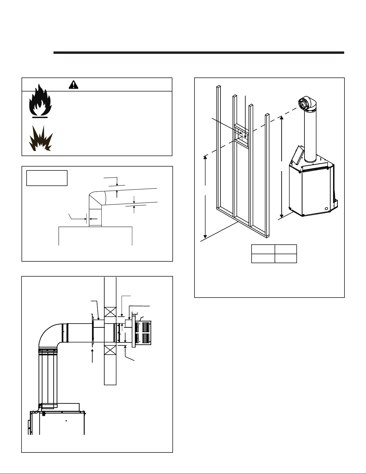
B. Wall Penetration Framing
10 in.
12 in.
B
A
Figure 6.1 Pipe Clearances
HEAT
SHIELD
SHIELD
FIRES TOP
WALL
WALL
3in.TOP
CLEAR ANCE
HEAT
SHIELD
1in.CLEARANCE
BOTTOM & SIDES
A* B
77 in. 76 in.
* Shows center of vent framing hole for top venting. The
center of the hole is one (1) inch (25.4mm) above the
center of the horizontal vent pipe.
Figure 6.2 Exterior Wall Hole
Combustible Wall Penetration
Frame a hole in a combustible wall for an interior wall
shield fi restop, (Figure 6.2) whenever a wall is penetrated.
Use same size framing materials as those used in the wall
construction. The wall shield fi restop maintains minimum
clearances and prevents cold air infi ltration.
Non-Combustible Wall Penetration
If the hole being penetrated is surrounded by noncombustible materials such as concrete, a hole with diameter one
inch greater than the pipe is acceptable.
Figure 6.2 Horizontal Venting Clearances to
Î
Combustible Materials
Hearth & Home Technologies, Inc. • Bravo, Aztec • InD • 703-900 Rev. N • 8/06 17
Page 18
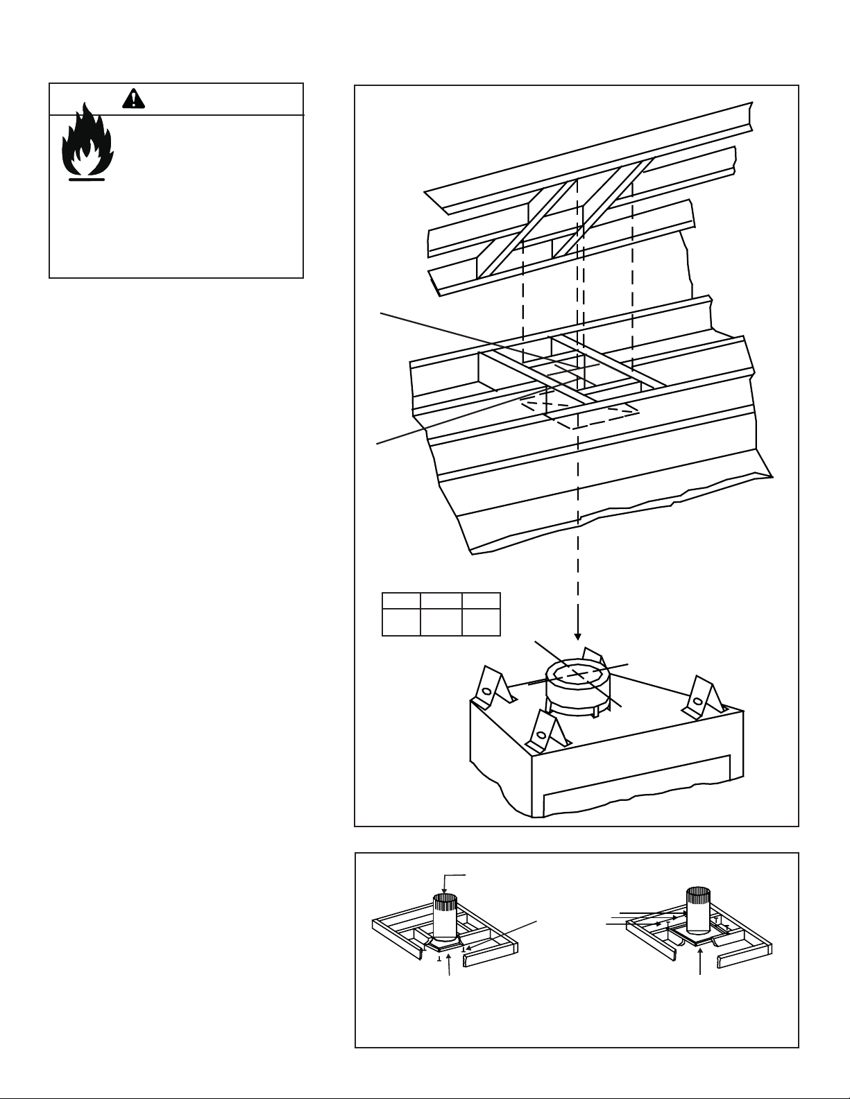
C. Vertical Penetration Framing
WARNING
Fire Hazard
Keep loose materials or blown
insulation from touching the
vent pipe.
• National building codes recommend us-
ing attic shield to keep loose materials/
blown insulation from contacting vent.
• Hearth & Home Technologies requires
the use of an attic shield.
ATTIC
ABOVE
Installing the Ceiling Firestop
• Frame an opening 10 inches by 10
inches whenever the vent system
penetrates a ceiling/fl oor (see Figure
6.3).
• Frame the area with the same sized
lumber as used in ceiling/fl oor joist.
• When installing a top vent vertical termination appliance the hole should be
directly above the appliance, unless the
fl ue is offset.
• Do not pack insulation around the vent.
Insulation must be kept away from the
pipe.
A
B
A B
DVP
10 in. 10 in.
PIPE
Installing Attic Shield
Note: An additional ceiling fi restop is not
required if attic shield is used.
• Frame opening for attic shield.
• Attic shield may be installed above or
below ceiling (see Figure 6.4).
• Secure with three fasteners on each
side.
• Fold tabs at top of attic shield in toward
vent pipe. Tabs must keep vent pipe
centered within shield.
• Field construct additional shield height if
insulation is deeper than height of attic
shield.
18
Hearth & Home Technologies • Bravo, Aztec • InD • 703-900 Rev. N • 8/06
Figure 6.3
BEND TABS IN
AROUND PIPE
3 FASTENERS
PER SIDE
ATTIC SHIELD INSTALLED
BELOW CEILING
Figure 6.4 Installing the Attic Shield
ATTIC SHIELD INS TALLED
ABOVE CEILING
Page 19
Appliance Preparation
7
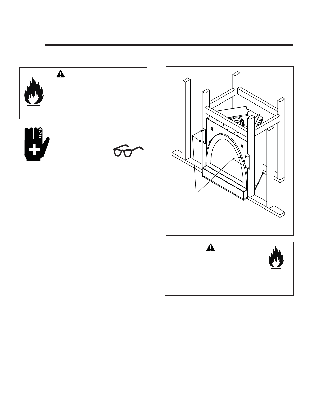
A. Securing and Leveling the Appliance
WARNING
Fire Risk.
• Prevent contact with sagging, loose
insulation.
• Do NOT install against combustible
materials such as exposed insulation,
plastic and insulation backer.
CAUTION
Sharp Edges
• Wear protective gloves
and safety glasses during installation.
The diagram shows how to properly position, level, and
secure the appliance (see Figure 7.1). Nailing tabs are provided to secure the appliance to the framing members.
• Place the appliance into position.
• Level the appliance from side to side and front to
back.
• Shim the appliance as necessary. It is acceptable to use
wood shims.
• Bend out nailing tabs on each side.
• Keep nailing tabs fl ush with the framing.
• Secure the appliance to the framing by using nails or
screws through the nailing tabs. Holes are provided in the
basepan (inside the hearth) for securing to the fl oor.
NAILINGTABS
(BOTH SIDES)
Figure 7.1 Proper Positioning, Leveling and
Securing of a Appliance
WARNING
Fire Risk.
• ALWAYS maintain specifi ed
clearances around the appliance.
• Do NOT notch into the framing around the appliance spacers.
Failure to keep insulation, framing or other material away
from the appliance may cause fi re.
Hearth & Home Technologies, Inc. • Bravo, Aztec • InD • 703-900 Rev. N • 8/06 19
Page 20

Installing Vent Pipe
8
A. Assembly of Vent Sections
WARNING
Fire Risk
Exhaust Fumes Risk
Impaired Performance of Appliance
• Overlap pipe slip sections at least 1-1/2 inches.
• Use pilot holes for screws.
• Screws must not exceed one inch long.
• Pipe may separate if not properly joined.
Attaching Vent to the Firebox Assembly
To attach the fi rst pipe section to the collars, slide the male end of
the inner vent of the pipe section over the inner collar on the fi rebox
assembly . At the same time, slide the outer fl ue over the outer collar
on the appliance. Push the pipe section into the appliance collar until
all the lances (see Figure 8.1) have snapped in place. Tug slightly
on the section to confi rm it has completely locked into place.
Assembling Pipe Sections
Insert the inner fl ue of section A into the fl ared inner fl ue of
section B.
Start the outer fl ue of section A over the outer fl ue of section B (see
Figure 8.2). Note: The end of the pipe sections with the lances/tabs
on it will face towards the appliance.
Once both inner and outer fl ues
are started, press section A onto
section B fi rmly until all lances
have snapped into place. Check
to make sure they have snapped
together (see Figure 8.3) and
the seams are not aligned (see
Figure 8.4). Tug slightly on section A to confi rm it has completely
locked into place. It is acceptable
to use screws no longer than 1
inch to hold outer pipe sections
together. If predrilling holes, do
NOT penetrate inner pipe.
Note: Make sure that the seams are not aligned to prevent unintentional disconnection.
CORRECT
Figure 8.4 Seams
Figure 8.1 Lances
A
B
Figure 8.2
Figure 8.3
INCORRECT
For 90° and 45° elbows that are changing the vent direction from
horizontal to vertical, one screw minimum should be put in the outer
fl ue at the horizontal elbow joint to prevent the elbow from rotating.
Use screws no longer than 1 inch. If predrilling screw holes, do
NOT penetrate inner pipe.
20
Hearth & Home Technologies • Bravo, Aztec • InD • 703-900 Rev. N • 8/06
Page 21

Assembling Minimum Installations (MI) Sections
MI sections are non-unitized so that they can be cut to a
certain length. Cut these sections to length from the nonexpanded end (see Figure 8.5).
They can then be attached by fi rst connecting the expanded
end of the MI inner fl ue with the inner pipe from the adjacent
pipe section and securing with three screws. The expanded
portion of the MI inner fl ue must overlap completely with
the unexpanded end of the adjacent pipe section.
The outer fl ue can then be inserted into the adjacent outer
fl ue expanded end and attached to the next pipe section
with three screws. The other end of the MI pipe section can
then be attached by fi tting another pipe section to it and
snapping it together, as normal.
Assembling DVP-12A Slip Sections
The outer fl ue of the slip section should slide over the outer
fl ue of the pipe section and into (inner fl ue) the last pipe
section (see Figure 8.6) .
Figure 8.5
Slide together to the desired length, making sure that a
1-1/2 inch outer fl ue overlap is maintained between the
pipe section and slip section.
The pipe and slip section need to be secured by driving
two screws through the overlapping portions of the outer
fl ues using the pilot holes (see Figure 8.7).
This will secure the slip section to the desired length and
prevent it from separating. The slip section can then be
attached to the next pipe section.
If the slip section is too long, the inner and outer fl ues of
the slip section can be cut to the desired length.
Figure 8.6 Slip Section Pilot Holes
Figure 8.7 Screws into Slip Section
Hearth & Home Technologies, Inc. • Bravo, Aztec • InD • 703-900 Rev. N • 8/06 21
Page 22

Securing the Vent Sections
Vertical Sections
Vertical sections of pipe must be supported every 8 feet
after the 25 foot maximum unsupported rise. The vent support or plumber’s strap (spaced 120° apart) may be used
to do this (see Figure 8.8).
Horizontal Sections
Horizontal sections of vent must be supported every 5 feet
with a vent support or plumber’s strap.
Figure 8.8 Securing Vertical Pipe Sections
B. Disassembly of Vent Sections
T o disassemble any two pieces of pipe, rotate either section
(see Figure 8.10), so that the seams on both pipe sections
are aligned (see Figure 8.11). They can then be carefully
pulled apart.
WARNING
Fire Risk.
Explosion Risk.
Combustion Fume Risk.
Use vent run supports per installation
instructions.
Connect vent sections per installation
instructions.
• Maintain all clearances to combustibles.
• Do NOT allow vent to sag below
connection point to appliance.
Improper support may allow vent to sag or separate.
Figure 8.9 Securing Horizontal Pipe Sections
Figure 8.10 Rotate Seams for Disassembly
22
Figure 8.11 Align and Disassemble Vent Sections
Hearth & Home Technologies • Bravo, Aztec • InD • 703-900 Rev. N • 8/06
Page 23

C. Installing Heat Shield and Horizontal Termination Cap
WARNING
Fire Hazard
Impaired performance of appliance
• Telescoping fl ue section of termination
cap MUST be used when connecting pipe
section to termination cap.
• Maintain a 1-1/2 inch minimum overlap on
telescoping fl ue section of termination cap.
WARNING
Fire Risk
Exhaust Fumes Risk
Impaired Performance of Appliance
• Overlap pipe slip sections at least 1-1/2 inches.
• Use pilot holes for screws.
• Screws must not exceed 1 inch long.
• Pipe may separate if not properly joined.
Heat Shield Requirements for Horizontal Termination
Installing the Horizontal Termination Cap
Vent termination must not be recessed in the wall. Siding
may be brought to the edge of the cap base.
Flash and seal as appropriate for siding material at outside
edges of cap.
When installing a horizontal termination cap, follow the cap
location guidelines as prescribed by current ANSI Z223.1
and CAN/CGA-B149 installation codes.
WARNING
Burn Risk
• Local codes may require installation of a
cap shield to prevent anything or anyone
from touching the hot cap.
For all horizontally vented appliances, a heat shield MUST
be placed one inch above the top of the vent between the
wall shield fi restop and the base of the termination cap.
There are two sections of the heat shield. One section attaches to the wall shield fi restop with two screws. The remaining
section is attached to the cap in the same manner.
If the wall thickness does not allow the required 1-1/2
inch heat shield overlap, an extended heat shield must
be used.
The extended heat shield will need to be cut to the thickness of the wall and be attached to the wall shield fi restop.
The small leg on the extended heat shield should rest on
the top of the vent (pipe section) to properly space it from
the pipe section (see Figure 8.12).
Figure 8.12 Venting through the Wall
NOTE: Where required, an exterior wall fl ashing is
available.
When penetrating a brick wall, a brick extension kit
is available for framing the brick.
Hearth & Home Technologies, Inc. • Bravo, Aztec • InD • 703-900 Rev. N • 8/06 23
Page 24

D. Installing Roof Flashing and
Vertical Termination Cap
To install roof fl ashing see Figure 8.13.
For installation of vertical termination cap see minimum vent
heights for various pitched roofs (see Figure 8.13) .
To attach the vertical termination cap, slide the inner collar of the cap into the inner fl ue of the pipe section and
place the outer collar of the cap over the outer fl ue of the
pipe section.
Secure with three screws into the outer fl ue. Secure the cap
by driving the three self-tapping screws (supplied) through
the pilot holes in the outer collar of the cap into the outer
fl ue of the pipe (see Figure 8.14).
TERMINATION CAP
H (MIN.) - MINIMUM HEIGHT FROM ROOF
TO LOWEST DISCHARGE OPENING
Roof Pitch H (Min.) Ft.
Flat to 6/12.......................................1.0*
Over 6/12 to 7/12 ...........................1.25*
Over 7/12 to 8/12 .............................1.5*
Over 8/12 to 9/12 .............................2.0*
Over 9/12 to 10/12 ............................ 2.5
Over 10/12 to 11/12 ........................ 3.25
Over 11/12 to 12/12 .......................... 4.0
Over 12/12 to 14/12 .......................... 5.0
Over 14/12 to 16/12 .......................... 6.0
Over 16/12 to 18/12 .......................... 7.0
Over 18/12 to 20/12 .......................... 7.5
Over 20/12 to 21/12 .......................... 8.0
* 3 foot minimum in snow regions
Figure 8.13 Minimum Height from Roof to
Lowest Discharge Opening
(1 of 3)
CAULK
Figure 8.14
STORM
COLLAR
SCREWS
24
WARNING
Fire Risk.
Explosion Risk.
Inspect external vent cap regularly.
• Ensure no debris blocks cap.
• Combustible materials blocking cap may
ignite.
• Restricted air fl ow affects burner operation.
Hearth & Home Technologies • Bravo, Aztec • InD • 703-900 Rev. N • 8/06
Page 25

Assembling and Installing Storm Collar
CAUTION
Sharp Edges
• Wear protective gloves
and safety glasses during installation.
Connect both halves of the storm collar with two screws
(see Figure 8.15).
Wrap the storm collar around the exposed pipe section
and align brackets. Insert a bolt (provided) through the
brackets and tighten nut to complete storm collar assembly
(see Figure 8.16).
Slide the assembled storm collar down the pipe section
until it rests on the roof fl ashing.
Caulk around the top of the storm collar (see Figure
8.14).
Figure 8.16 Assembling the Storm Collar Around the Pipe
Figure 8.15 Assembling the Storm Collar
Hearth & Home Technologies, Inc. • Bravo, Aztec • InD • 703-900 Rev. N • 8/06 25
Page 26

9
Gas Information
A. Fuel Conversions
Before making gas connections ensure that appliance being installed is compatible with the available gas type.
Any natural or propane gas conversions necessary to
meet the appliance and locality needs must be made by
a qualifi ed technician using Hearth & Home Technologies
specifi ed and approved parts.
B. Gas Pressures
Proper input pressures are required for optimum appliance
performance. Gas line sizing requirements need to be
made following NFPA51.
WARNING
Fire Risk.
Explosion Hazard.
High pressure will damage valve.
• Disconnect gas supply piping BEFORE
pressure testing gas line at test pressures
above 1/2 psig.
• Close the manual shutoff valve BEFORE
pressure testing gas line at test pressures
equal to or less than 1/2 psig.
C. Gas Connection
NOTE: Have the gas supply line installed in accordance
with local building codes, if any. If not, follow ANSI
223.1. Installation should be done by a qualifi ed installer
approved and/or licensed as required by the locality. (In
the Commonwealth of Massachusetts installation must be
performed by a licensed plumber or gas fi tter.)
NOTE: A listed (and Commonwealth of Massachusetts approved) 1/2 inch (13mm) T-handle manual shut-of f valve and
fl exible gas connector are connected to the 1/2 inch (13mm)
control valve inlet.
• If substituting for these components, please consult
local codes for compliance.
Refer to Reference Section 16 for location of gas line
access in appliance.
NOTE: Gas line may be run from either side of the appliance
provided the hole in the outer wrap does NOT exceed 2-1/2
inches in diameter and does not penetrate the fi rebox.
WARNING
WARNING
Verify inlet pressures.
• High pressure may cause overfi re
condition.
• Low pressure may cause explosion.
• Verify minimum pressures when other
household gas appliances are operating.
Install regulator upstream of valve if line
pressure is greater than 1/2 psig.
Pressure requirements for appliance are shown in the
table below. Minimum pressures must be met when other
household gas appliances are operating.
Pressure Natural Gas Propane
Minimum 5.0 inches 11.0 inches
Inlet Pressure w.c. w.c.
Maximum Inlet 14.0 inches 14.0 inches
Gas Pressure w.c. w.c.
Manifold 3.5 inches 10.0 inches
Pressure w.c. w.c.
Gas Leak Risk
• Support control when attaching pipe to
prevent bending gas line.
NOTE: The gap between supply piping and gas access hole may be caulked with high temperature caulk
or stuffed with non-combustible, unfaced insulation to
prevent cold air infi ltration.
26
Hearth & Home Technologies • Bravo, Aztec • InD • 703-900 Rev. N • 8/06
Page 27

• Ensure that gas line does not come in contact with outer
wrap of appliance. Follow local codes.
HIGH AL TITUDE INST ALLATIONS
• Incoming gas line should be piped into the valve compartment and connected to the 1/2 inch connection on
the manual shutoff valve.
WARNING
Fire or Explosion Hazard
• Gas buildup during line purge may ignite.
• Purge should be performed by qualifi ed technician.
• Ensure adequate ventilation.
• Ensure there are no ignition sources such as
sparks or open fl ames.
• A small amount of air will be in the gas supply lines.
When fi rst lighting appliance it will take a short time for
air to purge from lines. When purging is complete the
appliance will light and operate normally.
WARNING
CHECK FOR GAS LEAKS
Explosion Risk
Fire Risk
Asphyxiation Risk
• Check all fi ttings and connections.
• Do not use open fl ame.
• After the gas line installation is complete,
all connections must be tightened and
checked for leaks with a commercially-
available, non-corrosive leak check solution. Be sure to
rinse off all leak check solution following testing.
Fittings and connections may have loosened during
shipping and handling.
U.L. Listed gas appliances are tested and approved
without requiring changes for elevations from 0 to
2000 feet in the U.S.A. and Canada.
When installing this appliance at an elevation above
2000 feet, it may be necessary to decrease the
input rating by changing the existing burner orifi ce
to a smaller size. Input rate should be reduced by
4% for each 1000 feet above a 2000 foot elevation
in the U.S.A., or 10% for elevations between 2000
and 4500 feet in Canada. If the heating value of the
gas has been reduced, these rules do not apply. To
identify the proper orifi ce size, check with the local
gas utility.
If installing this appliance at an elevation above 4500
feet (in Canada), check with local authorities.
WARNING
Fire hazard.
Do NOT change the valve settings.
• This valve has been preset at the factory.
• Changing valve settings may result in fi re
hazard or bodily injury.
Hearth & Home Technologies, Inc. • Bravo, Aztec • InD • 703-900 Rev. N • 8/06 27
Page 28

10
Electrical Information
A. Recommendation for Wire
This appliance requires 110-120 VAC be wired to the
junction box either for proper operation of the appliance
(Intellifi re ignition).
NOTE: This appliance must be electrically wired and grounded
in accordance with local codes or, in the absence of local
codes, with National Electric Code ANSI/NFPA 70-latest
edition or the Canadian Electric Code, CSA C221.1.
B. Connecting to the Appliance
WARNING
Wire 110V to electrical junction box.
Do NOT wire 110V to valve.
Do NOT wire 110V to wall switch.
• Incorrect wiring will damage millivolt valves.
• Incorrect wiring will override IPI safety lockout and may cause explosion.
• This appliance may be used with a wall switch, wall
mounted thermostat and/or a remote control.
• If using thermostat use one compatible with a millivolt
gas valve system.
• Follow parameters for locating thermostat (see individual thermostat instructions) to ensure proper operation
of appliance.
C. Intellifi re Ignition System Wiring
This appliance requires a 1 10 V AC supply to the appliance
junction box for operation. A wiring diagram is shown in
Figure 10.2.
This appliance is equipped with an Intellifi re control valve
which operates on a 3 volt system.
This appliance is supplied with a battery pack and a 3 volt
AC transformer, which requires the installation of the supplied junction box. It is highly recommended that the junction box be installed at this time to avoid reconstruction.
The battery pack requires two D cell batteries (not included).
NOTE: Batteries cannot be placed in the battery pack
while using the 3 volt AC transformer . The transformer
must be unplugged if the battery pack is used or battery
life will be reduced.
Wiring to the battery pack is left disconnected in order to
conserve battery life. In the case of a loss of power, simply
connect red and black wire leads to activate battery power
(connect red to red, black to black). The fi replace can be
used as necessary. Once power (110 VAC) is restored,
disconnect red and black wire leads to extend battery
life.
CAUTION
Battery polarity must be correct or module damage will
occur.
• Use low resistance thermostat wire for wiring from ignition system to the wall switch and thermostat.
• Keep wire lengths short as possible by removing any
excess wire length.
• Low voltage and 110 VAC voltage cannot be shared
within the same wall box.
28
Hearth & Home Technologies • Bravo, Aztec • InD • 703-900 Rev. N • 8/06
Optional Accessories Requirements
Wiring for optional accessories should be done now to
avoid reconstruction.
D. Wall Switch (Required)
A wall switch must be installed of this fi replace. This will
allow the unit to operate if the power goes out (battery
operation).
Position the wall switch in the desired position on the
wall. An assembly of 18 ft of 20 AWG is provided with
the appliance to connect the wall switch to the appliance.
Instead of the supplied assembly, wire with a length of
25 ft or less and a gauge of 20 AWG through 14 AWG is
acceptable. The wire needs a jacket with a temperature
rating of 140oF (60oC) or higher. At the appliance connect
the wire to the ON/OFF switch pigtails.
Page 29

FAN OUTLET RECEPTACLE
(NO FAN OPTION)
PLUG-IN
3V TRANSFORMER
LOW VOLTAGE
LOW VOLTAGE
SEE NOTE 1
SEE NOTE 1
IGNITION
MODULE
(3V)
2045-024
LOW VOLTAGE
GROUND
LOW VOLTAGE
SEE NOTE 1
SEE NOTE 1
REMOTE
CONTROL
HOT
VALVE
NEUTRAL
Figure 10.1 Intellifi re Pilot Ignition (IPI) Wiring Diagram
TRANSFORMER
3V
3V
WALL SWITCH
WAL L SWITCH
2012-206
SPARK TO
PILOT IGNITOR
IGNITOR
MODULE
3V
3V
BLACK
BROWN
BROWN
BLACK (IGNITOR)
BLACK (IGNITOR)
I
BLACK (SENSOR)
S
BLACK
GROUNDTO
FIREPLACE
CHASSIS
ORANGE
GREEN
PILOT ASSEMBLY
PILOT ASSEMBLY
ANDVALVE ASSEMBLY
AND VALVE ASSEMBLY
MUST BE GROUNDED
(COMMON GROUND
WITH FIREPLACE
CHASSIS)
NOTE 1: Ignition module, valve, pilot and wall switch
operate on 3 volts. 120 VAC is required at junction box
unless equipped with battery back-up.
CAUTION
Label all wires prior to disconnection when servicing controls.
Wiring errors can cause improper and dangerous operation.
Verify proper operation after servicing.
WARNING
Shock hazard.
• Replace damaged wire with type 105O C
rated wire.
• Wire must have high temperature insulation.
Hearth & Home Technologies, Inc. • Bravo, Aztec • InD • 703-900 Rev. N • 8/06 29
Page 30

E. Junction Box Installation
If the box is being wired from the OUTSIDE of
the appliance:
Romex
Connector
• Remove the cover plate located on the outer
shell - right side (see Figure 10.3).
• Install the supplied Romex
™ connector in the
cover plate.
• Feed the necessary length of wire through the
connector.
• Make all necessary wire connections and reattach the cover plate to the outer shell.
If the box is being wired from the INSIDE of the
appliance:
• Remove the screw attaching the junction
box/receptacle to the outer shell, rotate the
junction box inward to disengage it from the
outer shell (see Figure 10.3).
• Pull the electrical wires from outside the appliance through this opening into the valve
compartment.
14/2WG
Cover Plate
outside firebox
WHT
BLK
WHT
BLK
Copper
ground attached
GRN wire
inside box
to GRN screw with
GRN wire
NOTE: Do NOT wire
Figure 10.3 Junction Box Detail
110VAC to wall switch.
• Feed the necessary length of wire through the connector.
• Make all necessary wire connections to the junction box/receptacle and assemble the junction box/receptacle to the outer
shell.
F. Wall Switch Installation for Fan (Optional)
If the box is being wired to a wall
mounted switch for use with a fan (See
Figure 10.4):
• The power supply for the appliance
must be brought into a switch box.
• The power can then be supplied from
the switch box to the appliance using
a minimum of 14-3 with ground wire.
• At the switch box connect the black
(hot) wire and red (switch leg) wire to
the wall switch as shown.
• At the appliance connect the black
(hot), white (neutral) and green
(ground) wires to the junction box as
shown.
• Add a 1/4 inch insulated female connector to the red (switch leg) wire,
route it through the knockout in the
face of the junction box, and connect
to the top fan switch connector (1/4
inch male) as shown.
Figure 10.4 Junction Box Wired to Wall Switch
MINIMUM 14-3 AWG
WITH GROUND
JUNCTION BOX
Red
Red
Black
White
Red
Green
White
Green
SWITCH BOX
SWITCH
BlackBlack
White
Green
POWER
SUPPLY WIRES
30
Hearth & Home Technologies • Bravo, Aztec • InD • 703-900 Rev. N • 8/06
Page 31

Finishing
11
A. Mantel Projections
Figure 1 1.1 shows the minimum vertical and corresponding
maximum horizontal dimensions of appliance mantels or
other combustible projections above the top front edge of
the appliance.
1/2 INCH NON-COMBUSTIBLE
BOARD REQUIRED ON UNIT FACE
1 INCH
MINIMUM
TO
VENT PIPE
15
14
13
12
11
10
9
8
7
6
5
FINISHING STRIP
Figure 11.1 Clearances to Mantels or other Combustibles
above Appliance
Figure 11.2 Mantel Leg or Wall Projections
(Acceptable on both sides of opening.)
3 7/8
TOP OF
16
3 1/8
18
17
TOP OF
UNIT
CEILING
9 1/8
MIN.
31
NAILING
TABS
FINISHING
EDGE
TRIM
COMBUSTIBLE MATERIALS
MAY CONTACT AND COVER
FRONT AND SIDE AREAS
BELOW GLASS/FRONT
Figure 11.3 Noncombustible Facing Diagram
WARNING
Risk of Fire
• Non-combustible clearances MUST be
maintained.
• Sheetrock, wood or other combustibles must
NOT be used as sheathing or facing in the
non-combustible zone.
• See Section 11 for proper clearances.
• See Section 1 for combustible/non-
combustible defi nitions.
B. Facing Material
WARNING
Fire Risk.
Do NOT obstruct air inlet or outlet grilles.
Do NOT modify grilles.
• Modifying or covering grilles could cause
temperature rise and fi re hazard.
Finishing materials must not interfere with:
• Air fl ow through grilles or louvers.
• Operation of louvers or doors.
• Access for service.
Hearth & Home Technologies, Inc. • Bravo, Aztec • InD • 703-900 Rev. N • 8/06 31
WARNING
Fire Risk.
Finish all edges and fronts to clearances and
specifi cations listed in manual.
• Black metal appliance front may be covered with
noncombustible material only.
• Do NOT overlap combustible materials onto appliance
front.
• Install combustible materials only up to specifi ed clear-
ances on top, front and side.
• Seal joints between the fi nished wall and appliance top
and sides using only a 300oF minimum sealant.
Page 32

C. Finishing Styles
This model has multiple installation and fi nishing options.
The following section describe three basic installations.
• Drywall or other fi nishing materials may be fi nished all
the way up to the fi nishing edge trim or unit front face,
but MUST NOT extend inside of fi nishing edge trim.
Note: A 1/2 inch clearance must be maintained
between combustible materials and the front face of
the fi replace.
OPTION A: Flush Wall Finish
Kiva-style fi nished in a straight wall (see Figure 11.4).
CAUTION
Finishing materials cut inside the provided template will
cause the door to not fi t.
• Finishing materials may be fastened or secured to unit
below the glass/front opening.
OPTION B: Kiva-style Arch
The second installation option requires the construction
of a kiva-style arch. This option recesses the unit into the
wall such that construction of a hearth is not necessary
(see Figure 11.5).
Figure 11.4 Flush wall installation
• Unit is installed using framing dimensions found in
Figure 3.2.
• Do not use nailing tabs provided on unit sides for
Option A.
• Nailing tabs found in manual bag assembly or in
cardboard sleeve of packing. Install nailing tabs using
screws on upper unit sides (see Figure 11.3).
Í
• This places unit back 1/2 inch from framing studs such
that drywall or other material can be brought directly
across non-combustible board up to fi nish edge trim.
Í
WARNING
Fire Risk.
1/2 Inch non-combustible board installed on front
face of fi replace MUST remain if using combustible
fi nishing materials.
Figure 11.5
• Framing depth increases from that shown in Figure
3.2, (Dimension C). Dimension C will vary depending
on the depth of the desired kiva-style arch (see Figure
11.5).
• Once depth of desired kiva-style arch is determined
(minimum of 3-3/32 inches and maximum 5 inches),
add that to Dimension C from Figure 3.2. Level, set
and secure fi replace using nailing tabs provided on
fi replace sides. Secure with screws or nails into BACK
of framing studs.
• A cardboard template is printed on unit shipping
carton and may be used to help cut drywall or other
fi nishing materials. Simply cut along line and use it as
a template.
32
Hearth & Home Technologies • Bravo, Aztec • InD • 703-900 Rev. N • 8/06
• Kiva-style arch dimensions: Maximum depth
equals 5 inches (includes finish wall surface).
Minimum depth equals 3-3/32 inches.
Page 33

NOTE: Previous numbers are for combustible
construction numbers. Arch may protrude up to
5-1/2 inches maximum as measured from unit
front face.
NOTE: The kiva-style arch depth may be any size if
using noncombustible materials i.e. concrete, steel,
plaster, etc.
• A template is provided on unit shipping carton.
Simply cut along the line and use as a template when
constructing kiva-style arch (see Figure 11.6).
CAUTION
Template for kiva-style arch represents MINIMUM inside
dimensions. When constructing kiva-style arch, you must
add thickness of fi nishing materials to achieve proper size
of fi nished arch.
OPTION C: SOUTHWESTERN kiva-style
The third installation option illustrated is a corner-installation with custom fi nishing. This option requires advanced
fi nishing methods involving either combustible or non-combustible construction materials (see Figure 11.7).
BACKING
MATERIAL
KIVA-STYLE ARCH
STRUCTURE
FINISHING
MATERIAL
Figure 11.6
• Inside of the kiva-style arch can be fi nished using com-
bustible materials. For example, thin drywall may be
layered to form around curved arch.
Figure 11.7
• A template is provided on the unit shipping carton.
Simply cut along the line and use as a template for
construction purposes.
• The cardboard template provided represents MINIMUM
inside dimensions of the fi nished wall surface.
• If fi nishing with plaster or drywall, a fi nish edge trim is
provided around door front on unit. Finishing materials
MUST not extend inside of the fi nish edge trim.
CAUTION
Finishing materials cut inside the provided template or inside
fi nish edge trim will cause the door not to fi t.
WARNING
Fire Risk.
Follow minimum specifi ed clearances found in
Section 16, (Appliance Dimensions Diagram)
and on fi replace exterior if using combustible
framing materials.
Hearth & Home Technologies, Inc. • Bravo, Aztec • InD • 703-900 Rev. N • 8/06 33
Page 34

Í
OPTION D: Flush Wall Finish with Luxor Surround
Kiva-style fi nished in a straight wall (see Figure 11.8).
3-in. GAP
SHEETROCK
EDGE
FINISHING STRIP
Figure 11.8 Flush wall installation with Luxor Surround
• Unit is installed using framing dimensions found in
Figure 3.2.
• Do not use nailing tabs provided on unit sides for
Option D.
• Nailing tabs found in manual bag assembly or in
cardboard sleeve of packing. Install nailing tabs using
screws on upper unit sides (see Figure 11.3).
Í
• This places unit back 1/2 inch from framing studs such
that drywall or other material can be brought directly
across non-combustible board up to fi nishing strip.
WARNING
Fire Risk.
Í
• A cardboard template is printed on unit shipping
carton and may be used to help cut drywall or other
fi nishing materials. Simply cut along line and use it as
Í
a template. For Luxor Surround, cut an additional 3 in.
wider than the template.
1/2 Inch non-combustible board installed on front
face of fi replace MUST remain in place if using
combustible fi nishing materials.
34
Hearth & Home Technologies • Bravo, Aztec • InD • 703-900 Rev. N • 8/06
Page 35

12
Appliance Setup
A. Remove Shipping Materials
Remove shipping materials from inside or underneath the
fi rebox.
B. Clean the Appliance
Clean/vacuum any sawdust that may have accumulated
inside the fi rebox or underneath in the control cavity.
C. Accessories
Install approved accessories per instructions included with
accessories. See Service Parts List for appropriate accessories. Refer to Section 16.
WARNING
Shock or fi re risk.
Use ONLY optional accessories approved for
this appliance.
• Using non-listed accessories voids
warranty.
• Using non-listed accessories may result in
a safety hazard.
• Only Hearth & Home Technologies
approved accessories may be used safely.
Placing the Ember Material
Ember material is shipped with this gas appliance. T o place
the ember material:
• Embers CANNOT be placed directly over ports.
• When placing Glowing Embers® onto the burner care
should be taken so that the ports are not covered. Place
the dime-size ember pieces near the ports, but not on the
ports (see Figure 12.1). Failure to follow this procedure
will likely cause lighting and sooting problems.
Place material near ports but do NOT cover
port openings.
EMBER
MATERIAL
Figure 12.1 Placement of Embers
D. Lava Rock and Ember Placement
WARNING
Explosion Risk.
• Follow ember placement instructions in
manual.
• Do NOT place embers directly over
burner ports.
• Replace ember material annually.
Improperly placed embers interferes with proper burner
operation.
Placing the Lava Rock
Place the lava rock on the bottom of the fi rebox. Evenly
spread the lava rocks with your hand.
• Save the remaining ember materials for use during appliance servicing. The embers provided should be enough
for 3 to 5 applications.
Hearth & Home Technologies, Inc. • Bravo, Aztec • InD • 703-900 Rev. N • 8/06 35
Page 36

E. Positioning the Logs
If the gas logs have been factory installed they should not
need to be positioned. If the logs have been packaged
separately, refer to the following instructions.
Log Assembly: LOGS-AZTEC
CAUTION: Logs are fragile! Carefully remove the logs
from the packaging. Before placing logs, remove shipping
bracket and tie straps from the burner and grate. Place the
lava rock on the bottom of the fi rebox. Evenly spread out
the lava rocks with your hand.
1 2 3 4 5 6 7 8
Figure 12.2
1
GRATE
Figure 12.3
TAB
TIE STRAPS
BURNER
Shipping Bracket
1
Figure 12.4
Figure 12.5
LOG #1 (SRV703-701): Place log #1 between log tabs on the left side on the burner. The log should be pushed
forward until the groove in the log makes contact with the front log tab. The right side of the log should contact the fi rebox.
2
3
4
2
3
Figure 12.6
LOG #2 (SRV703-702): Place log #2 fl ush with grate tines 3 and 4. On the front of log #2 there is a location feature
to help locate the log. Slide the log to the right until the location feature contacts the fourth grate tine.
36
Hearth & Home Technologies • Bravo, Aztec • InD • 703-900 Rev. N • 8/06
4
Figure 12.7
703-925
Page 37

GROOVES
FOR LOG #4
1
2
3
1
2
3
1
2
Figure 12.8
LOG #3 (SRV703-703): Place log #3 fl ush with grate tines 1 and 2. The right end of the log should make contact
with grate tine 2.
FLAT SPOT
FOR LOG #5
Figure 12.9
4
4
2
Figure 12.10
LOG #4 (SRV750-705): Place the top of log #4 in the groove in log #1. Place the base of the log into the groove
on log #3 such that the end of the log contacts grate tine 2.
Figure 12.11
5
5
4
Figure 12.12
LOG #5 (SRV703-704): Place the top part of log #5 on the fl at spot of log #4. Slide the log back until it makes
contact with log #1.
Hearth & Home Technologies, Inc. • Bravo, Aztec • InD • 703-900 Rev. N • 8/06 37
Figure 12.13
Page 38

6
GROOVES
FOR LOG #7
6
3
Figure 12.14
LOG #6 (SRV750-706): Place log #6 in the groove in log #3. Log #6 must be placed parallel to the burner ports
behind the log. CAUTION: If log #6 is not parallel to burner ports then sooting may occur. Do not place logs directly on
burner ports.
FLAT SPOT
FOR LOG #8
Figure 12.15
7
1
7
2
Figure 12.16
LOG #7 (SRV750-704): Place the top portion of log #7 into the groove on log #1 and place the bottom of the log
in the groove in log #2.
Figure 12.17
8
Figure 12.18
LOG #8 (SRV703-705): Place log #8 on the fl at spot on log #2.
38
Hearth & Home Technologies • Bravo, Aztec • InD • 703-900 Rev. N • 8/06
Figure 12.19
8
2
Page 39

Positioning the Logs
If the gas logs have been factory installed they should not
need to be positioned. If the logs have been packaged
separately, refer to the following instructions.
CAUTION: Logs are fragile! Carefully remove the logs from the
packaging.
Before placing logs, check that the
sensor on the pilot assembly does
not contact the burner.
Remove shipping bracket and tie
straps from the burner and grate.
Place the lava rock on the bottom of
the fi rebox. Evenly spread the lava
rocks with your hand.
Figure 12.20
SENSOR
1
Log Assembly: LOGS-BRAVO
2
4
5
6
3
TAB
TIE STRAPS
GRATE
Figure 12.20
LEFT LOG
TAB
1
RIGHT LOG
TAB
Figure 12.20
ADJUST LOG SO
SURFACE IS FLUSH
BURNER
Shipping Bracket
GROOVE FOR
LOG #2
1
Figure 12.20
Figure 12.20
LOG #1 (SRV750-703): Place log #1 between log tabs on left side and right side of the burner. Place such that
bottom surface of log rests on burner surface (left).
Hearth & Home Technologies, Inc. • Bravo, Aztec • InD • 703-900 Rev. N • 8/06 39
704-936C
Page 40

2
RIGHT
GRATE
TINE
2
LOG #2 (SRV750-705): Place the top of log #2 in the groove on log #1. Place the base of the log on the inside
of the outer right grate tine with the grate tine fi tting in the groove on log #2.
GROOVE FOR
LOG #4
3
3
LOG #3 (SRV750-706): Place log #3 with the base on the inner right grate tine. The top of the log should be
placed so that it doesn’t cover any ports on the burner.
LOG
TAB
4
2
LOG
TAB
LEFT
GRATE
TINE
4
2
GROOVE
GROOVE
FOR
LOG #5
LOG #4 (SRV750-704): Place log #4 such that the groove mates with the left grate tine. The upper end of the
log should mate with the fl at spot on log #2.
40
Hearth & Home Technologies • Bravo, Aztec • InD • 703-900 Rev. N • 8/06
Page 41

GROOVE
FOR
LOG #6
5
5
LOG #5 (SRV704-702): Place log #5 on right side of the grate. Position the base of the log on the log tab. The log
tab should insert into slot feature on back side of log. Place the top of the log into the groove on log #1.
6
6
LOG #6 (SRV704-701): Place log #6 on left side of grate. Position the base of the log on the log tab. Log tab should
insert into slot feature on back side of log. Place the top of the log into fl at spot on log #1.
Hearth & Home Technologies, Inc. • Bravo, Aztec • InD • 703-900 Rev. N • 8/06 41
Page 42

F. Glass Assembly
G. Grilles and Trim
WARNING
Handle glass doors with care.
• Inspect the gasket to ensure it is
undamaged.
• Inspect the glass for cracks, chips or
scratches.
• Do NOT strike, slam or scratch glass.
• Do NOT operate appliance with glass door removed,
cracked, broken or scratched.
• Replace glass door assembly as a complete appliance.
Removing Glass Assembly
• Unscrew the two top wing bolts and unlatch the two bottom
spring clips (see Figure 12.14).
• Remove the front trim door and the glass door from the
appliance.
Replacing Glass Assembly
• Replace the glass door and a front trim door on the
appliance. Pull out and latch the spring clips into the
tabs on the glass frame and tighten the top wing bolts.
Install optional marble and brass trim surround kits as
desired. Marble, brass, brick, tile, or other noncombustible
materials can be used to cover up the gap between the
sheet rock and the appliance.
Shutter Settings
NG LP
Burner 1/8 in. 1/2 in.
Figure 12.14 Glass Assembly
GLASS
CLIPS
42
Hearth & Home Technologies • Bravo, Aztec • InD • 703-900 Rev. N • 8/06
Page 43

Operating Instructions
13
A. Before Lighting Appliance
This appliance has an Intellifi re ignition system.
CAUTION
If installing Intellifi re ignition battery backup:
• Do not install batteries if the backup mode may not be
used for extended time.
• Batteries may leak.
• Install batteries only when needed for power outage.
Before operating this appliance have a qualifi ed tech-
nician:
• Remove all shipping materials from inside and/or
underneath the fi rebox.
• Review proper placement of logs, rockwool, lava
rock, and vermiculite.
• Check the wiring.
• Check the air shutter adjustment.
• Ensure that there are no gas leaks.
• Ensure that the glass is sealed and in the proper
position.
• Ensure that the fl ow of combustion and ventilation air
is not obstructed (front grilles and vent caps).
WARNING
Glass door must be in place when
appliance is operating.
Risk of:
• Combustion Fumes
• Fire
Do NOT operate appliance with glass
door removed.
• Open viewing glass for servicing only.
• Glass door MUST be in place and sealed before
operating appliance.
• Only use glass door certifi ed for use with appliance.
• Glass replacement should be done by qualifi ed
technician.
WARNING
HOT! DO NOT TOUCH.
SEVERE BURNS MAY RESULT.
CLOTHING IGNITION MAY RESULT.
Glass and other surfaces are hot during
operation and cool down.
• Keep children away.
• CAREFULLY SUPERVISE children in
same room as appliance.
• Alert children and adults to hazards of high temperatures.
• Do NOT operate with protective barriers open or removed.
• Keep clothing, furniture, draperies and other combustibles
away.
This appliance has been supplied with an integral barrier to
prevent direct contact with the fi xed glass panel. Do NOT
operate the appliance with the protective barrier removed.
Contact your dealer or Hearth & Home Technologies if the
barrier is not present or help is needed to properly install one.
WARNING
Improper installation, adjustment, alteration, service or
maintenance can cause injury or property damage. Refer
to the owner’s information manual provided with this appliance. For assistance or additional information consult a
qualifi ed installer, service agency or the gas supplier.
WARNING
Do NOT use this appliance if any part has been under water.
Immediately call a qualifi ed service technician to inspect the
appliance and to replace any part of the control system and
any gas control which has been under water.
Hearth & Home Technologies, Inc. • Bravo, Aztec • InD • 703-900 Rev. N • 8/06 43
Page 44

B. Lighting Appliance
Intellifi re Ignition
FOR YOUR SAFETY
READ BEFORE LIGHTING
WARNING: If you do not follow these instructions
exactly, a fi re or explosion may result causing property
damage, personal injury or loss of life.
A. This appliance is equipped with
an intermittent pilot ignition (IPI)
device which automatically lights
the burner. Do not try to light the
burner by hand.
B. BEFORE LIGHTING, smell all
around the appliance area for
gas. Be sure to smell next to
the fl oor because some gas is
heavier than air and will settle on
the fl oor.
WHA T TO DO IF YOU SMELL GAS
• Do not try to light any appliance.
WARNING:
DO NOT CONNECT 110 VAC
TO THE CONTROL VALVE.
Improper installation, adjustment,
alteration, service or maintenance
can cause injury or property damage. Refer to the owner’s information manual provided with this
appliance.
This appliance needs fresh air for
safe operation and must be installed
so there are provisions for adequate
combustion and ventilation air.
If not installed, operated, and maintained in accordance with the manufacturer’s instructions, this product
could expose you to substances in
fuel or fuel combustion which are
known to the State of California to
cause cancer, birth defects, or other
reproductive harm.
Keep burner and control compartment clean. See installation and
operating instructions accompanying
appliance.
• Do not touch any electric switch; do
not use any phone in your building.
• Immediately call your gas supplier
from a neighbor’s phone. Follow
the gas supplier’s instructions.
• If you cannot reach your gas supplier, call the fi re department.
C. Do not use this appliance if any part
has been under water. Immediately
call a qualifi ed service technician
to inspect the appliance and to
replace any part of the control
system and any gas control which
has been under water.
CAUTION:
Hot while in operation. Do not touch.
Keep children, clothing, furniture,
gasoline and other liquids having
fl ammable vapors away.
Do not operate the appliance with
panel(s) removed, cracked or broken. Replacement of the panel(s)
should be done by a licensed or
qualifi ed service person.
NOT FOR USE
WITH SOLID FUEL
For use with natural gas and propane. A conversion kit, as supplied
by the manufacturer, shall be used
to convert this appliance to the alternate fuel.
Also Certifi ed for Installation in a
Bedroom or a Bedsitting Room.
For assistance or additional information, consult a qualifi ed installer,
service agency or the gas supplier.
LIGHTING
INSTRUCTIONS
(IPI)
1. Turn off all electric power to the appli-
ance.
2. This appliance is equipped with an ignition device which automatically lights the
burner. Do not try to light the burner by
hand.
GAS
VALVE
3. Wait fi ve (5) minutes to clear out any gas.
Then smell for gas, including near the
fl oor. If you smell gas, STOP! Follow “B”
in the Safety Information located on the left
side of this label. If you don’t smell gas,
go to next step.
4. Turn on all electric power to the appliance.
5. To light the burner, flip the ON/OFF
switch to the “ON” position. (The ON/OFF
switch may include a wall switch if so
equipped).
6. If the appliance will not operate, follow the
instructions “T o T urn Off Gas to Appliance”
and call your service technician or gas
supplier.
TO TURN OFF
GAS TO APPLIANCE
1. T urn off all electric power to the appliance
if service is to be performed.
2. Flip ON/OFF switch to the “OFF” position.
Hearth & Home Technologies appliance, please refer to www.fi replaces.com.
For additional information on operating your
Final Inspection by ______________________________
44
Hearth & Home Technologies • Bravo, Aztec • InD • 703-900 Rev. N • 8/06
593-913D
Page 45

C. After Appliance is Lit
Initial Break-in Procedure
When you light the appliance, you may notice that it produces heat which does have an associated odor or smell.
If you feel this odor is excessive it may require the initial
three to four hour continuous burn on high followed by a
second burn up to 12 hours to fully drive off any odor from
paint and lubricants used in the manufacturing process.
Condensation of the glass is normal.
NOTE: The appliance should be run three to four hours
on the initial start-up. Turn it off and let it cool completely.
Remove and clean the glass. Replace the glass and run
the appliance for an additional 12 hours. This will help to
cure the products used in the paint and logs.
During this break-in period it is recommended that some
windows in the house be opened for air circulation. This will
help avoid setting off smoke detectors, and help eliminate any
odors associated with the appliance’s initial burning.
CAUTION
• Prevent accidental appliance operation when not
attended.
• Unplug or remove batteries from remote control if absent
or if appliance will not be used for an extended period of
time.
• Property damage possible from elevated temperatures.
CAUTION
Smoke and odors released during initial operation.
• Open windows for air circulation.
• Leave room during initial operation.
• Smoke may set off smoke detectors.
Smoke and odors may be irritating to sensitive
individuals.
WARNING
Fire Risk.
High Temperatures.
Keep combustible household items away from appliance.
Do NOT obstruct combustion and ventilation air.
• Do NOT place combustible items on top of or in front
of appliance.
• Keep furniture, draperies away from appliance.
D. Frequently Asked Questions
ISSUE SOLUTIONS
Condensation of the glass
Blue fl ames
Odor from appliance
This is a result of gas combustion and temperature variations. As the appliance warms, this
condensation will disappear.
This is a result of normal operation and the fl ames will begin to yellow as the appliance is al-
lowed to burn for 20 to 40 minutes.
When fi rst operated, this appliance may release an odor for the fi rst several hours. This is
caused by the curing of the paint and the burning off of any oils remaining from manufacturing. Odor may also be released from fi nishing materials and adhesives used around the
appliance.
WARNING
Fire Hazard.
Keep combustible materials, gasoline
and other fl ammable vapors and liquids
clear of appliance.
• Do NOT store fl ammable materials in
the appliance’s vicinity.
• Do NOT use gasoline, lantern fuel, kerosene, charcoal
lighter fl uid or similar liquids in this appliance.
• Combustible materials may ignite.
Film on the glass
Metallic noise
Is it normal to see the pilot fl ame burn
continually?
Hearth & Home Technologies, Inc. • Bravo, Aztec • InD • 703-900 Rev. N • 8/06 45
This is a normal result of the curing process of the paint and logs. Glass should be cleaned
within 3 to 4 hours of initial burning to remove deposits left by oils from the manufacturing
process. A non-abrasive cleaner such as gas fi replace glass cleaner may be necessary. See
your dealer.
Noise is caused by metal expanding and contracting as it heats up and cools down, similar to
the sound produced by a furnace or heating duct. This noise does not affect the operation or
longevity of the appliance.
In an Intellifi re ignition system it is normal to see the pilot fl ame, but it should turn off when
ON/OFF is turned off. In a standing pilot system the pilot will always stay on.
Page 46

14
With proper installation, operation, and maintenance your gas appliance will provide years of trouble-free service. If you do
experience a problem, this troubleshooting guide will assist a qualifi ed service person in the diagnosis of a problem and the
corrective action to be taken. This troubleshooting guide can only be used by a qualifi ed service technician.
Troubleshooting
A. Intellifi re Ignition System
Sympton Possible Cause Corrective Action
1. The ignitor/module makes
noise, but no spark.
a. Incorrect wiring. Verify “S” wire (white) for sensor and “I” wire (orange) for ignitor
are connected to correct terminals on module and pilot assembly.
Reversed wires at the module may cause system to make sparking
noise, but spark may not be present at pilot hood.
2. Pilot won’t light, there is no
noise or spark.
b. Loose connections or electrical shorts in the wiring.
c. Ignitor gap is too large. Verify gap of igniter to pilot hood. The gap should be approximately
d. Faulty module. Turn ON/OFF rocker switch or wall switch to OFF position. Remove
a. Transformer installed correctly.
b. A shorted or loose connection in wiring confi guration or
wiring harness.
c. Improper wall switch wiring. Verify that 110/VAC power is “ON” to junction box.
Verify no loose connections or electrical shorts in wiring from module to pilot assembly. Rod closest to pilot hood should be ignitor.
Verify connections underneath pilot assembly are tight; also verify
connections are not grounding out to metal chassis, pilot burner,
pilot enclosure, mesh screen if present, or any other metal object.
.17 inch or 1/8 inch.
ignitor wire “I” from module. Place ON/OFF Rocker switch or wall
switch in ON position. Hold ground wire about 3/16 inch away from
“I” terminal on module. If there is no spark at “I” terminal module
must be replaced. If there is a spark at “I” terminal, module is fi ne.
Inspect pilot assembly for shorted sparker wire or cracked insulator
around electrode.
Verify that transformer is installed and plugged into module. Check
voltage of transformer under load at spade connection on module
with ON/OFF switch in ON position. Acceptable readings of a good
transformer are between 3.2 and 2.8 volts AC.
Remove and reinstall the wiring harness that plugs into module.
Verify there is a tight fi t. Verify pilot assembly wiring to module.
Remove and verify continuity of each wire in wiring harness.
3. Pilot lights but continues to
spark, and main burner will not
ignite. (If the pilot continues to
spark after the pilot fl ame has
been lit, fl ame rectifi cation has
not occurred.)
46
d. Module not grounded. Verify black ground wire from module wire harness is grounded to
metal chassis of appliance.
e. Faulty module. Turn ON/OFF rocker switch or wall switch to OFF position. Remove
ignitor wire “I” from module. Place ON/OFF Rocker switch or wall
switch in ON position. Hold ground wire about 3/16 inch away from
“I” terminal on module. If there is no spark at “I” terminal module
must be replaced. If there is a spark at “I” terminal, module is fi ne.
Inspect pilot assembly for shorted sparker wire or cracked insulator
around electrode.
a. A shorted or loose connection in sensor rod.
Hearth & Home Technologies • Bravo, Aztec • InD • 703-900 Rev. N • 8/06
Verify all connections to wiring diagram in manual. Verify connections underneath pilot assembly are tight. Verify connections are
not grounding out to metal chassis, pilot burner, pilot enclosure or
screen if present, or any other metal object.
Page 47

Intellifi re Ignition System - (continued)
Symptom Possible Cause Corrective Action
3. (Continued) - Pilot lights
but continues to spark,
and main burner will not
ignite. (If the pilot continues to spark after the pilot
fl ame has been lit, fl ame
rectifi cation has not oc-
curred.)
b. Poor fl ame rectifi cation or contaminated
sensor rod.
Verify that fl ame is engulfi ng sensor rod. If the pilot assem-
bly does not have a ground strap, consider installing one
to increase fl ame rectifi cation. Verify correct pilot orifi ce is
installed and inlet gas specifi cations. Flame carries recti-
fi cation current, not the gas. If fl ame lifts from pilot hood,
the circuit is broken. A wrong orifi ce or too high an inlet
pressure can cause pilot fl ame to lift. The sensor rod may
be contaminated. Clean sensor rod with emery cloth.
3. (Continued) Pilot lights
but continues to spark,
and main burner will not
ignite. (If the pilot continues to spark after the pilot
fl ame has been lit, fl ame
rectifi cation has not oc-
curred.)
4. Pilot sparks, but Pilot
will not light.
c. Module is not grounded. Verify that module is securely grounded to metal chassis
of appliance. Verify that wire harness is fi rmly connected to
module.
d. Damaged pilot assembly or dirty sensor
rod.
e. Faulty module. Turn ON/OFF rocker switch or wall switch to OFF posi-
a. Correct gas supply. Verify that incoming gas line ball valve is “open”. Verify that
b. Ignitor gap is too large. Verify that spark gap from ignitor to pilot hood is .17 in. or
Verify that ceramic insulator around the sensor rod is not
cracked, damaged, or loose. Verify connection from sensor rod to white sensor wire. Clean sensor rod with emery
cloth to remove any contaminants that may have accumulated on sensor rod. Verify continuity with a multimeter with
ohms set at lowest range.
tion. Remove ignitor wire “I” from module. Place ON/OFF
Rocker switch or wall switch in ON position. Hold ground
wire about 3/16 inch away from “I” terminal on module. If
there is no spark at “I” terminal module must be replaced.
If there is a spark at “I” terminal, module is fi ne. Inspect
pilot assembly for shorted sparker wire or cracked insulator
around electrode.
inlet pressure reading is within acceptable limits, inlet pressure must not exceed 14 in. W.C.
1/8 in.
c. Module is not grounded. Verify module is securely grounded to metal chassis of
appliance.
d. Module voltage output / Valve/Pilot
solenoid ohms readings.
Hearth & Home Technologies, Inc. • Bravo, Aztec • InD • 703-900 Rev. N • 8/06 47
Verify battery voltage is at least 2.7 volts. Replace batteries if voltage is below 2.7.
Page 48

15
Although the frequency of appliance servicing and maintenance will depend on use and the type of installation, a qualifi ed
service technician should perform an appliance checkup at the beginning of each heating season.
Maintaining and Servicing Appliance
WARNING
Risk of injury or property damage.
Before servicing:
• Turn off gas.
• Turn off electricity to appliance.
• Disable remote control, if one is present.
• Ensure appliance is completely cooled.
After servicing:
• Replace any screen or barrier that was removed.
• Reseal and reinstall any venting removed for servicing.
WARNING
Annual inspection by qualifi ed technician recommended.
Check:
• Condition of doors, surrounds and fronts.
• Condition of glass, glass assembly and glass seal.
• Obstructions of combustion and ventilation air.
• Condition of logs.
• Condition of fi rebox.
• Burner ignition and operation.
• Burner air shutter adjustment
• Gas connections and fi ttings.
• Obstructions of termination cap.
Clean:
• Glass
• Air passageways, grilles,
control compartment
• Burner, burner ports
Risk of:
• Fire
• Delayed ignition or explosion
• Exposure to combustion fumes
• Odors
CAUTION
Handle glass assembly with care.
NOTE: Clean glass after initial 3-4 hours
operation. Longer operation without
cleaning glass may cause a permanent
white fi lm on glass.
When cleaning glass door:
• Avoid striking, scratching or slamming glass.
• Do NOT use abrasive cleaners.
• Use a hard water deposit glass cleaner on white fi lm.
• Do NOT clean glass when hot.
• Turn off appliance after 3-4 hours of operation and
ALLOW TO COOL.
• Remove and clean glass assembly.
• Replace glass assembly and operate appliance for
additional 12 hours.
Refer to maintenance instructions.
WARNING
Inspect external vent cap regularly.
• Ensure no debris blocks cap.
• Combustible materials blocking cap
may ignite.
• Restricted air fl ow affects burner operation.
48
Hearth & Home Technologies • Bravo, Aztec • InD • 703-900 Rev. N • 8/06
Page 49

Inspect Mantenance Tasks
Doors, Surrounds
and Fronts
1. Assess condition of screen and replace as necessary.
Recommend addition of screen if one is not present.
2. Inspect for scratches, dents or other damage and repair as necessary.
3. Verify no obstructions to airfl ow through the louvers.
4. Verify maintenance of proper clearance to combustible household objects.
Gasket Seal, Glass
Assembly and Glass
Valve Compartment
and Firebox Top
Logs 1. Inspect for broken, damaged, or missing logs. Replace as necessary.
Firebox 1. Inspect for paint condition, warpage, corrosion or perforation. Sand and repaint as necessary.
Burner Ignition and
Operation
1. Inspect gasket seal and its condition.
2. Inspect glass panels for scratches and nicks that can lead to breakage when exposed to heat.
3. Confi rm there is no damage to glass or glass frame. Replace as necessary.
4. Verify that latches engage properly, clip studs are not stripped, and glass attachment components are intact
and operating properly. Replace as necessary.
5. Clean glass. Replace glass assembly if severely coated with silicate deposits that cannot be removed.
1. Vacuum and wipe out dust, cobwebs, debris or pet hair. Use caution when cleaning these areas. Screw
tips that have penetrated the sheet metal are sharp and should be avoided.
2. Remove any foreign objects.
3. Verify unobstructed air circulation.
2. Verify correct log placement and no fl ame impingement causing sooting. Correct as necessary.
2. Replace appliance if fi rebox has been perforated.
1. Verify burner is properly secured and aligned with pilot or igniter.
2. Clean off burner top, inspect for plugged ports, corrosion or deterioration. Replace burner if necessary.
3. Replace ember materials with new dime-size and shape pieces. Do not block ports or obstruct lighting paths.
4. Check for smooth lighting and ignition carryover to all ports. Verify there is no ignition delay.
5. Inspect for lifting or other fl ame problems.
6. Verify air shutter is clear of dust and debris.
7. Inspect orifi ce for soot, dirt or corrosion.
8. Verify manifold and inlet pressures. Adjust regulator as required.
9. Inspect pilot fl ame strength. Clean or replace orifi ce as necessary.
10. Inspect thermocouple/thermopile or IPI sensor rod for soot, corrosion and deterioration. Clean with emery
cloth or replace as required.
11. Verify millivolt output. Replace as necessary.
Venting 1. Inspect venting for blockage or obstruction such as bird nests, leaves, etc.
2. Confi rm that termination cap remains clear and unobstructed by plants, etc.
3. Verify that termination cap clearance to subsequent construction (building additions, decks, fences or
sheds) has been maintained.
4. Inspect for corrosion or separation.
5. Verify weather stripping, sealing and fl ashing remains intact.
6. Inspect draft shield to verify it is not bent, damaged or missing.
Remote controls 1. Verify operation of remote.
2. Replace batteries in remote transmitters and battery-powered receivers.
3. Verify batteries have been removed from battery back-up IPI systems to prevent premature battery failure
or leaking.
Hearth & Home Technologies, Inc. • Bravo, Aztec • InD • 703-900 Rev. N • 8/06 49
Page 50

16
Î
A. Appliance Dimension Diagram
Dimensions are actual appliance dimensions. Use for reference only. For framing dimensions and clearances refer to Section 3.
M
Reference Materials
K
L
ØJ
I
A
N
O
GAS LINE
ACCESS
P
Location Inches Millimeters
A 34-3/8 875
B 43-1/2 1 104
C 6-1/8 157
D3 77
E* 9-3/8 237
F* 27-3/4 706
G 40 1015
H* 24-3/4 628
B
Location Inches Millimeters
I* 8-1/4 209
J 8 203
K 12-1/8 308
L 6 154
M 36 914
N 76 1930
O 2-7/8 74
P* 7-3/8 188
ELECTRICAL
ACCESS
C
D
H
G
E
F
Figure 16.1 Appliance Dimensions
50
Hearth & Home Technologies • Bravo, Aztec • InD • 703-900 Rev. N • 8/06
*All dimensions in the front to back direction are taken
from the 1/2 inch standoffs on the front face of the unit.
Page 51

B. Vent Components Diagrams
DVP Pipe (see chart)
10 in.
(254 mm)
24 in.
(610 mm)
Effective
Height/Length
Pipe
DVP4 4 102
DVP6 6 152
DVP12 12 305
DVP24 24 610
DVP36 36 914
DVP48 48 1219
DVP6A 3 to 6 76 to 152
DVP12A 3 to 12 76 to 305
DVP12MI 3 to 12 76 to 305
DVP24MI 3 to 24 76 to 610
Effective Length
Inches Millimeters
10 in.
(254 mm)
(25 mm)
1in.
10-1/2 in.
(267mm)
4-7/8in.
( 276 mm)
9-1/4 in.
(235mm)
13-1/4 in.
(337 mm)
10-7/8 in.
(276 mm)
DVP45 (45 Elbow)
°
11-3/8 in.
(289mm)
7-3/8 in.
(187 mm)
1-1/4 in. (32 mm)
1/2 in. TYP
(13 mm)
45
°
DVP-AS (Attic Shie ld)
10 in.
(254 mm)
UP
5in.
(127 mm)
DVP-HVS (Vent Support)
Figure 16.2 DVP vent components
DVP-FS (Ceiling Firestop)
1- 1/2 in.
(38 mm)
12 in.
(305mm)
14 in.
(356mm)
DVP90ST (90° Elbow)
12 in.
(305 mm)
6in.
(152 mm)
DVP-WS (Wall Shield Firestop)
1in.
(25mm)
8in.
(203 mm)
Hearth & Home Technologies, Inc. • Bravo, Aztec • InD • 703-900 Rev. N • 8/06 51
Page 52

B. Vent Components Diagrams (continued)
15-1/8 in.
(384 mm)
14 in.
(566 mm)
8 in.
(203 mm)
DVP-TRAP SERIES
Horizontal Term Cap
Max
Effective
Length
EFFECTIVE LENGTH
Term Cap Minimum Maximum
Trap1 4-1/8 in. (105 mm) 5-5/8 in. (143 mm)
Trap2 6-3/4 in. (171 mm) 10-5/8 in. (270 mm)
DVP-TRAP1
DVP-Trap2
DVP-TRAPK2
DVP-TRAPK1
Figure 16.3 DVP vent components
52
DVP-VTI
Hearth & Home Technologies • Bravo, Aztec • InD • 703-900 Rev. N • 8/06
DVP-TH
Page 53

B. Vent Components Diagrams (continued)
(187 mm)
1-1/2 in.
(38 mm)
7-3/8 in.
3-7/8 in.
(98 mm)
13-1/4 in.
(367 mm)
24-5/8 in.
(625 mm)
12 in.
(305 mm)
DVP-TB1
Basement Vent Cap
27-1/2 in.
(127 mm)
RF6M
Roof Flashing Multi-pak
13-3/4 in.
(349 mm)
14 in.
(356 mm)
5 in.
(127 mm)
17-3/4 in.
(451 mm)
10-1/2 in.
(267 mm)
DVP-TV
Vertical Termination Cap
31 in.
(787 mm)
24-5/8 in.
(625 mm)
13-1/4 in.
(367 mm)
RF12M
Roof Flashing Multi-pak
13-3/4 in.
(349 mm)
BEK
Trap Cap Brick Extension
13-7/8 in.
(352 mm)
9-1/2 in.
(241 mm)
14 in.
(356 mm)
DRC-RADIUS
Cap Shield
Figure 16. 4 DVP vent components
7-1/4 in.
(184 mm)
5-1/4 in.
(133 mm)
Vertical Termination Cap
DVP and SL Series Components
11-5/8 in.
(295 mm)
7-1/8 in.
(181 mm)
5-3/4 in.
(146 mm)
DVP-TVHW
COOL-ADD
Cap Shield
(High wind)
12-1/8 in.
(308 mm)
12-1/2 in.
(318 mm)
Hearth & Home Technologies, Inc. • Bravo, Aztec • InD • 703-900 Rev. N • 8/06 53
Page 54

C. Service Parts List
AZTEC
19
(NG, LP) Exploded Parts Diagram
3
7
Beginning Manufacturing Date: 3-02
Ending Manufacturing Date: ______
18
1
6
17
4
5
2
8 Log Set Assembly
13
9
Part number list on following page.
54
12
14
11
Hearth & Home Technologies • Bravo, Aztec • InD • 703-900 Rev. N • 8/06
10
16
15
Page 55

Service Parts List
IMPORTANT: THIS IS DATED INFORMATION. The most current info r mat ion is l oc ate d
on your dealer’s VIP site. When orderin g, supply se r ial and mo del numb ers to ensur e
correct s ervice parts.
ITEM DESCRIPTION SERIAL # PART NUMBER
1 Battery Pack 593-594A Y
2 Glass Door Assembly GLA-BRAVO Y
3 Pilot Assembly NG (must order whole assembly)
3 Pilot Assembly LP (must order whole assembly)
Pre 00241284
Post 00241284
Pre 00240038
Post 00240038
4 Burner NG 704-176A Y
4 Burner LP 704-175A Y
5 Log Grate 704-360A
6 Junction Box
Pre 10-04
Post 10-04
7 18” Flex 3/8” Diameter 567-301A Y
8 Log Set Assembly LOGS-AZTEC Y
9 Log 1 Back Log SRV703-701
10 Log 2 Front Right Log SRV703-702
11 Log 3 Front Left Log SRV703-703
12 Log 4 Front Left Inside Log SRV750-705
13 Log 5 Left Side Log SRV703-704
14 Log 6 Left Center Front Log SRV750-706
15 Log 7 Right Side Log SRV750-704
16 Log 8 Right Center Log SRV703-705
3V Adaptor 593-593A Y
17 Finishing Strips 704-233
18 Glass Retainer 704-235
19 Non-Combustible Board 704-192
Patch Kit SRV-PACK-CFX
Glass Latch Assembly 386-122A Y
Lava Rock Bag 705-420
Mineral Wool 050-721
Touch-up Paint TUP-GBK-12
Decorative Front (Standard) DF-AZTEC-BK
ACCESSORIES
Trim Door Mesh MESH-BRAVO
Remote Control Kit RC-SMART-HTL
Remote Control Kit SMART-STAT-HTL
Pewter Mesh Panel Door DF-Bravo-PWT
Conversion Kit LP DCKP-AZTEC Y
Conversion Kit NG DCKN-AZTEC Y
Mystic Embers Mystic-Embers
SRV704-178-NG
2090-012
SRV704-178LP
2090-013
100-250A
4021-013
AZTEC
AV AILABLE
TO SHIP IN 24
HOURS
Y
Y
Y
Y
Additional service part numbers may appear on the following page.
Hearth & Home Technologies, Inc. • Bravo, Aztec • InD • 703-900 Rev. N • 8/06 55
Page 56

Service Parts
BRAVO
(NG, LP) Exploded Parts Diagram
17
3
7
Beginning Manufacturing Date: 3-02
Ending Manufacturing Date: ______
16
1
6
4
5
2
15
8
Log Set Assembly
9
14
Part number list on following page.
56
12
Hearth & Home Technologies • Bravo, Aztec • InD • 703-900 Rev. N • 8/06
11
13
10
Page 57

Service Parts List
IMPORTANT: THIS IS DATED INFORMATION. The most current infor m atio n is lo c ated on yo ur dealer’s VIP site.
When ordering, supply ser i al and mo del numb ers to ensur e c or rec t service parts.
ITEM DESCRIPTION SERIAL # PART NUMBER
1 Battery Pack 593-594A Y
2 Glass Door Assembly GLA-BRAVO Y
3 Pilot Assembly NG (must order whole assembly)
Pre 00241284
Post 00241284
SRV704-178-NG
2090-012
BRAVO
AV AILABLE
TO SHIP IN 24
HOURS
Y
Y
3 Pilot Assembly LP (must order whole assembly)
Pre 00240038
Post 00240038
SRV704-178-LP
2090-013
4 Burner NG 704-176A Y
4 Burner LP 704-175A Y
5 Log Grate 704-360A
6 Junction Box
Pre 10-04
Post 10-04
100-250A
4021-013
7 18” Flex 3/8” Diameter 567-301A Y
8 Log Set Assembly LOGS-BRAVO Y
9 Log 1 Back Log SRV750-703
10 Log 2 Right Inside Log SRV750-705
11 Log 3 Small Log SRV750-706
12 Log 4 Left Inside Log SRV750-704
13 Log 5 Right Log SRV704-702
14 Log 6 Left Log SRV704-701
3V Adaptor 593-593A Y
15 Finishing Strips 704-233
16 Glass Retainer 704-235
17 Non-combustible board 704-192
Battery Pack 593-594A Y
Patch Kit SRV-PACK-CFX
Glass Latch Assembly 386-122A Y
Lava Rock Bag 705-420
Mineral Wool 050-721
ACCESSORIES
Trim Door Mesh MESH-BRAVO
Remote Control Kit RC-SMART-HNG
Remote Control Kit SMART-STAT-HNG
Remote Control Kit SMART-BATT-HNG
Wall Switch Kit, Off-white WSK-21
Wall Switch Kit, White WSK-21-W
Black Mesh Panel Door (Standard) DF-Bravo-BK
Pewter Mesh Panel Door DF-Bravo-PWT
Cabinet Mesh Doors, Black CDM-Bravo-BK
Cabinet Mesh Doors, Pewter CDM-Bravo-PWT
Y
Y
Y
Y
Conversion Kit NG SPI NGKP-BRAVO Y
Conversion Kit LP SPI LPKP-BRAVO Y
Additional service part numbers may appear on the following page.
Hearth & Home Technologies, Inc. • Bravo, Aztec • InD • 703-900 Rev. N • 8/06 57
Page 58

Service Parts
AZTEC, BRAVO
Intermittent Pilot Ignition
Valve Assembly
1
(NG, LP) Exploded Parts Diagram
3
Beginning Manufacturing Date: 3-02
Ending Manufacturing Date: _____
4
8
6
5
2
7
ITEM DESCRIPTION SERIAL # PART NUMBER
1 Jumper Wire 2012-206 Y
2
3 Flex Ball Valve Assembly 302-320A Y
4 Valve NG 593-500 Y
4 Valve LP 593-501 Y
5 Module 593-592 Y
Wire Assembly
Thermostat Wire Assembly
PRE 10-04
POST 10-04
593-596A
2045-024
AV AILABLE
TO SHIP IN 24
HOURS
Y
Y
6 Wire Assembly 593-590A Y
7 Valve Bracket 704-146
8 Valve Bracket Plate 704-246
Orifi ce NG (#42A) 060-800 Y
Orifi ce LP (#53A) 060-801 Y
58
Hearth & Home Technologies • Bravo, Aztec • InD • 703-900 Rev. N • 8/06
Page 59

D. Limited Lifetime Warranty
LIMITED LIFETIME WARRANTY
BRAVO GAS APPLIANCE PRODUCTS
BASIC ONE-YEAR WARRANTY. HEAT & GLO, a brand of HEARTH & HOME TECHNOLOGIES INC., located at 20802 Kensington
Boulevard, Lakeville, MN 55044, (“HEAT & GLO”) warrants to the original owner that your new HEAT & GLO Gas Appliance (the “Product”)
will be free from defects in materials and workmanship for a period of one year from the date of installation. During the fi rst year, HEAT
& GLO will replace or repair, at its discretion, any defective components at its sole cost and expense, including payment of all reasonable
labor costs incurred in replacing or repairing such components. This basic warranty is subject to the conditions, exclusions and limitations
described below.
EXTENDED LIFETIME COVERAGE. HEAT & GLO warrants that the fi rebox, heat exchanger, log(s), and burner will not be defective in
material or workmanship during the period the Product is owned by the original owner, subject to the following conditions, exclusions and
limitations described below.
CONDITIONS, EXCLUSIONS AND LIMITATIONS:
1. This warranty applies to the original owner only and is nontransferable.
2. This warranty applies only to Products installed in the United States of America or Canada.
3. This warranty is limited to the replacement or repair of defective components or workmanship and HEAT & GLO may fully discharge all
obligations under this warranty by repairing or replacing, at its discretion, the defective components. The maximum amount recoverable
under this warranty is limited to the purchase price of the Product and, if HEAT & GLO is unable to provide replacement or repair in an
expedient and cost-effective manner, HEAT & GLO may discharge all obligations under this warranty by refunding the purchase price
of the Product. IN NO EVENT SHALL HEAT & GLO BE LIABLE FOR ANY INCIDENTAL OR CONSEQUENTIAL DAMAGES CAUSED
BY DEFECTS IN THE PRODUCT.
4. Any labor and related repair charges relating to the costs and expenses of replacing or repairing defective components under the Limited
Lifetime Warranty are not covered by this warranty, except as provided for under the Basic One-Year Warranty.
5. Components and parts made by other manufacturers, whether sold with the Product or added thereafter, are NOT covered by this
warranty unless expressly authorized and approved by HEARTH & HOME TECHNOLOGIES, INC. in writing.
6. Any damages caused by environmental conditions, inadequate ventilation or drafting caused by tight sealing construction of the structure,
air handling devices such as exhaust fans or forced air furnaces, or other such causes are not covered by this warranty.
7. This warranty will be void if:
a) The Product is not installed, operated and maintained in compliance with local building codes and with the instructions in the
Installer’s Guide, Owner’s Guide and Listing Agent Identifi cation Label furnished with the Product.
b) Any parts or components made by other manufacturers are added or used in the Product, unless expressly authorized and ap-
proved by HEAT & GLO in writing.
c) Any service work is performed on the Product by anyone other than an authorized HEAT & GLO representative.
d) The Product is damaged due to shipping, improper handling, accident, abuse or misuse.
e) Fuels other than those specifi ed in the Installer’s Guide and Owner’s Guide are used.
f)
EXCEPT TO THE EXTENT PROVIDED BY LA W, HEAT & GLO MAKES NO EXPRESS WARRANTIES OTHER THAN THE WARRANTY
SPECIFIED HEREIN. THE DURATION OF ANY IMPLIED WARRANTY IS LIMITED TO THE DURATION OF THE WARRANTY SPECIFIED ABOVE.
Some states do not allow limitations on how long an implied warranty lasts, or do not allow exclusion or limitation of incidental or consequential
damages, so those limitations may not apply to you. This warranty gives you specifi c legal rights, and you may also have other rights which
vary from State to State.
If warranty service is needed you should contact your installing dealer and if the installing dealer is unable to provide necessary parts or
components, contact the nearest authorized HEAT & GLO dealer or supplier.
NOTES TO CUSTOMER:
1. In order to insure proper installation, operation and maintenance HEA T & GLO strongly recommends annual servicing
2. Please complete this information and retain this warranty in a safe place for future reference: Installation Date:______
Model #:_________________ Serial #:______________ Installing Contractor:______________________
3. HEAT & GLO reserves the right to make changes at any time, without notice, in design, material, specifi cations and
© 2005 Hearth & Home Technologies Inc.
Modifi cation was made to the Product which was not expressly authorized and approved by HEARTH & HOME TECHNOLOGIES, INC.
in writing.
by an authorized HEA T & GLO dealer.
prices of the Product. HEA T & GLO also reserves the right to discontinue styles and products.
060-981D 3/05
Hearth & Home Technologies, Inc. • Bravo, Aztec • InD • 703-900 Rev. N • 8/06 59
Page 60

Limited Lifetime Warranty
Aztec Gas Appliance (Fireplace)
Limited Lifetime Warranty
HEARTH & HOME TECHNOLOGIES INC. (“HHT”) extends the following warranty for HEA TILA TOR® gas appliances installed
in the United States of America or Canada (the "Appliance"). Dealers and employees of HHT have no authority to make any
warranty or authorize any remedies in addition to or inconsistent with the terms of this warranty.
Limited Lifetime Warranty
HHT warrants the Appliance for component failure due to a manufacturing defect of any of the following components: combustion
chamber, burner pan, and logs. The Limited Lifetime Warranty specifi ed above is subject to the conditions, exclusions and
limitations listed below, is for the period the Appliance is owned by the original homeowner only, and is nontransferable.
1 Year Limited Warranty
HHT warrants the Appliance to be free from failure of any of the following components for a period of one year after installation:
valve, fl exible gas line connector, glass panel, fan, direct vent chimney components, factory paint, gasket, piezo ignitor,
thermopile, thermocouple, junction box, pilot assembly, shutoff valve, high limit switch, refractory liners, transformer, and
control box. If the Heatilator Appliance is found to be defective in either material or workmanship within one year of the date of
original installation, HHT will provide replacement parts at no charge and pay reasonable labor and freight costs, and is for the
period of one year following the date of original installation of the Appliance.
Conditions, Exclusions, & Limitations of Liability
A. Both the Limited Lifetime and 1 Year Limited Warranties supplied by HHT apply only while the Appliance is in its location
of original installation. HHT’s obligation under this warranty does not extend to damages resulting from (1) installation,
operation or maintenance of the Appliance not in accordance with the Installation Instructions, Operating Instructions,
and the Listing Agent Identifi cation Label furnished with the Appliance; (2) installation which does not comply with local
building codes; (3) shipping, improper handling, improper operation, abuse, misuse, accident or unworkmanlike repairs;
(4) environmental conditions, inadequate ventilation or drafting caused by tight sealing construction of the structure,
air handling devices such as exhaust fans or forced air furnaces, or other causes; (5) use of fuels other than those
specifi ed in the Operating Instructions; (6) installation or use of components not supplied with the Appliance or any other
components not expressly authorized and approved by HHT; and/or (7) modifi cation of the Appliance not expressly
authorized and approved by HHT in writing. This warranty is limited to only the component parts manufactured or
supplied by HHT.
B. HHT’s liability under both the Limited Lifetime Warranty and the 1 Year Limited Warranty is limited to the replacement
and repair of defective components or workmanship during the applicable period. HHT may fully discharge all of its
obligations under such warranties by repairing the defective component(s) or at HHT’s discretion, providing replacement
parts at no charge and paying reasonable labor and freight costs.
C. EXCEPT TO THE EXTENT PROVIDED BY LAW, HHT MAKES NO EXPRESS WARRANTIES OTHER THAN THE
WARRANTY SPECIFIED HEREIN. THE DURATION OF ANY IMPLIED WARRANTY IS LIMITED TO DURATION OF
THE WARRANTY SPECIFIED ABOVE.
D. Some states do not allow exclusions or limitations of incidental or consequential damages, so those limitations may not
apply to you. This warranty gives you specifi c rights; you may also have other rights which vary from state to state.
How to Obtain Service
To obtain service under this warranty you must:
1. Send written notice of the claimed condition to Heatilator Technical Service Department, Hearth & Home Technologies,
1915 W. Saunders Street, Mt. Pleasant, Iowa 52641-1563. You may also register your claim online at www.heatilator.
com.
2. Provide proof of purchase, model number, serial number, and manufacturing date code to HHT.
3. Provide HHT reasonable opportunity to investigate the claim, including reasonable opportunity to inspect the Appliance
prior to any repair or replacement work and before the Appliance or any component of the Appliance has been removed
from the place of original installation.
4. Obtain HHT’s consent to any warranty work before the work is done.
ADDITIONAL INFORMATION:
If you would like information on current HEATILATOR products or want to locate a dealer in your area, call 1-800-927-6841.
60
©2003 Heatilator® is a Registered Trademark of Hearth & Home Technologies Inc.
Hearth & Home Technologies • Bravo, Aztec • InD • 703-900 Rev. N • 8/06
Page 61

E. Contact Information
Hearth & Home Technologies Inc.
20802 Kensington Boulevard, Lakeville, MN 55044
www.fi replaces.com
Please contact your Hearth & Home Technologies dealer
with any questions or concerns.
For the number of your nearest Hearth & Home Technologies dealer,
please call 1-888-427-3973 (Bravo) or 1-800-927-6841 (Aztec).
- NOTES -
________________________________________________________________________________
________________________________________________________________________________
________________________________________________________________________________
________________________________________________________________________________
________________________________________________________________________________
________________________________________________________________________________
________________________________________________________________________________
________________________________________________________________________________
________________________________________________________________________________
CAUTION
DO NOT DISCARD THIS MANUAL
Important operating
•
and maintenance instructions included
This product may be covered by one or more of the following patents: (United States) 4593510, 4686807, 4766876, 4793322, 4811534, 5000162, 5016609, 5076254, 51 13843, 5191877, 5218953, 5263471,
5328356, 5341794, 5347983, 5429495, 5452708, 5542407, 5601073, 5613487, 5647340, 5688568, 5762062, 5775408, 5890485, 5931661, 5941237, 5947112, 5996575, 6006743, 6019099, 6048195,
6053165, 6145502, 6170481, 6237588, 6296474, 6374822, 6413079, 6439226, 6484712, 6543698, 6550687, 6601579, 6672860, 6688302B2, 6715724B2, 6729551, 6736133, 6748940, 6748942, 6769426,
6774802, 6796302, 6840261, 6848441, 6863064, 6866205, 6869278, 6875012, 6880275, 6908039, 6919884, D320652, D445174, D462436; (Canada) 1297749, 2195264, 2225408, 2313972; (Australia)
780250, 780403, 1418504 or other U.S. and foreign patents pending.
Hearth & Home Technologies, Inc. • Bravo, Aztec • InD • 703-900 Rev. N • 8/06 61
Read, understand and
•
follow these instructions
for safe installation and
operation.
Printed in U.S.A. - Copyright 2005
Leave this manual with party
•
responsible for use and operation.
 Loading...