

Page 1
INSTALLATION
AND
OPERATING
INSTRUCTIONS
Save these
instructions
1050 Fountain St. N.
Cambridge, Ontario, Canada N3H 4R7
Bus. (519) 650-5501 Fax (519) 650-3773
Toll Free Phone 1-800-361-1517
Toll Free Fax 1-800-327-5609
for future use
Note: Please read these instructions
thoroughly before attempting to install
this unit.
Model
9100
Model
7100
WARNING: Improper installation, adjustment, alteration, service or
maintenance can cause injury or property damage. Refer to this
manual. For assistance or additional information, consult a qualified
installer, service agency, manufacturer (dealer) or the gas supplier.
Note
: This appliance can only be installed in the state of
Massachusetts by a Massachusetts licensed plumber or gasfitter.
The oven door thermometer does not sense temperature. It is for
aesthestics only and is nonfunctional.
®
CERTIFIED
C
These symbols on the nameplate mean the product has been
design certified by American Gas Association Laboratories and
Canadian Gas Association Laboratories.
US
MODEL 9100/7100
Manual #7715
REV 111204
© 2004 HEARTLAND APPLIANCES INC.
ATTENTION INSTALLER:
GAS RANGE
Leave this manual with appliance
Page 2
Gas Models 9100/7100
CONSUMER WARRANTY
ENTIRE PRODUCT – LIMITED ONE YEAR WARRANTY
HEARTLAND warrants the replacement or repair of all parts, including gas components of this Cookstove which prove
to be defective in material or workmanship, with the exception of the painted or porcelain enamel finish or plated
surfaces, for one year from the date of original purchase. Such parts will be repaired or replaced at the option of
Heartland without charge, subject to the terms and conditions set out below.
The warranty period against defects in the painted or porcelain enamel finish, or plated surfaces, is 90 days from
date of original purchase. The warranty does not include replacement of oven lamps or charcoal filters.
TERMS AND CONDITIONS
1. This warranty applies only for single family domestic use when the Cookstove has been properly installed
according to the instructions supplied by Heartland and is connected to an adequate and proper utility service.
Damage due to faulty installation, improper usage and care, abuse, accident, fire, flood, acts of God,
commercial, business or rental use, and alteration, or the removal or defacing of the serial plate, cancels all
obligations of this warranty. Service during this warranty must be performed by a factory Authorized Service
Person.
2. Warranty applies to product only in the country in which it was purchased.
3. Heartland is not liable for any claims or damages resulting from any failure of the Cookstove or from service delays
beyond their reasonable control.
4. To obtain warranty service, the original purchaser must present the original Bill of Sale, Model and Serial number.
Components repaired or replaced are warranted through the remainder of the original warranty period only.
5. The warranty does not cover expense involved in making this appliance readily accessible for servicing.
6. This warranty gives you specific legal rights. Additional warranty rights may be provided by law in some areas.
7. Adjustments such as calibrations, levelling, tightening of fasteners, or utility connections normally associated
with original installation are the responsibility of the dealer or installer and not that of the Company.
TO ENSURE PROMPT WARRANTY SERVICE, SEND IN YOUR WARRANTY CARD WITHIN 10 DAYS OF PURCHASE.
If further help is needed concerning this warranty, contact:
Customer Service
Heartland Appliances Inc.
1050 Fountain St. N.
Cambridge, Ontario,
Canada N3H 4R7
PLACE OF PURCHASE______________________________
DATE OF PURCHASE_______________________________
SERIAL NUMBER__________________________________
Business (519) 650-5775
Fax (519)650-3773
Toll Free Telephone 1-800-361-1517
Toll Free Fax 1-800-327-5609
MODEL NUMBER__________________________________
Page 3
To move range for service or
cleaning
WARNING
Range body rests on base.
When moving, move by base
only.
1. Disconnect electrical power.
2. Place temporary floor protection in front of
range.
3. Slide out from wall and place floor protection
under front legs and slowly pull out to gain
access to rear.
4. To reinstall, reverse these instructions.
The use of a gas cooking appliance results
in the production of heat and moisture in
the room in which it is installed. Ensure
that the kitchen is well ventilated: keep
natural ventilation holes open or install a
mechanical device (mechanical extractor
hood)
Prolonged intensive use of the appliance
may call for additional ventilation, for
example opening of a window, or more
effective ventilation, for example increasing
the level of mechanical ventilation where
present.
!
—FOR YOUR SAFETY—
DO NOT STORE OR USE GASOLINE OR OTHER FLAMMABLE VAPOURS OR
LIQUIDS IN THE VICINITY OF THIS APPLIANCE.
* Do not use the range as a heater.
* Do not heat unopened glass or metal containers in the oven.
* Grease accumulation is the cause of many cooking fires. Clean the oven and broiler compartment
regularly.
* Do not attempt to extinguish a grease fire with water. Cover grease fires with a pot lid or baking
soda.
* Avoid the use of aerosol containers near the range.
* Never place pans, cookie sheets or roasters directly on the oven bottom -use the rack in its lowest
position.
* Do not cover the entire bottom of the oven with aluminium foil. Allow at least 1" of space all around
pots, pans or cookie sheets in the oven to permit convection air flow.
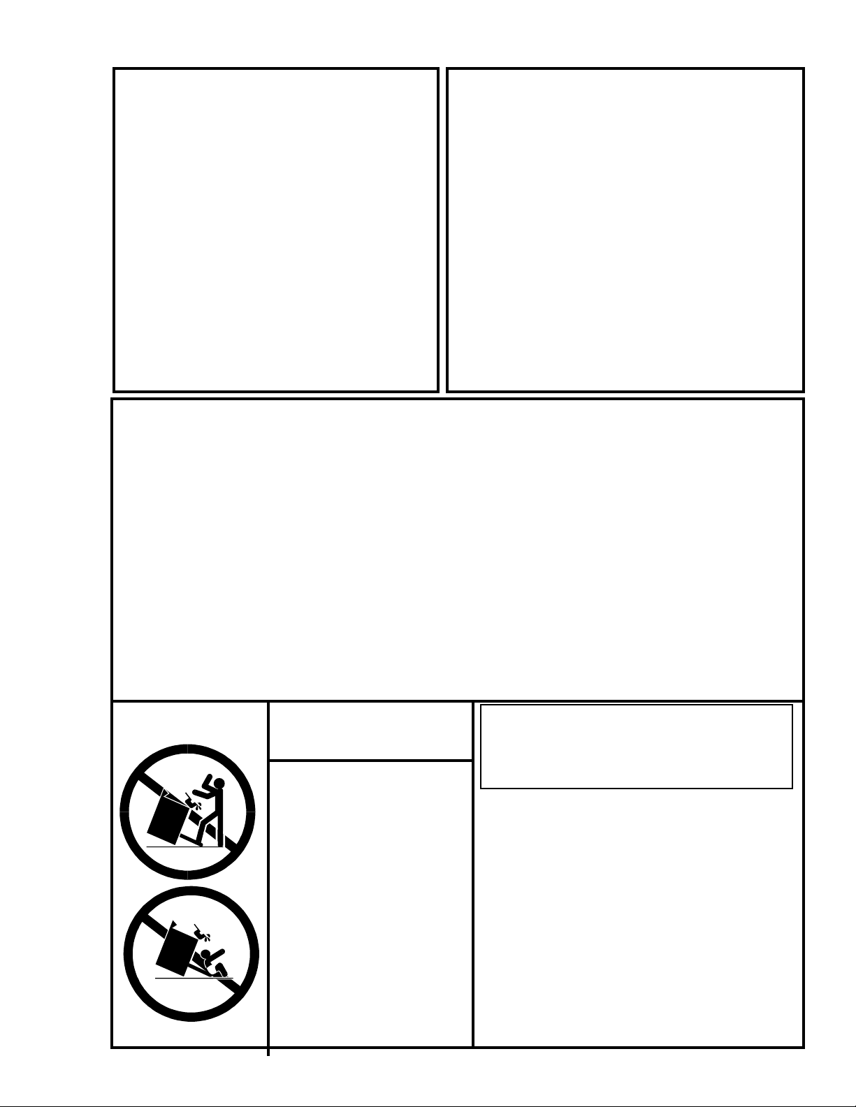
WARNING
• ALL RANGES CAN
TIP
• INJURY TO PERSONS
COULD RESULT
• SEE INSTALLATION
INSTRUCTIONS
WARNING: If the information in this manual is
not followed exactly, a fire or explosion may
result causing property damage, personal injury
or death.
Do not store or use gasoline or other flammable
vapours and liquids in the vicinity of this or any other
appliance.
WHAT TO DO IF YOU SMELL GAS
• Do not try to light any appliance.
• Do not touch any electrical switch; do not use
any phone in your building.
• Immediately call your gas supplier from a
neighbour’s phone. Follow the gas supplier’s
instructions.
• If you cannot reach your gas supplier, call the
fire department.
Installation and service must be performed by a
qualified installer, service agency or the gas supplier.
Page 4

Page 5

T ABLE OF CONTENTS
1. Assembly and Installation.................................. 2
2. Assembly of Range Base...................................... 2
3. Assembly of Range Body to Base......................... 3
4. Assembly of Exhaust Hood to Range .......................4
5. Positioning the Range ........................................... 4
6. Installation Clearances .......................................... 5
7. Electrical and Gas Installation............................... 6
8. Exhaust Hood...................................................... 7
9. Ventless Installation.............................................. 7
10. Vented Installation ................................................ 7
11. Installation of Ducting .............................................8
12. Venting Safety Guidelines .................................... 9
13.Gas Line Installation ................................................9
14. Important Safety Instructions ...........................10
29. Care and Cleaning............................................18
30. Porcelain .............................................................18
31. Oven Cleaning .....................................................19
32. Surface Burners...................................................1 9
33. Nickel Trim ..........................................................20
34. Exhaust Hood......................................................20
35. Oven and Cabinet Light .......................................20
36. Interior Oven Rack Removal.................................21
37. Rack Supports Removal ..................................... 21
38. Oven Door Removal .............................................22
39. Broiling................................................................23
40. Broiling Pan.........................................................23
41. Oven Light............................................................23
42. Broiler Drawer Removal .......................................24
15. Exhaust Hood Safety...........................................1 0
16. Features .............................................................11
17. Sealed Burner Features.......................................1 1
18. Oven Features .....................................................12
19. Other Features ................................................... 12
20. Control Panel Layout .......................................... 13
21. Operation...........................................................14
22. Top Burner Operation...........................................14
23 Oven Lighting......................................................15
24.Range Thermostat.................................................15
25 Power Failure Operation .......................................16
26. Manually Lighting the Top Burners.......................16
27. Manually Lighting the Oven Burner.........................16
28. Clock/Timer..........................................................17
43. Setup and Trouble Shooting ...........................25
44. Burner Setup and Adjustment .............................25
45. Range Problem Solver .........................................25
46. Air Shutter Adjustment ........................................26
47. Oven Burner Assembly.......................................26
48. Trouble Shooting Guide .......................................27
49. Conversion Kits and Information...................28
50. Products ............................................................29
51. Products .............................................................31
52. Parts Diagram ...................................................32
53. Parts List............................................................33
54.RatingPlate.........................................................34
55. Wiring Diagrams ...............................................35
1
Page 6
Assembly and Installation
To fully enjoy your new range, it is important that you read this booklet thoroughly.
Note:
Please check for any damage that may have occurred during shipping. In the unlikely event that you find any shipping
damage, inform your dealer immediately!
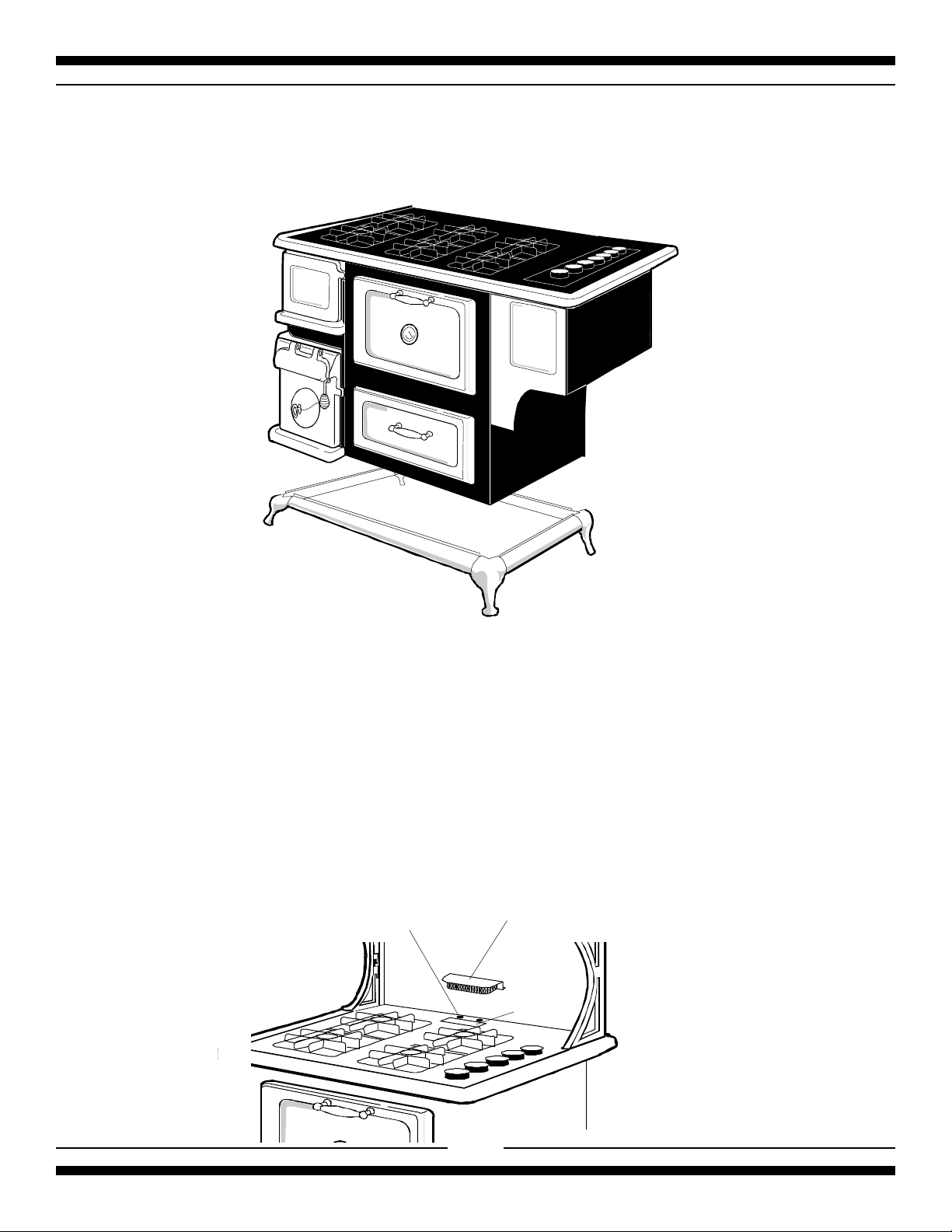
The Model 7100 and 9100 Range consists of three main parts:
The Range Base
The Range Body, and
The Exhaust Hood or Cresting Assembly
Tools required for assembly:
Slot screw driver
7/16” (11 mm) wrench or crescent wrench
5/16" (8 mm) wrench or crescent wrench
Teflon
Glider
T eflon Glider
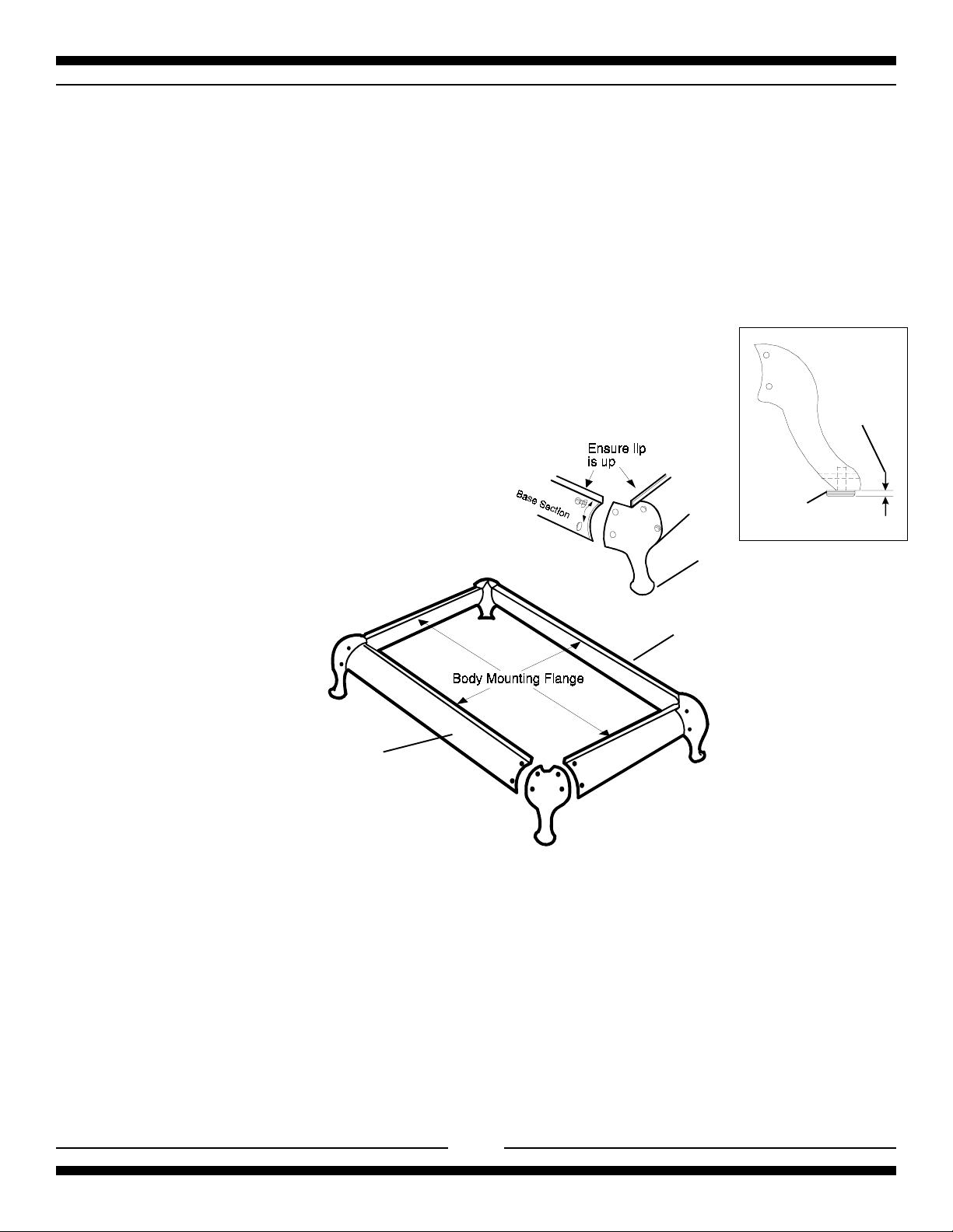
Figure 1a
(You must have a qualified gas technician install this appliance to be sure
the installation codes and rules are observed.)
1/8"- 1/4"
Painted section
Nickel plated section
Figure 1
Assembly of Range Base
1. Unpackage the base sections, legs and hardware package which are located in a carton fastened to the skid
at rear of the range (it would be a good idea to check for any damage that may have occurred during shipping).
2. Screw the base levelling bolts (with teflon glider attached) into each of the four legs. The levelling bolts are
located in the hardware package. When installing the levelling bolts, the teflon glider should
the bottom of the leg by approximately 1/8"-1/4". Adjusting levelling bolts in too far will cause the leg to drag
on the floor potentially causing damage to flooring. (see figure 1a ) . Check that gliders and floor are free of
any debris, this will ensure you do not scratch your floor.
3. Assemble base to legs using the nuts and bolts provided. For the 48" the shorter base sections are the sides
and the longer sections are front and rear. (the black painted section goes to the rear, see fig. 1). For the 30"
the base sections are all the same length, the black painted section goes to the rear, see fig. 1.
4. Hand tighten the nuts and bolts until the range base is completely assembled. Ensure that all base sections
are installed with the lip up.
5. Adjust base sections to the most upper position and tighten up the nuts and bolts.
extend
beyond
2
Page 7
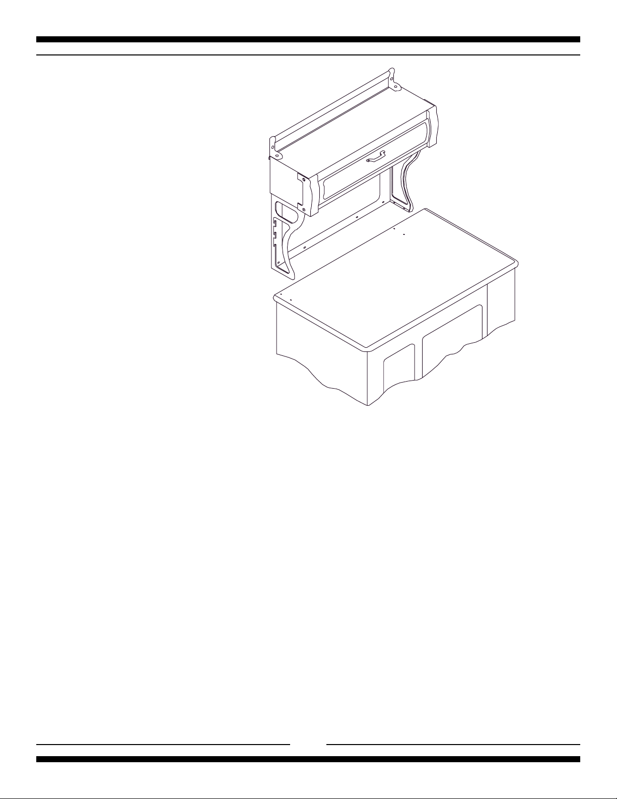
Assembly of Range Body to Base
Lift the range at the front and rear,
do not lift by nickel trim.
1. The range body rests directly on the base - no bolts are required. Two people are needed to lift it on
to the base.
2. In order not to damage the nickel trim or enamel finish, lift the range from the front and the rear . The
person at the front can first remove the oven door and use the oven opening for a hand hold. The rear
of the oven body at the bottom can be used to lift from the back.
3. Lift the range off pallet and onto base, making sure the range is sitting square and level on base. The
stove sits over the lip of the base assembly. Helpful hint: Instead of trying to square the entire stove
over the base, put one side or back on first then slowly lower the other side into position.
4. Lastly, install the oven vent deflector on the top of the cooking surface over the oven vent. Loosen
the two screws enough to slip the oven vent under the screws , and tighten up the screws. (see
illustration below)
Loosen two screws
Oven vent deflector
Oven vent
3
Page 8
Assembly of Exhaust Hood to
Range
See the manual entitled "Cabinet Assembly
Instructions for Gas , Electric
,Combination and Wood Stoves" which
is included with the cabinet .
Positioning the Range
1. When the range is fully assembled, recheck all electrical connections especially between the
exhaust hood and the back of the range. As well, check that all nuts and bolts have been tightened.
2. Ensure teflon gliders and flooring are clean, (as described in the second paragraph under
"Assembly of Range Base".)
3. Caution: On flooring with very rough surfaces or deep, large grooves the appliance may have to be
lifted and slowly slid into position.
4. Put both hands on the trim and carefully push the range into place, make sure floor is clear of all
debris. Don't forget to plug in the main power cord and the exhaust hood power cable
before the range is in its final position. See cabinet installation instructions.
5. To level the range, simply adjust the levelling screws with teflon pads located at the bottom of each
leg (the ones you assembled in step 2 of "Assembly of Range Base"). Using a 5/16 (8 mm) openend wrench turn the adjusting screw clockwise to raise up the corner, and counter-clockwise to lower
the corner. (Don't forget the teflon glider should
extend
beyond the bottom of the leg by approximately
1/8"-1/4")
6. Note: On soft kitchen flooring, the weight of the stove may cause slight depressions in the flooring.
When the range is in position and levelled, you may want to place coasters under the teflon gliders
of each leg, to protect the floor. Remove the coasters when moving the range for cleaning or
servicing.
4
Page 9
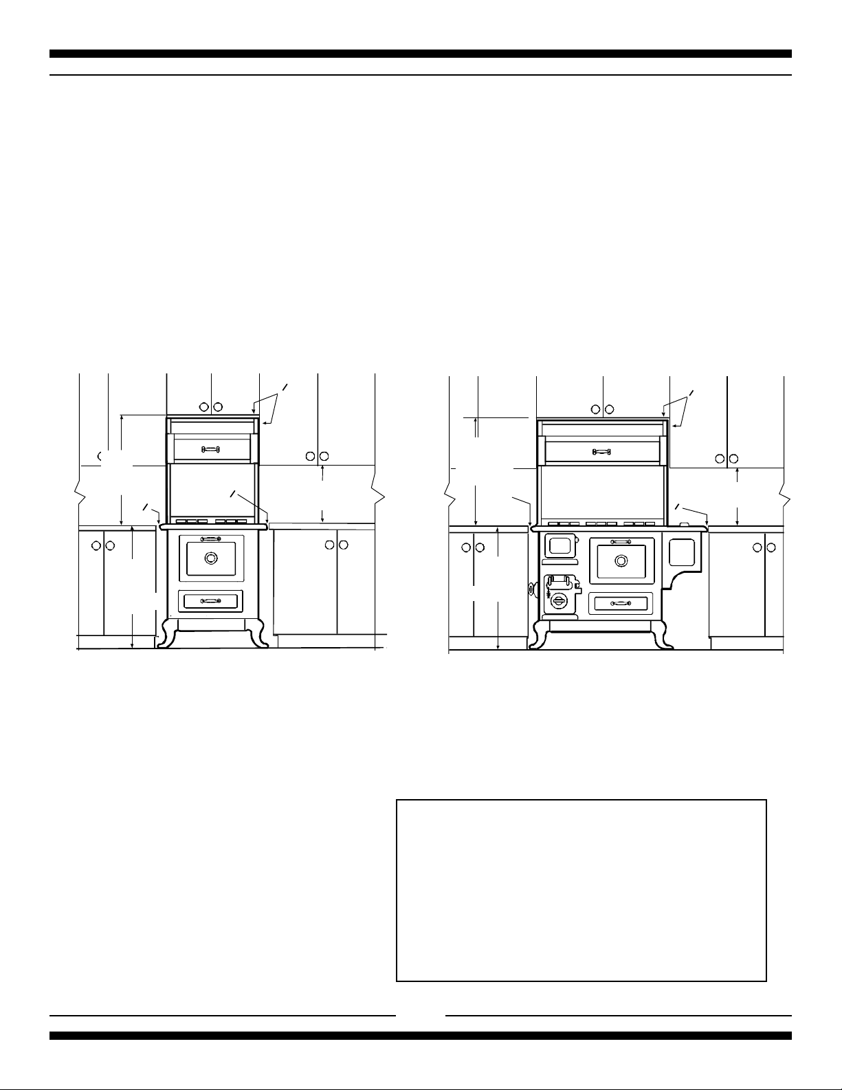
Installation Clearances
If the range must stand beside a refrigerator, it is important for proper air circulation, that there be at least
5" of space between the two appliances.
Do not install range closer than 1/2" from adjacent surfaces.
To eliminate the risk of burns or fire by reaching over heated surface units, installation of cabinet storage
space above the surface units should be avoided. If there is existing cabinet storage space have at least
30" of clearance. (see fig 3)
For best cooking results, your range should be level. This can be checked with a carpenter’s level
on top of the cooking surface and across the oven rack. If levelling is required, adjust the leveller screws
under one or more of the legs (see "Positioning the Range" step 4).
min
30 1/4"
768 m m
0
0
max
36 "
914 mm
Model 9100 Installation Clearance
0
768 mm
min 18"
457 mm
Fig 3 Installation Clearances
Installation Clearances
min
30 1/4"
1"
25 mm
min
36 "
914 mm
0
0
Model 7100 Installation Clearance
min 18"
457 mm
The clearances in the table are also stated on the
rating plate and on a reproduction of the plate on the
back page of this manual. (see "installation
clearances" diagram Fig. 3)
Surface adjacent to cook top-left (7100).............. 1” (25mm)
Surface adjacent to cook top-right (7100) ............ 0” (0 mm)
Surface adjacent to cook top (9100) .................... 0” (0 mm)
Surface adjacent to warming oven........................ 0” (0 mm)
Cook top to underside of adjacent cabinets ... 18” (457 mm)
Cook top to underside of cabinets.............30 1/4” (768 mm)
Maximum depth of overhead cabinets ............ 13” (330 mm)
Maximum depth of counters .......................... 24” (610 mm)
Maximum height of counters.......................... 36” (914 mm)
Rear clearance..................................................... 0” (0 mm)
5
Page 10
Electrical Installation
THE MODEL 7100/9100 GAS RANGE MUST BE ELECTRICALLY GROUNDED IN COMPLIANCE WITH LOCAL
CODES AND IN THE ABSENCE OF LOCAL CODES, WITH THE NATIONAL ELECTRICAL CODE ANSI/NFPA
70 “LATEST EDITION” IN THE U.S. OR THE CANADIAN ELECTRICAL CODE, PART I, CSA STANDARD C22.1
IN CANADA or YOUR NATIONAL ELECTRICAL CODE
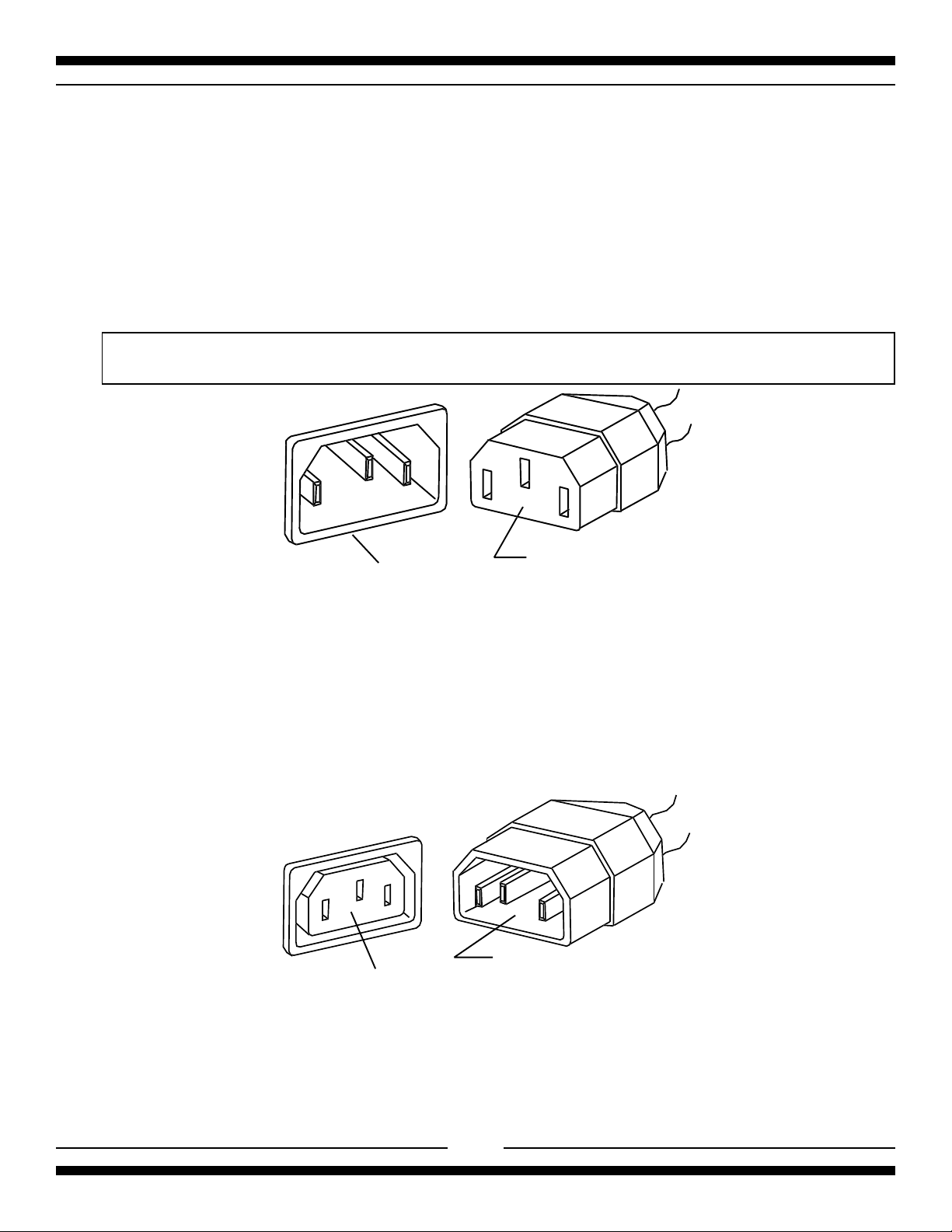
Connect the female end of the power cord to the main power (male) receptacle at the rear of the stove. See page 8 for
receptacle locations and figure 4 for receptacle illustration
This range must be plugged into a properly grounded/earth, receptacle. The grounding/earth prong must not be removed,
from the plug. DISCONNECT THE ELECTRICAL SUPPLY BEFORE SERVICING THE APPLIANCE.
The receptacle to be used for this appliance must be wired to STANDARD WIRING PRACTICES.
male receptacle
Main power hook-up
Figure 4
female end of
the power cord
Exhaust Hood Electrical Connection
After your exhaust hood has been installed the very last thing to do is to connect the special plug to the range. The
female receptacle for the exhaust hood is located at the rear of the stove by the main power (male) receptacle (See
page 8 for receptacle locations and figure 5 for receptacle illustration). Simply plug the cabinet power cord into the
receptacle, be sure to test all functions of the cabinet.
male end of the
cabinet power cordfemale receptacle
Cabinet power hook-up
Figure 5
6
Page 11
Exhaust Hood
Your range is equipped with a two speed range hood that may be either vented directly to the outside, or may be
installed ventless. A set of exhaust filters are included with your hood. The filters should be cleaned periodically in
soapy water. Extras are available from your dealer or directly from Heartland Appliances Inc. Please order 4 or more
filters at one time to save freight and handling charges. Phone your dealer for pricing and ordering instructions.
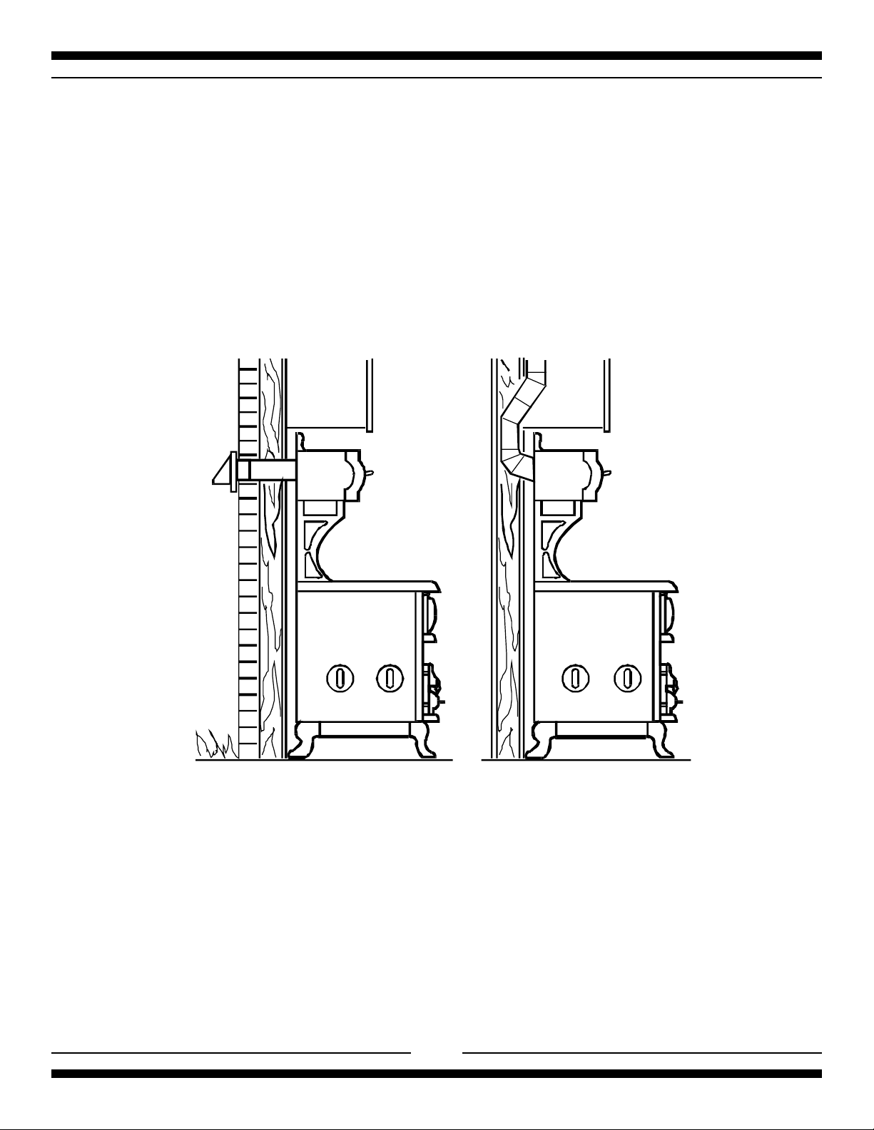
Ventless Installation
Your unit is already set up for ventless operation. Cooking fumes are drawn through the filters and exhausted thru
the rear of the hood, back into the room. Install the exhaust filters in their location under the cabinet by first removing
the light lens. Then on one side, insert one of the filters into the grooves (front and rear of the cabinet) and slide
into place. Repeat these steps for the second filter
Figure 6
Exhaust venting
options
Vented Installation, Tools, Material, and Dimensions
Tools required to install vented hood:
Hammer Slot screwdriver
Pliers Electric drill
Measuring tape Drill bits
Sabre saw OR Keyhole saw
Materials Required:
Duct—enough to go through wall or attic to outside. Elbows as required.
Roof cap or wall venthood
Caulking to seal around duct
Sheet metal screws
The above are standard parts and are available at any hardware store or heating contractor.
7
.
Page 12
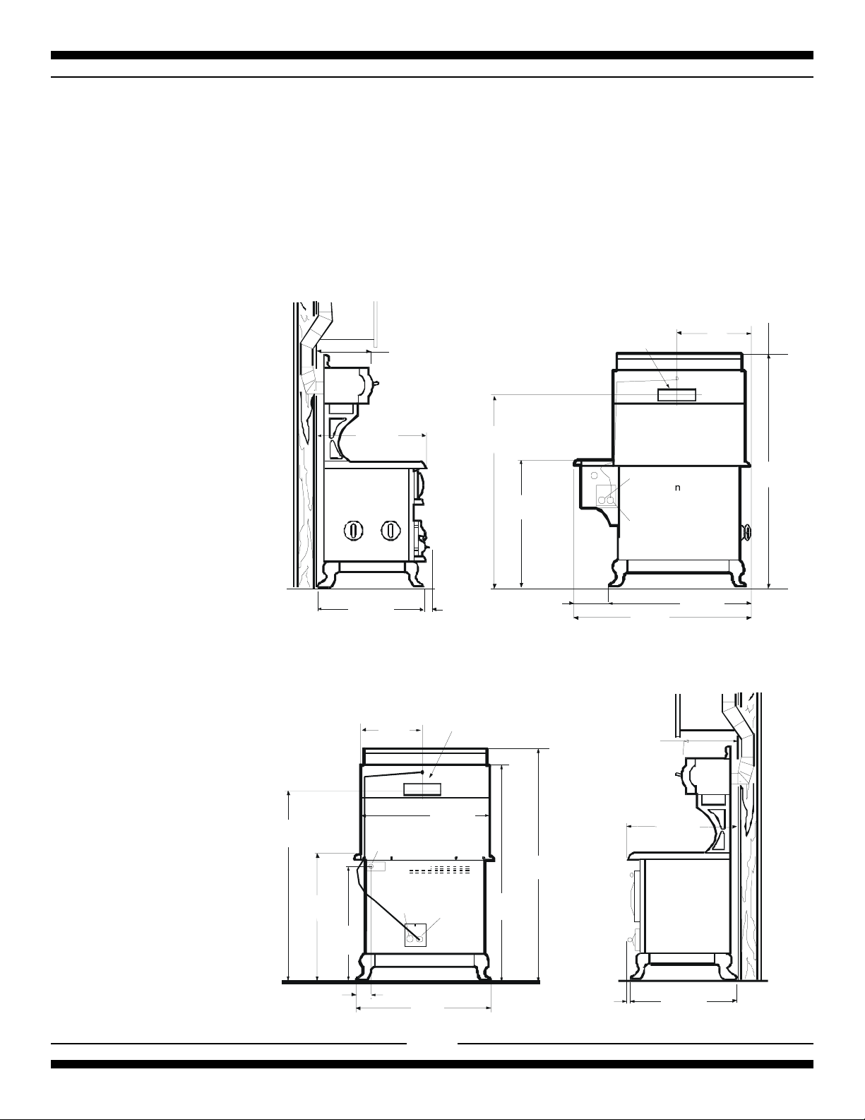
Installation of Ducting
Installation through an outside wall
Remove air deflector (used for ventless operation only). Cut appropriate-sized hole through the wall directly behind
the range hood outlet (see Figure 6 ,page 7), making sure no wall studs are cut. Push range into position. From
outside of the house, measure distance from the siding to the range outlet. Cut duct pipe that length, plus 1" (25mm)
for overlap into outlet. Attach vent hood to pipe. Caulk the back of vent hood and around pipe where it goes through
wall and into range hood outlet so caulking seals against outside siding.
Complete installation by following directions under Ventless Installation.
Installation through an attic
to an outside wall
If the vent elbows are
embedded in the wall, the
range may be positioned as
shown in Figure 6. Continue
the duct through the ceiling
into the attic. Terminate duct
either on an outside wall just
below the sofit using a vent
hood or through the roof with
a roof cap. Seal with caulking
around and under cap or hood.
Complete your installation by
following directions under
Ventless Installation.
787
29
756
31.0"
mm
3/4 "
mm
14 7/8 "
378mm
14"
356 mm
56 "
1416 mm
1/8"
36
917
mm
1 1/4 "
mm
32
235
9 ¼"
Model 7100
Range H ood
O utlet : 3 1 /4"x 10"
83 mm x 254 mm
Range Hood Outlet:
3
1/4" x 10"
83 mm x 254mm
Power In
(
direct con ect)
8 ft (2.4m) cord supplied
Exhaust Hood In
(female recepticle)
47 1/2"
1207 mm
mm
14. 0"
356 mm
19"
483
38 1/4"
72 m m9
mm
66
1682
1/ 4"
mm
56 "
142 2 mm
36 1/8"
917 m m
864 m m
33/4"/92mm
34 "
29 3/4"
756 mm
Gas Inlet-1/2 NPT
Power In
direct
(
connection)
8 ft (2 .4 m ) c o rd
supplied
29 3 /4"
756 mm
Exhaust
HoodIn
8
66 1 /4 "
1682 m m
62 3/8"
1585 m m
Model 9100
2"
51 mm
31.0"
787 m m
29 3 /4 "
756 m m
Page 13

Venting Safety Guidelines
Installation must be done in accordance with all local and national codes. Use only materials which conform to local codes
in effect. Be sure power is disconnected before doing any electrical work. All duct work must be metal. Do not use plastic
duct. The range hood should never be exhausted into a wall cavity or an attic where an accumulation of grease
could become a fire hazard.
When the installation is completed, turn on the fan and make sure that there are no obstructions in the line.
Gas Line Installation
The Model 7100 / 9100 can be operated on either natural gas or liquid propane (LP) and are set for natural gas OR
propane (LP) gas at the factory. Be sure your range is correctly installed by a qualified serviceman or installer for the
type of gas on which it is to be used.
When preparing to install the 9100, be aware that there are several alternative locations for the gas supply pipe to enter
into the stove. For reasons of appearance you may want to conceal the gas supply pipe, and this can be achieved by
routing the supply pipe through knockouts located on the rear or at the bottom of the stove (see illustration below). To
use the alternative locations, the back panel must be disassembled and the selected knockout removed. Route the pipe
through the knockout and up to the manifold. Reassemble the back panel to the stove. Model 7100 has only one supply
pipe installation location. (see illustration below)
THE RANGE MUST BE INSTALLED IN COMPLIANCE WITH LOCAL CODES, AND IN THE ABSENCE OF LOCAL
REQUIREMENTS, THE INSTALLATION MUST CONFORM WITH THE NATIONAL GAS CODE.
Note
: Appliances installed in the state of Massachusetts:
- This appliance can only be installed in the state of Massachusetts by a Massachusetts licensed plumber or
gasfitter
- This appliance must be installed with a three (3) foot / 36 inch long flexible gas connector
- A “T” handle type manual gas valve must be installed in the gas supply line to this appliance
THE APPLIANCE MUST BE ISOLATED FROM THE GAS SUPPLY PIPING SYSTEM BY CLOSING ITS INDIVIDUAL
MANUAL SHUTOFF VALVE DURING ANY PRESSURE TESTING OF THE GAS SUPPLY PIPING SYSTEM AT TEST
PRESSURES EQUAL TO OR LESS THAN 3.5 KPS (1/2 PSIG).
The maximum propane/natural gas supply inlet must not exceed 14 inches of water column. The minimum gas supply
inlet should be at least 5 inches of water column for natural gas or at least 11 inches of water column for LP gas.
5 1/4"
133 mm
G as Inlet on manifold
All electrical
components
behind panel.
Knock-o uts for
gas piping in
bottom panel.
34
864 mm
9 1/2
240 mm
3 3/4
95 mm
4 1/2
115mm
9100 optional gas inlet locations
Knock-outs for gas
piping behind back
panel.
13 3/4
350mm
5 7/8
149 mm
30"
762 mm
10"
254 mm
Gas Inlet to manifold
7100 optional gas inlet location
9
Page 14

Important Safety Instructions
1. PROPER INSTALLATION—BE SURE YOUR APPLIANCE IS PROPERLY INSTALLED AND GROUNDED BY
A QUALIFIED TECHNICIAN.
2. NEVER use this appliance as a space heater to heat or warm the room. Doing so may result in Carbon
Monoxide poisoning and in overheating of the oven.
3. Do not leave children alone. Children should not be left alone or unattended in area where appliance is in use.
They should never be allowed to sit or stand on any part of the appliance.
4. Wear proper apparel—loose-fitting or hanging garments should never be worn while using the appliance.
5. User servicing—do not repair or replace any part of the appliance unless specifically recommended in the
manual. All other servicing should be referred to a qualified technician.
6. Storage in or on appliance—flammable materials should not be stored in an oven, near surface units or in range
cabinet.
7. Do not use water on grease fires—smother fire or flame or use dry chemical or foam-type extinguisher.
8. Use only dry potholders—moist or damp potholders on hot surfaces may result in burns from steam. Do not
let potholder touch hot heating elements. Do not use a towel or other bulky cloth.
9. NEVER cover any slots, holes and passages in the oven bottom or cover an entire rack with materials such as
aluminum foil. Doing so blocks air flow through the oven and may cause Carbon Monoxide poisoning. Aluminum
foil linings may also trap heat, causing a fire hazard.
10. It is a good practice to install CO detectors when any gas appliance or furnace is present in the home. Please
follow manufacturer’s recommendations for location and installation of CO detectors.
Exhaust Hood Safety
Caution: Do not store items of interest to children in cabinet above the range or on top of range cabinet.
Children climbing on range to reach items could be seriously injured.
1. Clean exhaust hood frequently—grease should not be allowed to accumulate on hood or filter.
2. When flaming foods under the hood, turn the fan off. The fan if operating may spread the flame.
Oven Safety
Do not touch heating elements or interior surfaces of oven—heating elements may be hot even though they
are dark in colour. Interior surfaces of an oven become hot enough to cause burns. During and after use, do not touch,
or let clothing or other flammable materials to contact heating elements or interior surfaces of oven until they have
had sufficient time to cool. Other surfaces of the appliance may become hot enough to cause burns—among these
surfaces are, for example, oven vent openings and surfaces near these openings, oven doors.
1. Use care when opening door—let hot air or steam escape before removing or replacing food.
2. Do not heat unopened food containers—buildup of pressure may cause container to burst and result in injury.
3. Keep oven vent ducts unobstructed.
4. Placement of oven racks—always place oven racks in desired location while oven is cool. If rack must be moved
while oven is hot, do not let potholder contact hot heating element in oven.
10
Page 15

A
Features
J
F
I
Figure 7
B
D
C
E
H
Cooking Controls
The cooking controls are located on the right hand side of the cooktop; these controls offer an infinite number of heat
settings for ease and accuracy in cooking and baking.
Sealed Burner Features (see fig. 7)
A) Centre Burners - are two maximum 8,000 BTU (2.34 kW)(L/P 7,000 BTU) with simmer of 600 BTU (.2 kW)
sealed gas burners,easy clean, for medium duty cooking tasks.
B) Left Burners - front sealed burner is maximum 10,000 BTU (2.93 kW) (L/P 9,000 BTU) with simmer of 1000
BTU (.3 kW) and rear is maximum 8,000 BTU (2.34 kW)(L/P 7,000 BTU) with simmer of 600 BTU (.2 kW)
accurately maintain temperature.
C) Right Burners (48" models only) - front sealed burner is maximum 10,000 BTU (2.93 kW) (L/P 9,000 BTU)
with simmer of 1000 BTU (.3 kW)and rear is maximum 8,000 BTU (2.34 kW)(L/P 7,000 BTU) with simmer of
600 BTU (.2 kW) , one for large jobs, one for small, easy clean.
D) Gas Burner Controls - allow an infinite selection of cooking temperatures, 4 controls on model 9100 and 6 controls
on model 7100. All models feature "auto-reignition", which means if for any reason the flame goes out, it
automatically begins to spark to re-ignite the burner!
11
Page 16

G
K
Fig. 8
L
Oven Features
E) Oven Temperature Control - With infinite bake temperature and broil control. All units feature "auto gas shutoff",
which means that if for any reason the flame goes out, gas to the oven burner shuts off!
F) Gas Oven Features: -baking
-3 position racking
-2 cubic feet of energy efficient area (.05 cubic meters)
-13,500 BTU (3.96Kw) oven burner
Other Features (see fig. 8)
G) Digital Clock - With minute minder.
H) Broiler - Broiler drawer located under the oven, glides open for easy access, for all your broiling needs.
I) More Storage - (model 7100 only) lift and open the cast door to gain access to more storage area.
J) Cabinet Door - the minute minder, exhaust fan control and overhead light switch are concealed behind the cabinet
door.
K) Three position switch - Controls high and low for exhaust fan centre position is “OFF”.
L) On -off switch - controls overhead light in exhaust hood.
12
Page 17

Control Panel Layout
Model 7100
Control Panel
0
6
5
4
6
5
4
6
5
4
6
5
4
6
5
4
6
5
4
1
2
3
0
1
2
3
0
1
2
3
0
1
2
3
0
1
2
3
0
1
2
3
Left Rear Burner
Control(Medium)
Left Front Burner
Control (Large)
Centre Rear Burner
Control (Medium)
Centre Front Burner
Control (Medium)
Right Rear Burner
Control(Medium)
Right Front Burner
Control(Large))
Oven Control
The control panel is laid out in a straight line
and each control is identified by a graphic on
the right side of the knob.
Model 9100
Control Panel
0
6
5
4
6
5
4
6
5
4
6
5
4
F
C
200
95
250
120
300
145
5
0
3
1
7
0
0
4
0
5
0
2
1
2
3
0
1
2
3
0
1
2
3
0
1
2
3
0
5
2
6
5
0
4
5
5
3
2
Left Rear Burner
Control(Medium)
Right Rear Burner
Control(Medium)
Left Front Burner
Control (Large)
Right Front Burner
Control(Medium)
Oven Control
The operation of the controls
are described in the following
pages.
13
Page 18

OPERATION
Top Burner Operation
Lighting the Top Burners
Your range is equipped with a spark ignition system that is electrically operated. You need only to push
in and turn the knob to any position and the burner will light. When you turn the knob, you will hear a
distinct clicking noise. After the burner lights, the clicking noise will stop. Note: when lighting any one
burner, all burners will spark, but only the burner that you have selected will light. All models feature
"auto-reignition", which means if for any reason the flame goes out, it automatically begins to spark
to re-ignite the burner!
See page 16 for manual lighting procedure.
0
6 (HI) - Quick start for cooking, brings water to
boil.
5 (MED HI) - Fast fry, pan broil, maintain fast boil
on large amount of food.
6
4 (MED) - Saute and brown; maintain slow boil on
large amount of food.
5
3 (MED LOW) - Cook after starting at MAX; cook
with little water in covered pan.
2-1 (LOW) - Steam rice, cereal; maintain serving
temperature of most foods.
For safety reasons, always adjust the burner controls so that flames do not extend beyond
the edges of pots, pans or other cooking utensils.
Large pots or other over-sized cooking utensils may cause random sparking from the
burner. To avoid this condition lower the flame size or use smaller-sized cooking utensils.
Do not use a griddle directly on top of grates. To avoid random sparking, please use the
Heartland Griddle Pan Kit for Classic Ranges part #7602 (complete with griddle pan
support) may be purchased from your dealer or directly from Heartland.
4
Top Burner Control
3
1
2
14
Page 19

Oven Cooking
Oven Lighting
Open oven door. There are 2 holes in the oven bottom so you can view the oven flame. Push
in and hold down the oven knob and select the desired oven temperature. You should hear
sparking until the oven flame ignites. You must continue to keep oven knob depressed
for 5-6 seconds after the oven ignition has occurred. The extra 5-6 seconds is to heat up
the safety thermocouple to allow proper oven control. (releasing the knob too early will
extinguish the flame) All units feature flame sensing auto shutoff, so if for any reason the
flame goes out, the gas supply to
the oven is shut off automatically!
Please note: the first time the oven
is used, the oven lighting procedure
may have to be repeated 2-4 times
to push out any air in the gas lines.
If the oven flame
does not light
in
10 seconds, STOP. Release oven
knob, this will prevent any further
gas from going into the oven. Wait
at least 1 minute before trying to
light oven again. If you are still not
successful see "trouble shooting
guide".
250
120
300
145
200
95
F
C
0
Range Thermostat
The temperature in the oven is
transmitted to the thermostat by
5
1
7
0
0
0
4
5
0
2
0
5
4
5
3
2
5
0
0
6
2
5
3
0
the sensor tube located at the rear
of the oven. It must always be in
Oven Control Knob
position on its mounting clips and
should not be bent. The sensor
causes the burner to maintain the
desired oven temperature.
Broil
When broiling, the oven control knob should be set at 550°F (290°C). The oven door should
be positioned at the first stop position on the door hinge, which will leave the door open approx.
5 inches. If the door is closed during broiling, the temperature in the oven could reach 550°F,
causing the oven burner to cycle down to the "low position", which will effect your broiling time.
15
Page 20

Power Failure Operation
If electrical power is interrupted in your area, you can still cook meals on your Heartland gas range .By following these simple
directions you will be able to use the burners and oven without the benefit of electricity.
Caution: make sure your hands and clothing are clear of the burner you are lighting!
Top Burner Control
Manually Lighting the Top Burners
1) Remove cast grate, for unobstructed access to the burner head.
2) Hold a flame source to the desired burner head.
We recommend a barbecue lighter to use as a flame source.
3) Push in and turn the corresponding control knob to the medium setting.
4) Carefully replace cast grate, keep fingers clear of the flame.
5) After the burner lights, adjust flame size as required.
Please note that the "auto reignition" feature will not function without electricity, therefore pay close attention to
any burners in use while electrical power is interrupted!
When lighting top burners manually, set control to the
medium setting to prevent potential injury from the
flame when replacing the grate.
Manually Lighting the Oven Burner
The oven can be operated safely by lighting the oven burner in the following
manner:
1. Remove the oven bottom.
2. Hold a flame source at the front of the burner directly beside the igniter. We
recommend a barbecue lighter as flame source.
3. Push in and hold down the knob, continue to hold down the oven knob and
select the desired oven temperature.
4. You must hold oven knob down for at least 10 seconds after ignition, to
activate the oven safety thermocouple. (releasing the knob too early will
extinguish the flame).
When lighting oven burner manually, light the burner
at the igniter. Keep hands and clothing away from
open flame!
5. If the oven flame
this will prevent any further gas from going into the oven. Wait at least 1
minute before trying to light oven again. If you are still not successful see
"trouble shooting guide".
6. Place oven bottom back onto position, Caution keep fingers and clothing
does not light
in 10 seconds, STOP. Release oven knob,
away from the flame!
Please note that the flame sensing auto shutoff feature
if for any reason the flame goes out, the gas supply to the oven is shut off automatically!
is still functional
without the benefit of electricity so
16
Oven Burner and
Igniter
Page 21

Minute minder
Bell symbol indicates minute
minder in operation
Clock / Timer
NOTE: Clock must be set or your timer will not function!
Adjust setting up
Adjust setting down
Functions:
Power on
Display is flashing
Set time of day
Press left button" ". Set time of day with " " and
" " buttons. This function remains activated for 7
seconds after the last " " / " " operation!
Set minute minder
This function is permanently activated and can be immediately
set with " " and " " buttons.
During setting, the units are 10 seconds.
During count down the minute minder has priority in the
display. The units are seconds.
The maximum time is 99 minutes.
Reset minute minder
Press " " and " " button together and release
" " button first.
Signal
The signal after time out will stay on 7 minutes if
it is not been reset with the " " button (Only one
touch.)
Signal Sound
The sound of the signal can be changed if desired.
When the display show time-of-day, the signal
frequency can be selected by pressing the " "
button.
Three different frequencies are selectable.
17
Page 22

Care and Cleaning
CAUTION: When cleaning the cooking surface around the valve cover plate, be aware that
detergents may corrode the electrical contacts on the valve switches (preventing an ignition
spark) and may also degrade the gasket seal on the valve itself (causing a gas leak). To
prevent damage to these components, remove valve cover and wipe up excess detergents
around and on these components, or, remove valve cover for cleaning, thereby eliminating
the chance of detergents coming in contact with these components. When removing valve
cover remember to unplug the power to the range.
Porcelain
Keeping it clean
The porcelain is very serviceable and simple to clean, but because it is glass, it will not
withstand rough handling or abuse. Never clean porcelain parts while stove is hot. Porcelain
is glass and sudden changes in temperature may cause cracking. Clean porcelain surfaces,
using warm soapy water, glass cleaner or non-abrasive cleaner and a soft cloth. Avoid
abrasive cleaners.
If any acid-based food or liquid, such as lemon juice or tomato juice is spilled on the range wipe
it at once to prevent staining.
Note: Red appliances only - a red wax coating has been added for preparation purposes which
may wear off during cleaning - this is normal and does not affect finished product.
To move range for service or cleaning
WARNING
RANGE BODY RESTS ON BASE
WHEN MOVING , MOVE BY BASE ONLY
1. Disconnect gas line and electrical power.
2. Place temporary floor protection in front of range.
3. Slide out from wall and place floor protection
under front legs and slowly pull out to gain access
to rear.
4. To reinstall, reverse these instructions.
Important
Keep appliance clear from combustible materials,
gasoline and other flammable vapour and liquids.
Do not obstruct the flow of combustion and ventilation
air.
18
Page 23

Oven Cleaning
Your range must be kept clean and free of accumulations of grease or spillovers which may ignite.
This is most important in the oven and broiling compartment. When cleaning the oven, make sure
the oven is turned “Off” and oven is cool. For simple spills, clean the oven with a strong solution of
detergent, then wipe with a clean damp cloth and dry.
When food or grease has burned on the oven lining, apply a strong oven cleaning compound. Follow
directions on the package, but avoid applying a strong cleaner to the front flanges or sides of end
panels because it may destroy the oven door seals or plated surfaces.
Oven racks, oven rack supports, broiler pan rack, oven bottoms, and broiler pan are all removable
for easy cleaning. Oven racks may be cleaned in your sink with dish cloth and detergent. If spillage
has remained on the racks for an extended period, more vigorous cleaning with a steel wool soap
pad may be required.
Surface Burners
Top burners require little care other than to wipe off the head of each burner. If a boilover occurs,
the burner cap can be easily lifted out so burner port holes can be cleaned in hot soapy water with
a soft brush. There are no bolts or screws to remove. The igniter must also be kept clean to ensure
quick positive starts. Simply lift the burner cap and clean. When replacing, be sure the tab is locked
securely in position on the burner base. For normal or everyday cleaning of light spills, wipe the
burner caps with a damp cloth. For heavy duty cleaning—cooked spills, oil stains, etc. scrub with
a tub and tile type of cleaner. Rinse thoroughly after every cleaning operation. Wipe away excess
water .
cap
flame spreader
burner base
19
Page 24

Nickel-Plated Trim
Nickel may be cleaned with any non- abrasive chrome and metal polish or Windex and a soft
cloth. If any acid-based food or liquid, such as lemon juice or tomato juice, is spilled on the
range, wipe it at once to prevent staining.
Exhaust Hood
Exhaust filters are included with your exhaust hood. The filters may be cleaned periodically
in soapy water. The filters should be replaced every 4 months or when they begin to restrict
air flow. Extras are available from your dealer or directly from Heartland Appliances. Please
order four or more at one time to save freight and handling charges.
See instructions for ordering on page 7 under " EXHAUST HOOD "
The inside of your exhaust hood should be inspected periodically for grease buildup (a fire
hazard) and cleaned as required with soap and water.
Oven and Cabinet Light Replacement
Before replacing lamp, disconnect the power at the main fuse or circuit breaker panel. When
replacing light bulbs, wait until the oven and bulb are cool. Remove oven light lens by simply
unscrewing it counterclockwise. The bulb can then be unscrewed easily. Always handle the
bulb with a dry (never wet) cloth to protect hands. If light bulb should break, disconnect power
to range by unplugging it or removing the fuse from the panel before touching the bulb.
Replace the bulb. Use only a 40 watt oven bulb available at your local hardware store or
appliance dealer.
When cleaning the oven, do not touch lens with a wet cloth.
WARNING!
Do not sit, lean, lift or stand on the
doors or drawers of this range as
possible injuries may result.
20
Page 25

Interior Oven Rack
The oven rack is designed with stop-locks so that when placed correctly on the supports, it (a) will stop before
coming completely out of the oven, (b) will not tip when placing or removing food.
To install, place the rack "feet" on the rack support and push the oven rack backward along the rack support.
(see 1 )
Push the oven rack all the way to the back until the oven rack slips off the end of the rack support.
(see 2 )
Then pull rack support ahead slightly to engage the "feet" with the rack support. (see 3 ) To remove reverse
assembly procedure.
Oven rack "feet"
1
Oven rack
Rack Support
2
3
Rack Supports
The oven rack supports are designed to interlock into the oven sides but are easy to remove. First remove
oven racks, then grasping the lower portion of the rack support swing it out to approx. 45 degrees and gently
pull down. Assemble in reverse order.
21
Page 26

Removal of Oven Door
At times you may want to remove the oven door for thorough cleaning of the oven. Removal of the oven door
is easy:
1) Open oven door, and latch the brass catches on to the upper leg of the hinge. (see below).
Make sure the catch is securely hinged.
2) With a hand on each side of the door lift the door slightly, and pull out.
3) The door weighs about 17 lbs (8 kg) , so exercise caution when removing the door.
4) To replace the door reverse this sequence.
WARNING!
Do not sit, lean, lift or stand on the doors
or drawers of this range as possible
injuries may result.
Make sure the brass catch is
securely hinged
Upper leg
Brass catch
Oven door
22
2) and pull out
1) lift the door slightly,
Page 27

Broiling
Broiling is cooking by direct radiated heat from above the food. It is fast because no preheat time is required
and the food is close to the burner.
When broiling, the oven control knob should be set to the broil symbol or the 550 setting on the knob. The oven
door should be positioned at the first stop position on the door hinge, which will leave the door open approx.
5 inches. If the door is closed during broiling, the temperature in the oven could reach 550 F causing the oven
burner to cycle down to the "low position", which will affect your broiling time.
Broiling guide charts in most cookbooks are approximate. Your personal experience using the broiler will
establish the most desirable cooking time.
Broiling Pan
The broiling pan grille allows for the proper drainage of cooking grease into the lower pan. Both the griddle and
pan should always be used when broiling.
Optimum Broiling Area
Broiling Pan and Griddle
Always remove the broiler pan from the compartment as soon as you finish broiling. It makes the pan much
easier to wash and there is no chance that the pan and drippings will be forgotten. Grease left in the pan can
catch fire if the oven is used without removing the grease. Let the pan cool first, then wash the pan and griddle
in hot soapy water.
Oven Light
The oven light switch is located below the nickel band on the right front side on the model 7100 and on the model
9100 right side.
switch location on
7100
23
switch location on
9100
Page 28

Storage Drawer
To remove storage drawer:
1. Remove oven door.
2. Remove oven bottom.
3. Pull drawer out until it stops.
4. With the aid of a flashlight, locate and remove the drawer stop at the left side of the drawer by removing the
two screws. (see figure 1).
5. Pull the drawer again gently until it stops. At the same time, from underneath, pull on both release
tabs (see figure 2) to disengage the drawer from the track and pull drawer out.
6. To reinstall: line up the drawer's tracks with each other, press on the bottom of the drawer and push
all the way back (see figure 3).
7. Reattach drawer stop. Please ensure the drawer is back far enough to clear
stove's fixed stops.
Drawer Stop
Reverse View/Angle
Figure 1
Drawer
Pull out to release
drawer glide
Figure 2
Stove Tracks
Figure 3
24
Page 29

SETUP AND TROUBLESHOOTING
Timer
Exhaust Fan
Speed Control
Light Switch
Burner and Oven
Controls
Oven Light
Switch
Oven Light
Broiler Drawer
Filters
Splashback
Timer
Exhaust Fan
Speed Control
Light Switch
Burner and O ven
Controls
Oven Light
Switch
Oven Light
Broiler Drawer
Filters
Splashback
Pot Storage
Burner Setup & Adjustment
The range was carefully set up and inspected at the factory but some final adjustments may be necessary
once the unit is installed.
You should check the following:
i) First check to make sure there are no gas leaks. Propane and natural gas have a very distinct smell
which is easily detected by the human nose. If in doubt, soak each pipe joint with soapy water and look
for bubbles. Do not use an open flame for testing.
ii) Check that all the controls are operating properly by lighting each of the burners. Turn the burners
on by pushing down and turning counter clockwise. Try them at low, medium and high settings.
iii) Check the quality of the flame. The top burners should have a steady, relatively quiet flame with
a 1/2" (13mm) sharp blue cone. There should be no orange flame. The oven burner should have
a clean blue flame with inner cones of 1/4" to 1/2" (6.35mm to 13mm). See figure 8.
If everything checks out, you’re “cooking with gas”. If not, refer to the gas trouble shooting guide,
page 27.
Outer Cone
In ner C one
figure 8.
25
Page 30

Air Shutter Adjustment (oven burner only)
The quality of the flame can be changed by adjusting the air shutters. Factory setting on the air shutter is 0.40" (10.6mm).
(see figure 9)
loosen screw
Reduce the shutter opening if:
• the flame appears unsteady
• is not burning all the way around
• is noisy like a small blow torch.
.4"
Increase the shutter opening if:
• the flame has yellow tips
• there is no sharp blue cone
air shutter adjustment
Figure 9
• soot appears on the bottom of cooking pans.
The oven burner air shutter is located at the base of the burner inside the broiler compartment. It can not be adjusted in place
and the oven bottom must be removed to reach it. The burner must be removed to adjust shutter.( see page 30 for burner removal)
The air shutter is adjusted by loosening the locking screw and rotating the shutter to allow more or less air into the tube. The
centred position is usually about right. Tighten the screw, replace the assembly and check the flame pattern.
Oven Burner Assembly
The oven burner assembly is visible and accessible for servicing when the oven bottom panel is removed. The burner assembly
is made up of several components as shown below.
10.6 mm
thermocouple
burner
igniter
IMPORTANT
The thermocouple and igniter positioning is very important
to the operation of the oven. These two items must be
checked before putting the appliance into operation. (see
figure 11)
NOTE: Before putting the 7100 /9100 Gas Range into service,
be sure that all the setup procedures recommended in this
manual have been completed.
Oven burner assembly
Figure 10
3/16"
4.7mm
Top View
Side Vie w
1/8"
Critical
3.0mm
Thermocouple
1/8"
C r it ic al
3.0m m
The ov en ignit or m ust
be on the cen tre of
the pipe in t he m id dle
of the first and s econd
po rt
26
figure 11
Page 31

TROUBLESHOOTING GUIDE
FOR ALL BURNERS EQUIPPED FOR REIGNITION
WITH " FLAME RECTIFICATION "
Problem Cause Remedy
A. Spark Ignition
1. No sparks when any control
knob is turned to “light”
2. No sparks when one or
some control knob(s) is
(are) turned to “light”
3. Sparking occurs at
electrodes when all control
knobs are turned off
4. All burners that are turned
on have lighted but
electrodes are still sparking
No power to spark module - module
switch faulty
Reignition electrode controlled by
knob switch is grounded or has
a high resistance leak
Electrode to far from burner
base
Disconnected switch lead or short
in switch lead
High resistance or open connection
between spark output terminal and
H.V. wire receptacle (spark will
jump small gap but sensing current
will not)
Check electrical supply to spark module with voltmeter - replace module
Check high voltage wires carefully for loose connections or pinches in the
wires; if connections are tight, replace high voltage wire
The igniter is on a eccentric pin, so rotating the igniter in its place will bring
the igniter closer to the burner base
Check all switch lead connections for looseness and wires for damage
Push receptacles firmly onto all terminals
Check positioning of shrink sleeving on receptacle – should be flush with end
of receptacle – trim if necessary
5. One or more burners have
lighted but eletrodes are still
sparking
B. Oven Burner
1. No main burner flame
2. Oven will not maintain
proper baking temperature
Defective module
Ground/Earth lead to module
disconnected or range chassis not
properly connected to ground/earth
by ground/earth lead or through
third prong of power cord plug,
combined with reversed power
supply polarity
Pots or cooking utensils (i.e. griddle
plates) are too large and are
smothering the flame causing the reignition to spark
Defective safety thermocouple Make sure thermocouple is hand tightened +1/4 turn
Defective thermostat (unit under
oven control knob) , no main burner
flame at any setting
Oven bulb not in proper location Secure oven bulb in clips that hold it in proper location
Oven bulb coated with foreign
material (i.e. oven cleaner etc.)
Oven bottom covered with aluminium
foil
Utensils too large for oven reducing
free circulation of air
Replace module
Check ground/earth connection of range chassis and ground/earth lead
connection to module
Use smaller sized pots or reduce size of flame. Do not use
griddle plate directly over top of grates. Heartland Appliances
sells a griddle kit #7602 complete with griddle support.
Replace safety thermocouple- NOTE: There are no field adjustments for this
control
Replace thermostat above - always check gas pressure before replacing
thermostat
Use fine steel wool or scouring pad to gently clean the surface of the bulb
- NOTE: Replace carefully in locating clips
If foil blocks holes or slots in oven bottom, oven heat distribution will be
affected - remove foil
Allow at least 1 1/2" to 2" (38mm to 5.0mm) clearance for air circulation
between utensils and between utensils and oven surface
27
Page 32

Conversion Kits and Information
Normally, Model 7100 and 9100 are ordered from the factory preset for either Natural Gas or Propane.
However, they can be converted after installation by performing a conversion procedure to the gas
components with the appropriate conversion kit.
The components requiring conversion are,
1) the pressure regulator,
2) top burner controls,
3)oven burner control,
4) the top burners
5) oven burner
Kits can be ordered from your dealer or directly from Heartland.
Each kit contains all the parts required for conversion, as well as instructions and a orifice removal tool.
The kits available are:
7698 7100 ORIFICE KIT NAT DOMESTIC -SABAF
7698I 7100 ORIFICE KIT NAT DOMESTIC SABAF/ISPHORDING
7699 9100 ORIFICE KIT NAT DOMESTIC -SABAF
7699I 9100 ORIFICE KIT NAT DOMESTIC SABAF/ISPHORDING
7702 7100 ORIFICE KIT LP DOMESTIC SABAF
7702I 7100 ORIFICE KIT LP DOMESTIC SABAF/ISPHORDING
7703 9100 ORIFICE KIT LP DOMESTIC SABAF
7703I 9100 ORIFICE KIT LP DOMESTIC SABAF/ISPHORDING
When ordering your kit please include your serial number to ensure the correct conversion kit is supplied
to you.
28
Page 33

See our complete line of kitchen appliances:
3010- 30" Classic II Series Refrigerator, 18 cubic
feet capacity, bottom-mount freezer drawer, and
convienient top-mount fresh food compartment.
Ice maker is available as an option. The Classic
series also offers an optional Cowl. Energy efficiency
rating 548 kwh/year. Also available in Metro 3220
and Legacy 3060 models.
3110- 36" Classic II Series Refrigerator, 22 cubic
feet capacity, top-mount freezer, counter-depth
design. Ice maker is standard. The Classic series
also offers an optional Cowl. Energy efficiency
rating 552 kwh/year. Also available in Metro 3310
and Legacy 3160 models.
3530- Legacy Gas / Electric kitchen range - 4 sealed
gas burners, electric convection oven fits in a 30"
opening! Also available in stainless steel as model 3535
Metro. Cooktop versions for both Metro 3805 and
Legacy 3800 models are available.
3630- Legacy 36" Gas / Electric kitchen range - 6
sealed gas burners or 4 sealed burners and centre grill!
Electric convection oven comes standard. Also
available in stainless steel as model 3635 Metro.
Cooktop versions for both Metro 3825 and Legacy
3820 models are available.
9720 (Built-in)- Dual oven, one convection, one
standard radiant. Also available with a
oven feature
, as model 9730
self clean
4200- 30" Gas / Electric kitchen range - 4 sealed gas
burners, electric convection oven fits in a 30" opening!
Model 3110:
shown with the
Optional cowl
(available only
with the Classic
Series)
Also available with a
self clean oven feature
, as
model 4210
5200- 48" Gas / Electric kitchen range- 6 sealed gas
burners, electric convection oven, dual fuel! Also available
with the convenience of a
self clean oven
, as model
5210
6200- 48" Electric kitchen range- 5 solid element
burners, convection oven. Also available with the
convenience of a
self clean oven
, as model 6210
8200- 30" Electric kitchen range- 4 solid element
burners, convection oven fits in a 30" opening! Also
available with a
self clean oven feature
, as model 8210
Model 1903
7100- 48" Gas or propane kitchen range - 6 sealed
gas burners, a chef's dream come true!
9100- 30" Gas or propane kitchen range - 4 sealed
gas burners, fits in a 30" opening!
1900 (Oval)- Wood burning cookstove-old
fashioned cooking available in two models
2600 (SweetHeart)- Wood burning cookstovesame as the Oval, in a smaller version!
For more information please call your dealer, or call
Heartland Appliances:
Phone 1-800-361-1517 or Fax 1-800-327-5609
29
Page 34

7100/9100 PARTS CHART
1599
1546
159 2
16071
157 0
155 6
152 11
7374
754 5
753 0
631 3
13021
130 7
111 0
111 5
914 1
1125
11201
132 0
1311
132 5
133 0
602 9
401 2
245 5
1596
15451
1575
1610
1588
6536
1551
7162
16601
5208
8455
7528
7591
3556
8200
1325
9237
6679
6198
8202
7590
6677
6676-#7100
6675-#9100
6197
6202
8204
652 2
9147
845 2
8449
1599
1546
4575
1592
46071
4570
1556
45231
7374
9530
7545
8313
9141
1110
112 01
112 5
9106
91051
9106
910
51
1115
9533
1596
45451
1610
1588
8536
1551
7162
#7100-7580
7558
7557
7560
7559
7551
7552
#9100-7581
H-976
75 77
7376
7374
752 1
7364
7956
6455
707 3
7518
1115
4012
8455
8455
75622
7561
7570
7569
7571
7917
7123
Page 35

Model 7100 / 9100 Gas Range Parts Chart
TO ENSURE THE CORRECT COLOR MATCH WHEN ORDERING
COLORED PANELS, BOTH THE COLOR AND SERIAL NUMBER
MUST BE PROVIDED.
1110 Oven Door Handle Stanchion
1120 Outer Oven Door Panel
1125 Oven Door Thermometer (Non Functional)
1307 Fire Door Frame (7100 only)
1311 Ash Pan Door - Complete (7100 only)
1320 Wire Spring Handle (7100 only)
1325 Bell Damper Handle w/rod (7100 only)
1327 Cast Bell Damper Handle (7100 only)
1330 Bell Damper (7100 only)
1546 Heartland nameplate/Clips
1551 Right Cabinet Bracket
1556 Left Cabinet Bracket
1570 Lower Cabinet Strip (7100 only)
1575 Upper Cabinet Strip (7100 only)
1588 Right Cabinet Cast Corner
1592 Left Cabinet Cast Corner
1596 Right Cresting Corner
1599 Left Cresting Corner
1610 Cabinet Door Handle
2455 Base Rail Front (7100 only)
2456 Base Rail Rear (7100 only, not shown)
3556 Gas Regulator
4012 Base Leg
4570 Lower Cabinet Strip (9100only)
4575 Upper Cabinet Strip (9100 only)
5208 Reservoir Front (7100 only)
6029 Ash Catch (7100 only)
6197 2 Speed Blower Control Switch
6198 Range Light Switch
6202 Oven Light Bulb - 40W
6313 Curved Band - Cook Surface (7100 only)
6397 Oven Door Handle
6437 Oven Door Hinges L&R (not shown)
6455 Broiler Pan & Cover 2 Pc
6522 Exhaust Hood Deflector
6536 Closet Wrap (7100 only)
6675 Exhaust Filter (9100 only)
6676 Exhaust Filter (7100 only)
6677 Exhaust Adapter Boot to 3 1/4 x 10
6679 Exhaust Blower
7073 Broiler Drawer Rack
7123 Broiler Drawer Spring
7161 Oven Control Knob
7162 Top Burner Control Knob
7355 Oven Burner
7364 Oven Burner Igniter/Wire
7374 Flue Deflector
7518 Gas Oven Drawer Heat Shield
7521 Oven Bottom Pan
7528 Valve Cover Plate (7100 only)
7530 Stove Top (7100 only)
7545 Grate - Cast
7551 Control Valve Medium Burner
7552 Control Valve Large Burner
7555 6 burner reignition harness c/w switches
7556 4 burner reignition harness c/w switches
7557 Medium Burner Cap
7558 Large Burner Cap
7559 Medium Flame Spreader
7560 Large Flame Spreader
7561 Medium Burner Base
7562 Large Burner Base
7569 Ignition Electrode (1200MM Lead)
7570 Ignition Electrode (900MM Lead)
7571 Ignition Electrode (600MM Lead)
7577/7376 Oven Burner Control (serial number required)
7580 7100 Manifold Weldment
7581 9100 Manifold Weldment
7590(7304)Spark Module (0+6)
7591(7404)Spark Module 0+2 (7100 only)
7917 Broiler Drawer Assembly
8200 Light Socket & Housing
8202 Oven Light Ass’y
8204 Oven Lens
8313 Curved Band - Cook Surface (9100 only)
8449 Oven Rack Support
8452 Oven Rack
8455 Base Rail Front / Side
8456 Base Rail Rear (9100 only, not shown)
8536 Closet Wrap (9100 only)
9106 Utility Drawer Frame
9141 Oven Door Frame Weldment
9147 Gas Oven Door Gasket
9237 Electronic Minute Minder
9530 Stove Top (9100 only)
9533 Valve Cover Plate (9100 only)
15211 Splash Back (7100 only)(serial number req’d)
15451 Cresting Panel (7100 only)(serial number req’d)
16071 Front Cabinet Door Panel (7100 only) - (serial
number req’d)
16601 Reservoir Front Insert Panel (7100 only) -(serial
number req’d)
45231 Splash Back (9100 only)(serial number req’d)
45451 Cresting Panel (9100 only) (serial number req’d)
46071 Front Cabinet Door Panel (9100 only) - (serial
number req’d)
91051 Drawer - Front Panel(serial number req’d)
13021 Fire Door Panel (7100 only) (serial number
req’d)
H-306 Ash Door Hinge - Pins (7100 only)
H-976 Spark Ignitor “O” ring
Please order by part number. Parts may be ordered from
your dealer or direct from Heartland Appliances Inc. Phone
factory for prices and ordering instruction. Phone 519-6505501 ask for the order desk.
31
Page 36

Model
7100 / 9100
1050 FOUNTAIN ST N. CAMBRIDGE,
ONTARIO CANADA N3H 4R7
Serial No. HGS
Natural Gas LP/Propane
Medium 8000 BTU/HR 7000 BTU/HR
Large 10000 BTU/HR 9000 BTU/HR
Oven 13500 BTU/HR 13500 BTU/HR
Manifold Pressure 4 IN. W.C. 10 IN. W.C.
Power Requirements 120 Volt 3 amps. 60 Hz
This appliance can be used with LP/Propane gas and Natural gas. The gas
appliance regulator must be set for the gas with which the appliance is used.
Surface adjacent to cook top-left (7100)................................ 1” (25mm)
Surface adjacent to cook top-right (7100) .............................0” (0mm)
Surface adjacent to cook top (9100) ..................................... 0” (0mm)
Surface adjacent to warming oven......................................... 0” (0mm)
Cook top to underside of adjacent cabinets .......................... 18”(457 mm)
Cook top to underside of cabinets......................................... 30 1/4” (768 mm)
Maximum depth of overhead cabinets ...................................13”(330 mm)
Maximum depth of counters ................................................. 24”(610 mm)
Maximum height of counters................................................. 36”(914 mm)
Rear clearance...................................................................... 0”
These symbols on the
nameplate mean the
product has been design
certified by American Gas
®
CERTIFIED
# 7285 S######
C
US
Association Laboratories
and Canadian Gas
Association Laboratories.
32
Page 37

Wiring Diagrams
Technical Data
- Voltage 120 v / 60 Hz
- Load 3 amps (model 9100)
- Load 3 amps (model 7100)
NOTE: Service amperage should be
calculated by a qualified electrician.
The maximum propane/natural gas supply
inlet must not exceed 14 inches of water
column. The minimum gas supply inlet
should be at least 5 inches of water column
for natural gas or at least 11 inches of
water column for LP gas.
NOTE: Gas services should be checked
by a qualified gas technician.
7100
9100
33
Page 38

 Loading...