

Page 1
Heat-Zone-240V Air Duct Kit
INST ALLATION AND
OPERATION INSTRUCTIONS
Hearth Technologies, Inc.
7571 215th Street West
Lakeville, MN 55044 USA
Approvals
The HEAT-ZONE-240V air duct kit is approved for use on
Heat & Glo Models XLR-AU, 6000, 350 and 550 series
gas heaters.
Introduction
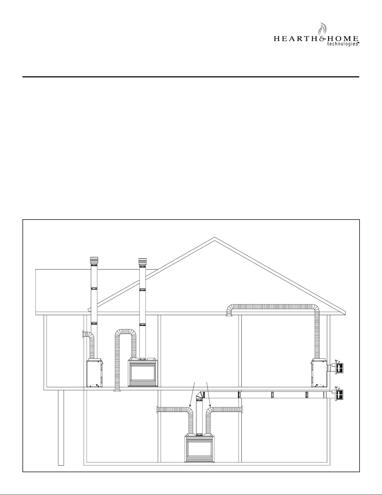
The HEAT-ZONE-240V accessory kit conveys warm air
from the heater through air duct(s) to remote locations
in the same room or other rooms of the building. See
Figures 1 and 2. One or two HEAT-ZONE-240V kits can
be installed on the heater.
Possible Air Duct Runs/Locations
Preliminary Preparation
1. Contents of kit:
• 6 meters of 152 mm round duct
• Fan housing assembly
• Junction box
• Air register
• Register adapter frame
• Heater duct collar
• Duct adapter - (round to oval)
• Hardware
• 2166-191 IPI Plus auxiliary jumper
NOTICE! If any parts are missing or damaged, contact your
dealer before starting installation. DO NOT install a damaged kit.
Figure 1
WALL REGISTER
CEILING REGISTER
TWO DUCT KITS
FLOOR REGISTER
WALL REGISTER
Hearth & Home Technologies • Heat-Zone-240V Air Duct Kit • 299-900D • 7/10 1
WALL REGISTER
Page 2
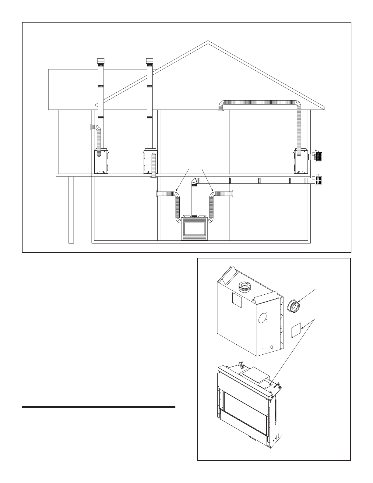
WALL REGISTER
Possible Air Duct Runs/Locations
CEILING REGISTER
TWO DUCT KITS
FLOOR REGISTER
WALL REGISTER
Figure 2
2. The Heat-Zone 240V kit is tested and safe when installed
in accordance with this installation manual. This kit is
carefully engineered and must be installed only as specifi ed. Modifying the kit or any of its components will void
the warranty, and may possibly cause a fi re hazard.
3. CAUTION: Installation of this appliance should only be
carried out by an authorized person. All relevant codes
and regulations laid down by the gas piping authorities,
municipal building regulations, electrical wiring regulations and the requirements of the AS5601 Gas Installation code must be observed.
4. Plan the location of the heater and the warm air duct
run(s).
MAXIMUM Duct Run = 6 M for useful heat output.
MINIMUM Duct Run = NA - for runs out from the heater
to adjacent room OR down to the room below.
MINIMUM Duct Run = 787 mm top of heater to room
above.
WALL REGISTER
6000 SERIES
DUCT
COLLAR
COVER
PLATE
Installation
1. Remove the cover plate from the side of the heater and
discard it.
2. Center the duct collar around the exposed hole and
attach it to the heater with 3 screws. NOTE: Do this
BEFORE fi nal positioning of the heater. See Figure 3.
Hearth & Home Technologies • Heat-Zone-240V Air Duct Kit • 299-900D • 7/102
XLR-AU
Figure 3
Page 3

3.
Determine the location for the air register/fan housing
assembly. Cut a 127 x 346 mm hole between framing
members (wall studs or fl oor joists).
4. Mount and secure the fan housing assembly to framing
members so the front surface is 6 mm below the fi n-
ished wall or fl oor surface. Use the adjustable mounting
brackets and screws provided in the kit. See Figure 4.
NOTE: The brackets can be rotated 180º and mounted
to the back side of the 2 x 4 if necessary.
FAN HOUSING
FINISHED SURFACE
Figure 6
6 mm
ADJUSTABLE
MOUNTING BRACKET
Figure 4
FRONT OF FAN HOUSING
NOTE: If the fan housing is installed in a 2 x 4 wall, the
front of the housing will protrude approximately 13 mm out
of the wall. See Figure 5.
2 x 4 WALL
FAN HOUSING
13 mm
Figure 5
5. Install the air duct run. NOTE: Fold outer poly layer of
fl exible duct back to maintain clearance to combustibles
on the fi replace. Secure liner to the collar with clamp.
ROUND AIR DUCT: Attach the 152 mm round air duct
(supplied in the kit) to the heater collar and run the duct to
the fan housing. Attach the round-to-oval adapter to the
fan housing and the air duct to the adapter. See Figure 6.
OVAL AIR DUCT: Attach the round-to-oval adapter to
the heater starting collar and a 152 mm oval duct to the
adapter. Complete the duct run and attach the oval duct
to the fan housing. NOTE: 152 mm metal oval air duct is
NOT provided with this kit but can be purchased from a
heating or air conditioning ventilation supplier.
ROUND and OV AL DUCT: A combination of 152 mm round
and 152 mm oval air duct can be used in the duct run. Oval
duct components must be purchased from a heating or air
conditioning ventilation supplier.
NOTE: Support duct at intervals of no greater than four
feet with no more than 1/2 in. sag between supports or as
required per local code. Secure the duct so that clearance
to the outer wrap of the fi replace is maintained.
6. Install a wall switch in a convenient location. This switch
will control the HEA T-ZONE-240V fan operation. When
using the AUX300CE in the IPI Plus system, the AUX1
or AUX2 can control the output and ON/OFF function in
place of a separate wall switch. Note that the RC300
remote is needed.
7. Wire 240 VAC service TO the wall switch and FROM the
wall switch to the fan junction box. Use wire connectors to
secure the 240 V AC service wires to the hot and neutral
fan wires and screw the 240 V AC ground wire to the fan
junction box. See Figure 8 for isolated control wall switch.
See Figure 9 for IPI Plus with auxiliary control.
8. Screw the fan junction box to the fan housing.
9. Screw the register adapter frame and the air register to
the fan housing. See Figure 7.
10. Complete the heater installation per instructions.
Hearth & Home Technologies • Heat-Zone-240V Air Duct Kit • 299-900D • 7/10 3
Page 4

Figure 7
ADAPTER FRAME
REGISTER
FAN HOUSING
1/2 in.
(13 mm)
Operation
1. Start the heater per instructions and allow it to warm
up.
2. Turn the wall switch "ON" to start air fl ow at the air duct
register or use RC300 remote to turn on blower.
Maintenance
1. Service and maintain the gas heater per instructions.
2. Keep the air register(s) clean and free of any blockage.
3. Reference IPI Plus instructions with remote control for
fan auxiliary control.
Figure 8
FAN
STUD
BROWN HOT
BLUE NEUTRAL
YELLOW / GREEN
Isolated ON/OFF control wall switch
SWITCH
JUNCTION BOX
BROWN
BLUE
GROUND
IPI Plus with auxiliary control
JUNCTION BOX
GROUND
FAN
FAN
Figure 9
BROWN
BLUE
CONNECTION WIRE SUPPLIED
FAN
JUNCTION BOX
JUNCTION BOX AND
BY INSTALLATION
PROFESSIONAL
Hearth & Home Technologies • Heat-Zone-240V Air Duct Kit • 299-900D • 7/104
BROWN BLACK
BLUE WHITE
GREEN/YELLOW
AUX1= 3 FAN SPEEDS
AUX2= ON/OFF CONTROL HIGH ONLY
AUX1
2166-191 JUMPER
AUX2
BROWN
BLUE
GREEN/
YELLOW
APPLIANCE
JUNCTION BOX
BROWN
BLUE
GREEN/
YELLOW
 Loading...